

CLASSIFICATION
Einstufung
SUBJECT
Thema
CUSTOMER’S CODE
EvalPAN4570
Manual
Evaluation-Board for
PAN4570 Wireless Module
EvalBoard PAN4570
PANASONIC’S CODE
No.
DS-Eval4570-2400
PAGE
Seite
DATE
Datum
06.11.2006
REV.
C
1 of 20
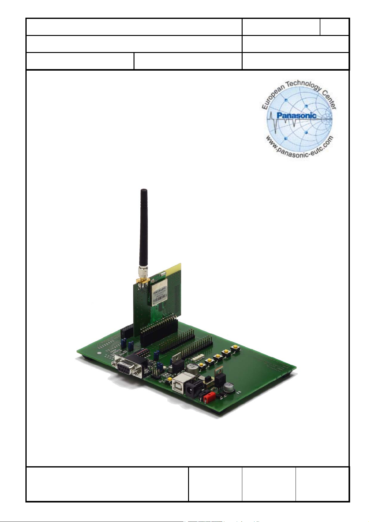
FIGURE 1 ISM RF TRANSCEIVER TESTBOARD WITH PAN4570 AND ANTENNA
European Technology Center
Panasonic Electronic Devices (EUROPE) GmbH
APPROVED
genehmigt
CHECKED
geprüft
DESIGNED
Erstellt

CLASSIFICATION
Einstufung
SUBJECT
Thema
CUSTOMER’S CODE
EvalPAN4570
EvalBoard PAN4570
PANASONIC’S CODE
No.
DS-Eval4570-2400
PAGE
Seite
DATE
Datum
TABLE OF CONTENTS
1. Overview ..............................................................................................................................3
1.1. Contents of the Evaluation Kit:................................................................................. 3
1.2. Hardware needed.....................................................................................................3
1.3. Software needed......................................................................................................3
2. Setting up the EvalBoard......................................................................................................4
3. Testboard Layout .................................................................................................................5
4. Operation of the testboard....................................................................................................6
5. Power Supply ....................................................................................................................... 6
5.1. D.C. power from a power supply.............................................................................6
5.2. D.C. power from a USB device: .............................................................................. 7
5.3. Power on.................................................................................................................7
6. Serial Port.............................................................................................................................8
7. Reset....................................................................................................................................8
8. Operation and programming ................................................................................................8
8.1. Serial communication and embedded bootloader .................................................8
8.2. Upload of EmberZNet sample applications............................................................ 9
8.3. Selecting the hardware platform ..........................................................................10
8.4. EmberTM Insight Adaptor configuration ................................................................11
9. Ember ZigBee Implementation.....................................................................................11
9.1 Flash Programming of PAN4570 ......................................................................... 11
9.2. Development of Applications...............................................................................14
9.3. EmberTM ZigBee stack ........................................................................................14
9.4. Testing for IEEE802.15.4 parameters..................................................................15
10. Schematic of the ISM RF TRANSCEIVER TESTBOARD.............................................. 16
10.1 Sheet 1................................................................................................................ 16
10.2. Sheet 2................................................................................................................ 17
10.3. PAN4570 carrierboard ........................................................................................18
11. Related Documents.......................................................................................................19
12. Document Status...........................................................................................................19
13. History for this Document..............................................................................................19
14. General Information.......................................................................................................20
15. Life Support Policy ........................................................................................................20
REV.
C
2 of 20
06.11.2006
European Technology Center
Panasonic Electronic Devices (EUROPE) GmbH
APPROVED
genehmigt
CHECKED
geprüft
DESIGNED
Erstellt

CLASSIFICATION
Einstufung
SUBJECT
Thema
CUSTOMER’S CODE
EvalPAN4570
1. OVERVIEW
The EvalKit PAN4570 allows evaluation of the wireless module PAN4570.
For a basic hardware evaluation the test software Ember Range Test Application V2.0
and the Ember
can be used for loading other applications via the serial cable to PAN4570, for example
the EmberZNet sample application “simple-lighting”.
For more information see chapter 9.3.
1.1. CONTENTS OF THE EVALUATION KIT:
- 2 x ISM RF Transceiver Testboards
- 2 x PAN4570 mounted on a carrierboard
- 2 x 2,45GHz antennas with male SMA plugs
- 2 x RS-232 cables
- 2 x battery adaptors with cable for d. c. power supply
- 1 x CD with software and documentation
1.2. HARDWARE NEEDED
EvalBoard PAN4570
PANASONIC’S CODE
TM
embedded bootloader are programmed. The embedded bootloader
No.
DS-Eval4570-2400
PAGE
Seite
DATE
Datum
06.11.2006
3 of 20
REV.
C
- 12 x Batteries (AA size) (or 2 mains supplied 9Vdc sources)
- PC with at least 1 (preferably 2) free COM Ports
1.3. SOFTWARE NEEDED
- Microsoft™ “Hyper Terminal” or any other terminal software installed on a pc
- EmberZNet installed on a pc, currently Version 2.5.0
- Ember
TM
xIDE for EM250 compiler and debugger installed on the pc where
EmberZNet is installed on
- Ember
- Ember
TM
InSight Desktop installed on a pc for network development
TM
Range Test Application V2.0 (Version Oct. 1 2006). This basic hardware
test software and the EmberZNet sample application “simple-lighting” are ready for
programming included on the CD within this kit.
Programming and debugging with Ember
TM
xIDE requires at least 1 EmberTM Insight
Adaptor.
Loading an image file (.ebl as output from xIDE) to PAN4570 via the included serial
cable is possible as well, in this case the Insight Adaptor is not needed
European Technology Center
Panasonic Electronic Devices (EUROPE) GmbH
APPROVED
genehmigt
CHECKED
geprüft
DESIGNED
Erstellt

CLASSIFICATION
Einstufung
SUBJECT
Thema
CUSTOMER’S CODE
EvalPAN4570
Important: To install and run the programs you need Administrator rights on the test PC.
Check for software updates at www.Ember.com
2. SETTING UP THE EVALBOARD
Plug a PAN4570 Carrierboard on one of the three 34-pins headers (B or C or D) as
shown in Figures 1 and 2. Please take care that pin 1 of the Carrierboard connects to
pin1 of the testboard according to the “1” marking on the PCBs.
Important: Only 1 PAN4570 carrierboard may be plugged on the testboard.
The other 34-pin headers/sockets are provided for demo application boards like sensors,
actuators, etc. On slot A a socket is mounted instead of double pin rows for applications
using a plug with pins. For details on the testboard see chapter 3 and the testboard
schematic in chapter 10.
Mount the 50Ohms 2,4GHz antenna with SMA male plug on the PAN4570 carrierboard
SMA socket.
Check if a Vcc=+2,7Vdc module supply jumper is set to the corresponding 2-pin header
(B or C or D).
Remark: Instead of a jumper an amperemeter for measuring the module current on VCC
can be connected to the module supply 2-pin header. In this case the voltage drop at the
amperemeters internal resistor reduces the Vcc voltage applied to PAN4570 depending
on the current drawn. Therefore check if the amperemeter used has an internal
resistance of sufficiently low value.
As an option a +5Vdc regulated voltage is available on the 34-pins headers (this does not
apply to usage of USB as power supply).
Important: Do not connect the +5Vdc directly to PAN4570 because it may damage the
Module.
The reason for the +5Vdc option are applications needing a higher supply voltage (i.e.
with white LEDs). In order to use +5Vdc on the headers it has to be connected by
plugging a jumper to position JP2.
The total available current from Vcc plus the current from +5Vdc is approximately 270mA
maximum, provided that the power source voltage applied to P1-P2-P3 does not drop
below approximately 6,6Vdc.
For the location of switches and jumpers on the Evaluation board see chapter 3
EvalBoard PAN4570
PANASONIC’S CODE
No.
DS-Eval4570-2400
PAGE
Seite
DATE
Datum
06.11.2006
.
REV.
C
4 of 20
.
European Technology Center
Panasonic Electronic Devices (EUROPE) GmbH
APPROVED
genehmigt
CHECKED
geprüft
DESIGNED
Erstellt
CLASSIFICATION
Einstufung
SUBJECT
Thema
CUSTO
EvalPAN4570
MER’S CODE
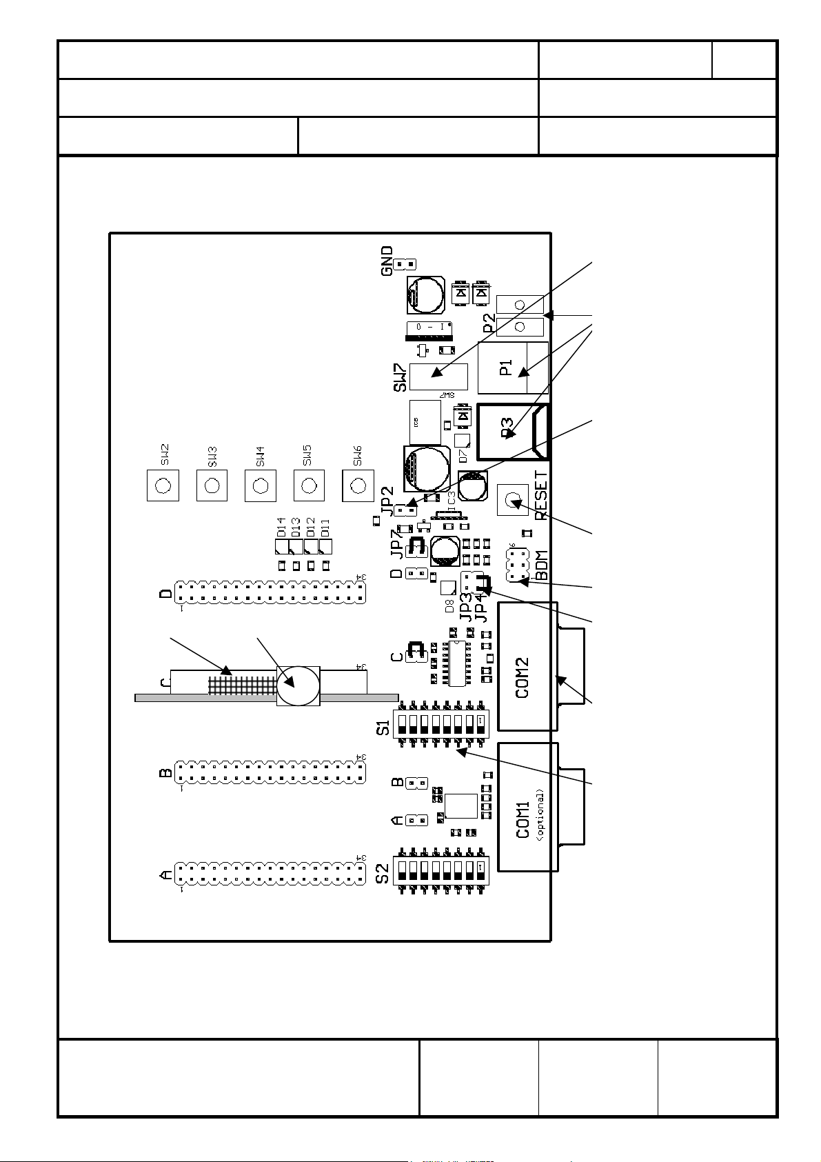
3. TESTBOARD LAYOUT
input buttons
output
LEDs
PAN4570 SMA socket
1
EvalBoard PAN4570 PAGE
Seite 5 of 20
PANASONIC’S CODE
No.
DS-Eval4570-2400
DATE
Datum
06.11.2006
power switch
power supply
inputs 7-9Vdc
JP2 for
connecting +5Vdc
to carrierboards
(not used on
PAN4570 board)
RESET button
BDM not used
Vcc voltage
selector, JP4 set
for 2,7Vdc
serial RS232
interface COM2
UART1: S1-1 and
S1-3 on, all others
off (no HW
handshake)
REV.
C
Figure 2 ISM RF Transceiver testboard with PAN4570 and antenna
European Technology Center
Panasonic Electronic Devices (EUROPE) GmbH
APPROVED
genehmigt
CHECKED
geprüft
DESIGNED
Erstellt
CLASSIFICATION
a
Einstufung
SUBJECT
Thema
CUSTOMER’S CODE
EvalPAN4570
EvalBoard PAN4570
PANASONIC’S CODE
No.
DS-Eval4570-2400
PAGE
Seite
DATE
Datum
06.11.2006
6 of 20
4. OPERATION OF THE TESTBOARD
If not already done please follow the basic setting up instructions as in Chapter 2
Check if the jumper plugs are set as indicated in Figure 2. The functions of the jumpers
are as follows:
jumper
me
function to set as in Figure 2
A Vcc for position A do not care
B Vcc for module at position B* do not care
C Vcc for module at position C* yes
D Vcc for module at position D* do not care
JP2 5Vdc feed to Slots A, B, C, D** no
JP3
JP4
JP7
Vcc setting 2.1-2.7-3.4V;
see Table 2
Vcc setting 2.1-2.7-3.4V;
see Table 2
Vcc regulator output feed
to A, B, C, D
no for
Vcc=2.7Vdc default
yes for
Vcc=2.7Vdc default
yes
(Table 1)
* Position C is used as an example, position B or D could be used as well.
An amperemeter for measuring module current can be inserted instead of the jumper
** +5Vdc supply (independent on JP3 and JP4 settings) option is provided for application
demos. The +5Vdc supply is NOT used on PAN4570 carrierboard.
Check if the port switches S1 near to the COM2 connector for RS232 are all set to off
position except the selected UART as noted in Figure 2/Table 3.
5. POWER SUPPLY
5.1. D.C. POWER FROM A POWER SUPPLY
REV.
C
Set the power switch SW7 to the position 2 = off.
Connect a power supply with 7-9VDC to one of the power inputs (P1 or P2).
In case of P1 use a plug with 5,5mm diameter and the positive terminal at the centre
contact.
European Technology Center
Panasonic Electronic Devices (EUROPE) GmbH
APPROVED
genehmigt
CHECKED
geprüft
DESIGNED
Erstellt
 Loading...