

Panasonic NV-GS120EG, NV-GS120EB, NV-GS120EGM, NV-GS120GC, NV-GS120GN Service Manual
...
gs200_v1.html
Table Of Contents
COVER
1 INTRODUCTION
1.1 INTRODUCTION
1.2 FEATURE
COMPARISON CHART
1.3 ABOUT LEAD FREE
SOLDER (PbF)
2 CAUTION FOR AC
CORD (VJA0940 TYPE)
2.1 INFORMATION FOR
YOUR SAFETY
2.2 CAUTION FOR AC
MAINS LEAD
2.2.1 Important
2.2.2 Before use
2.2.3 How to replace the
Fuse
3 HOW TO REPLACE THE
LITHIUM BATTERY
(PROCEDURE)
4 ADJUSTMENT
PROCEDURES
4.1 DISASSEMBLE FLOW
CHART
4.2 DISASSEMBLY
PROCEDURES
4.3 DISASSEMBLY
PROCEDURES MECHA.
UNIT
4.4 DISASSEMBLY
PROCEDURES OF CAMERA
LENS UNIT
5 SERVICE CAUTION
5.1 HOW TO DISCHARGE
THE CAPACITOR ON
FRONT C.B.A.
5.2 EEPROM DATA FOR
SPARE PARTS OF THE
MAIN C.B.A.
5.3 SERVICE EXTENSION
CABLES.
5.4 LOCATION FOR
SPARE CONNECTORS OF
THE MAIN C.B.A. & SUB C.
B.A.
5.4.1 MAIN C.B.A.
5.4.2 SUB C.B.A. (NVGS120 ONLY)
5.4.3 SUB C.B.A. (NVGS200 ONLY)
6 ELECTRICAL
Service Manual
TOP NEXT
ORDER NO.VM0403012C8
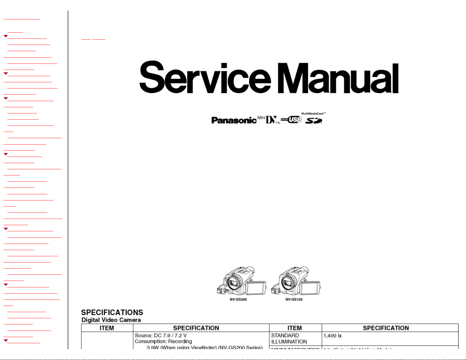
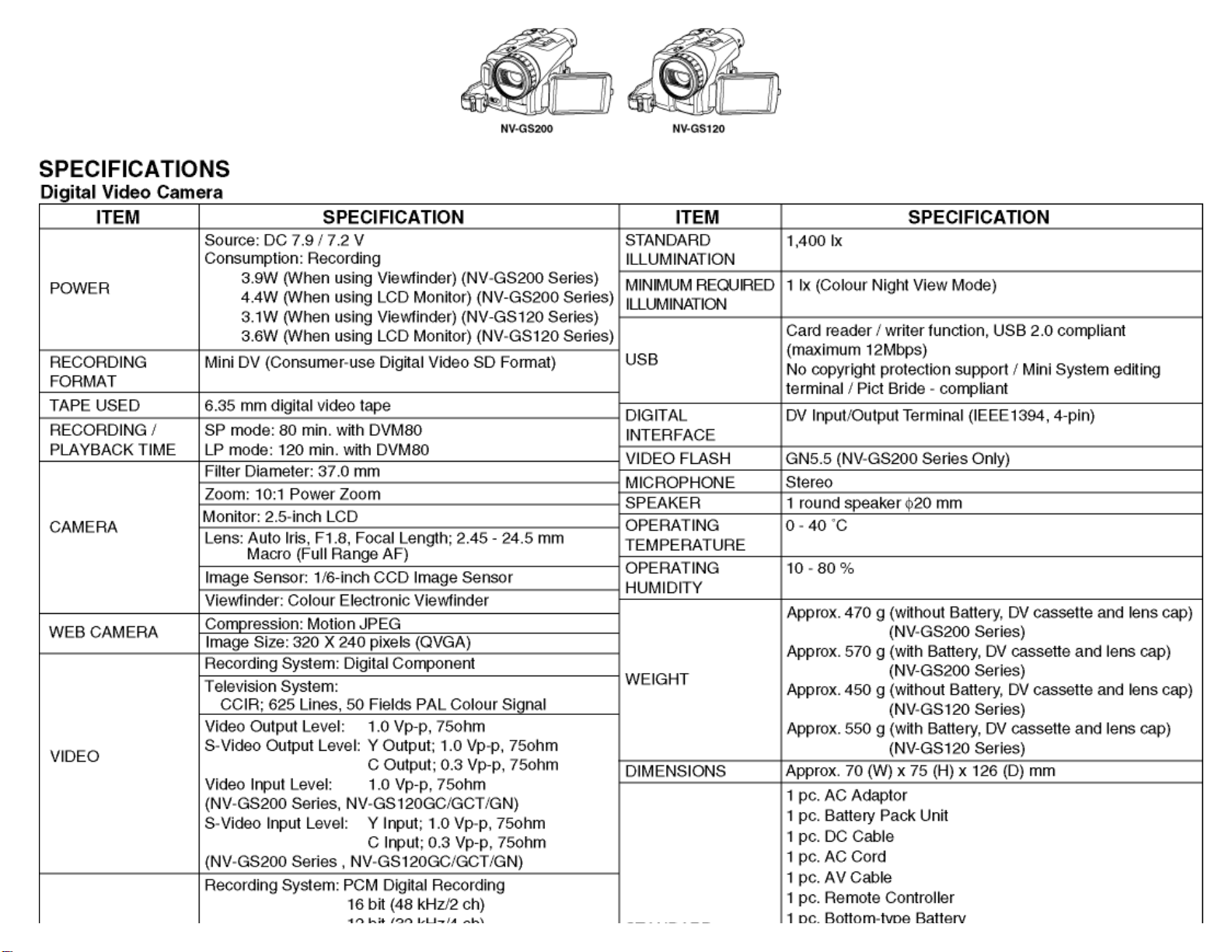
Digital Video Camera/Recorder
● NV-GS120EG
NV-GS120EB
NV-GS120EGM
NV-GS120GC
NV-GS120GN
NV-GS120GCT
❍ NV-GS200EG
NV-GS200EB
NV-GS200EGM
NV-GS200GC
NV-GS200GN
NV-GS200GCT
VOL.1
A-MECHANISM
Colour
(S)....................Silver Type
http://202.224.189.178/~sgml/viewing/NV-GS120EG/ALL/SVC/PVAccel.html (1 of 4)8/14/2004 6:43:07 PM
gs200_v1.html
ADJUSTMENT
PROCEDURES
6.1 COMPUTER ASSISTED
ADJUSTMENT SYSTEM <
TATSUJIN > ADJUSTMENT.
6.2 SET-UP MANUAL FOR
DV-Camcorder.
6.3 SET UP PC-EVR
ADJUSTMENT PROGRAM
6.4 INITIAL GUIDELINE
7 MECHANICAL
ADJUSTMENT
PROCEDURES
7.1 ADJUSTMENT ITEM
7.2 ADJUSTMENT
PROCEDURES
8 SERVICE MODE
8.1 ERROR DISPLAY
8.2 SERVICE MENU
9 WAVEFORM TABLE
10 SCHEMATIC
DIAGRAM
10.1 OVERALL
SCHEMATIC DIAGRAM
10.2 INTERCONNECTION
SCHEMATIC DIAGRAM
10.3 SIDE (L) SCHEMATIC
DIAGRAM
10.4 CASSETTE COVER
UNIT SCHEMATIC
DIAGRAM
10.5 REAR OPERATION
SCHEMATIC DIAGRAM
10.6 SIDE (R) / R
RELAY / LCD DET /
SD OPEN SCHEMATIC
DIAGRAM
10.7 SIDE (R) VTR
OPERATION UNIT
SCHEMATIC DIAGRAM
10.8 MF SENSOR
SCHEMATIC DIAGRAM
(NV-GS200SERIES ONLY)
10.9 EVF SCHEMATIC
DIAGRAM
10.10 PL FLEX. CARD
SCHEMATIC DIAGRAM
10.11 SD HOLDER
SCHEMATIC DIAGRAM
10.12 CCD FLEX. CARD
SCHEMATIC DIAGRAM
10.13 FRONT / FLASH
SW FLEX. CARD
http://202.224.189.178/~sgml/viewing/NV-GS120EG/ALL/SVC/PVAccel.html (2 of 4)8/14/2004 6:43:07 PM
gs200_v1.html
SCHEMATIC DIAGRAM
10.14 JACK SCHEMATIC
DIAGRAM
10.15 MONITOR
SCHEMATIC DIAGRAM
(NV-GS120SERIES ONLY)
10.16 MONITOR
SCHEMATIC DIAGRAM
(NV-GS200SERIES ONLY)
11 CIRCUIT BOARD
ASSEMBLIES
11.1 SIDE (L) C.B.A.
11.2 EVF C.B.A.
11.3 FLASH SW C.B.A.
(NV-GS200SERIES ONLY)
11.4 SD OPEN C.B.A.
11.5 SIDE (R) (LCD DET) C.
B.A.
11.6 SIDE (R) (R RELAY) C.
B.A.
11.7 SD HOLDER C.B.A.
11.8 JACK C.B.A.
11.9 CCD FLEX. CARD C.
B.A.
11.10 FRONT C.B.A.
11.11 MONITOR C.B.A.
(NV-GS120SERIES ONLY)
11.12 MONITOR C.B.A.
(NV-GS200SERIES ONLY)
12 EXPLODED VIEWS
12.1 FRAME & CASING
SECTION (1)
12.2 FRAME & CASING
SECTION (2)
12.3 LCD SECTION
12.4 CAMERA LENS
SECTION
12.5 VCR MECHANISM
SECTION
12.6 PACKING PARTS &
ACCESSORIES SECTION
13 REPLACEMENT PARTS
LIST
13.1 FRAME & CASING
SECTION (1), (2) PARTS
LIST
13.2 LCD SECTION PARTS
LIST
13.3 CAMERA LENS
SECTION PARTS LIST
13.4 VCR MECHANISM
SECTION PARTS LIST
13.5 PACKING PARTS &
© 2004 Matsushita Electric Industrial Co., Ltd. All rights reserved. Unauthorized copying and distribution is a violation of law.
TOP NEXT
http://202.224.189.178/~sgml/viewing/NV-GS120EG/ALL/SVC/PVAccel.html (3 of 4)8/14/2004 6:43:07 PM

gs200_v1.html
ACCESSORIES SECTION
PARTS LIST
13.6 ELECTRICAL
REPLACEMENT PARTS
LIST
14 Schematic Diagram for
printing with A4 size
http://202.224.189.178/~sgml/viewing/NV-GS120EG/ALL/SVC/PVAccel.html (4 of 4)8/14/2004 6:43:07 PM

http://202.224.189.178/~sgml/viewing/NV-GS120EG/ALL/SVC/gs200_v1.html
Table Of Contents
COVER
1 INTRODUCTION
1.1 INTRODUCTION
1.2 FEATURE COMPARISON CHART
1.3 ABOUT LEAD FREE SOLDER (PbF)
2 CAUTION FOR AC CORD (VJA0940 TYPE)
2.1 INFORMATION FOR YOUR SAFETY
2.2 CAUTION FOR AC MAINS LEAD
2.2.1 Important
2.2.2 Before use
2.2.3 How to replace the Fuse
3 HOW TO REPLACE THE LITHIUM BATTERY (PROCEDURE)
4 ADJUSTMENT PROCEDURES
4.1 DISASSEMBLE FLOW CHART
4.2 DISASSEMBLY PROCEDURES
4.3 DISASSEMBLY PROCEDURES MECHA. UNIT
4.4 DISASSEMBLY PROCEDURES OF CAMERA LENS UNIT
5 SERVICE CAUTION
http://202.224.189.178/~sgml/viewing/NV-GS120EG/ALL/SVC/gs200_v1.html (1 of 5)8/14/2004 6:43:08 PM

http://202.224.189.178/~sgml/viewing/NV-GS120EG/ALL/SVC/gs200_v1.html
5.1 HOW TO DISCHARGE THE CAPACITOR ON FRONT C.B.A.
5.2 EEPROM DATA FOR SPARE PARTS OF THE MAIN C.B.A.
5.3 SERVICE EXTENSION CABLES.
5.4 LOCATION FOR SPARE CONNECTORS OF THE MAIN C.B.A. & SUB C.B.A.
5.4.1 MAIN C.B.A.
5.4.2 SUB C.B.A. (NV-GS120 ONLY)
5.4.3 SUB C.B.A. (NV-GS200 ONLY)
6 ELECTRICAL ADJUSTMENT PROCEDURES
6.1 COMPUTER ASSISTED ADJUSTMENT SYSTEM < TATSUJIN > ADJUSTMENT.
6.2 SET-UP MANUAL FOR DV-Camcorder.
6.3 SET UP PC-EVR ADJUSTMENT PROGRAM
6.4 INITIAL GUIDELINE
7 MECHANICAL ADJUSTMENT PROCEDURES
7.1 ADJUSTMENT ITEM
7.2 ADJUSTMENT PROCEDURES
8 SERVICE MODE
8.1 ERROR DISPLAY
8.2 SERVICE MENU
9 WAVEFORM TABLE
http://202.224.189.178/~sgml/viewing/NV-GS120EG/ALL/SVC/gs200_v1.html (2 of 5)8/14/2004 6:43:08 PM

http://202.224.189.178/~sgml/viewing/NV-GS120EG/ALL/SVC/gs200_v1.html
10 SCHEMATIC DIAGRAM
10.1 OVERALL SCHEMATIC DIAGRAM
10.2 INTERCONNECTION SCHEMATIC DIAGRAM
10.3 SIDE (L) SCHEMATIC DIAGRAM
10.4 CASSETTE COVER UNIT SCHEMATIC DIAGRAM
10.5 REAR OPERATION SCHEMATIC DIAGRAM
10.6 SIDE (R) / R RELAY / LCD DET / SD OPEN SCHEMATIC DIAGRAM
10.7 SIDE (R) VTR OPERATION UNIT SCHEMATIC DIAGRAM
10.8 MF SENSOR SCHEMATIC DIAGRAM (NV-GS200SERIES ONLY)
10.9 EVF SCHEMATIC DIAGRAM
10.10 PL FLEX. CARD SCHEMATIC DIAGRAM
10.11 SD HOLDER SCHEMATIC DIAGRAM
10.12 CCD FLEX. CARD SCHEMATIC DIAGRAM
10.13 FRONT / FLASH SW FLEX. CARD SCHEMATIC DIAGRAM
10.14 JACK SCHEMATIC DIAGRAM
10.15 MONITOR SCHEMATIC DIAGRAM (NV-GS120SERIES ONLY)
10.16 MONITOR SCHEMATIC DIAGRAM (NV-GS200SERIES ONLY)
11 CIRCUIT BOARD ASSEMBLIES
11.1 SIDE (L) C.B.A.
http://202.224.189.178/~sgml/viewing/NV-GS120EG/ALL/SVC/gs200_v1.html (3 of 5)8/14/2004 6:43:08 PM

http://202.224.189.178/~sgml/viewing/NV-GS120EG/ALL/SVC/gs200_v1.html
11.2 EVF C.B.A.
11.3 FLASH SW C.B.A. (NV-GS200SERIES ONLY)
11.4 SD OPEN C.B.A.
11.5 SIDE (R) (LCD DET) C.B.A.
11.6 SIDE (R) (R RELAY) C.B.A.
11.7 SD HOLDER C.B.A.
11.8 JACK C.B.A.
11.9 CCD FLEX. CARD C.B.A.
11.10 FRONT C.B.A.
11.11 MONITOR C.B.A. (NV-GS120SERIES ONLY)
11.12 MONITOR C.B.A. (NV-GS200SERIES ONLY)
12 EXPLODED VIEWS
12.1 FRAME & CASING SECTION (1)
12.2 FRAME & CASING SECTION (2)
12.3 LCD SECTION
12.4 CAMERA LENS SECTION
12.5 VCR MECHANISM SECTION
12.6 PACKING PARTS & ACCESSORIES SECTION
13 REPLACEMENT PARTS LIST
PV
http://202.224.189.178/~sgml/viewing/NV-GS120EG/ALL/SVC/gs200_v1.html (4 of 5)8/14/2004 6:43:08 PM

http://202.224.189.178/~sgml/viewing/NV-GS120EG/ALL/SVC/gs200_v1.html
13.1 FRAME & CASING SECTION (1), (2) PARTS LIST
13.2 LCD SECTION PARTS LIST
13.3 CAMERA LENS SECTION PARTS LIST
13.4 VCR MECHANISM SECTION PARTS LIST
13.5 PACKING PARTS & ACCESSORIES SECTION PARTS LIST
13.6 ELECTRICAL REPLACEMENT PARTS LIST
14 Schematic Diagram for printing with A4 size
http://202.224.189.178/~sgml/viewing/NV-GS120EG/ALL/SVC/gs200_v1.html (5 of 5)8/14/2004 6:43:08 PM
http://202.224.189.178/~sgml/viewing/NV-GS120EG/ALL/SVC/s0000000000.html
Service Manual
TOP NEXT
ORDER NO.VM0403012C8
Digital Video Camera/Recorder
● NV-GS120EG
NV-GS120EB
NV-GS120EGM
NV-GS120GC
NV-GS120GN
NV-GS120GCT
❍ NV-GS200EG
NV-GS200EB
NV-GS200EGM
NV-GS200GC
NV-GS200GN
NV-GS200GCT
VOL.1
A-MECHANISM
Colour
(S)....................Silver Type
http://202.224.189.178/~sgml/viewing/NV-GS120EG/ALL/SVC/s0000000000.html (1 of 3)8/14/2004 6:43:08 PM
http://202.224.189.178/~sgml/viewing/NV-GS120EG/ALL/SVC/s0000000000.html
http://202.224.189.178/~sgml/viewing/NV-GS120EG/ALL/SVC/s0000000000.html (2 of 3)8/14/2004 6:43:08 PM
http://202.224.189.178/~sgml/viewing/NV-GS120EG/ALL/SVC/s0000000000.html
© 2004 Matsushita Electric Industrial Co., Ltd. All rights reserved. Unauthorized copying and distribution is a violation of law.
TOP NEXT
http://202.224.189.178/~sgml/viewing/NV-GS120EG/ALL/SVC/s0000000000.html (3 of 3)8/14/2004 6:43:08 PM

http://202.224.189.178/~sgml/viewing/NV-GS120EG/ALL/SVC/s0100000000x.html
1 INTRODUCTION
TOP PREVIOUS NEXT
1.1 INTRODUCTION
1.2 FEATURE COMPARISON CHART
1.3 ABOUT LEAD FREE SOLDER (PbF)
TOP PREVIOUS NEXT
http://202.224.189.178/~sgml/viewing/NV-GS120EG/ALL/SVC/s0100000000x.html8/14/2004 6:43:09 PM

http://202.224.189.178/~sgml/viewing/NV-GS120EG/ALL/SVC/s0101000000.html
1.1 INTRODUCTION
TOP PREVIOUS NEXT
This service manual contains technical information which will allow service personnel´s to understand
and service this model.Please place orders using the parts list and not the drawing reference numbers.
If the circuit is changed or modified, this information will be followed by supplement service manual to
be filed with original service manual.
Note 1:
These movie camera uses AC Adaptor VSK0651.
Note 2:
1) This service manual does not contain the following information, because of the impossibility of
sevicing at component level.
1. Schematic Diagram, Block Diagram and C.B.A. layout of Main C.B.A./ Sub C.B.A.
2. Parts List for individual parts of Main C.B.A./ Sub C.B.A.
2) The following category is/are recycle module part. Please send it/them to Central Repair Center.
*Main C.B.A. (VEP03G57B: NV-GS200 SERIES, VEP03G57F: NV-GS120EG/EB/EGM,
VEP03G57G: NV-GS120GC/GN/
GCT)
*Sub C.B.A. (VEP23599B: NV-GS200 SERIES, VEP23602B: NV-GS120 SERIES)
When a part replacement is required for repairing each Main C.B.A., replace the assembly parts.
(Main C.B.A. and Sub C.B.A.)
The following circuits are contained in Main C.B.A.
1. Main Connection Circuit
http://202.224.189.178/~sgml/viewing/NV-GS120EG/ALL/SVC/s0101000000.html (1 of 2)8/14/2004 6:43:10 PM

http://202.224.189.178/~sgml/viewing/NV-GS120EG/ALL/SVC/s0101000000.html
2. AVIO Circuit
3. EX Input Circuit
4. LCD Circuit
5. Drive Circuit
6. Video Circuit
7. Power Circuit
8. Control Circuit
The following circuits are contained in Sub C.B.A.
1. Sub Connection Circuit
2. Sub Power Circuit
3. MPEG Circuit
4. Lens Drive Circuit
5. Camera Circuit
TOP PREVIOUS NEXT
http://202.224.189.178/~sgml/viewing/NV-GS120EG/ALL/SVC/s0101000000.html (2 of 2)8/14/2004 6:43:10 PM
http://202.224.189.178/~sgml/viewing/NV-GS120EG/ALL/SVC/s0102000000.html
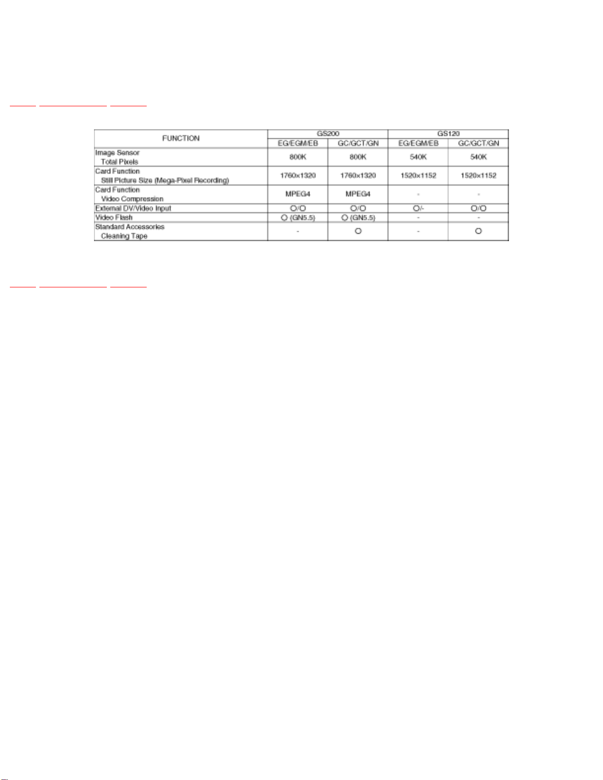
1.2 FEATURE COMPARISON CHART
TOP PREVIOUS NEXT
TOP PREVIOUS NEXT
http://202.224.189.178/~sgml/viewing/NV-GS120EG/ALL/SVC/s0102000000.html8/14/2004 6:43:11 PM
http://202.224.189.178/~sgml/viewing/NV-GS120EG/ALL/SVC/s0103000000.html
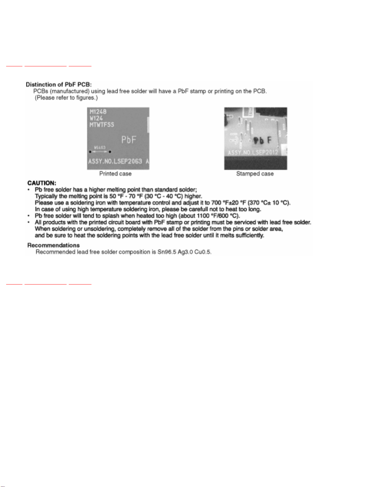
1.3 ABOUT LEAD FREE SOLDER (PbF)
TOP PREVIOUS NEXT
TOP PREVIOUS NEXT
http://202.224.189.178/~sgml/viewing/NV-GS120EG/ALL/SVC/s0103000000.html8/14/2004 6:43:13 PM

http://202.224.189.178/~sgml/viewing/NV-GS120EG/ALL/SVC/s0200000000x.html
2 CAUTION FOR AC CORD (VJA0940 TYPE)
TOP PREVIOUS NEXT
2.1 INFORMATION FOR YOUR SAFETY
2.2 CAUTION FOR AC MAINS LEAD
2.2.1 Important
2.2.2 Before use
2.2.3 How to replace the Fuse
TOP PREVIOUS NEXT
http://202.224.189.178/~sgml/viewing/NV-GS120EG/ALL/SVC/s0200000000x.html8/14/2004 6:43:13 PM

http://202.224.189.178/~sgml/viewing/NV-GS120EG/ALL/SVC/s0201000000.html
2.1 INFORMATION FOR YOUR SAFETY
TOP PREVIOUS NEXT
IMPORTANT
Your attention is drawn to the fact that recording of pre-recorded tapes or discs or other published or
broadcast material may infringe copyright laws.
WARNING
To reduce the risk of fire or shock hazard, do not expose this equipment to rain or moisture.
CAUTION
To reduce the risk of fire or shock hazard and annoying interference, use the recommended accessories
only.
FOR YOUR SAFETY
DO NOT REMOVE THE OUTER COVER
To prevent electric shock, do not remove the cover. No user serviceable parts inside. Refer servicing to
qualified service personnel.
TOP PREVIOUS NEXT
http://202.224.189.178/~sgml/viewing/NV-GS120EG/ALL/SVC/s0201000000.html8/14/2004 6:43:14 PM
http://202.224.189.178/~sgml/viewing/NV-GS120EG/ALL/SVC/s0202000000.html
2.2 CAUTION FOR AC MAINS LEAD
TOP PREVIOUS NEXT
For your safety, please read the following text carefully.
This appliance is supplied with a moulded three-pin mains plug for your safety and convenience.
A 5-ampere fuse is fitted in this plug.
Should the fuse need to be replaced please ensure that the replacement fuse has a rating of 5 amperes
and it is approved by ASTA or BSI to BS1362
Check for the ASRA mark or the BSI mark on the body of the fuse.
If the plug contains a removable fuse cover you must ensure that it is refitted when the fuse is replaced.
If you lose the fuse cover, the plug must not be used until a replacement cover is obtained.
A replacement fuse cover can be purchased from your local Panasonic Dealer.
If the fitted moulded plug is unsuitable for the socket outlet in your home then the fuse should be
removed and the plug cut off and disposed of safety.
There is a danger of severe electrical shock if the cut off plug is inserted into any 13-ampere socket.
If a new plug is to be fitted please observe the wiring code as shown below.
If in any doubt, please consult a qualified electrician.
2.2.1 Important
2.2.2 Before use
2.2.3 How to replace the Fuse
http://202.224.189.178/~sgml/viewing/NV-GS120EG/ALL/SVC/s0202000000.html (1 of 2)8/14/2004 6:43:15 PM

http://202.224.189.178/~sgml/viewing/NV-GS120EG/ALL/SVC/s0202000000.html
TOP PREVIOUS NEXT
http://202.224.189.178/~sgml/viewing/NV-GS120EG/ALL/SVC/s0202000000.html (2 of 2)8/14/2004 6:43:15 PM
http://202.224.189.178/~sgml/viewing/NV-GS120EG/ALL/SVC/s0202010000.html
2.2.1 Important
TOP PREVIOUS NEXT
The wires in this mains lead are coloured in accordance with the following code:
Blue Neutral
Brown Live
As the colours of the wires in the mains lead of this appliance may not correspond with the coloured
markings identifying the terminals in your plug, proceed as follows:The wire which is coloured BLUE
must be connected to the terminal in the plug which is marked with the letter N or coloured BLACK.The
wire which is coloured BROWN must be connected to the terminal in the plug which is marked with the
letter L or coloured RED.Under no circumstances should either of these wires be connected to the earth
terminal of the three pin plug, marked with the letter E or the Earth Symbol.
TOP PREVIOUS NEXT
http://202.224.189.178/~sgml/viewing/NV-GS120EG/ALL/SVC/s0202010000.html8/14/2004 6:43:16 PM
http://202.224.189.178/~sgml/viewing/NV-GS120EG/ALL/SVC/s0202020000.html
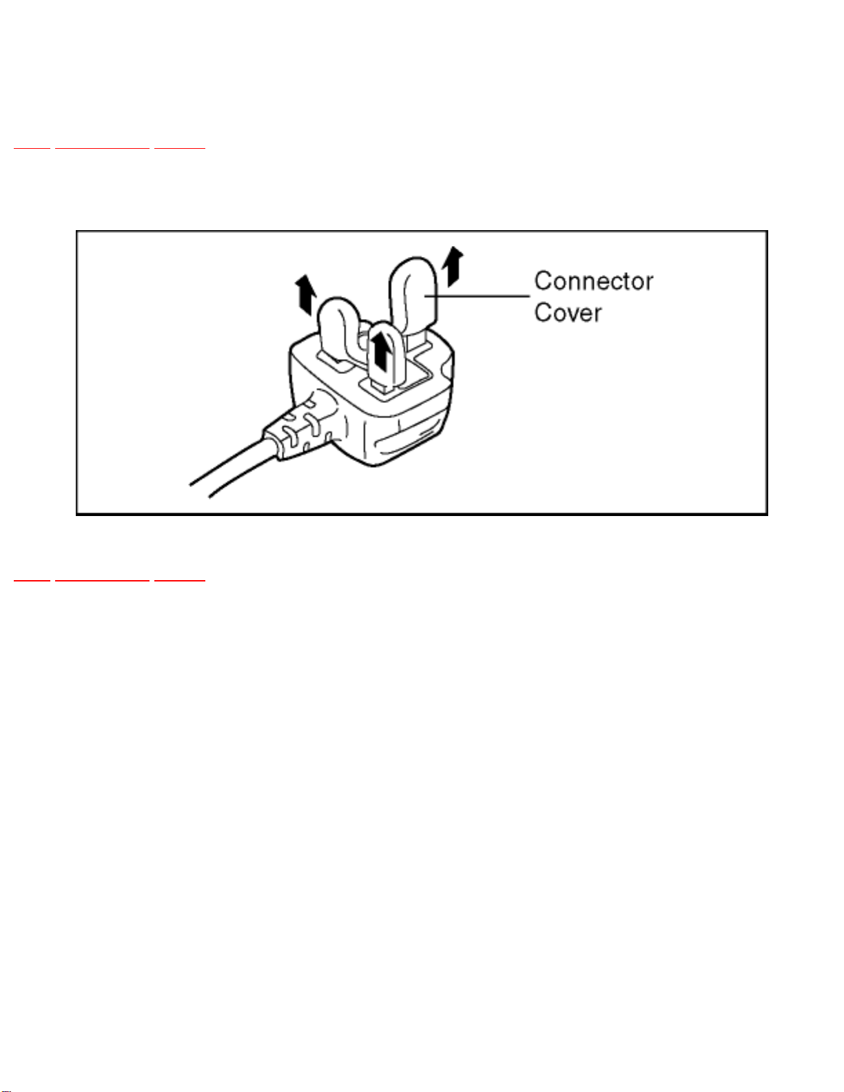
2.2.2 Before use
TOP PREVIOUS NEXT
remove the Connector Cover as follows.
TOP PREVIOUS NEXT
http://202.224.189.178/~sgml/viewing/NV-GS120EG/ALL/SVC/s0202020000.html8/14/2004 6:43:17 PM
http://202.224.189.178/~sgml/viewing/NV-GS120EG/ALL/SVC/s0202030000.html
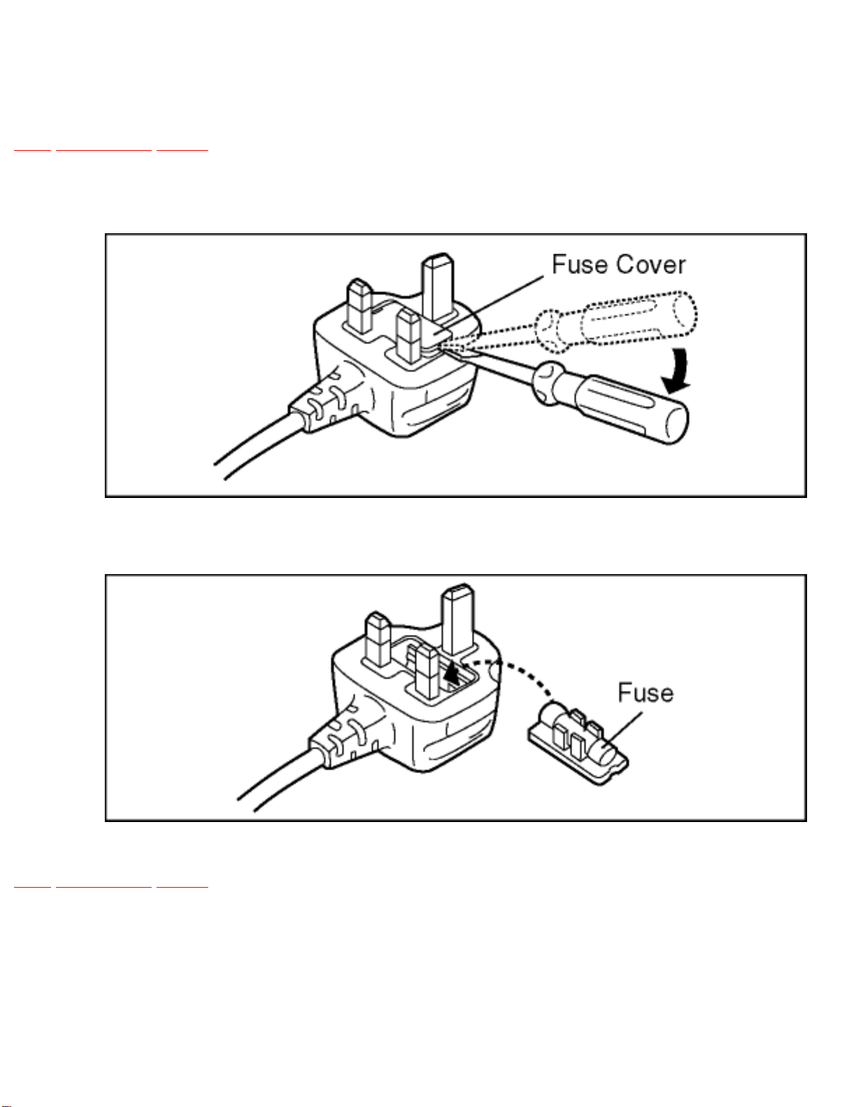
2.2.3 How to replace the Fuse
TOP PREVIOUS NEXT
1. Remove the Fuse Cover with a screwdriver.
2. Replace the fuse and attach the Fuse cover.
TOP PREVIOUS NEXT
http://202.224.189.178/~sgml/viewing/NV-GS120EG/ALL/SVC/s0202030000.html8/14/2004 6:43:18 PM
http://202.224.189.178/~sgml/viewing/NV-GS120EG/ALL/SVC/s0300000000x.html
3 HOW TO REPLACE THE LITHIUM BATTERY (PROCEDURE)
TOP PREVIOUS NEXT
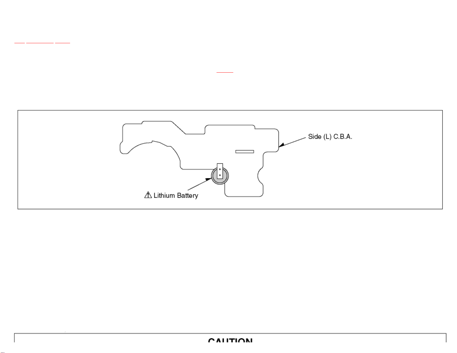
1. Remove the Side Case (L) C.B.A.. (Refer to Disassembly Procedures.)
2. Unsolder the Lithium Battery “ML-621S/F9D” and then replace the new one. (See
Fig. B1 .)
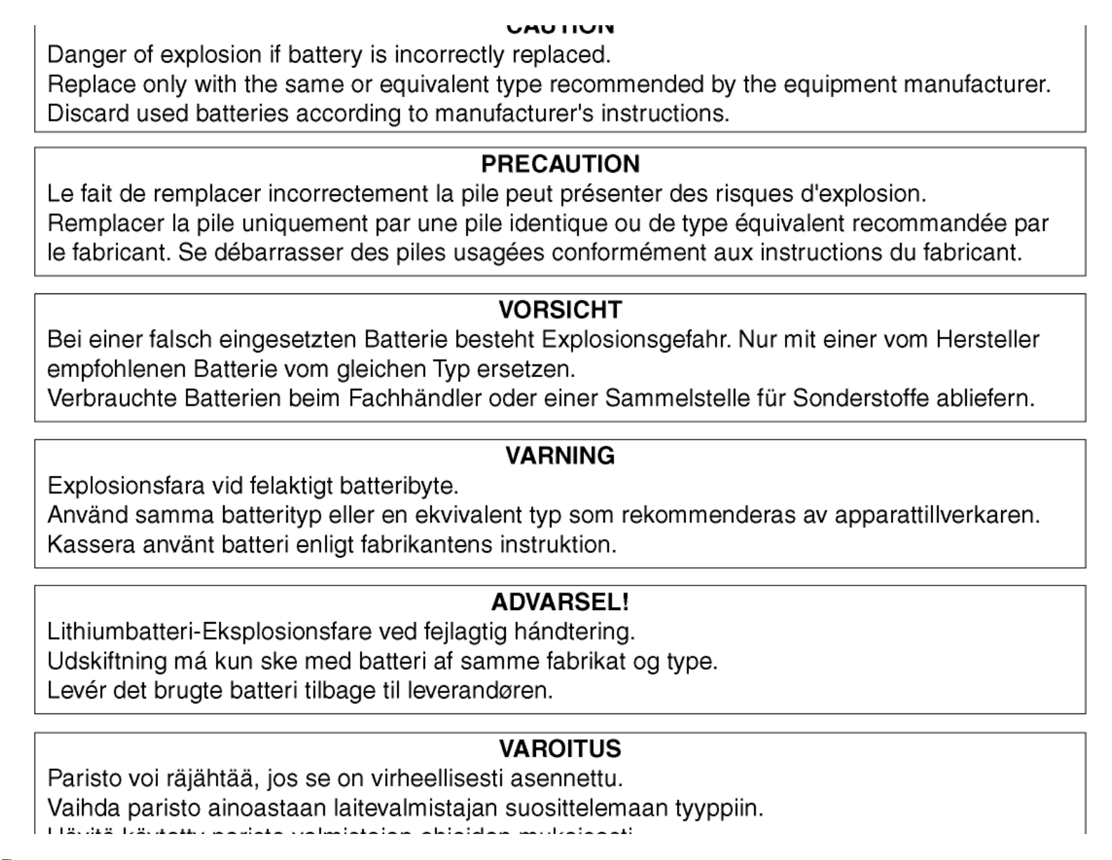
3. Danger of explosion if battery is incorrectly replaced. Replace only with the same or equivalent type.
Fig. B1
Note:
The lithium battery is a critical component. (Type No.: ML-621S/F9D Manufactured by Panasonic.)
It must never be subjected to excessive heat or discharge.
It must therefore only be fitted in equipment designed specifically for its use.
Replacement batteries must be of the same type and manufacture.
They must be fitted in the same manner and location as the original battery, with the correct polarity contacts observed.
Do not attempt to re-charge the old battery or re-use it for any other purpose.
It should be disposed of in waste products destined for burial rather than incineration.
http://202.224.189.178/~sgml/viewing/NV-GS120EG/ALL/SVC/s0300000000x.html (1 of 3)8/14/2004 6:43:21 PM
http://202.224.189.178/~sgml/viewing/NV-GS120EG/ALL/SVC/s0300000000x.html
http://202.224.189.178/~sgml/viewing/NV-GS120EG/ALL/SVC/s0300000000x.html (2 of 3)8/14/2004 6:43:21 PM
http://202.224.189.178/~sgml/viewing/NV-GS120EG/ALL/SVC/s0300000000x.html
TOP PREVIOUS NEXT
http://202.224.189.178/~sgml/viewing/NV-GS120EG/ALL/SVC/s0300000000x.html (3 of 3)8/14/2004 6:43:21 PM

http://202.224.189.178/~sgml/viewing/NV-GS120EG/ALL/SVC/s0400000000x.html
4 ADJUSTMENT PROCEDURES
TOP PREVIOUS NEXT
4.1 DISASSEMBLE FLOW CHART
4.2 DISASSEMBLY PROCEDURES
4.3 DISASSEMBLY PROCEDURES MECHA. UNIT
4.4 DISASSEMBLY PROCEDURES OF CAMERA LENS UNIT
TOP PREVIOUS NEXT
http://202.224.189.178/~sgml/viewing/NV-GS120EG/ALL/SVC/s0400000000x.html8/14/2004 6:43:22 PM
http://202.224.189.178/~sgml/viewing/NV-GS120EG/ALL/SVC/s0401000000.html
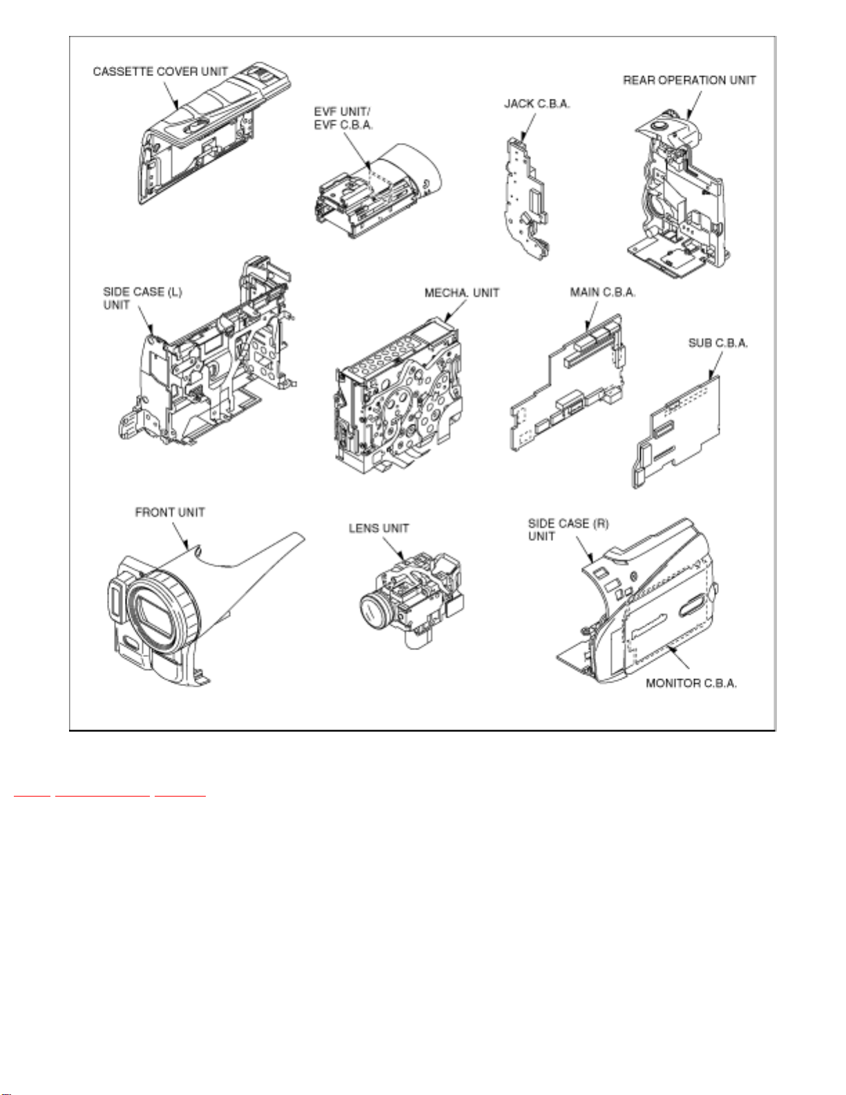
4.1 DISASSEMBLE FLOW CHART
TOP PREVIOUS NEXT
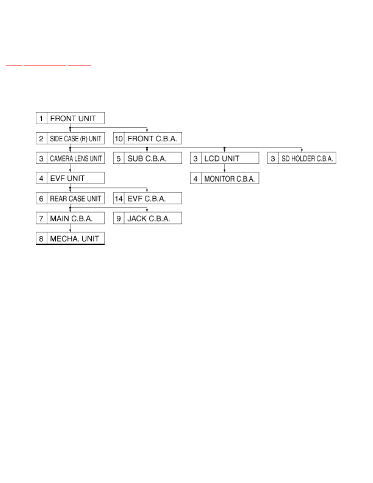
This flow chart indicates the disassembly steps the cabinet parts, C.B.A. and Mecha. Unit in order to
access to be serviced. When reinstalling, perform the steps in the reverse order.
Fig. F1
http://202.224.189.178/~sgml/viewing/NV-GS120EG/ALL/SVC/s0401000000.html (1 of 2)8/14/2004 6:43:24 PM
http://202.224.189.178/~sgml/viewing/NV-GS120EG/ALL/SVC/s0401000000.html
TOP PREVIOUS NEXT
http://202.224.189.178/~sgml/viewing/NV-GS120EG/ALL/SVC/s0401000000.html (2 of 2)8/14/2004 6:43:24 PM
 Loading...