

Panasonic NN-T985SF, NN-T994SFR, NN-T965SF, NN-T955SF, NN-T964SFR User Manual
...
ORDER NO.PHAMOS0501005A7
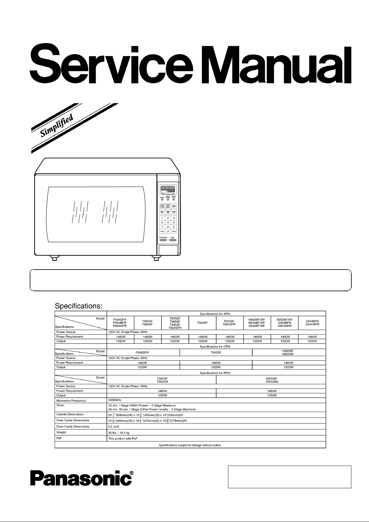
Microwave Oven
NN-P994SFR
NN-P994BFR
NN-P994WFR NN-T995
NN-T985SF NN-T975SF
NN-T965SF NN-T955SF
NN-T945SF NN-T935SF
NN-T994SFR NN-T964SFR
NN-H965 NN-S955
NN-H935 NN-S935
E1
NN-S954BFR NN-S954WFR
NN-S934BFR NN-S934WFR
APH(USA)
CPH(CANADA)
RPH(Mexico/Latin American)
Please file and use this specified manual together with the service manual for Model NN-T695 (ORDER NO.
PHAMOS0501001C1).
© 2005 Panasonic Home Appliances Microwave
Oven (Shanghai) Co., Ltd. All rights reserved.
Unauthorized copying and distribution is a violation
of law.

NN-P994SFR / NN-P994BFR
2
NN-P994SFR / NN-P994BFR
3

NN-P994SFR / NN-P994BFR
CONTENTS
Page Page
1 SCHEMATIC DIAGRAM 5
1.1. APH
1.2. CPH
1.3. RPH
2 MEASUREMENTS AND ADJUSTMENTS
2.1. Adjustment of primary latch switch, secondary latch switch
and short switch.
2.2. Measurement of microwave output
3 PROCEDURE FOR MEASURING MICROWAVE ENERGY
LEAKAGE
3.1. Equipment
3.2. Procedure for measuring radiation leakage
3.3. Record keeping and notification after measurement
3.4. At least once a year, have the radiation monitor checked
for calibration by its manufacturer.
4 SIMPLE WAY OF H.V. INVERTER/MAGNETRON
TROUBLESHOUTING
5 EXPLODED VIEW AND PARTS LIST
10
11
5
6
7
8
8
8
9
9
9
9
9
5.1. EXPLODED VIEW
5.2. PARTS LIST
5.3. WIRING MATERIALS
5.4. ESCUTCHEON BASE ASSEMBLY
5.5. PACKING AND ACCESSORIES
5.6. DOOR ASSEMBLY
6 DIGITAL PROGRAMMER CIRCUIT
6.1. P994*FR APH/CPH
6.2. NN-T995SF APH/CPH, T995SF/SM RPH, T985SF APH
6.3. NN-T955SF APH, T994SFR APH
6.4. NN-T975SF/T965SF/T945SF/T935SF APH, T964SFR
APH
6.5. NN-H965 APH/CPH, H935 APH
6.6. NN-S935 APH
6.7. NN-S955 RPH, S934*FR APH
6.8. NN-S955 APH, S954*FR APH
6.9. PARTS LIST
11
12
13
14
20
21
22
22
24
26
28
30
32
34
36
38
4
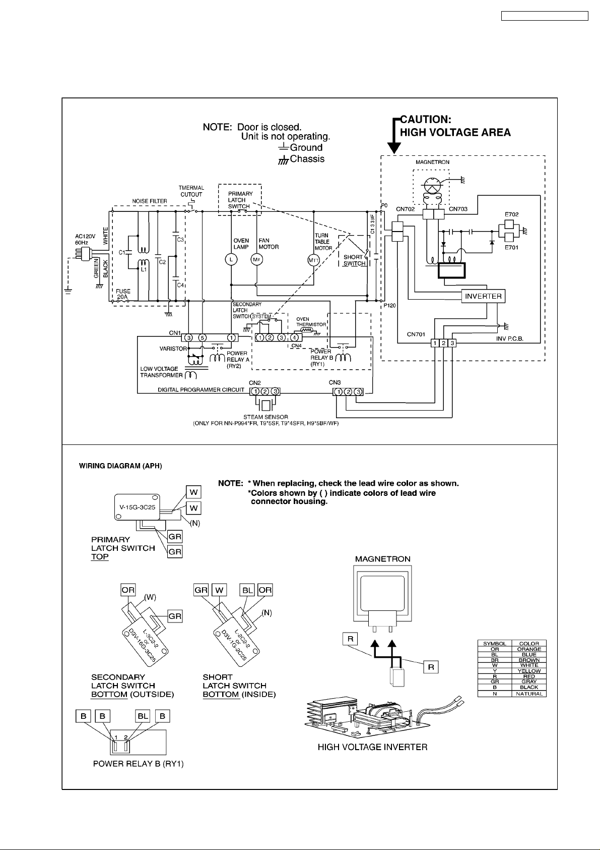
1 SCHEMATIC DIAGRAM
1.1. APH
NN-P994SFR / NN-P994BFR
5

NN-P994SFR / NN-P994BFR
1.2. CPH
6
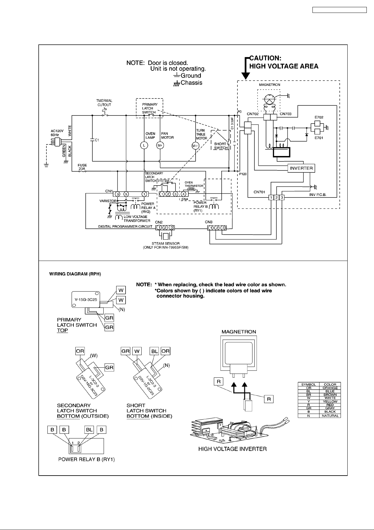
1.3. RPH
NN-P994SFR / NN-P994BFR
7
NN-P994SFR / NN-P994BFR
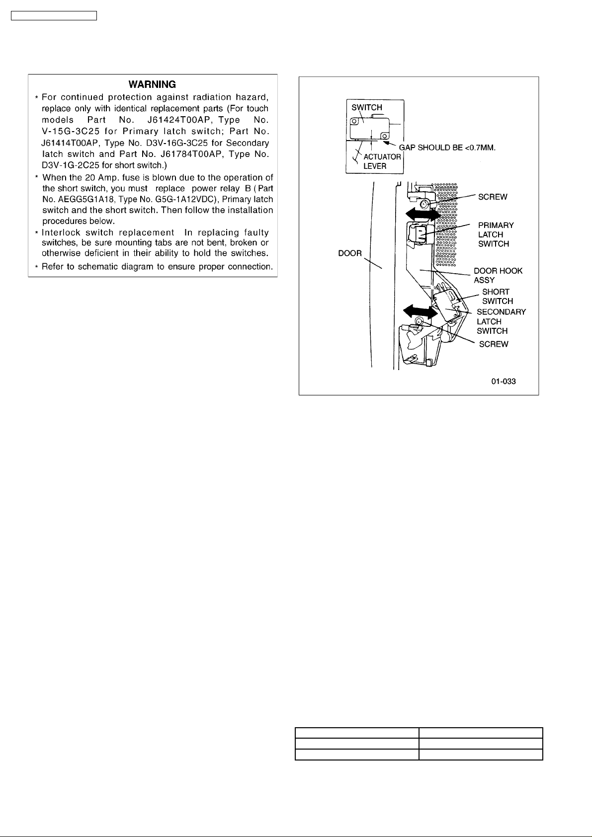
2 MEASUREMENTS AND ADJUSTMENTS
2.1. Adjustment of primary latch
switch, secondary latch switch
and short switch.
1. Mount the Primary latch switch, the Secondary latch switch
and the short switch to the door hook assembly as shown in
ILL.
NOTE:
No specific individual adjustments during
installation of the Primary latch switch, Secondary
latch switch or Short switch to the door hook are
required.
2. When mounting the door hook assembly to the oven
assembly, adjust the door hook assembly by moving it in
the direction of the arrows in the illustration so that the oven
door will not have any play in it. Check for play in the door
by pulling the door assembly. Make sure that the latch keys
move smoothly after adjustment is completed. Completely
tighten the screws holding the door hook assembly to the
oven assembly.
3. Reconnect the short switch and check the continuity of the
monitor circuit and all latch switches again by following the
component test procedures.
2.2. Measurement of microwave
output
The output power of the magnetron can be determined by
performing IEC standard test procedures. However,due to the
complexity of IEC test procedures, it is recommended to test
the magnetron using the simple method outlined below.
Necessary Equipment:
*1 liter beaker *Glass thermometer
*Wrist watch or stopwatch
NOTE:
Check the line voltage under load.Low voltage will
lower the magnetron output. Take the temperature
readings and heating time as accurately as possible.
1. Fill the beaker with exactly one liter of tap water.Stir the
water using the thermometer and record the water’s
temperature. (recorded as T1).
2. Place the beaker on the center of glass tray.
Set the oven for High power and heat it for exactly one
minute.
3. Stir the water again and read the temperature of the water.
(recorded as T2).
4. The normal temperature rise at High power level for each
model is as shown in table.
TABLE (1L-1min.test)
RATED OUTPUT TEMPERATURE RISE
1200W Min. 18.5°F(10.3°C)
1300W Min. 19.8°F(11.1°C)
8

NN-P994SFR / NN-P994BFR
3 PROCEDURE FOR MEASURING MICROWAVE ENERGY
LEAKAGE
3.2.1. Measurement with the outer panel
removed.
Whenever you replace the magnetron, measure for radiation
leakage before the outer panel is installed and after all
necessary components are replaced or adjusted. Special care
should be taken in measuring around the magnetron.
NOTE:
The U.S. Government standard is 5 mW/cm
customer’s home. 2mW/cm
voluntary standard. (1mW/cm
2
stated here is our own
2
for Canada)
2
while in the
3.1. Equipment
•
•
Electromagnatic radiation monitor
• •
•
•
Glass thermometer 212°F or 100°C
• •
•
•
600cc glass beaker
• •
3.2. Procedure for measuring
radiation leakage
Note before measuring.
•
•
Do not exceed meter full scale deflection. Leakage monitor
• •
should initially be set to the highest scale.
•
•
To prevent false readings the test probe should be held by
• •
the grip portion of the handle only and moved along the
shaded area in Figure no faster than 1 inch/sec
(2.5cm/sec).
•
•
Leakage with the outer panel removed ...... less than
• •
5mW/cm
•
•
Leakage for a fully assembled oven with door normally
• •
closed ...... less than 2mW/cm
•
•
Leakage for a fully assembled oven [Before the latch switch
• •
(primary) is interrupted] while pulling the door ...... less than
2mW/cm
1. Pour 275 ± 15cc (9ozs
water in a beaker which is graduated to 600cc, and place in
the center of the oven.
2. Set the radiation monitor to 2450MHz and use it following
the manufacturer´s recomm ended test procedure to assure
correct results.
3. When measuring the leakage, always use the 2 inch (5cm)
spacer supplied with the probe.
4. Tap the start pad or set the timer and with the magnetron
oscillating, measure the leakage by holding the probe
perpendicular to the surface being measured.
2
.
2
(1mW/cm2for Canada).
2
.
s
± 1/2oz) of 20°C ± 5°C (68° ± 9°F)
3.2.2. Measurements with a fully
assembled oven.
After all components, including outer panel are fully assembled,
measure for radiation leakage around the door periphery, the
door viewing window, the exhaust opening and air inlet
openings.
3.3. Record keeping and
notification after measurement
•
•
After any adjustment or repair to a microwave oven, a
• •
leakage reading must be taken. Record this leakage
reading on the repair ticket even if it is zero.
A copy of this repair ticket and the microwave leakage
reading should be kept by repair facility.
•
•
Should the radiation leakage be more than 2 mW/cm
• •
(1mW/cm for Canada) after determining that all parts are in
good condition, functioning properly, and genuine
replacement parts as listed in this manual have been used,
immediately notify PASC, PSC or PCI.
3.4. At least once a year, have the
radiation monitor checked for
calibration by its
manufacturer.
2
9
NN-P994SFR / NN-P994BFR
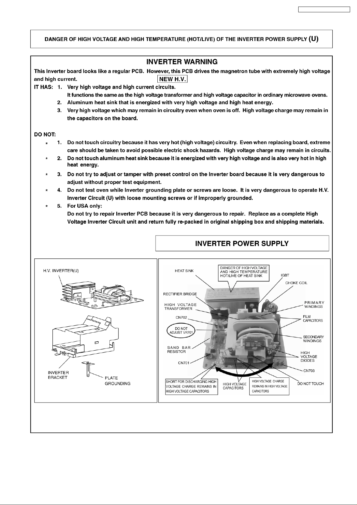
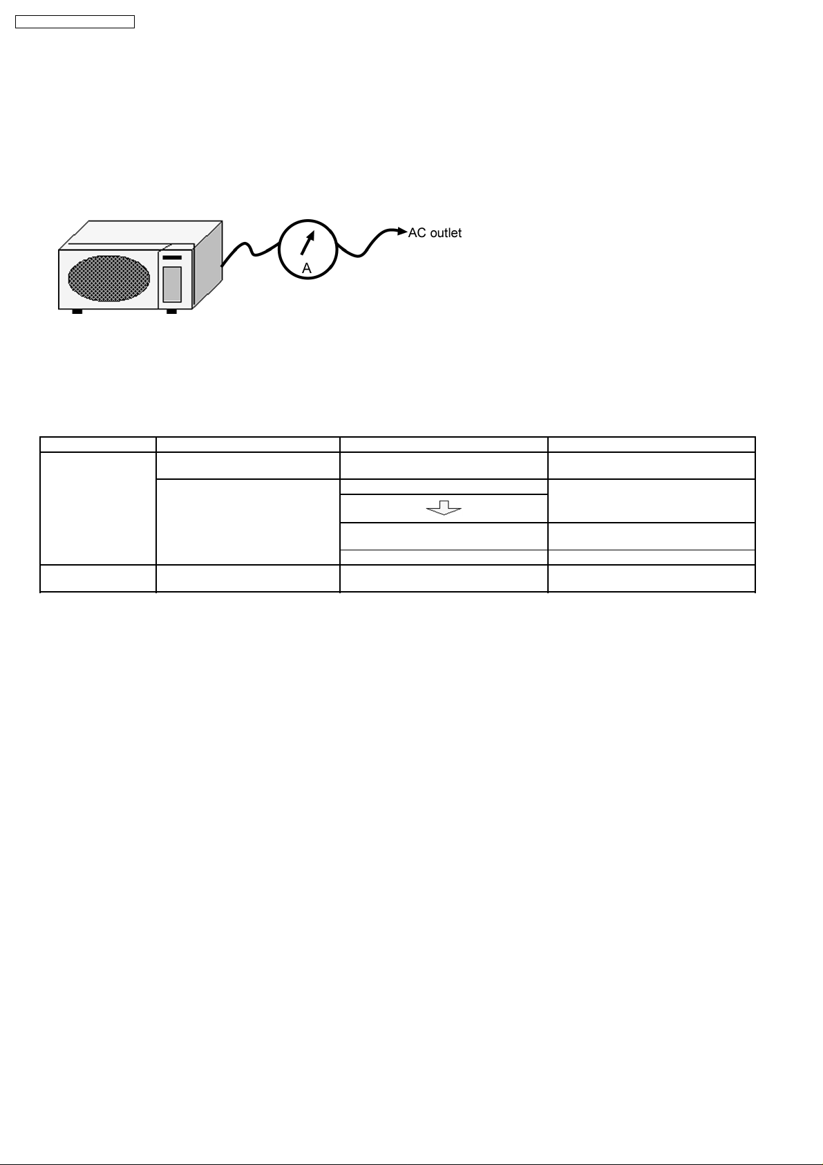
4 SIMPLE WAY OF H.V. INVERTER/MAGNETRON
TROUBLESHOUTING
Purpose:
Simple way
Set-up:
The unit under question is connected through the Ammeter as shown below.
Procedure:
Follow the matrix table below to identify the problem source.
Note:
Do not replace both Inverter board and Magnetron simultaneously and automatically without going through this
procedure.
Power will: Ammeter reading is: To do: Remedy:
Shut off in 23 seconds
after “Start”.
(3/23 seconds rule)
1. Between 0.5A and 1.0A. Check and repair open magnetron circuit Open magnetron wiring between Inverter
2. Between 1.0A and 2.0A. Check continuity of D702 in Inverter PCB.
of identifying whether it’s Magnetron, Inverter, or others.
and magnetron terminal.
Shut off in 3 seconds
after “Start”
1. D702 shorted Replace
2. D702 is OK Replace
1. Less than 0.5A Check open circuit: Latch Switch, DPC,
Power Relay and CN701
(F606Y6G00AP/F606Y6G00CP)
H.V.Inverter
magnetron
Replace defective component(s), or
correct switch, cables and connectors.
10
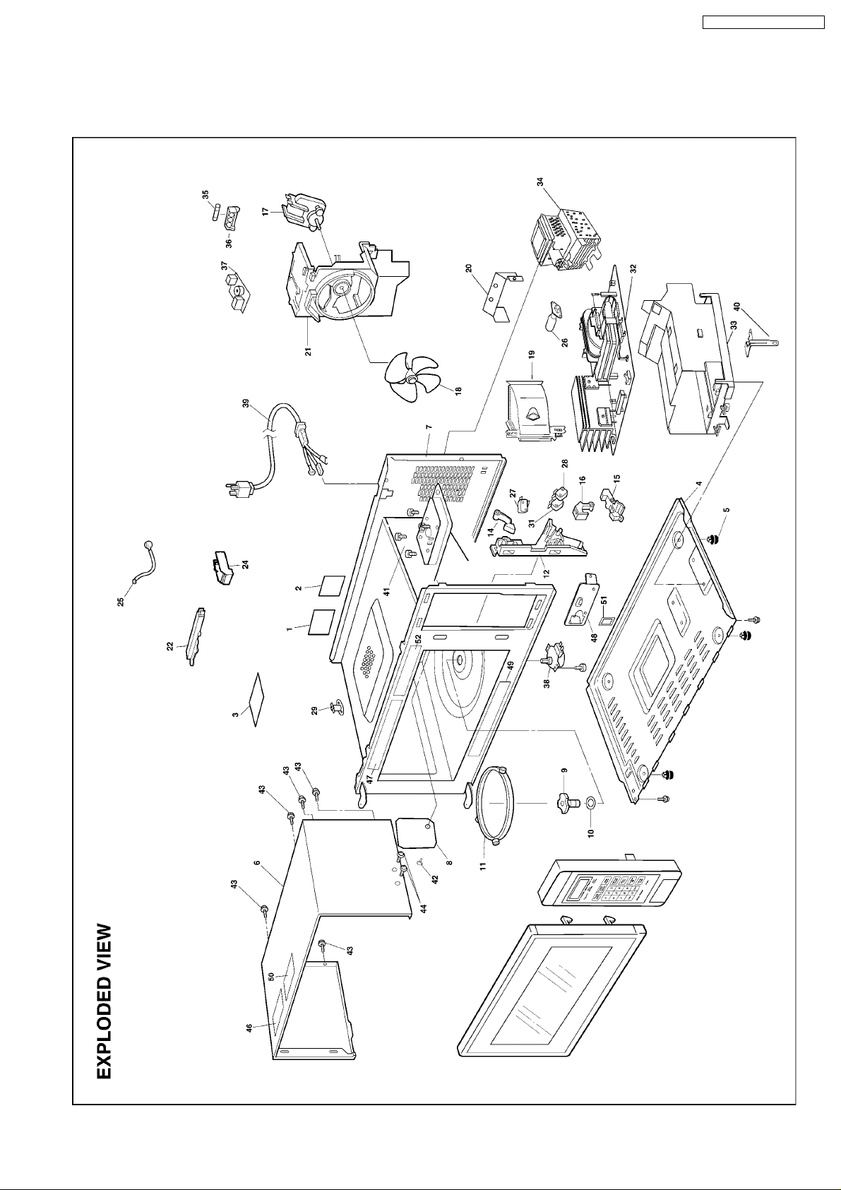
5 EXPLODED VIEW AND PARTS LIST
5.1. EXPLODED VIEW
NN-P994SFR / NN-P994BFR
11
NN-P994SFR / NN-P994BFR
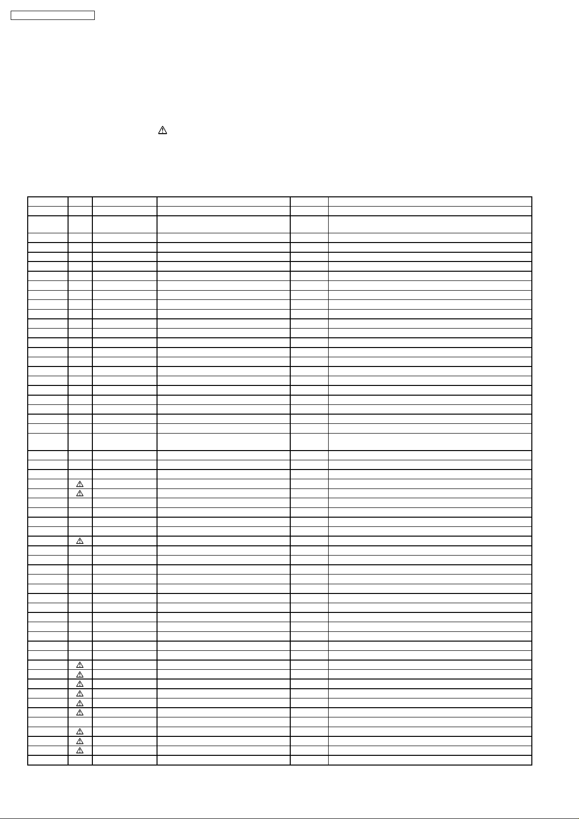
5.2. PARTS LIST
NOTE:
1. When ordering replacement part(s), please use part number(s) shown in this part list.
Do not use description of the part.
2. Important safety notice:
Components identified by
When replacing any of these components, use only manufacture’s specified parts.
NOTE:
“A” parts are supplied by CSD (Japan)
“F” parts are supplied by PHAMOS (China)
Ref. No. Part No. Part Name & Description Pcs/Set Remarks
1 F00064W70AP CAUTION LABEL 1 P994*FR APH,T9*5SF APH,T9*4SFR APH
1 F00069660AP CAUTION LABEL 1 H9*5 APH,S9*5 APH,S9*4BFR/WFR APH,
1 F00067600CP CAUTION LABEL 1 CPH
2 F00077B00BAP NAME PLATE 1 H965BF APH
2 F00077B00HAP NAME PLATE 1 H965WF APH
2 F00077E30BAP NAME PLATE 1 H935BF APH
2 F00077E30HAP NAME PLATE 1 H935WF APH
2 F00077B20BAP NAME PLATE 1 S955BF APH
2 F00077B20HAP NAME PLATE 1 S955WF APH
2 F00077B40BAP NAME PLATE 1 S935BF APH
2 F00077B40HAP NAME PLATE 1 S935WF APH
2 F00077B10BAP NAME PLATE 1 S954BFR APH
2 F00077B10HAP NAME PLATE 1 S954WFR APH
2 F00077E40BAP NAME PLATE 1 S934BFR APH
2 F00077E40HAP NAME PLATE 1 S934WFR APH
2 F00077B30HRP NAME PLATE 1 S955WF RPH
3 F00337D00AP FUSE LABEL 1 APH,CPH
3 F00337D00RP FUSE LABEL 1 RPH
4 F10016G10AP BASE 1
5 F10084T00AP RUBBER FOOT 4
6 F110D6G10SAP CABINET BODY 1 P994SFR
6 F110D6G20BAP CABINET BODY 1 P994BFR
6 F110D6G20HAP CABINET BODY 1 P994WFR
6 F110D5W10SAP CABINET BODY 1 T995SF APH/CPH,T995SF/SM RPH,
6 F110D4U50SAP CABINET BODY 1 T985SF APH,T955SF APH,T945SF APH,T935SF APH
6 F110D5W20BAP CABINET BODY 1 H9*5BF,S9*5BF,S9*4BFR
6 F110D5W20HAP CABINET BODY 1 H9*5WF,S9*5WF,S9*4WFR
7 F200A5W20AP OVEN 1 P994*FR,T9*5SF/SM,T9*4SFR APH,H9*5
7 F200A5W30AP OVEN 1 S9*5,S9*4BFR/WFR
8 F20555K00AP COVER 1
9 F21315Y00AP PULLY SHAFT 1
10 F2177-F80 WASHER 1
11 F290D9330AP ROLLER RING (U) 1
12 F3020-1200 DOOR HOOK 1
14 F3136-1200 HOOK LEVER A 1
15 F31374650AP HOOK LEVER B 1
16 F31384650AP HOOK LEVER C 1
17 F400A5Y00AP FAN MOTOR 1 AC120V,SINGLE PHASE,60Hz
18 F40084T00AP FAN BLADE 1
19 F40254W00AP AIR GUIDE A 1
20 F40264T60AP AIR GUIDE B 1
21 F41445W00AP ORIFICE 1
22 F64508660AP SENSOR COVER B 1 P994*FR,T9*5SF/SM,T9*4SFR APH,H9*5
24 F65434W00AP SENSOR COVER C 1 P994*FR,T9*5SF/SM,T9*4SFR APH,H9*5
25 A607S4M00AP STEAM SENSOR 1 P994*FR,T9*5SF/SM,T9*4SFR APH,H9*5
26 F612E4W00AP INCANDESCENT LAMP (U) 1 125V,60Hz,20W
27 J61424T00AP MICRO SWITCH 1 (PRIMARY LATCH SWITCH)(V-15G-3C25)
28 J61414T00AP MICRO SWITCH 1 (SECONDARY LATCH SWITCH)(D3V-16G-3C25)
29 F61456N60AP THERMAL CUTOUT 1 150°C/-20°C
31 J61784T00AP MICRO SWITCH 1 (SHORT SWITCH)(D3V-1G-2C25)
32 F606Y6G00AP H.V.INVERTER (U) 1 APH,RPH
32 F606Y6G00CP H.V.INVERTER (U) 1 CPH
33 F65856K50AP INVERTER BRACKET 1
34 2M261-M32F MAGNETRON 1 APH,RPH
34 2M261-M32J MAGNETRON 1 CPH
35 F62307A00AP FUSE 1 20A
36 F62315G10XN FUSE HOLDER 1 RPH
mark have special characteristics important for safety.
T995SF/SM RPH,S955WF/WM RPH
T975SF APH,T965SF APH,T9*4SFR APH
12
NN-P994SFR / NN-P994BFR
Ref. No. Part No. Part Name & Description Pcs/Set Remarks
37 J692Y7D00AP NOISE FILTER 1 APH
37 J692Y4T00CPR NOISE FILTER 1 CPH
38 F63265G60AP TURNTABLE MOTOR 1
39 F900C4T60CP AC CORD W/PLUG 1 P994*FR APH,T9*5SF APH,T9*4SFR APH
39 F900C4T00AP AC CORD W/PLUG 1 H9*5 APH,S9*5 APH,S954*FR APH,S934*FR APH,
39 F900C4W10CP AC CORD W/PLUG 1 CPH
40 F66626G10AP GROUNDING PLATE 1
41 XTWFA4+12T SCREW 4 FOR MAGNETRON
42 F90804W00AP CANOE CLIP 1 FOR COVER
43 XTTANE4T12A0 SCREW 5 FOR CABINET BODY
44 XTTFA4+8BFZ SCREW 2 FOR CABINET BODY SIDE
44 XTTFA4+8BCR SCREW 2 FOR CABINET BODY SIDE
46 F02445Y00AP CAUTION LABEL 1 P994SFR,T995SF/SM,T975SF,T965SF,T9*4SFR APH
47 F03347B60AP MENU LABEL 1 T995SF APH,T985SF APH
47 F03347B60CP MENU LABEL 1 T995SF CPH
47 F03347B60RP MENU LABEL 1 T995SF/SM RPH
47 F03347D60AP MENU LABEL 1 H965BF/WF APH,H935BF/WF APH
47 F03347D60CP MENU LABEL 1 H965BF/WF CPH
47 F03346L20AP MENU LABEL 1 S935BF/WF APH
47 F03347G50RP MENU LABEL 1 S955WF/WM RPH
48 F82575W00AP DOOR OPENING BRACKET 1 P994*FR,T955SF,T994SFR APH,
48 F82574U00AP DOOR OPENING BRACKET 1 T995SF/SM,T985SF,T975SF,T965SF,T945SF,
49 F04467D00AP FUNCTION LABEL 1 T995SF APH,T985SF APH
49 F04467D00CP FUNCTION LABEL 1 T995SF CPH
49 F04467D00RP FUNCTION LABEL 1 T995SF/SM RPH
50 F00066G00RP CAUTION LABEL 1 T995SF/SM RPH
51 F11406G00AP LEVER STOPPER 1 P994*FR,H965 APH/CPH,H935 APH,S935 APH
52 F00167D00AP CAUTION LABEL 1 T995SF APH,T985SF APH
T995 RPH,S955 RPH
(P994BFR,H9*5BF,S9*5BF,S9*4BFR)
(P994SFR/WFR,T9*5SF/SM,T9*4SFR,H9*5WF,S9*5WF,
S9*4WFR)
H965 APH/CPH,H935 APH,S935 APH
T935SF,T964SFR APH,S954*FR APH,
S934*FR APH,S955 APH/RPH
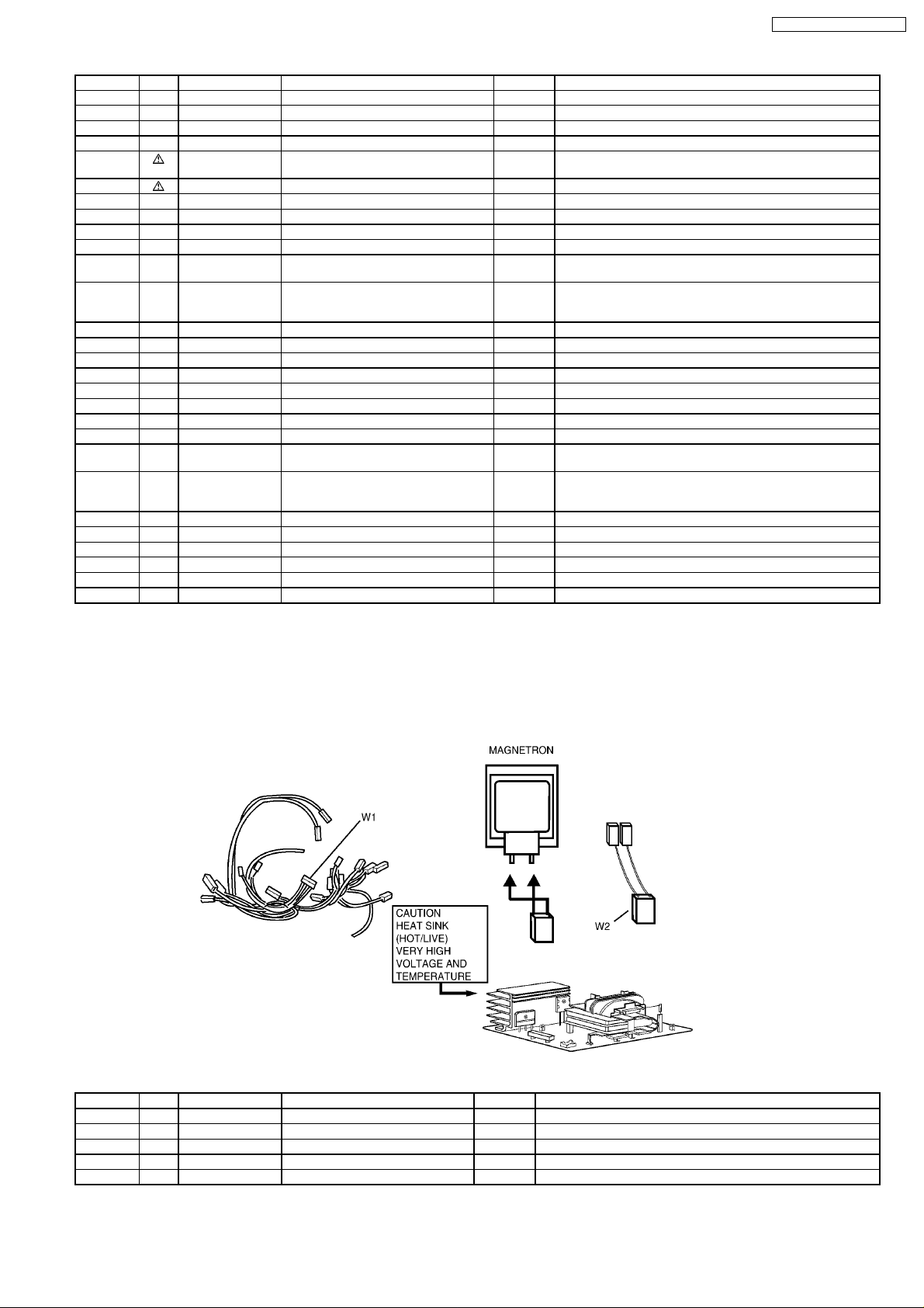
5.3. WIRING MATERIALS
Ref. No. Part No. Part Name & Description Pcs/Set Remarks
W1 F030A7B60AP LEAD WIRE HARNESS 1 APH
W1 F030A7B60CP LEAD WIRE HARNESS 1 CPH
W1 F030A6P40AG LEAD WIRE HARNESS 1 RPH
W2 F030E6G30AP H.V.LEAD WIRE 1 APH,RPH
W2 F030E6G30CP H.V.LEAD WIRE 1 CPH
13
 Loading...