

Panasonic NN-761, NN-S751 Schematic
& WARNING
This service information is designed for experienced repair technicians only and is not designed for use by the general publico It does not
contain warnings or cautions to advisenon-technical individuals of potential dangers in attempting to servicea produc!.
Productspowered by electricity should beservicedor repaired only by experiencedprofessionaltechnicians. Any attemptto service or repair
the productor productsdealt with in this service information by anyone elsecould result in serious injury or death.
WARNING
1.This product should be serviced only by trained, qualified personnel.
2.Check for radiation leakage before and after every servicing according to the "procedure for measuring radiation leakage."
3.lf the unit cannot be repaired on site, advise the customer not to use until unit is repaired.
4.There are special components used in the microwave oyen which are important for safety. These parts are marked with
a LL. on the replacement parts lis!. It is essential that these critical parts should be replaced only with the manufacture's
specified parts to preventmicrowave leakage, shock, tire, or other hazards. Do not modify the orginal designo
This service manual covers products for following markets.
When troubleshooting or replacing parts, please refer to the country identifications shown below for your
applicable product specification.
RPH For Mexico & LatinAmerican
PRECAUTIONS TO BE OBSERVED BEFORE AND
DURINGSERVICINGTOAVOIDPOSSIBLEEXPOSURE
TO EXCESSIVE MICROWAVEENERGY
(A) Do not operate or allow the oyen to be operated with the
door apeno
(B) Make the following safety checks on all ovens to be serviced
before activating the magnetron orother microwave source,
and make repairs as necessary:
(1) Interlock operation
(2) Proper door closing
(3) Seal and sealing surfaces (arcing, wear, and other
damage)
(4) Damage to or loosening of hinges and latches.
(5) Evidence of dropping or abuse
(C) Before turning on microwave power for any service test or
CONTENTS
(Page)
SCHEMATIC OIAGRAM 4
MEASUREMENTSANOADJUSTMENTS 5
PROCEDURE FOR MEASURING MICROWAVE ENERGY LEAKAGE 6
EXPLODEDVIEW AND PARTSLlST 7
SCHEMATIC OIAGRAM&
PARTSLlST OF DIGITAL PROGRAMMER CIRCUIT 12
inspection within the microwave generating compartments,
check the magnetron, waveguide or transmission line, and
cavity for proper alignment, integrity and connections.
(D) Any detective or misadjusted components in the interlock,
monitor, door seal, and microwave generation and trans-
mission systems shall be repaired, replaced, or adjusted
by procedures described in this manual before the oyen is
released to the owner.
(E) A microwave leakage check to verify compliance with the
Federal Performance Standard should be performed on
each oyen prior to release to the owner.
- 2-
DANGER OF HIGH VOLTAGE AND HIGHTEMPERATURE (HOT/LlVE) OFTHE INVERTER POWER SUPPLV (U)
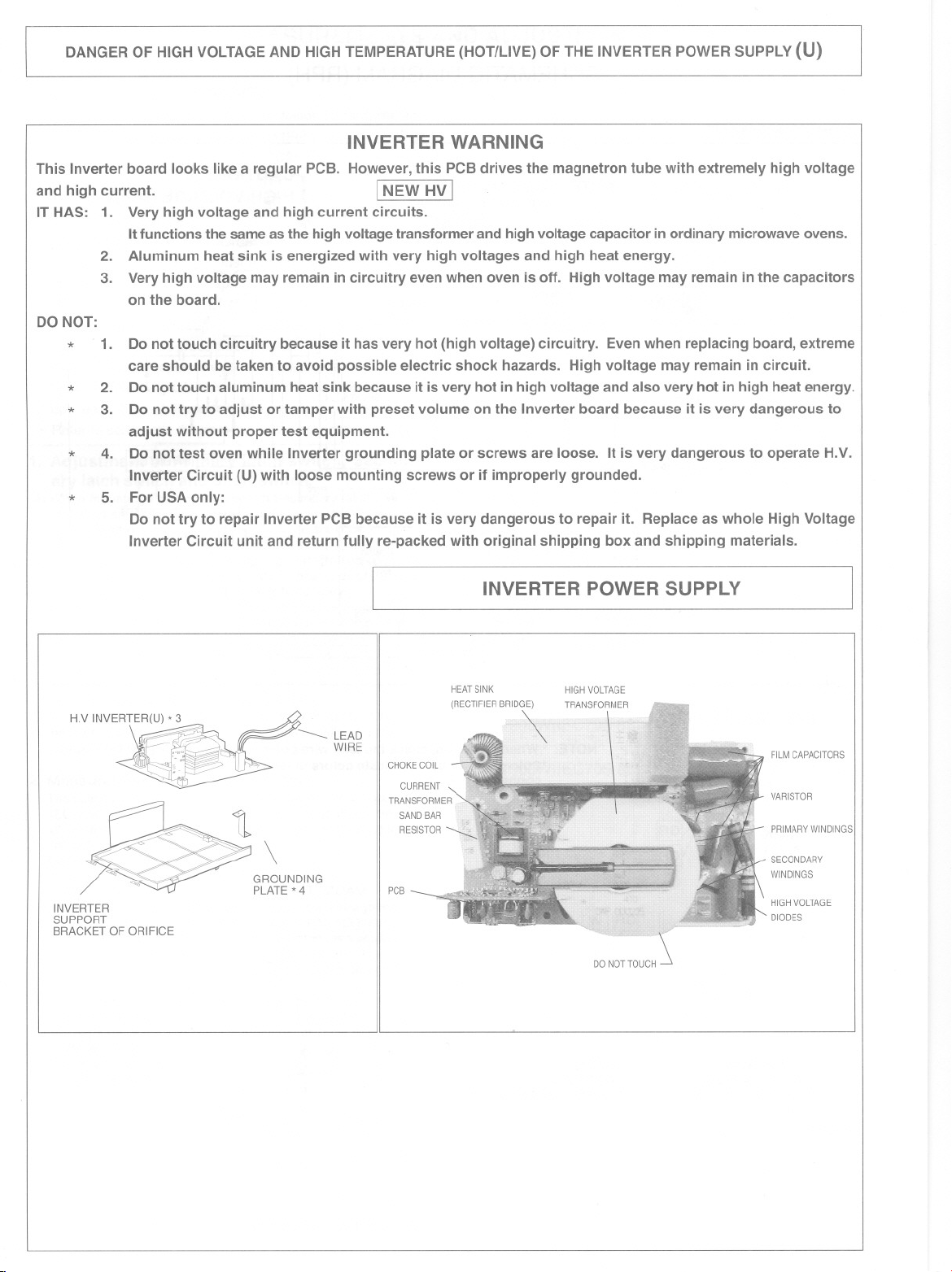
INVERTER WARNING
This Inverter board looks like a regular PCB. However, this PCB drives the magnetron tube with extremely high voltage
and high current.
IT HAS: 1. Very high voltage and high current circuits.
It functions the same as the high voltage transformer and high voltage capacitar in ordinary microwave ovens.
2. Aluminum heat sink is energized with very high voltages and high heat energy.
3. Very high voltage may remain in circuitry even when oven is off. High voltage may remain in the capacitors
on the board.
DO NOT:
* 1. Do not touch circuitry because it has very hot (high voltage) circuitry. Even when replacing board, extreme
care should be taken to avoid possible electric shock hazards. High voltage may remain in circuit.
*
2. Do not touch aluminum heat sink because it isvery hot in high voltage and also very hot in high heat energy.
*
3. Do not try to adjust or tamper with preset volume on the Inverter board because it is very dangerous to
adjust without proper test equipment.
*
4. Do not test oven while Inverter grounding plate or screws are loose. It is very dangerous to operate H.V.
Inverter Circuit (U) with loose mounting screws or if improperly grounded.
*
5. For USA only:
Do not try to repair Inverter PCB because it is very dangerous to repair it. Replace as whole High Voltage
Inverter Circuit unit and return fully re-packed with original shipping box and shipping materials.
INEW HV I
H.V INVE
RTER(U) * 3 ,- _-# LEAD
~
INVERTER
SUPPORT
BRACKET OF ORIFICE
. WIRE
,.,,-
'-..
\
GROUNDING
PLATE * 4
CHOKECOIL
PCB
INVERTER POWER SUPPLy
HEATSINK HIGHVOLTAGE
(RECTIFIERBRID\ TRANSFORMER
FILMCAPACITORS
VARISTOR
PRIMARYWINDINGS
SECONDARY
WINDINGS
HIGHVOLTAGE
DIODES
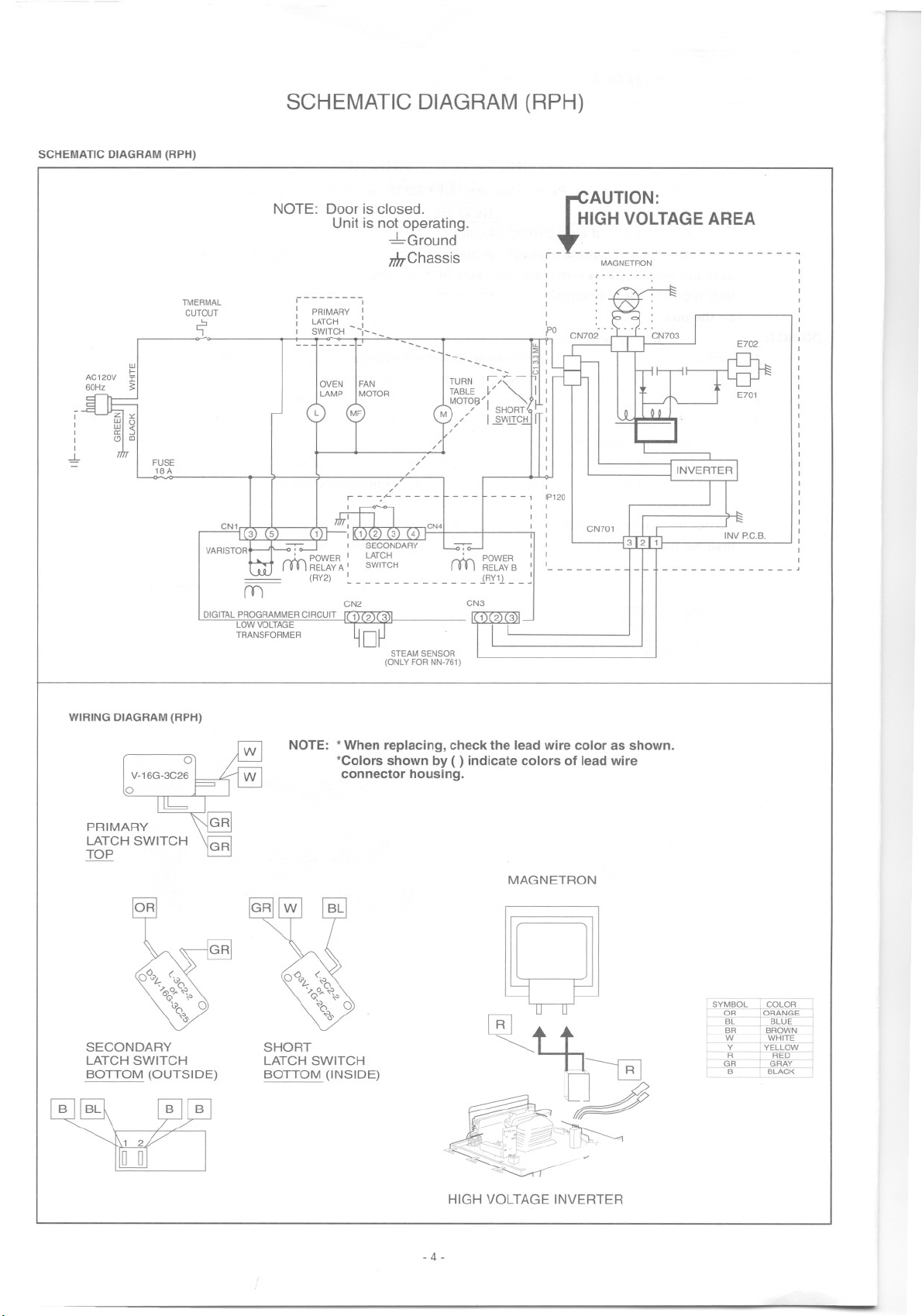
SCHEMATIC DIAGRAM (RPH)
SCHEMATIC DIAGRAM (RPH)
,
,
,
,
,
.J,.
AC120V I
60Hz ~
NOTE:
TMERMAL
CUTOUT
r;"
w
f-
FUSE
18A
CNI CN'
m
DIGITALPROGRAMMERCIRCUIT 1 2 (3"
LOWVOLTAGE
TRANSFORMER D
Dooris Glosad.
Unit is not operating.
, ,
I PRIMARY I
: LATCH -_:
, SW'TCH ,---
--~ ,-
OYEN
FAN
MOTOR
LAMP
r - - ~,<-- - - - -
CN2
-LGround
m,-Chassis
-----
-
M~/ 12WJI¿~IT:
/
/
STEAM SENSOR
(ONLY FOR NN-761)
TURN ,/ I
TABLE ~/ ~ I ,
MOT<;¡;¡/I SHORT :
CN3
~
-:
11
- - - -, P120
I I
I I
, ,
~AUTION :
- t~I~_~ ~-~~~~~-~ ~~~~ - - - --
,
MAGNETRON ,
,--------
'
I
I
,
,
,
CN701
,
,
,
,
--------
INV P.C.B.
,
,
1
,
,
I
I
,
,
,
,
,
,
,
,
,
,
,
,
I
,
,
,
,
,
I
I
,
,
,
,
,
WIRING DIAGRAM (RPH)
PRIMARY
LATCH SWITCH
TOP
SECONDARY
LATCH SWITCH
BOTTOM (OUTSIDE)
NOTE: *When replacing, check the lead wire color as shown.
*Colors shown by ( ) indicate colors of lead wire
connector housing.
MAGNETRON
SHORT
LATCH SWITCH
BOTTOM (INSIDE)
~I t+,.
~ ~-~
.
~.._~
'""~W"~
;-: v
~~ -
HIGH VOLTAGE INVERTER
- 4-
MEASUREMENTSANDADJUSTMENTS
WARNING
* For continued protection against radiation hazard, replace
onlywith identicalreplacementparts(Fortouch modelsPart
No.A6142-1450,TypeNo. V-16G-3C26-Mtor Primarylatch
switch Part No. A61425180AP,Type No. L-3C2-2 tor Sec-
ondary latch switch and Part No. A61785180AP,Type No.
L-2C2-2 tor short switch.)
* When the 15 Amp. tuse is blown due to the operation
ot the short switch, you must replaceprimary latchswitch
and short switch. Also replace power relay B (PartNo.
AEG5J1EG12B/AEG5J1EG18B,Type No. G5J-1-TP)when
the continuity check reads shortedcontacts (1-2).Then tol-
lowthe adjustment procedures below.
* Interlockswitch replacement-In replacingtaulty switches,
be sure mounting tabs are not bent, broken or otherwise
deticent in their ability to hold the switches.
* Reterto schematic diagramto ensure proper connection.
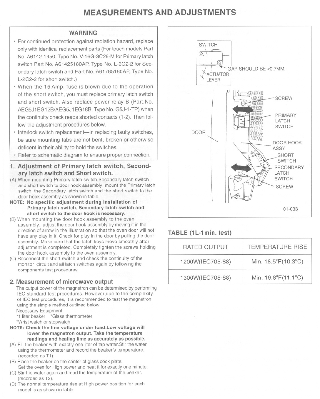
1. Adjustment of Primary latch switch, Second-
ary latch switch and Short switch.
(A) When mounting Primary latch switch,Secondary latch switch
and short switch to door hook assembly, mount the Primary latch
switch, the Secondary latch switch and the short switch to the
door hook assembly as shown in table.
NOTE: No specific adjustment during installation of
(B) When mounting the door hook assembly to the oven
(C) Reconnect the short switch and check the continuity 01the
2. Measurement of microwave output
NOTE: Check the line voltage under 10ad.Low voltage will
(A) Fill the beaker with exactly one liter 01tap water.Stir the water
(B) Place the beaker on the center 01glass cook plate.
(C) Stir the water again and read the temperature 01the beaker.
(D) The normaltemperature rise at High power position lor each
Primary latch switch, Secondary latch switch and
short switch to the door hook is necessary.
assembly, adjust the door hook assembly by moving it in the
direction 01arrow in the illustration so that the oven door will not
have any play in ít. Check lor play in the door by pulling the door
assembly. Make sure that the latch keys move smoothly after
adjustment is completed. Completely tighten the screws holding
the door hook assembly to the oven assembly.
monitor circuit and alllatch switches again by lollowing the
components test procedures.
The output power 01the magnetroncan be determinedby pertorming
lEC standard test procedures. However,due to the complexity
01lECtest procedures, it is recommended to test the magnetron
usingthe simple method outlined below.
Necessary Equipment:
*1 liter beaker *Glass thermometer
*Wrist watch or stopwatch
lower the magnetron output. Take the temperature
readings and heating time as accurately as possible.
usingthe thermometer and record the beaker's temperature.
(recorded as T1).
Set the oven lor High power and heat it lor exactly one minute.
(recorded as T2).
model is as shown in table.
SWITCH
Q
ACTUATOR
LEVER
DOOR
GAP SHOULD BE <0.7MM.
DOOR HOOK
ASSY
~ SHORT
\( SECONDARY
'~:k-~ r SWITCH
TABLE (1L-1mino test)
RATEO OUTPUT TEMPERATURE RISE
1200W(IEC705-88) Min. 18.5°F(1 O.3°C)
1300W(IEC705-88) Min. 19.8°F(11.1 °c)
PRIMARY
LATCH
SWITCH
LATCH
SWITCH
SCREW
01-033
PROCEDURE FOR MEASURING MICROWAVEENERGY LEAKAGE
WARNING
Gheck for radiation leakage after every servicing. Should
the leakage be more than 2 mW/cm2 (1mW/cm2 for
Ganada) inform PASe, PSG, or PGI immediately.
After repairing or replacing any radiation safety device,
keep a written record for future reference, as
required by D.H.H.S.and Health and Welfare Ganada
regulation.This requirement must be strictly observed.
In addition, the leakage reading must be recorded on
the service repair ticket while in the customer's home.
NOTE: The U.S. Government standard is 5 mW/cm2 while in
the customer's home. 2mW/cm2stated here is our own
voluntary standard. (1mW/cm2for Ganada)
1. Equipment
*Electromagnatic radiation monitor
*Glass thermometer 212 °F or 100DC
*600cc glass beaker
2. Procedure for measuring radiation leakage
Note before measuring.
(1) Do not exeeed meter full seale defleetion. Leakage monitor
should initially be set to the highest seale.
(2) Toprevent falsa readings the test proba should be held by the
grip portion of the handle only and moved along the shaded area
in Figure no tastar than 1 ineh/see(2.5em/see).
(3) Leakage with the outer panel removed less than 5mW/eni .
(4) Leakage for a fully assembled oven with door normally elosed
less than 2mW/cm2(1mW/em 2forGanada).
(5) Leakage for a fully assembled oven [Before the lateh switch
(primary) is interrupted} while pulling the door less than
2mW/em2.
(A)Pour275ct 15cc (90zs' ct1/20z) of 20° ct5 °C (68°ct9 °F) water in a
beaker which is graduated to 600cc, and place in the center of the
oyen.
(B) Set the radiation monitor to 2450MHz and use it following the
manufacturer's recommended test procedure to assure correct
results.
(C) When measuring the leakage, always use the 2 inch (5cm) spacer
supplied with the probe.
(O)Tapthe start pad or set the timer and with the magnetron oscillating,
measure the leakage by holding the probe perpendicular to the
surface being measured.
(1) Measurement with the outer panel removed.
Whenever you replacethe magnetron, measure for radiationleakage
beforethe outerpanel is installedand alter all necessarycomponents
are replaced or adjusted. Special Gafe should be taken in measur
ing around the magnetron.
WARNING
Avoid contacting any high voltage parts.
(2) Measurements with a fully assembled oven.
Alter all components, including outer panel are fully assembled,
measure for radiation leakage around the door periphery, the
door viewing window, the exhaust opening and air inlet openings.
(B) Should the radiation leakage be more than 2 mW/cm2(1mW/cm
for Ganada) alter determining that all parts are in good
condition, functioning properly, and genuine replacement
parts as listed in this manual have been used, immediately
notify PASC,PSC or PC!.
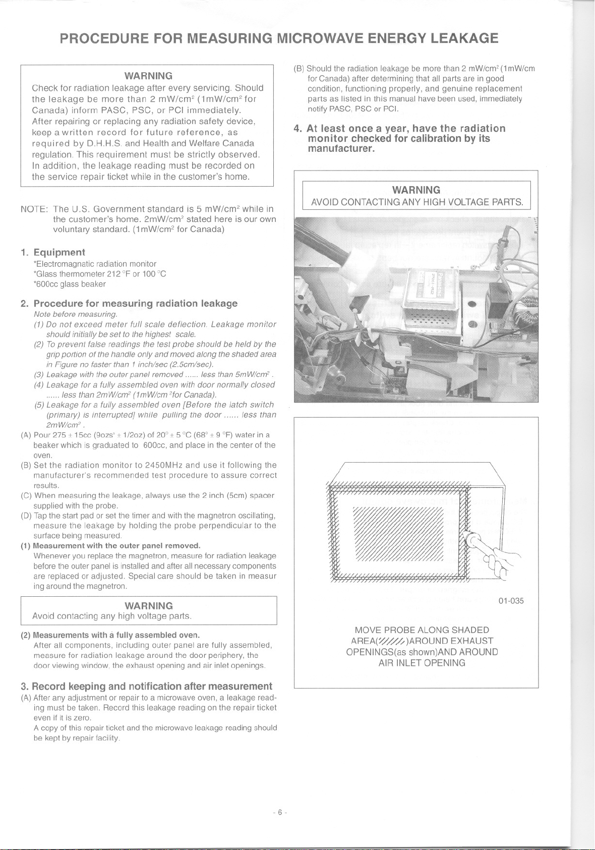
4. At least once ayear, have the radiation
monitor checked for calibration by its
manufacturero
WARNING
AVOIDGONTAGTINGANYHIGHVOLTAGEPARTS.
.
01-035
MOVE PROBE ALONG SHADED
AREA(~//fi )AROUND EXHAUST
OPENINGS(as shown)AND AROUND
AIR INLET OPENING
3. Record keeping and notification after measurement
(A)Alter any adjustment or repair to a microwave oyen, a leakage read-
ing must be taken. Record this leakage reading on the repair ticket
even if it is zero.
A copy of this repairticket and the microwaveleakage reading should
be kept by repair facility.
-6-
 Loading...