

Panasonic Nn-s723bl, Nn-s723wl, Nn-s732wl, Nn-s732bl Service Manual
Microwave Oven
NN-S723WL
NN-S723BL
Specifications
ITEM
Power Source
Power Requirement: Microwave
Output: Microwave
Microwave Frequency:
Timer:
Outside Dimensions:
Oven Cavity Dimensions:
Weight:
Specifications subject to change without notice.
ORDER NO. MOD0301268C1
E1
2003 Matsushita Electric Industrial Co., Ltd. All
rights reserved. Unauthorized copying and distribution
is a violation of law.
APH
120 V AC, 60 Hz
13.8 Amps, 1650W
1200 W: Full Power (IEC 60705)
2,450 MHz
30 MIN (HIGH) / 99 min. 99 sec.
13
17
/
32
”(H) x 22
19
/
32
”(W) x 17
5
/
16
”(D)
344mm(H) x 573.5mm(W) x 440mm(D)
109/32”(H) x 169/16”(W) x 1611/16”(D)
261mm(H) x 421mm(W) x 424mm(D)
Approx. 37.2 lbs (16.9 kg)
SAFETY PRECAUTIONS
PRECAUTIONS TO BE OBSERVED BEFORE AND
DURING SERVICING TO AVOID POSSIBLE
EXPOSURE TO EXCESSIVE MICROWAVE ENERGY
A) Do not operate or allow the oven to be operated with the door open.
B) Make the following safety checks on all ovens to be serviced before activating the magnetron or other
microwave source, and make repairs as necessary; (1) interlock operation, (2) proper door closing,
(3) seal and sealing surfaces (arcing, wear, and other damage), (4) damage to or loosening of hinges
and latches, (5) evidence of dropping or abuse.
C) Before turning on microwave power for any service test or inspection within the microwave generating
compartments, check the magnetron, wave guide or transmission line, and cavity for proper
alignment, integrity, and connections.
D) Any defective or misadjusted components in the interlock, monitor, door seal, and microwave
generation and transmission systems shall be repaired, replaced, or adjusted by procedures
described in this manual before the oven is released to the owner.
E) A microwave leakage check to verify compliance with the Federal Performance Standard should be
performed on each oven prior to release to the owner.
This service information is designed for experienced repair technicians only and is not designed for use by the
general public. It does not contain warnings or cautions to advise non-technical individuals of potential dangers in
attempting to service a product. Products powered by electricity should be serviced or repaired only by experienced
professional technicians. Any attempt to service or repair the product or products dealt with in this service information
by anyone else could result in serious injury or death.
1. This product should be serviced only by trained, qualified personnel.
2. Thought this product has been manufactured in compliance with:
“Federal Performance Standard 21 CFR Subchapter J” (D.H.H.S): U.S.A. models or
“Radiation Emitting Devices Act” (Health and Welfare Canada): Canadian models
It is very important all repairs should be made in accordance with procedures described in this manual to avoid
being exposed to excessive microwave radiation.
3. Check for radiation leakage before and after very servicing according to the “procedure for measuring radiation
leakage.”
4. If the unit cannot be repaired on site, advise the customer not to use until unit is repaired.
5. Any serviceman who learns of any accident pertaining to microwave radiation leakage including the oven operation
with open door should immediately notify the appropriate address listed below and Center for Devices and
Radiological Health, DHHS.
IN U.S.A. Panasonic Services Company IN PUERTO RICO PSC
(PASC) 50 Meadowland Parkway, (PSC) San Gabriel Industrial Park
Secaucus, New Jersey 07094 65th Infantry Ave. Km.9.5
Attention: Technical Service Division. Carolina, Puerto Rico 00985
(201)348-7000 (787)750-4300
6. There are special components used in the microwave oven which are important for safety. These parts are marked
with a on the replacement parts list. It is essential that these critical parts should be replaced only with the
manufacture’s specified parts to prevent microwave leakage, shock, fire, or other hazard. DO not modify the
original design.

(Page)
SAFETY PRECAUTIONS
---------------------------------------------------------------------
Inside front cover
POWER LEVEL & ACCESSORIES
-----------------------------------------------------------------------------
1-1
CAUTIONS
--------------------------------------------------------------------------------------------------------------
2-1
INSTALLATIONS
------------------------------------------------------------------------------------------------------
3-1
OPERATING INSTRUCTIONS
------------------------------------------------------------------------------------
4-1
FEATURES
------------------------------------------------------------------------------------------------------------------------
4-1
CONTROL PANEL
-------------------------------------------------------------------------------------------------------------
4-1
OPERATING SEQUENCE
----------------------------------------------------------------------------------------------------
4-2
SCHEMATIC DIAGRAM
------------------------------------------------------------------------------------------------------
4-3
CIRCUIT DESCRIPTION
-----------------------------------------------------------------------------------------------------
4-4
SERVICE INFORMATION
------------------------------------------------------------------------------------------
5-1
TOOLS AND MEASURING INSTRUMENTS
---------------------------------------------------------------------------
5-1
MICROWAVE LEAKAGE TEST
--------------------------------------------------------------------------------------------
5-1
MEASUREMENT OF MICROWAVE POWER OUTPUT
-----------------------------------------------------------
5-3
DISASSEMBLY AND ADJUSTMENT
-------------------------------------------------------------------------------------
5-3
INTERLOCK CONTINUITY TEST
------------------------------------------------------------------------------------------
5-7
COMPONENT TEST PROCEDURE
--------------------------------------------------------------------------------------
5-8
TROUBLE SHOOTING
------------------------------------------------------------------------------------------------------
5-11
CONTENTS
1-1
This microwave oven is designed for household use only.
It is not recommended for commercial purposes.
ITEM
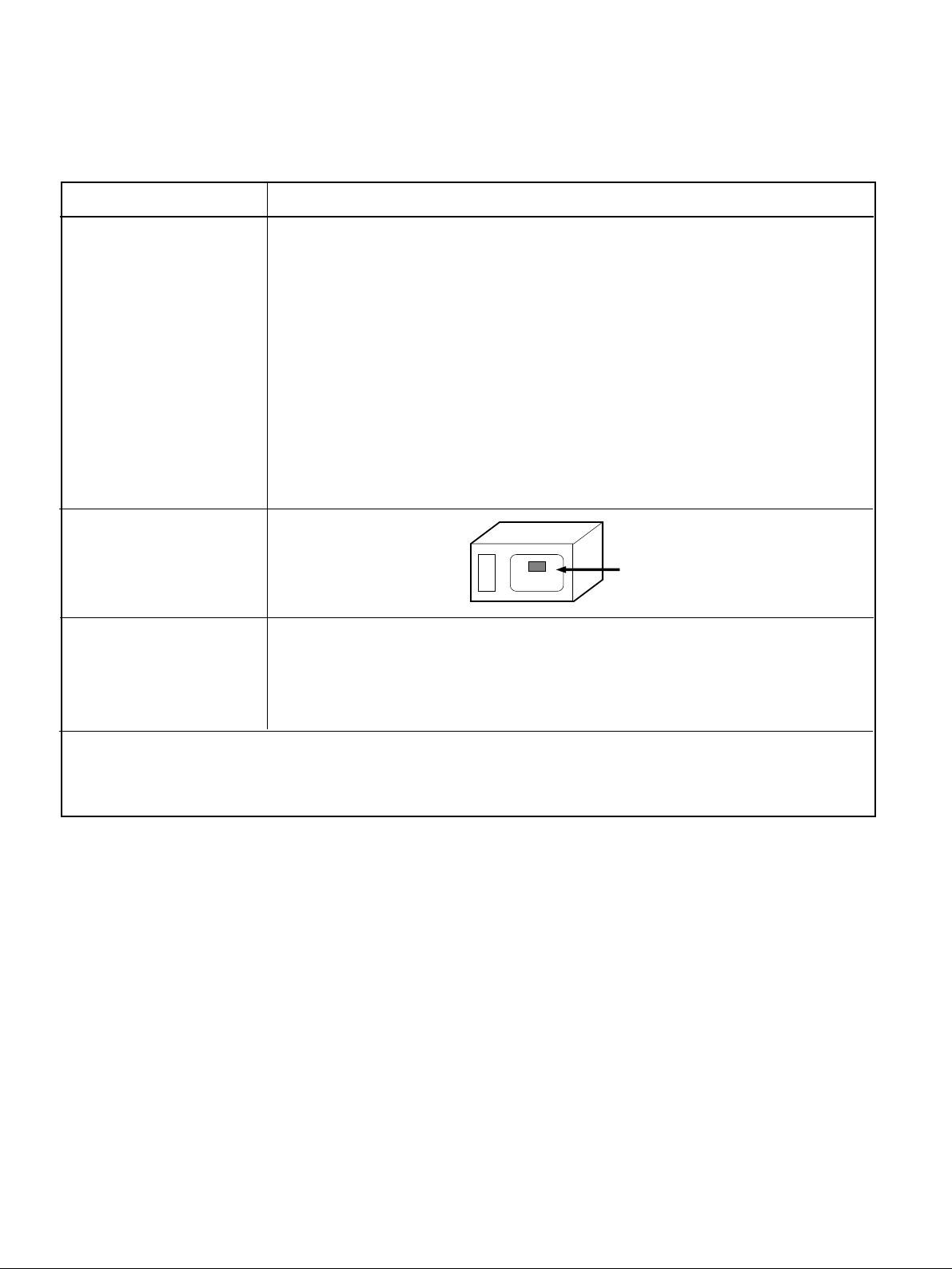
Control Complement
Nameplate Location
Accessories
DESCRIPTION
Touch Control System
Clock : 1:00 - 12:59
Microwave Power for Variable Cooking
Power level
HIGH ----------------------------------------Full power throughout the cooking time
9 (Saute) -------------------------approx. 90% of Full power, 8 (Reheat) --------approx. 80%
7 (Med.-High)--------------------approx. 70%, 6 (Medium) --------approx. 60%
5 (Med.-Low) --------------------approx. 50%, 4 (Defrost) ---------approx. 40%
3 (Low) ---------------------------approx. 30%, 2 (Simmer)--------approx. 20%
1 (Warm)--------------------------approx. 10%
Owner's manual
Glass turntable
Rotating ring
Back Side
POWER LEVEL & ACCESSORIES
• DO NOT operate on a 2-wire extension cord during
repair and use.
• NEVER TOUCH any oven components or wiring during
operation.
• BEFORE TOUCHING any parts of the oven, always
remove the power plug from the outlet.
• For about 30 seconds after the oven stops, an electric
charge remains in the high voltage capacitor. When
replacing or checking, you must discharge the high
voltage capacitor by shorting across the two terminals
with an insulated screwdriver.
•
Remove your watches whenever working close to or
replacing the Magnetron.
• DO NOT touch any parts of the control panel circuit. A
resulting static electric discharge may damage this
P.C.B.
• NEVER operate the oven with no load.
• NEVER injure the door seal and front plate of the oven
cavity.
• NEVER put iron tools on the magnetron.
• NEVER put anything into the latch hole and the
interlock switches area.
• Proper operation of the microwave oven requires that
the magnetron be assembled to the waveguide and
cavity. Never operate the magnetron unless it is
properly installed.
• Be sure that the magnetron gasket is properly
installed around the dome of the tube whenever
installing the magnetron.
2-1
CAUTIONS
Unlike other appliances, the microwave oven is
high-voltage and high-current equipment.
Though it is free from danger in ordinary use,
extreme care should be taken during repair.
THE OVEN IS TO BE SERVICED ONLY
BY PROPERLY QUALIFIED SERVICE
PERSONNEL.
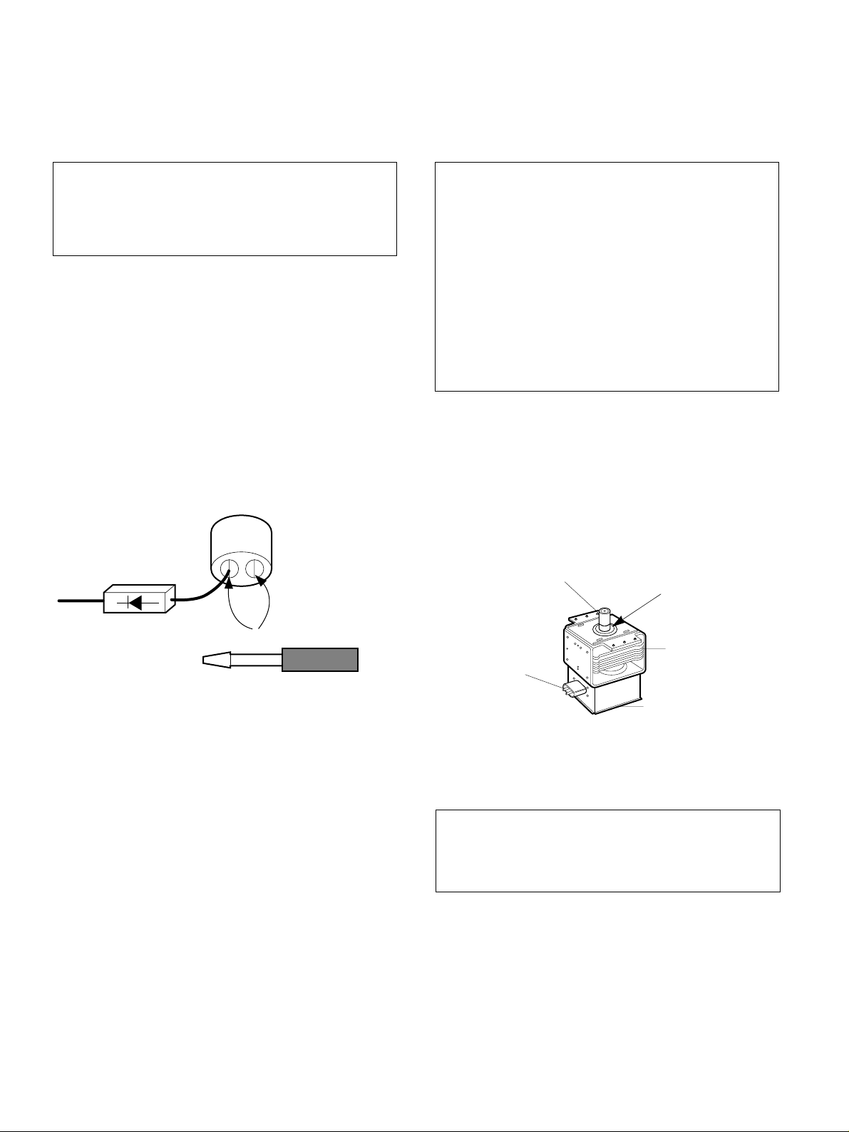
MICROWAVE RADIATION
Personnel should not be exposed to the
microwave energy which may radiate from the
magnetron or other microwave generating
device if it is improperly used or connection.
All input and output microwave connections,
waveguide, flange, and gasket must be secure
never operate the device without a microwave
energy absorbing load attached.
Never look into an open waveguide or antenna
while the device is energized.
Gasket
ANTENNA
COOLING FIN
MAGNETRON
CHASSIS GROUND
FILAMENT
TERMINALS
MAGNETRON
INSTALLATIONS
3-1
INSTALLING
1. Empty the microwave oven and clean inside it with
a soft, damp cloth. Check for damage such as
misaligned door, damage around the door or dents
inside the cavity or on the exterior.
2. Put the oven on a counter, table, or shelf that is
strong enough to hold the oven and the food and
utensils you put in it. (The control panel side of the
oven is the heavy side. Use care when handling.)
3. Do not block the vent and the air intake openings.
Blocking vent or air intake openings can cause
damage to the oven and poor cooking results.
Make sure the microwave oven legs are in place to
ensure proper air flow.
4. The oven should not be installed in any area where
heat and steam are generated, because they may
damage the electronic or mechanical parts of the
unit.
Do not install the oven next to a conventional
surface unit or above a conventional wall oven.
5. Use microwave oven in an ambient temperature
less than 104°F (40°C).
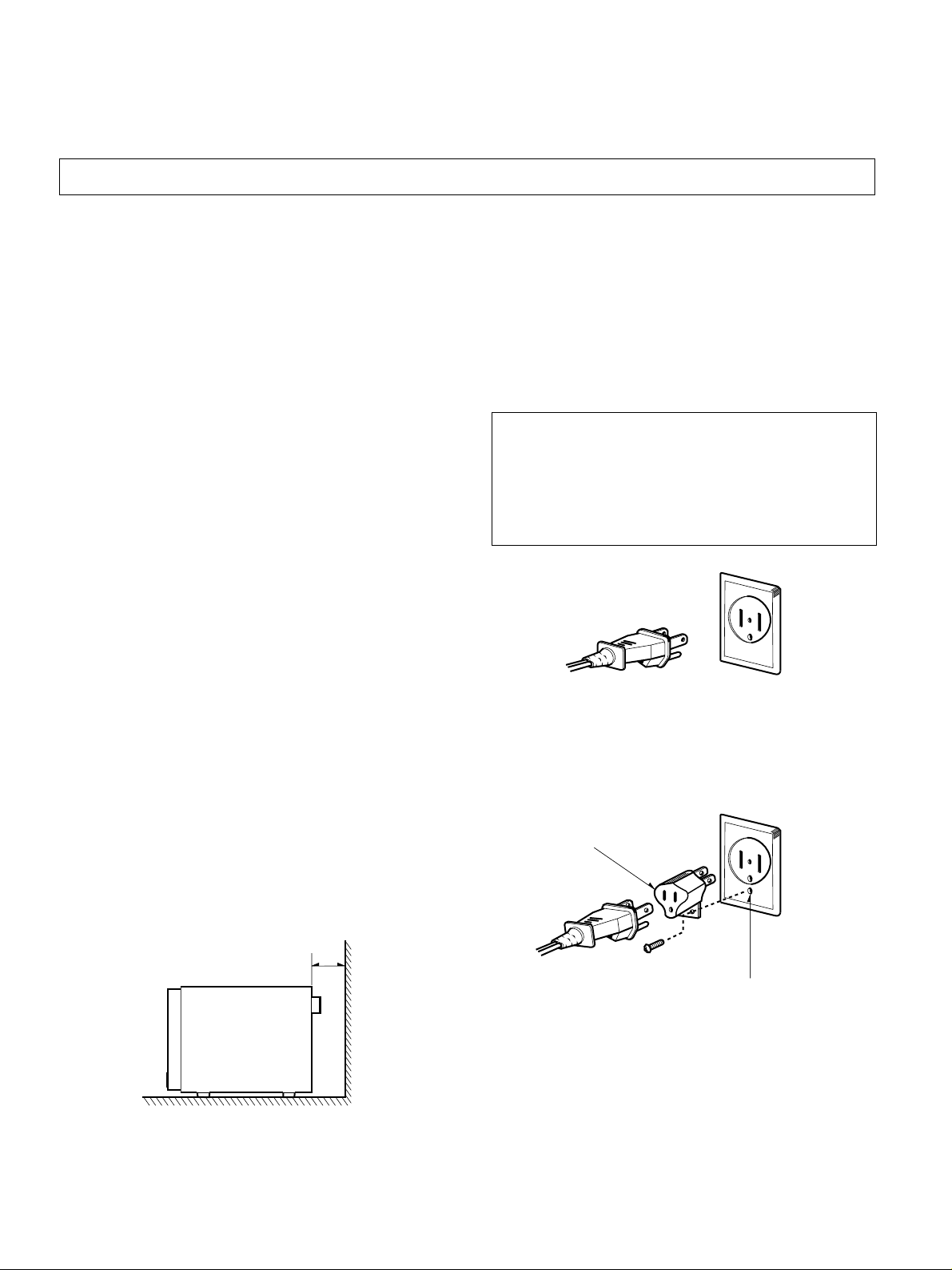
6. Place the microwave oven on a sturdy and flat
surface at least 10 cm (4 inches) from the wall.
7. Place the microwave oven as far away as possible
from TV, RADIO, COMPUTER, etc., to prevent
interference.
GROUNDING INSTRUCTIONS
For personal safety, this appliance must be fully
grounded at all times.
In the event of an electrical short circuit, grounding
reduces the risk of electrical shock.
The plug must be plugged into an outlet that is
properly installed and grounded.
BEFORE YOU BEGIN, READ THE FOLLOWING INSTRUCTIONS COMPLETELY AND CAREFULLY.
WARNING
Improper use of the grounding plug can result in a
risk of electric shock.
Do not, under any circumstances, cut or remove
the third ground prong from the power cord plug.
PREFERRED METHOD
ENSURE PROPER GROUND
EXISTS BEFORE USE
TEMPORARY METHOD
(ADAPTER PLUGS NOT
PERMITTED IN CANADA)
ALIGN LARGE
PRONGS/SLOTS
10cm
ENSURE PROPER GROUND
AND FIRM CONNECTION
BEFORE USE
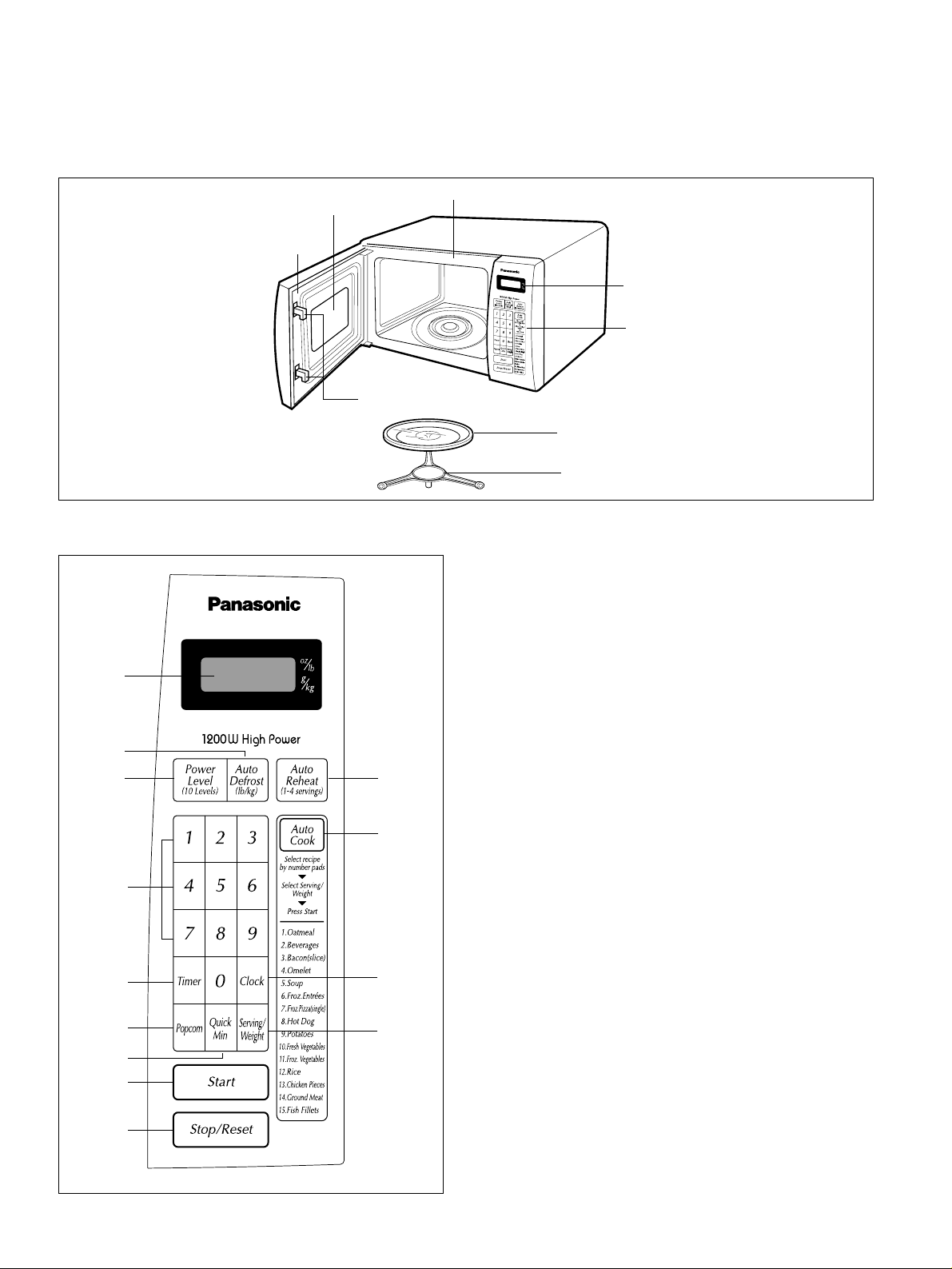
FEATURES
CONTROL PANEL
4-1
OPERATING INSTRUCTIONS
Oven Front Plate
Window Door Screen
Door Seal
Control Panel
Safety
Interlock
System
Turntable
Rotating Ring
Display Window
1. DISPLAY. The display includes a clock and
indicators that tell you time of day, cooking time settings,
and cooking functions selected.
2. AUTO DEFROST. Touch this pad to thaw meat, fish, or
poultry by entering a weight.
3. POWER LEVEL. Touch this pad to set a
cooking power.
4. AUTO REHEAT. This feature to reheat 1 to 4 servings of
precooked room temperature and refrigerator
temperature foods without setting power.
5. AUTO COOK. This function allows you to cook food
without entering a cook time or power.
6. NUMBER PADS. Touch number pads to enter cooking
time, power level, quantities, or weights.
7. TIMER. Touch this pad to use your microwave oven as a
kitchen timer.
8. POPCORN. Touch this pad to pop a bag of microwave
popcorn without entering a cook power or time.
9. QUICK MIN. Touch this pad to cook at 100% cook power
for 1 minute to 30 minutes.
10. CLOCK. Touch this pad to enter the time of day.
11. SERVING/WEIGHT.
12. START PAD. Touch this pad to start all entries
(except the auto cook and quick min function swhich start
automatically) and to turn Child Lock on or off.
13. STOP/RESET PAD. Touch this pad to stop the oven or
reset entries.
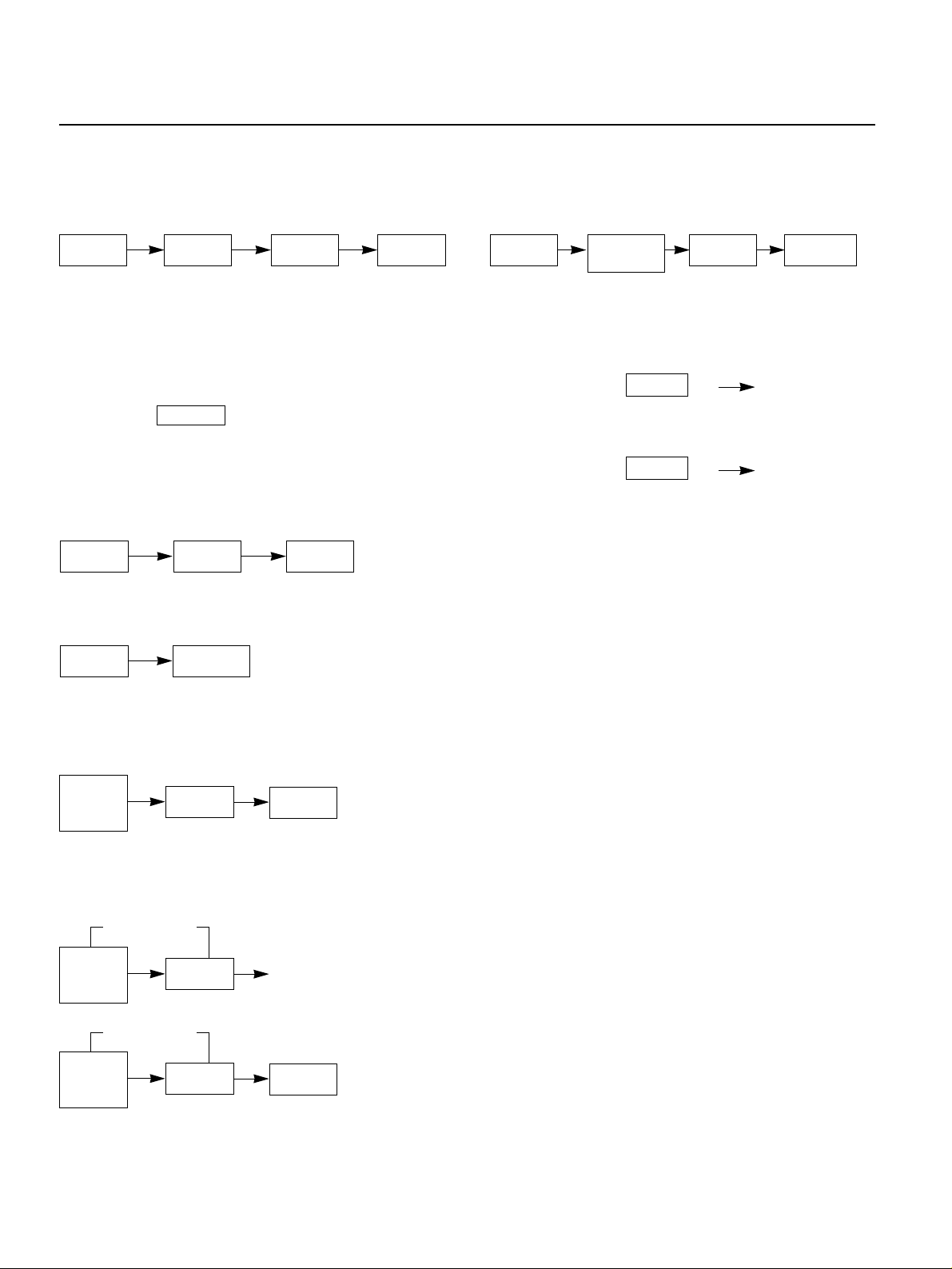
4-2
OPERATING SEQUENCE
The following is a description of component functions
during oven operation.
1. SETTING THE CLOCK
ex.) To set 4:30, touch number key [4],[3], and [0].
NOTE: 1) This is a 12 hour clock.
2) Clock will operate as long as power is
applied to the oven.
2. CANCEL FUNCTION
Touch the pad whenever you need to
cancel an entry or a function currently in use.
The display will return either to the last item entered
or to the clock.
3. QUICK MIN
4. AUTO COOKING
NOTE: Heat only 1 package at a time
5. TIME COOKING
6. MULTI-STAGE COOKING
7. AUTO DEFROST COOKING
8. CHILD LOCK
This oven has a CHILD LOCK feature
TO SET CHILD LOCK
• Touch and hold START pad L appears
on the display.
TO CANCEL CHILD LOCK
• Touch and hold START pad L disappears
on the display.
STOP/RESET
CLOCK NUMBER
STOP/RESET
POPCORN
STOP/RESET
QUICK MIN START
START
STOP/RESET
1ST STAGE
2ST STAGE
CLOCK
STOP/RESET
AUTO
DEFROST
WEIGHT
START
POWER
LEVEL
(10 LEVELS)
NUMBER
POWER
LEVEL
(10 LEVELS)
NUMBER
START
POWER
LEVEL
(10 LEVELS)
NUMBER
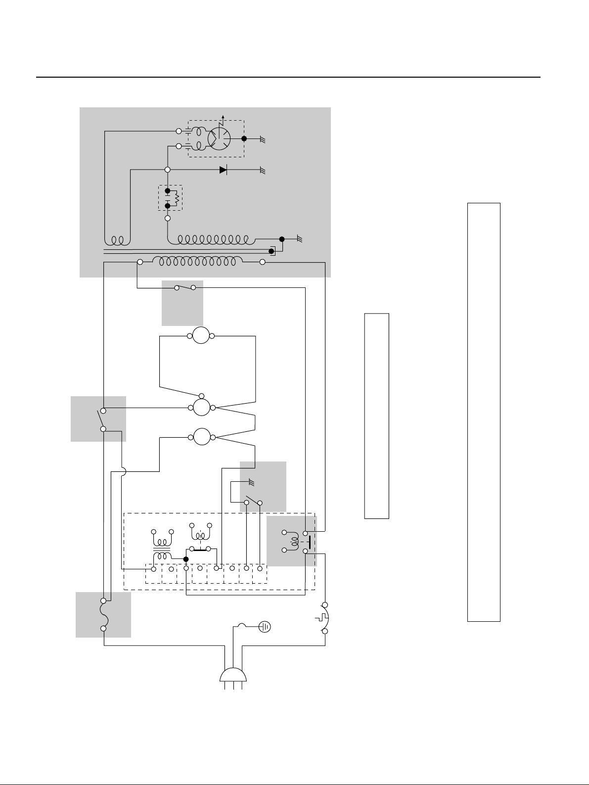
SCHEMATIC DIAGRAM
4-3
RD
RD
BK
PRIMARY
SWITCH
WH
WH
WH
WH
YL
MAGNETRON
RD
H.V.
CAPACITOR
H.V. DIODE
FUSE
20A
AC 120V
60Hz
BL
L
N
MICOM
CONTROLLER
F.M.
TRANSFORMER
H.V.
** NOTE : DOOR IS OPENED.
BK : BLACK BL : BLUE YL : YELLOW RD : RED
WH : WHITE PK : PINK GN : GREEN BN : BROWN
T.T.M.
O.L.
CN1
PT1
1
2
3
4
5
6
7
8
BK
BK
GN
GN
PK
BN
SECONDARY
SWITCH
OVEN
LAMP
MONITOR
SWITCH
TURN
TABLE
MOTOR
FAN
MO TOR
IMPORTANT SAFETY NOTE: THE SHADED AREAS ON THIS SCHEMATIC DIAGRAM INCORPORATE SPECIAL FEATURES
IMPORTANT FOR PROTECTION FROM MICROWAVE RADIATION, FIRE, ELECTRICAL SHOCK, AND
HAZARDS. WHEN SERVICING IT IS ESSENTIAL THAT ONLY MANUFACTURER'S SPECIFIED PARTS
BE USED FOR THE CRITICAL COMPONENTS IN THE SHADED AREAS OF THE SCHEMATIC DIAGRAM.
NOTICE: SINCE THIS IS BASIC SCHEMATIC DIAGRAM, THE VALUES OF COMPONENTS AND
SOME PARTIAL CONNECTIONS ARE SUBJECT TO CHANGE FOR IMPROVEMENT.
RY1
RY2
GN
WH
BK
CIRCUIT DESCRIPTION
GENERAL DETAILS
• The low voltage transformer supplies the necessary
voltage to the micom controller when power cord is
plugged in.
• When the door is closed, the primary switch is ON, the
secondary switch is ON, and the monitor switch opens
(contact COM and NO).
WHEN SELECTING COOKING POWER
LEVEL AND TIME
• The micom controller memorizes the function you set.
• The time you set appears in the display window.
• Each indicator light turns on to indicate that the stage
has been set.
WHEN TOUCHING THE START PAD
• The coil of the relay is energized by the micom
controller.
• Power input is supplied to the high voltage transformer
through the fuse to the primary switch and relay 2.
• Turntable rotates.
• The fan motor rotates and cools the magnetron by
blowing air (coming from the intake on the base-plate).
• The air is also directed into the oven to exhaust the
vapor in the oven through the upper plate.
• Cooking time starts counting down.
• 3.3 volts AC is generated from the filament winding of
the high voltage transformer. This 3.3 volts is applied to
the magnetron to heat the magnetron filament through
two noise-preventing choke coils.
• A high voltage of approximately 2100 volts AC is
generated in the secondary of the high voltage
transformer which is increased by the action of the high
voltage diode and charging of the high voltage
capacitor.
• The negative 4,000 Volts DC is applied to the filament
of the magnetron.
WHEN THE OVEN IS SET AT ANY LEVEL
EXCEPT MAXIMUM.
• The micom controller controls the ON-OFF time of
relay 2 by the applied signal to vary the average output
power of microwave oven as POWER LEVEL.
(refer to page 1-1)
• One complete cycle of the relay 2 is 22 seconds.
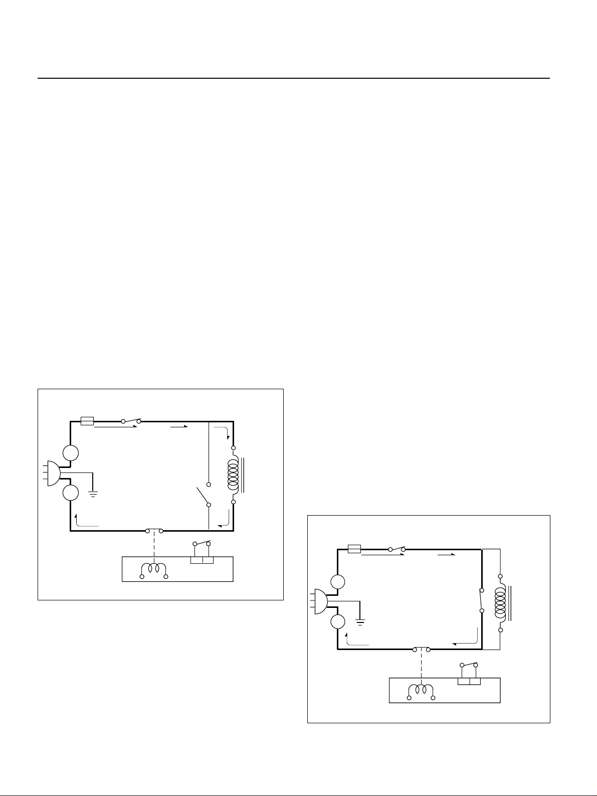
WHEN THE DOOR IS OPENED DURING
COOKING
• Both the primary switch and relay 2 cut off the primary
winding voltage of the high voltage transformer.
• ON-OFF of relay 2 is coupled electrically with opening
and closing of the secondary switch.
• When the door is opened, the secondary switch is
opened and when the door is closed, the secondary
switch is closed.
• The cooking time stops counting down.
• Relay stops functioning.
• As the door is opened, if the contact of primary switch
and relay 2 and/or secondary switch fail to open, the
fuse opens due to the large current surge caused by
the monitor switch activation, which, in turn, stops
magnetron oscillation.
4-4
L
FUSE
H.V.
TRANS-
FORMER
RELAY 2
MICOM CONTROLLER
SECONDARY
SWITCH
PRIMARY
SWITCH
MONITOR
SWITCH
N
PRIMARY
FUSE
L
N
SWITCH
MONITOR
SWITCH
RELAY 2
MICOM CONTROLLER
H.V.
TRANS-
FORMER
SECONDARY
SWITCH
CAUTIONS
• Be sure to check microwave leakage prior to
servicing the oven if the oven is operative prior to
servicing.
• The service personnel should inform the
manufacture importer, or assembler of any certified
oven unit found to have a microwave emission
level in excess of 5 mW/cm2and should repair any
unit found to have excessive emission levels at no cost
to the owner and should ascertain the cause of the
excessive leakage. The service personnel should
instruct the owner not to use the unit until the oven has
been brought into compliance.
• If the oven operates with the door open, the service
personnel should:
- Tell the user not to operate the oven.
- Contact the manufacturer and CDRH
(Center for Devices and Radiological Health)
immediately.
NOTE: Address on CDRH
Office of Compliance(HFZ-312)
Center for Devices and Radiological
Healthe 1390, Piccard Drive,
Rockville. MD 20850
• The service personnel should check all surface and
vent openings for microwave leakage.
• Check for microwave leakage after every servicing. The
power density of the microwave radiation leakage
emitted by the microwave oven should not exceed
4 mW/cm2. Always start measuring of an unknown field
to assure safety for operating personnel from radiation
leakage.
MEASURING MICROWAVE ENERGY
LEAKAGE
• Pour 275±15cc of 20±5°C (68±9°F) water in a beaker
which is graduated to 600 cc, and place the beaker
on the center of the turntable.
• Set the energy leakage monitor to 2,450 MHz and
use it following the manufacturer's recommended
test procedure to assure correct result.
• When measuring the leakage, always use the 2-inch
(5cm) spacer supplied with the probe.
• Operate the oven at its maximum output.
• Measure the microwave radiation using and
electromagnetic radiation monitor by holding the
probe perpendicular to the surface being measured
Move probe along shaded area
Probe scanning speed
Less than 2.5 cm/sec
(1 in/sec)
5-1
SERVICE INFORMATION
TOOLS AND MEASURING INSTRUMENTS
MICROWAVE LEAKAGE TEST
NECESSARY TOOLS
Tools normally used for TV servicing are sufficient.
Standard tools are listed below.
• Diagonal pliers
• Long nose pliers
• Phillips screwdriver
• Flat blade screwdriver
• Wrench (size 5mm)
• Nutdriver (size 5mm)
• Adjustable wrench
• Soldering iron
• Solder
• Vinyl insulation tape
• Polishing cloth
NECESSARY MEASURING INSTRUMENTS
• TESTER (VOLTS-DC, AC, Ohmmeter)
• Microwave survey meter
- Holaday HI-1500
HI-1501
- Narda 8100
8200
• Inch scale
• 600 cc non conductive material beaker (glass or plastic),
inside diameter: approx. 8.5 cm (3
1
/2
in.)
• Cylindrical and made of borosilicate glass vessel.
max. thickness: 3 mm
outside diameter: approx. 190mm
height: approx. 90mm
• Glass thermometer: 100°C or 212°F (1 deg scale)
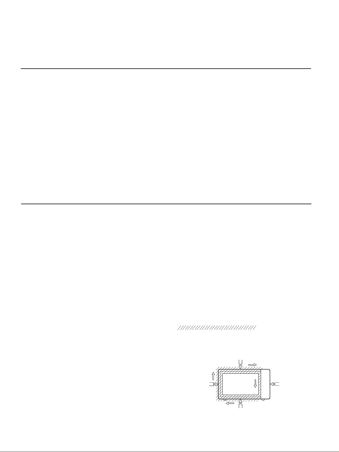
MEASUREMENT WITH OUTER CASE
REMOVED
• When you replace the magnetron, measure for
microwave energy leakage before the outer case is
installed and after all necessary components are
replaced or adjusted.
Special care should be taken in measuring the
following parts. (Circled area of Fig. below)
- Around the magnetron
- The waveguide
MEASUREMENT WITH A FULLY
ASSEMBLED OVEN
• After all components, including the outer case, are fully
assembled, measure for microwave energy leakage
around the door viewing window, the exhaust opening,
and air inlet openings.
• Microwave energy leakage must not exceed the values
prescribed below.
NOTE: Leakage with the outer case removed less than
5 mW/cm.sq. Leakage for a fully assembled
oven (Before the latch switch (primary) is
interrupted) with the door in a slightly opened
position-less than 2 mW/cm.sq.
NOTES WHEN MEASURING
• Do not exceed meter full scale deflection.
• The test probe must be removed no faster than
1 inch/sec (2.5 cm/sec) along the shaded area,
otherwise a false reading may result.
• The test probe must be held with the grip portion of the
handle.
A false reading may result if the operator's hand is
between the handle and the probe.
• When testing near a corner of the door, keep the probe
perpendicular to the surface making sure the probe
horizontally along the oven surface; this may cause
probe damage.
RECORD KEEPING AND NOTIFICATION
AFTER MEASUREMENT
• After adjustment and repair of any microwave energy
interruption or microwave energy blocking device,
record the measured values for future reference. Also
enter the information on the service invoice.
• The microwave energy leakage should not be more
than 4 mW/cm.sq. after determining that all parts are in
good condition, functioning properly and genuine
replacement parts which are listed in this manual have
been used.
• At least once a year, have the electromagnetic energy
leakage monitor checked for calibration by its
manufacturer.
5-2
WARNING : AVOID CONTACTING ANY
HIGH VOLTAGE PARTS
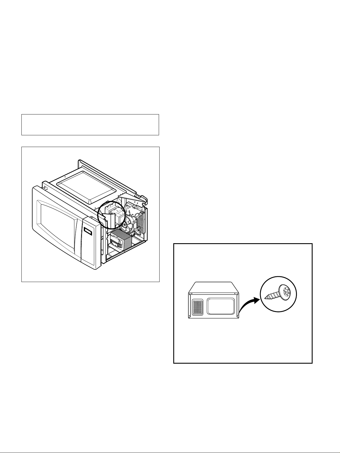
SPECIAL TIP
• This oven used the button head screws.
• When you remove the screws, use
the tamper-resistant Torx driver having a
pin-in-head.
Button Head
(Torx style 2)
 Loading...