

Page 1
NN-C2000P
NN-C2000W
MOD0009237C3
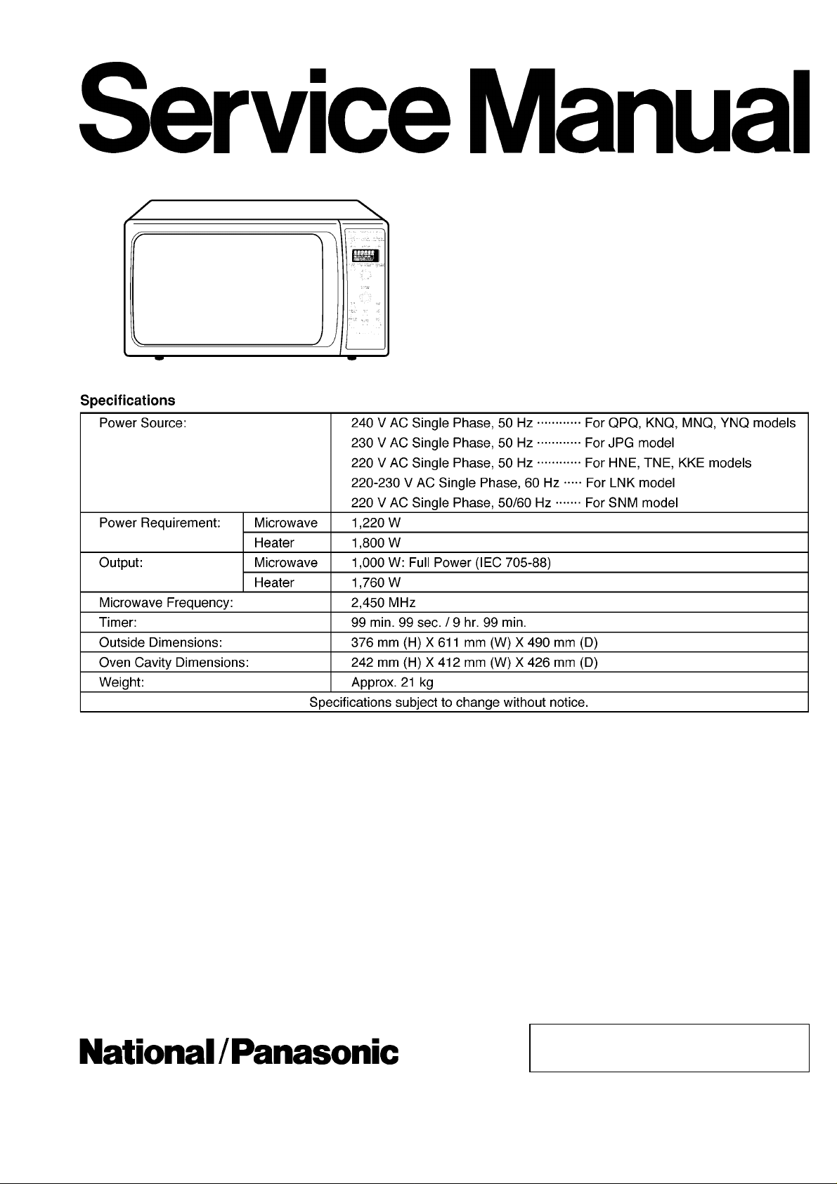
Microwave Oven
© 2000 Matsushita Electric Industrial Co., Ltd. All
rights reserved. Unauthorized copying and
distribution is a violation of law.
Page 2
NN-C2000P / NN-C2000W
CONTENTS
Page Page
1 FEATURE CHART 4
2 CONTROL PANEL
3 OPERATION AND DIGITAL PROGRAMMER CIRCUIT TEST
5
PROCEDURE
2
6
Page 3

4 SCHEMATIC DIAGRAM (FOR QPQ, JPG) 7
W
5 SCHEMATIC DIAGRAM (FOR MNQ, YNQ, TNE, LNK, SNM,
KNQ, KKE)
6 DESCRIPTION OF OPERATING SEQUENCE
7 CAUTIONS TO BE OBSERVED WHEN TROUBLESHOOTING
8 DISASSEMBLY AND PARTS REPLACEMENT PROCEDURE
9 COMPONENT TEST PROCEDURE
10 MEASURE MENTS AND ADJUSTMENTS
11 TROUBLE SHOOTING GUIDE (NEW H.V.)
12
14
18
21
22
12 HOW TO CHECK THE SEMICONDUCTORS USING AN OHM
METER
29
13 EXPLODED VIEW AND PARTS LIST
14 PARTS LIST
15 DOOR ASSEMBLY
8
9
16 ESCUTCH EON BASE ASSEMBLY
17 PACKING AND ACCESOR IES
18 WIRING MATERIAL
19 REF. NO. 47 H. V. INVERTER (U)
20 R EF NO . E2 P. C. BOARD D (U)
21 R EF NO . E3 P. C. BOARD F (U)
22 DIGITAL PROGRAMMER CIRCUIT
23 INVERTER CIRCUIT
NN-C2000P / NN-C2000
30
31
33
34
35
36
37
37
38
40
42
3
Page 4
NN-C2000P / NN-C2000W
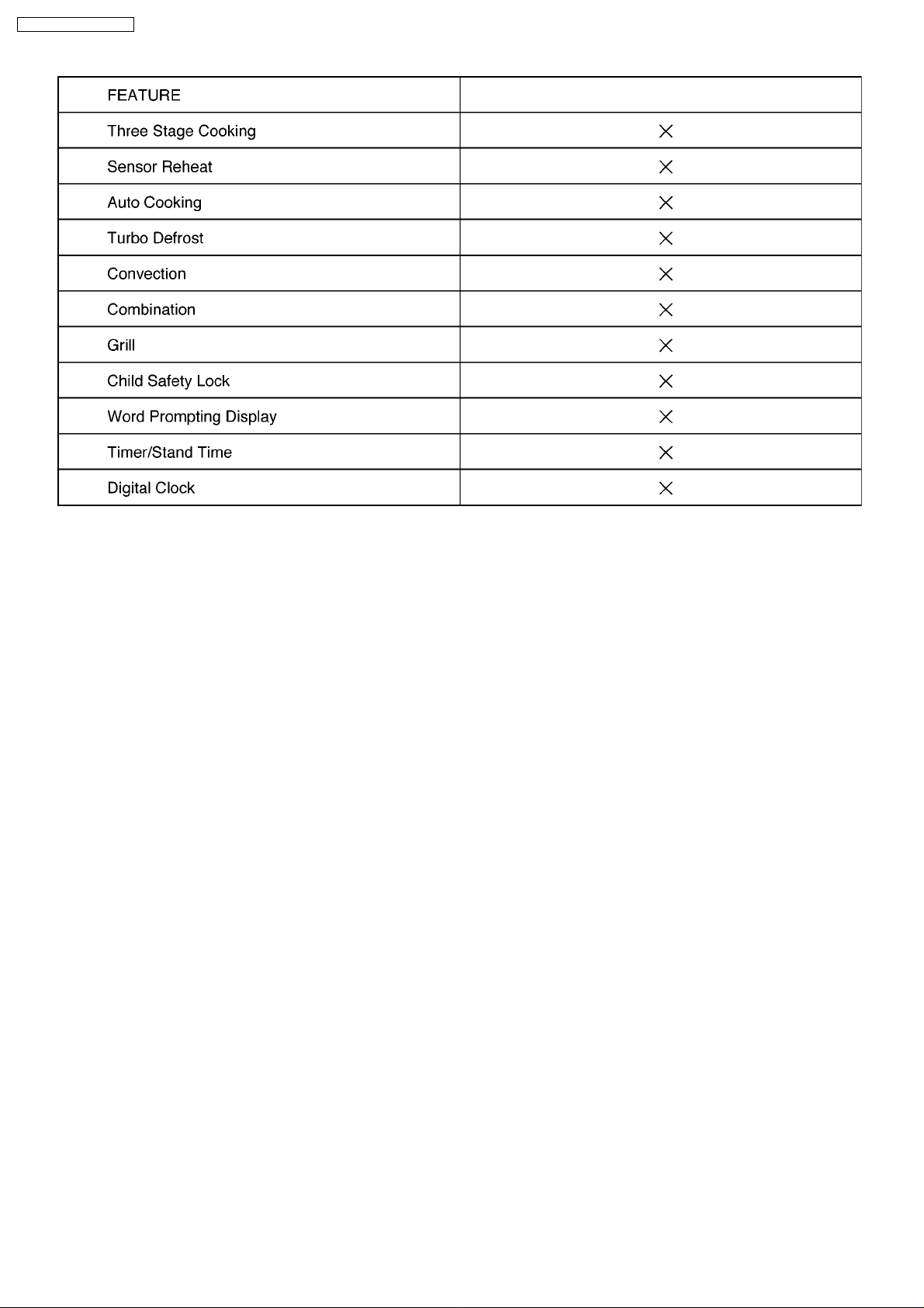
1 FEATURE CHART
4
Page 5
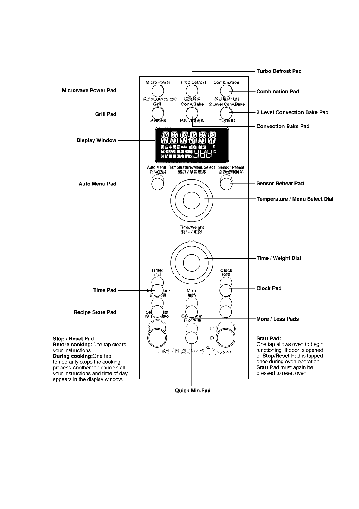
2 CONTROL PANEL
W
NN-C2000P / NN-C2000
5
Page 6
NN-C2000P / NN-C2000W
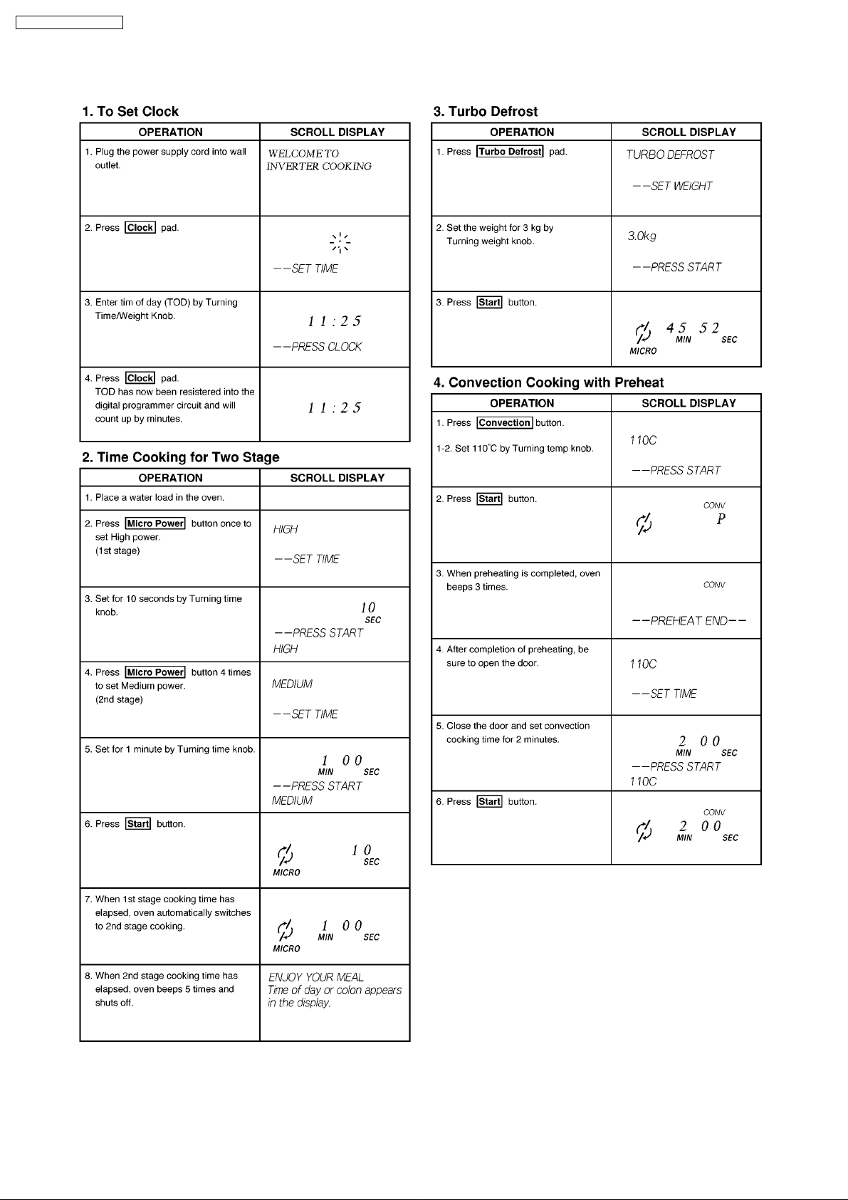
3 OPERATION AND DIGITAL PROGRAMMER CIRCUIT
TEST PROCEDURE
6
Page 7
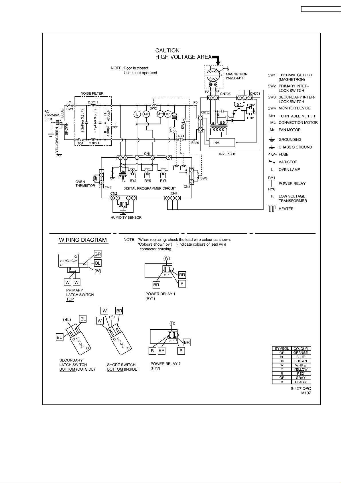
4 SCHEMATIC DIAGRAM (FOR QPQ, JPG)
W
NN-C2000P / NN-C2000
7
Page 8
NN-C2000P / NN-C2000W
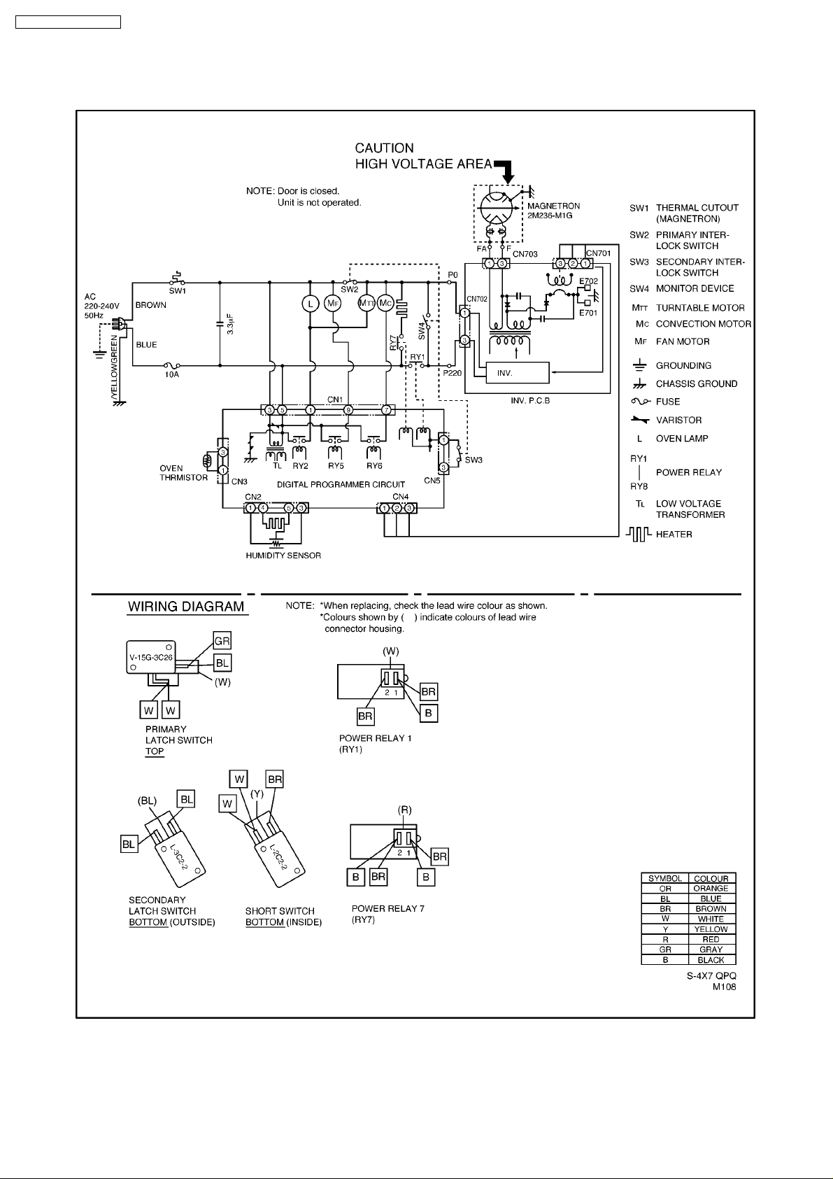
5 SCHEMATIC DIAGRAM (FOR MNQ, YNQ, TNE, LNK,
SNM, KNQ, KKE)
8
Page 9
6 DESCRIPTION OF OPERATING SEQUENCE
W
NN-C2000P / NN-C2000
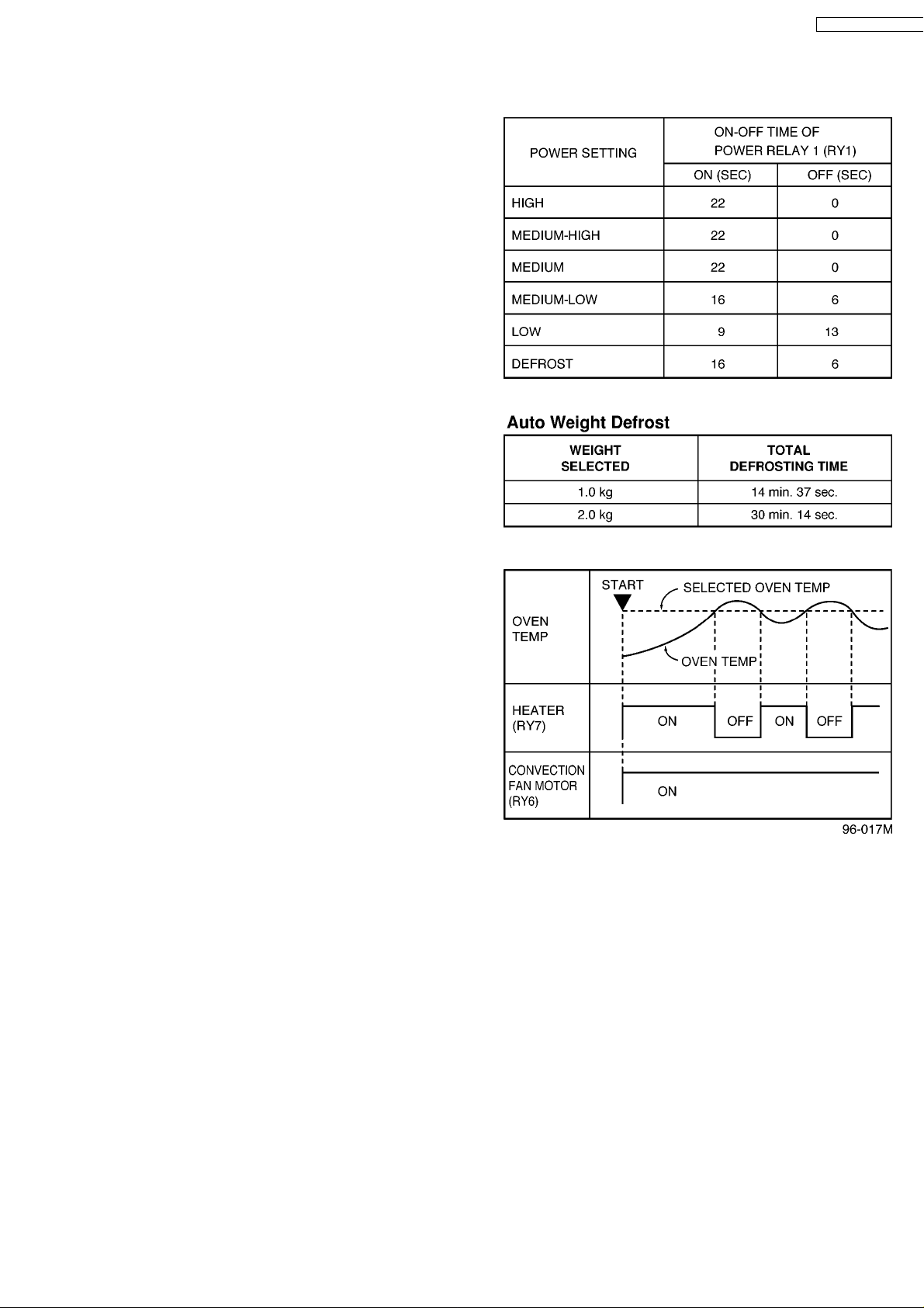
6.1. Variable power cooking
control
HIGH VOLTAGE INVERTER POWER SUPPLY (U) controls
output power by the signal from Digital Programmer Circuit
(DPC). Power relay 1 stays on but the inverter drive signal to
control it's output power.
NOTE: The ON/OFF time ratio does not correspond with
the percentage of microwave power since approximately 2
seconds are required for heating of magnetron filament.
6.2. Turbo weight defrost
When auto weight defrost is selected and the Start Pad is
tapped:
1. The digital programmer circuit determines the power level
and cooking time to complete cooking and indicates the
operating state in the display window. Table shows the
corresponding cooking times for respective serving by
categories.
2. When cooking time in the display window has elapsed, the
oven turns off automatically by a control signal from the
digital programmer circuit.
6.3. Convection/Grill cooking
control
NOTE: When Broil feature is selected, oven temperature is
determined automatically as shown in Figure.
The digital programmer circuit controls the ON-OFF time of the
heater in order to control oven cavity temperature.
1. After the start pad is tapped with the desired Bake/Broil
program set, an 18V DC signal comes out of the digital
programmer circuit and is applied to coil of power relay 7
(RY7).
2. When the contacts of power relay 7 close, power source
voltage is applied to the heater and the heater turns on.
3. When the oven temperature reaches the set temperature,
the digital programmer circuit senses the temperature
through oven temp sensor and stops supplying an 18V DC
signal to the coil of power relay 7 and the heater turns off.
4. After the heater turns off, the oven temperature will
continue increasing a while and then decrease as shown in
Figure. When the oven temperature drops below the set
temperature, the digital programmer circuit senses the
signal and starts supplying an 18V DC signal to the coil of
power relay again.
9
Page 10
NN-C2000P / NN-C2000W
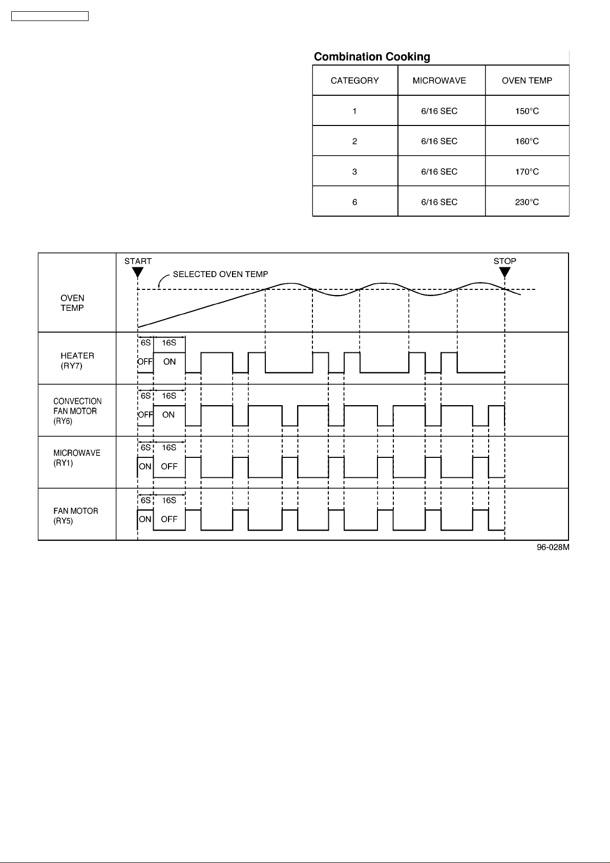
6.4. Combination cooking control
Combination cooking is accomplished by microwave and
convection cooking being done alternately during one
combination cooking cycle. One combination cooking cycle is
22 seconds.
1. During combination cooking, the digital programmer circuit
controls ON-OFF time of both power relay 1 and 7 as
shown in Figure.
2. When the power relay 1 (RY1) is turned on, heater turns off
and after the power relay 1turns off, power relay 7 turns on.
NOTE 1: Note that the heater may not be on during a heater
on period if the preprogrammed oven temperature has
been reached. This is due to the fact that the oven is
keeping the preprogrammed oven temperature constant,
so of course the heater will only be on when it is needed
and off when it is not needed.
NOTE 2: As for temperatures of combination cooking for
convection, the temperatures by each program are
preprogrammed in the microprocessor as shown in Figure.
6.5. One touch Auto sensor
cooking
Auto sensor cooking is a revolutionary way to cook by
microwave without setting a power level or selecting a time. All
that is necessary is to select an Auto sensor Program before
starting to cook.
Understanding of Cooking
As food cooks, a certain amount of steam is produced. If the
food is covered, this steam builds up and eventually escapes
from the container. In Auto Sensor Cooking, carefully designed
instrument, called the humidity sensor element, senses this
escape of steam. Then, based upon the Auto Sensor Program
selected, the unit will automatically determine the correct power
level and the proper length of time it will take to cook the food.
NOTE: Auto Sensor Cooking is successful with the foods
and recipes found in the Auto Sensor Cooking Guide.
Because of the vast differences in food composition, items
not mentioned in the Cooking Guide should be prepared in
the microwave oven using power select and time features.
Please consult Variable Power Microwave Cookbook for
procedures.
Explanation of the Auto Sensor Cooking process
1) The shaded columns in Figure indicate when the humidity
sensor heater is on.
2) During the 30 second period there is no microwave activity.
When calculating the T2 timeby using the formula below, make
sure this 30 seconds is subtracted from the T0 time.
3) T1 time To time - 30 seconds
4) T2 time When the steam escapes from the cooking
container placed in the oven, the humidity sensor detects it and
the microprocessor calculates the balance of cooking time.
This T2 time is then shown in the display and begins counting
down.
10
Page 11
Balance of cooking time (T2 time)
W
The balance of cooking time which is called T2 time, can be
calculated by the following formula.
T2 time (in sec.) = T1 time × K factor
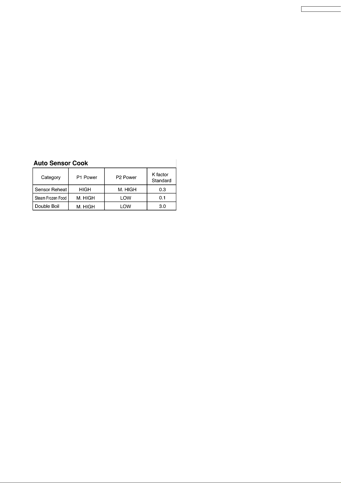
NOTE: Remember, the T1 time starts after the Start pad is
tapped. The coefficient K is programmed into the
microprocessor memory and they are listed in the
following tables along with the P1 and P2 powers.
NOTE: When "More" or "Less" pad is selected, the K factor
varies resulting in T2 time to be increased or decreased.
NOTE: For T2 time of Category Casserole, HEATER
operation programmed.
Example of calculating theT2 time
Example 1: If the T1 time is measured to be 2 minutes and 40
seconds, and the Auto Sensor program selected is Sensor
Reheat.
T2 = T1 × K
= 2 min. and 40 sec. × 0.3
= 48 sec.
NN-C2000P / NN-C2000
11
Page 12
NN-C2000P / NN-C2000W
7 CAUTIONS TO BE OBSERVED WHEN
TROUBLESHOOTING
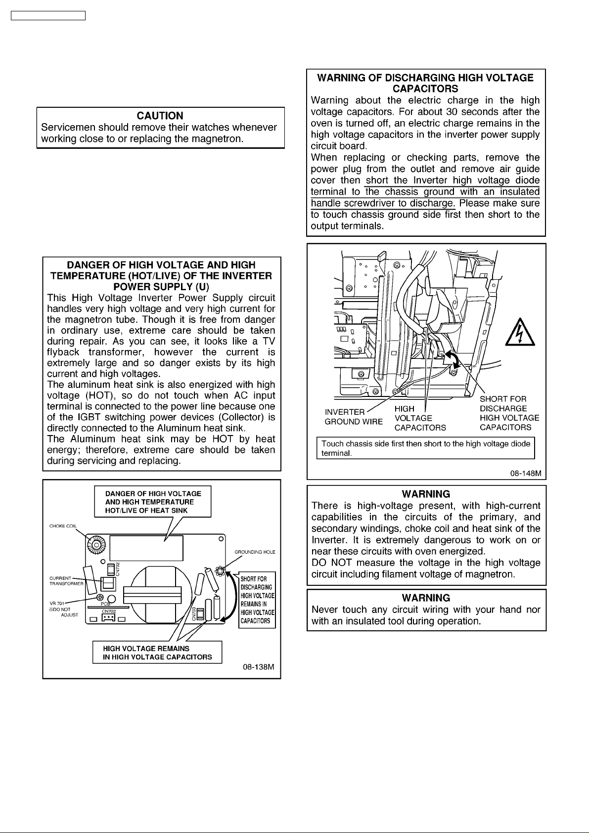
Unlike many other appliances, the microwave oven is highvoltage, high-current equipment. Though it is free from danger
in ordinary use, extreme care should be taken during repair.
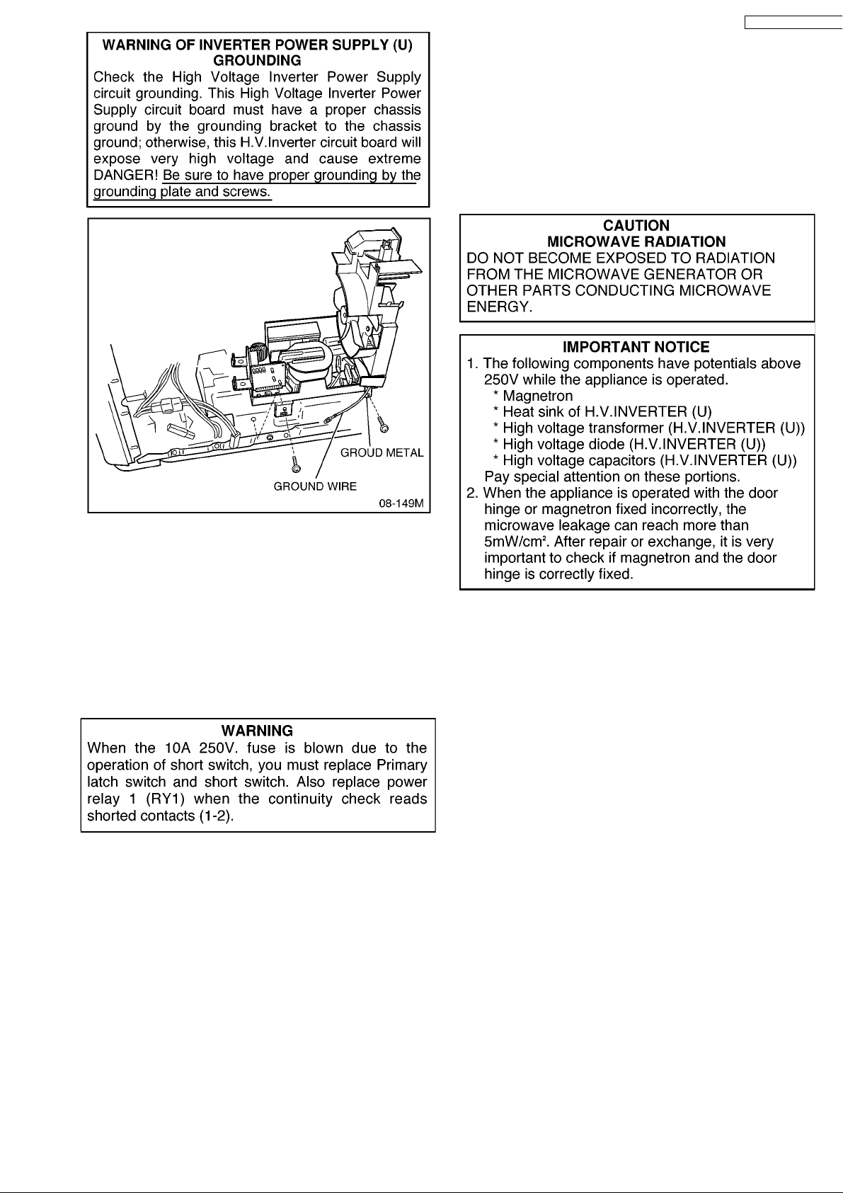
7.1. Check the grounding
Do not operate on a 2-wire extension cord. The microwave
oven is designed to be used when grounded. It is imperative,
therefore, to make sure it is grounded properly before
beginning repair work.
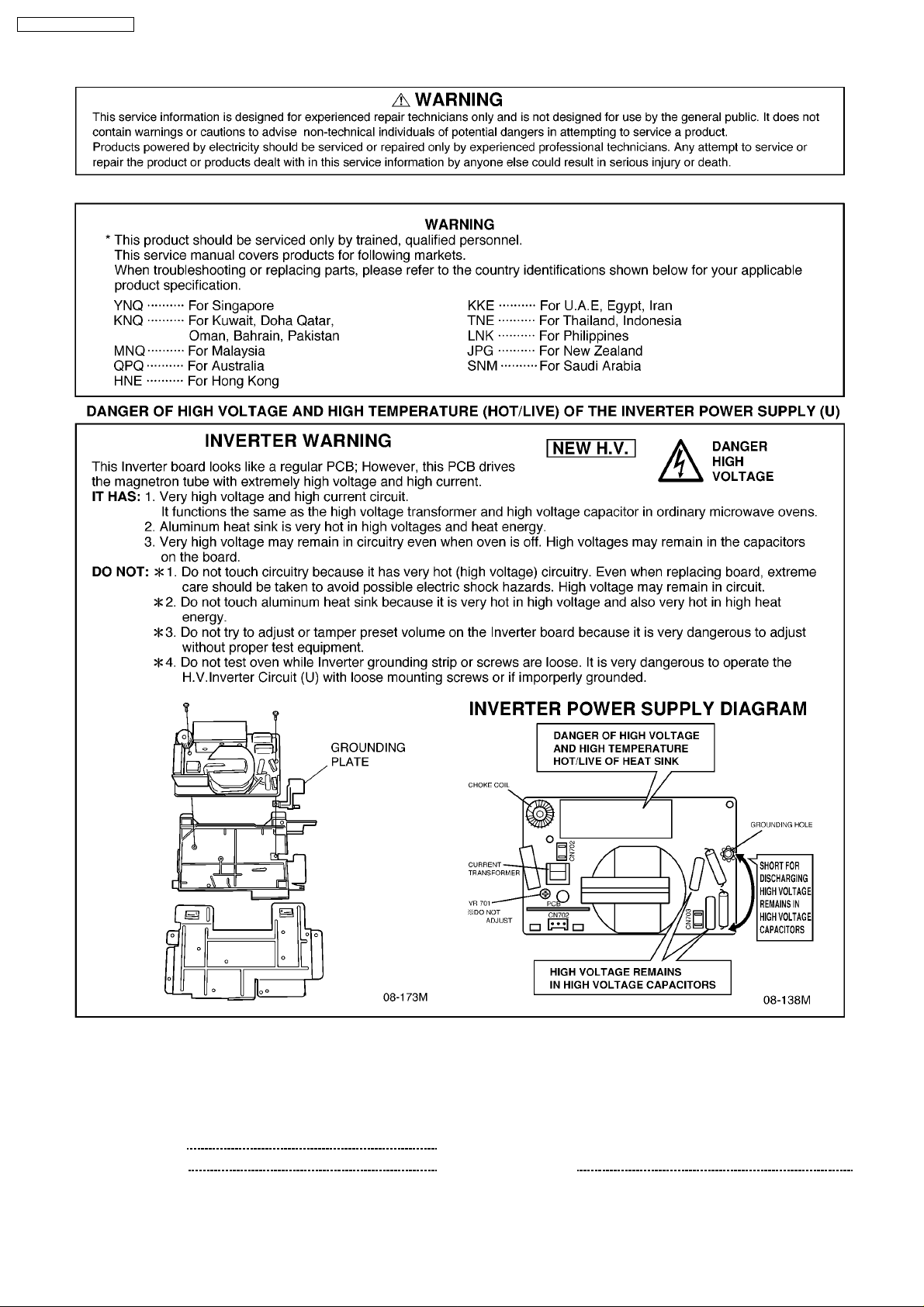
7.2. Inverter Warnings (NEW H.V.)
12
Page 13
NN-C2000P / NN-C2000
W
lamp holes on the cavity or any other holes gaps, because such
objects may work as an antenna and cause microwave
leakage.
7.6. Confirm after repair
1. After repair or replacement of parts, make sure that the
screws of the oven, etc. are neither loose nor missing.
Microwaves might leak if screws are not properly tightened.
2. Make sure that all electrical connections are tight before
inserting the plug into the wall outlet.
7.3. When parts must be replaced,
remove the power plug from
the outlet.
7.4. When the 10A 250V fuse is
blown due to the operation of
short switch:
1. This is mandatory. Refer to "Adjustments and
Measurement" for these switches.
2. When replacing the fuse, confirm that it has the appropriate
rating for these models.
3. When replacing faulty switches, be sure mounting tabs are
not bent, broken or otherwise deficient in their ability to hold
the switches.
7.5. Avoid inserting nails, wire, etc.
through any holes in the unit
during operation.
Never insert a wire, nail or any other metal object through the
13
Page 14

NN-C2000P / NN-C2000W
8 DISASSEMBLY AND PARTS REPLACEMENT
PROCEDURE
8.1. Magnetron
1. Discharge the high voltage capacitor.
2. Remove 2 screws holding magnetron thermal cutout
bracket.
3. Disconnect 2 high voltage lead wires from magnetron
filament terminals.
4. Remove 4 screws holding the magnetron.
NOTE: After replacement of the magnetron, tighten
mounting screws properly making sure there is no gap
between the waveguide and the magnetron to prevent
microwave leakage.
8.2. Digital programmer circuit
(DPC) and membrane key
board.
NOTE: Be sure to ground any static electric charge built up
on your body, before handling the DPC.
1. Disconnect all connectors from D.P.C.
2. Remove 3 screws holding escutcheon base and slide the
escutcheon base upward slightly.
3. Remove flat cable of CN5.
4. Remove 5 screws holding DPC.
To replace switch PCB.
5. Remove 2 knobs.
6. Remove 6 screws.
To replace buttons
1. Remove escutcheon bracket from escutcheon base by
freeing 6 catch hooks on the escutcheon base.
2. Replace whole button assembly.
8.3. Low voltage transformer
and/or power relays
NOTE: Be sure to ground any static electric charge built up
on your body before handling the DPC.
1. Using solder wick or a desoldering tool and 30W soldering
iron, carefully remove all solder from the terminal pins of the
low voltage transformer and/or power relays.
NOTE: Do not use a soldering iron or desoldering tool
of more than 30 watts on DPC contacts.
2. With all the terminal pins cleaned and separated from DPC
contacts, remove the defective transformer/power relays
and install new transformer/power relays making sure all
terminal pins are inserted completely. Resolder all terminal
contacts carefully.
14
Page 15

8.4. Fan motor
W
NN-C2000P / NN-C2000
1. Disconnect 2 lead wires from fan motor terminals.
2. Disconnect 2 lead wires from fuse holder terminals. (some
models)
3. Remove 4 screws holding fan motor and orifice assy and
detach the orifice assy with fan motor from oven assy.
4. Remove fan blade from the fan motor shaft by pulling it
straight out.
5. Separate the fan motor from the orifice assy by freeing 2
catch hooks on the orifice assy.
8.5. Heater
1. Remove lead wires from lead wire holders.
2. Remove belt from pulleys of circulation fan.
3. Remove 2 screws holding heater fan motor bracket.
4. Remove 1 screw holding exhaust guide.
5. Remove 2 screws holding oven temp sensor.
6. Disconnect 2 lead wires from heater terminals.
7. Remove 4 screws holding the both sides of heater unit and
lift it up carefully.
8. Remove 3 screws holding heater supports and detach the
heater.
8.6. Door assemble
1. Open the door and remove 4 screws holding door C.
15
Page 16

NN-C2000P / NN-C2000W
2. Remove the door C from door E bycarefully pulling outward
starting from upper right hand corner.
3. Separate the door A from the door E by freeing 8 catch
hooks on the door A.
4. Remove door key spring and door key.
After replacement of the defective component parts of the
door, reassemble it and follow the instructions below for
proper installation and adjustment so as to prevent an
excessive microwave leakage.
1. When mounting the door to the oven, be sure to adjust the
door parallel to the bottom line of the oven face plate by
moving the upper hinge and lower hinge in the direction
necessary for proper alignment.
2. Adjust so that the door has no play between the inner door
surface and oven front surface. If the door assembly is not
mounted properly, microwave may leak from the clearance
between the door and oven.
8.8. Inverter PCB
1. Remove 2 screws holding inverter bracket to oven chassis.
2. Remove A screw holding air guide.
3. Remove grounding lead wire.
4. Remove 2 screws holding noise filter PCB. (some models
only)
5. Remove all lead wires from inverter PCB.
6. Slide left and take out inverter PCB with brackets.
7. Remove A screw holding inverter PCB to bracket from
bottom.
8. Remove 3 screws holding inverter PCB to bracket.
9. Remove inverter PCB from its bracket by releasing several
catch hooks.
10. When re-install, make sure to place grounding plate in its
place.
8.7. Turntable motor
1. Remove 2 screws holding motor cover.
2. Disconnect 2 lead wires from turntable motor.
3. Remove 2 screws holding turntable motor.
16
Page 17

Missing grounding is very danger.
W
NN-C2000P / NN-C2000
17
Page 18

NN-C2000P / NN-C2000W
9 COMPONENT TEST PROCEDURE
9.1. Primary Latch Switch,
Secondary (Secondary Latch
Switch and Power Relay 1)
Interlocks.
1. Unplug the lead connectors to Power Relay 1 and verify
continuity of the power relay 1 1-2 terminals.
2. Unplug lead connectors to Primary Latch Switch and
Secondary Latch Switch.
3. Test the continuity of switches at door opened and closed
positions with ohm meter (low scale).
Normal continuity readings should be as follows.
9.3. Magnetron (NEW H.V.)
Continuity checks can only indicate an open filament or a
shorted magnetron. To diagnose for an open filament or
shorted magnetron.
1. Isolate magnetron from the circuit by disconnecting the
leads.
2. A continuity check across magnetron filament terminals
should indicate one ohm or less.
3. A continuity check between each filament terminal and
magnetron case should read open.
9.4. Membrane key board
(Membrane switch assembly)
Check continuity between switch terminals, by tapping an
appropriate pad on the key board. The contacts assignment of
the respective pads on the key board is as shown in digital
programmer circuit.
9.2. Short Switch / Monitor Circuit
1. Unplug lead wires from H. V. Inverter primary terminals.
2. Connect test probes of ohm meter to the disconnected
leads which were connected to H. V. Inverter.
3. Test the continuity of short switch with door opened and
closed positions using lowest scale of the ohm meter.
Normal continuity readings should be as follows.
18
Page 19

9.5. Inverter Power Supply (U)
W
(NEW H.V.)
NN-C2000P / NN-C2000
DO NOT try to REPAIR this H. V. Inverter power supply (U).
Replace as whole H. V. Inverter (U) Unit.
Refer to warning on page 2.
9.6. Inverter Power Supply (U)
(NEW H,V,)
DANGER HIGH VOLTAGE
Test 1
1. Place 1 liter of water load into oven cavity.
2. Unplug 2 pin H. V. lead wire connector CN703 from
magnetron tube.
3. Program oven at High power for 1 minute and press start.
a. After approx. 23 seconds, oven stops.
b. During oven operation, input current is approx. at 0.5 to
1.0A . If input current is OK, please proceed to test 2.
Test 2
Continued from Test 1
1. Unplug 3 pin connector, CN701 CN703 remaisn unplug.
2. Set oven at High power for 1 minute and start.
a. After approx. 3 seconds, oven.
b. During oven operation, input current should be lessthan
0.4A.
If both 1 and 2 are OK, the Inverter Power Supply (U) can be
determined OK.
9.7. Steam Sensor and Digital
Programmer Circuit
In order to determine if the steam sensor function of the digital
programmer circuit is in working order or not, do the following
test.
1. Place a water load (150 cc) in the oven.
2. Tap Sensor Reheat pad.
3. Tap Start Pad.
4. Steam Sensor detects steam about 1.5 to 4 minutes after
the Start Pad is tapped.
5. T1 time cooking automatically switches to remaining time
cooking (T2).
6. The remaining cooking time (T2) appears in display
window. If the following cooking time appears, Steam
Sensor function is normal.
9.8. Oven temp sensor thermistor
This sensor monitors the heat produced by the heater circuit
and maintains the oven temperature the user had selected.
Normal room 10°C to 30°C. The reading across the oven
sensor thermistor should be within 100K ohm to 300K ohm
when reading in an area with the 50°F to 90°F room
temperature range.
If the resistance reading is out of the range stated here, the
sensor is detective and must be replaced.
NOTE 1: When measuring resistance disconnect the 3-pin
19
Page 20

NN-C2000P / NN-C2000W
connector (CN6) from the DPC otherwise a false reading
may be indicated.
NOTE 2: If checking an oven sensor thermistor just after
the microw ave oven has been operating, the sensor of
course won't be room temperature. In this case the sensor
must be removed and allowed to cool down to the 10°C to
30°C range.
9.9. Humidity Sensor and digital
programmer circuit
1. Check across sensor heater terminals. Normal cold
resistance should read approx. 4.5 ohm.
2. In order to determine if the Auto/Humidity Sensor function
of the digital programmer circuit is in working order or not,
do the following test.
a. Place a water load in the oven.
b. Unsolder 2 black wires connected to sensor terminals.
c. Tap Sensor Reheat Pad to set auto sensor cooking and
tap Start Pad.
d. About 10 seconds after Start Pad is touched, short 2
black wires for 5 seconds and then remove them.
Before shorting the 2 black wires you can watch the
sensor heater glow red.
e. Approx. 75 seconds after the Start Pad is pressed (T0
TIME), short the 2 black wires again.
f. "AUTO" should disappear in display window and
following digits (see chart) should appear indicating
**balance of cooking time (T2 TIME). The time should
start to count down and oven should shut off when the
time has elapsed.
the microw ave oven has been operating, the sensor of
course won't be room temperature. In this case the sensor
must be removed and allowed to cool down to the 50°F to
90°F range.
The Auto Sensor function in the digital programmer circuit is
working in order if above condition is obtained.
9.10. Oven temp sensor thermistor
This sensor monitors the heat produced by the heater circuit
and maintains the oven temperature the user had selected.
Normal room temperature, especially in a kitchen can vary
anywhere from 10°F to 30°F. The reading across the oven
sensor thermistor should be within 100K ohm to 500K ohm
when reading in an area within the 10°F to 30°F room
temperature range.
If the resistance reading is out of the range stated here, the
sensor is detective and must be replaced.
NOTE 1: When measuring resistance disconnect the 4-pin
connector (CN3) from the DPC otherwise a false reading
may be indicated.
NOTE 2: If checking an oven sensor thermistor just after
20
Page 21

10 MEASUREMENTS AND ADJUSTMENTS
W
NN-C2000P / NN-C2000
10.1. Adjustment of Primary latch
switch, Secondary latch
switch and short switch
1. When mounting Primary latch switch, Secondary latch
switch and short switch to door hook assembly, mount the
Primary latch switch, the Secondary latch switch and the
short switch to the door hook assembly as shown in table.
NOTE: No specific adjustment during installation of
Primary latch switch, Secondary latch switch and short
switch to the door hook is necessary.
2. When mounting the door hook assembly to the oven
assembly, adjust the door hook assembly by moving it in
the direction of arrow in table so that the oven door will not
have any play in it. Check for play in the door by pulling the
door assembly. Make sure that the latch keys move
smoothly after adjustment is completed. Completely tighten
the screws holding the door hook assembly to the oven
assembly.
3. Reconnect the short switch and check the continuity of the
monitor circuit and all latch switches again by following the
components test procedures.
10.2. Measurement of microwave
output
The output power of the magnetron can be determined by
performing IEC standard test procedures. However, due to the
complexity of IEC test procedures, it is recommended to test
the magnetron using the simple method outlined below.
Necessary Equipment:
*1 liter beaker *Glass thermometer
*Wrist watch or stopwatch
NOTE: Check the line voltage under load. Low voltage will
lower the magnetron output. Take the temperature
readings and heating time as accurate as possible.
1. Fill the beaker with exactly one liter of tap water. Stir the
water using the thermometer and record the beaker ユ s
temperature (recorded as T1).
2. Place the beaker on the center of glass cook plate. Set the
oven for High power and heat it for exactly one minute.
3. Stir the water again and read the temperature of the beaker
(recorded as T2).
4. The normal temperature rise at High power position for
each models is as shown in table.
21
Page 22

NN-C2000P / NN-C2000W
11 TROUBLESHOOTING GUIDE (NEW H.V.)
22
Page 23

NN-C2000P / NN-C2000
W
23
Page 24

NN-C2000P / NN-C2000W
24
Page 25

NN-C2000P / NN-C2000
W
1. Discharge high voltage before touching Inverter PCB.
1. Unplug oven and leave it for more than 30 seconds before
removing outer cabinet.
2. Use insulated lead wire to short across D701 Anode to
D702 Cathode or short across magnetron filament
terminals to the chassis ground. Please refer to service
manual for detail of the specified model.
2. Remove inverter PCB from oven before troubleshooting.
Refer to related service manual for inverter PCB removal.
1. Visual check:
a. PCB board: Any crack on board, burnt printed copper
foil pattern? Any cockroach, bugs excrements, any mark
of wet?
b. Components: Any damaged components? Any burnt,
broken or missing?
3. Check component by circuit tester.
25
Page 26

NN-C2000P / NN-C2000W
1. How to check power transistors (Q701, Q702). To measure,
suck a solder from its legs completely unless faulse reading
may observe and mislead a troubleshooting. Measure
across pins between E-C, E-G, C-G, E-black lead, C-red
lead of tester should be infinite and may have some reading
in reverse, it is normal. Refer to attached table for normal
reading.
2. DB701 Diode Bridge
3. C704, C705 High voltage Capacitors. D702 and C705,
D701 and C704 are parallel connected therefore, remove
component to measure when diode is shorted.
4. D701, D702 High voltage Diodes
4. How toreplace power transistors Q701, Q702 and Bridge
Diode DB701.
1. To remove Q701, Q702 and DB701 unsolder their legs first,
next remove ascrew that holding the heatsink onto the PCB
then dtach the heatsink as shown below.
Service Hints: For easy solder removal, use one soldering
iron to heat a solder and use solder sucker iron to suck
solder.
2. Make sure to replace both Q701 and Q702 at a time with
the same maker.
3. Make sure to apply heat conduction grease between
transistor and heat sink.
4. NO DUST SHOULD CAUGHT between heat sink and
power transistor unless if causes looseness of heat
conduction and insufficient cooling to blow components.
26
Page 27

5. Screw must be tighten securely.
W
6. Install the heatsink onto the PCB by a screw and make
sure to apply extra solder between legs and PCB pattern
so that it's able to flow 15A or more main current.
NN-C2000P / NN-C2000
7. Apply extra solder onto Q701 and Q702 legs and printed
foil pattern to be able to hold main large current of more
than 15A.
Service hint:
For easy removal of solder, apply some solder first than suck it
all.
8. How to test repaired Inverter PCB.
WARNING:
1. Do not test Inverter PCB with using any extention cable
Open gounding of inverter PCB is so DANGER.
2. Make sure to check no Bridge solder nor cold solder joint.
1. Install Inverter PCB into oven with screws securely, plug in
CN701, CN702 and CN703.
2. Insert AC plug through the Amper meter with specified
voltage.
NOTE: Current will be changed by the input AC voltage.
3. Operate the oven at High power setting for 1 minute.
4. Read input current which should be within oven
specification.
NOTE: Input current will be decreased after a certain
cooking period.
5. Adjustment is not necessary when replacing transistors
You may adjust the preset volume control VR701 to meet
the specified input current when Transformer is replaced.
27
Page 28

NN-C2000P / NN-C2000W
28
Page 29

NN-C2000P / NN-C2000
W
12 HOW TO CHECK THE SEMICONDUCTORS USING AN
OHM METER
29
Page 30

NN-C2000P / NN-C2000W
13 EXPLODE D VIEW AND PARTS LIST
30
Page 31

14 PARTS LIST
W
NN-C2000P / NN-C2000
When ordering replacement part(s) please use part number(s) shown in this parts list.
Do not use description of the part.
Important safety notice:
Components identified by
mark have special characteristics important for safety.
When replacing any of these components, use only manufacturer's specified parts.
Alphabet marks in Remarks colums (l. e. HNE etc.) indicate parts applicable to only specified country models as follows.
HNE: For Hong Kong, JPG: For New Zealand, KKE: For U.A.E., Egypt, Iran,
KNQ: For Kuwait, Doha, Qatar, Oman, Baharain, Pakistan, LNK: For Philippines,
MNQ: For Malaysia, QPQ: For Australia, SNM: For Saudi Arabia,
TNE: For Thailand, Indonesia, YNQ: For Singapore
Parts without these marks can be used for all models.
Ref.
No.
1 ANE00057J0XN EARTH LABEL 1 NN-C2000P TNE
2 A00065460JP CAUTION LABEL 1
2 A00065540MN CAUTION LABEL 1 NN-C2000P YNQ
3 ANE0033730GN FUSE LABEL 1 NN-C2000P
4 ANE0239L00XN CORD LABEL 1 NN-C2000P KKE/KNQ/SNM
5 ANE0902000CA CUSHION RUBBER A 1
6 ANE0921000BK CUSHION RUBBER C 1
7 ANE0924000AQ CUSHION RUBBER C 1
7 ANE0924000AQ CUSHION RUBBER C 1
8 ANE0922000DD CUSHION RUBBER C 1
9 ANE0902000AV CUSHION RUBBER A 1
10 ANE0924000GE CUSHION RUBBER C 1
11 A10014X00AP BASE 1
12 ANE1008-3W0 RUBBER FOOT 4
12 ANE1008-3W0 RUBBER FOOT 4
12 ANE1008-3W0 RUBBER FOOT 4
12 ANE1008-3W0 RUBBER FOOT 4
13 A10094X70GMN CABINET BODY 1 NN-C2000P
13 A10094X70HQP CABINET BODY 1 NN-C2000W
14 A10266660QP BASE C 1
15 A11294X00AP BASE B 1
16 A11406660QP STOPPER 2
16 A11406660HMK STOPPER 2 NN-C2000P YNQ
17 A200A4X00AP OVEN 1
18 ANE22392L0AP CIRCULATION FAN 1
19 A20554X00AP COVER 1
20 A20764X00AP REINFORCE BRACKET C 1
21 A21315870GP PULLEY SHAFT 1
22 ANE2177-F80 WASHER 1
23 A22365450AP RIGHT HEATER PANEL 1
24 A290D4J00XN ROLLER RING (U) 1
25 A30076660QP LOWER HINGE 1
26 A3020-1200 DOOR HOOK A 1
27 A3136-1200 HOOK SPACER A 1
28 A31374650AP HOOK SPACER B 1
29 A31384650AP HOOK SPACER C 1
30 A400A5500QP FAN MOTOR 1 NN-C2000P HNE/KKE/KNQ/MNQ/SNM/TNE/YNQ NN-C2000W (24.8W)
30 A400A4000LN FAN MOTOR 1 NN-C2000P LNK (26W)
31 A400K5040AQ EXHAUST GUIDE 1
32 ANE40086W0AP FAN 1
33 A40085020AQ FAN 1
34 A40256660QP AIR GUIDE A 1
35 A40264X00AP AIR GUIDE B 1
36 A40306660QP AIR GUIDE D 1
37 A40474X00AP AIR GUIDE E 1
38 ANE4057-F50 SPRING 1
39 A40606660QP BELT 1
40 A41206660QP EXHAUST COVER 1
41 A41446660SN ORIFICE 1
42 A41799190QP HEATER FAN MOTOR 1 NN-C2000P HNE/KKE/KNQ/MNQ/TNE/YNQ NN-C2000W (16W)
42 A41795080BP HEATER FAN MOTOR 1 NN-C2000P LNK/SNM (35/33.5W)
43 A41804X00AP HEATER FAN MOTOR BRACKET 1
44 A601L4780AP HUMIDITY SENSOR 1
Part No. Part Name & Description Pcs/
Set
Remarks
31
Page 32

NN-C2000P / NN-C2000W
Ref.
No.
45 A60304080BP INCANDESCENT LAMP 1 (20W/240V)
46 A605A4X70QP THERMISTOR 1
47 A606Y4V00GP H.V.INVERTER (U) 1
48 ANE6142-F60 MICRO SWITCH 2 (V-15G-3C26-1) (PRIMARY)
49 A61425180AP MICRO SWITCH 2 (L-3C2-2) (SECONDARY)
50 A61456670AP THERMAL CUTOUT 1
51 A61524650AP SOCKET 1
52 A61785180AP MICRO SWITCH 2 (L-2C2-2) (SHORT SW)
53 A62304210BP FUSE 1 (10A/250V)
53 A62304210BP FUSE 1 (10A/250V)
54 A62314000AP FUSE HOLDER 1 NN-C2000P
55 A63266660HN TURNTABLE MOTOR 1 NN-C2000P HNE/KKE/LNK/SNM/TNE (3.3W)
55 A63265850QP TURNTABLE MOTOR 1 NN-C2000P KNQ/MNQ/YNQ NN-C2000W (2.5W)
56 A6585-1B10 P.C.B.HOLDER A 1
57 A66036000BP OVEN LAMP BRACKET 1
58 A6662-1880 EARTH SPACER 1
59 A67634X00AP P.C.B.HOLDER B 1
60 A67974X00CP P.C.B.HOLDER C 1 NN-C2000W
61 A692Y4T00QP NOISE FILTER (U) 1 NN-C2000W
62 A900C6660HN AC CORD W/PLUG 1 NN-C2000P HNE (220-240V)
62 A900C5450MK AC CORD W/PLUG 1 NN-C2000P KKE/KNQ/MNQ/YNQ (220-240V)
62 A900C6240CP AC CORD W/PLUG 1 NN-C2000P LNK (230-240V)
62 A900C9770SN AC CORD W/PLUG 1 NN-C2000P SNM (220-240V)
62 A900C5450TN AC CORD W/PLUG 1 NN-C2000P TNE (220V)
62 A900C6660JP AC CORD W/PLUG 1 NN-C2000W (240V)
63 XST4+5VS SCREW 1 4X5 (FOR COVER)
64 XTT4+8RDN SCREW 1 4X8 (FOR CABINET BODY)
65 XTWANE3+10S4 SCREW 1 3X10 (FOR LAMP SOCKET)
66 XTWANE4+10RU SCREW 4 4X10 (FOR MAGNETRON)
66 XTWANE4+10RU SCREW 4 4X10 (FOR MAGNETRON)
67 XTWA3+8CF SCREW 1 3X8 (FOR INVERTER EARTH)
68 XTW3+18B SCREW 4
69 XYD4+EE12F SCREW 1 4X12 (FOR EARTH)
70 2M236-M1G MAGNETRON 1
71 ANE6501-C41 HEATER HOLDER C 2
72 XWS4VL WASHER 2
73 A21446660QP UPPER PANEL 1
74 A21776660QP WASHER 1
75 A22784X00AP UPPER HEATER PANEL 1
76 A41325020AQ PULLEY B 1
77 A41575450AP FAN BRACKET A 1
78 A41585450AP FAN BRACKET B 1
79 A41635020AQ FAN SPACER C 1
80 A400S6660QP SHAFT U 1
81 A630G6660QP HEATER A 1 NN-C2000P MNQ/YNQ/KNQ NN-C2000W QPQ
81 A630G6660HN HEATER A 1 NN-C2000P HNE/LNK/TNE/SNM/KKE
81 A630G6660JP HEATER A 1 NN-C2000W JPG
82 A64175130AP HEATER SUPPORT 3
82 A64175130AP HEATER SUPPORT 3
82 A64175130AP HEATER SUPPORT 3
83 XTWANE35+14N SCREW 3 3.5X14 (FOR HEATER SUPPORT)
83 XTWANE35+14N SCREW 3 3.5X14 (FOR HEATER SUPPORT)
84 XNG4EVS NUT 2
84 XNG4EVS NUT 2
85 A41074X70QP EXHAUST GUIDE B 1
85 A41074X70QP EXHAUST GUIDE B 1
86 A01574X70HN NAME LABEL 1 NN-C2000P HNE
86 A01574X70KK NAME LABEL 1 NN-C2000P KKE
86 A01574X70KN NAME LABEL 1 NN-C2000P KNQ
86 A01574X70LN NAME LABEL 1 NN-C2000P LNK
86 A01574X70MN NAME LABEL 1 NN-C2000P MNQ
86 A01574X70SN NAME LABEL 1 NN-C2000P SNM
86 A01574X70TN NAME LABEL 1 NN-C2000P TNE
86 A01574X70YN NAME LABEL 1 NN-C2000P YNQ
86 A01574X70QP NAME LABEL 1 NN-C2000P QPQ
86 A01574X70JP NAME LABEL 1 NN-C2000P JPG
87 A02444X70QP CAUTION LABEL 1
88 A09254X70QP CUSHION RUBBER C 1
89 ANE0922000AQ CUSHION RUBBER C 1
Part No. Part Name & Description Pcs/
Set
Remarks
32
Page 33

15 DOOR ASSEMBL Y
W
NN-C2000P / NN-C2000
Ref.
No.
D1 ANE0245X00AP DHHS LABEL 1 NN-C2000P LNK
D1 A01726210JP CAUTION LABEL 1 NN-C2000W JPG
D2 XTBANE4+12FK SCREW 4 4X12(FOR DOOR C)
D2 XTBANE4+12FK SCREW 4 4X12(FOR DOOR C)
D3 A300B5450AP UPPER HINGE 1
D4 A302K6660QP DOOR E(U) 1
D5 A30186660QP DOOR KEY A 1
D6 A30214000AP DOOR KEY SPRING 1
D7 A30856660QP DOOR C 1
D8 A302A4X70GMN DOOR A (U) 1 NN-C2000P HNE/LNK/MNQ/TNE/YNQ (NOTE 1)
D8 A302A4X70GKN DOOR A (U) 1 NN-C2000P KKE/KNQ/SNM (NOTE 1)
D8 A302A4X70HQP DOOR A (U) 1 NN-C2000W QPQ (NOTE 1)
Part No. Part Name & Description Pcs/
Set
NOTE 1: Please order DHHS LABEL or CAUTION LABEL together.
Remarks
33
Page 34

NN-C2000P / NN-C2000W
16 ESCUTCHEON BASE ASSEMBLY
Ref.
No.
E1 A02840000MK NUMBER LABEL 1 NN-C2000P YNQ
E2 A603Y4X70QP PC BOARD D (U) 1 NN-C2000P NN-C2000W QPQ
E3 A605Q4X70HN PC BOARD F (U) 1 NN-C2000P HNE (W/COMPONENT)
E3 A605Q4X70SN PC BOARD F (U) 1 NN-C2000P KKE/SNM (W/COMPONENT)
E3 A605Q4X70KN PC BOARD F (U) 1 NN-C2000P KNQ (W/COMPONENT)
E3 A605Q4X70LN PC BOARD F (U) 1 NN-C2000P LNK (W/COMPONENT)
E3 A605Q4X70MN PC BOARD F (U) 1 NN-C2000P MNQ (W/COMPONENT)
E3 A605Q4X70TN PC BOARD F (U) 1 NN-C2000P TNE (W/COMPONENT)
E3 A605Q4X70YN PC BOARD F (U) 1 NN-C2000P YNQ (W/COMPONENT)
E3 A605Q4X70QP PC BOARD F (U) 1 NN-C2000W QPQ (W/COMPONENT)
E3 A605Q4X70JP PC BOARD F (U) 1 NN-C2000W JPG (W/COMPONENT)
E4 A6590-3280 FLAT CABLE 1
E5 A80094X70QP INDICATOR A 1
E5 A80094X70QP INDICATOR A 1
E6 A80204X70QP TIMER KNOB 2
E7 A80244X70QP OPERATION BUTTON 1
E8 A80344X70GMN ESCUTCHEON BASE 1 NN-C2000P (NOTE 2)
E8 A80344X70HQP ESCUTCHEON BASE 1 NN-C2000W (NOTE 2)
E9 ANE80378A0AG SPRING 1
E10 A80724X70GMN DOOR OPENING BUTTON 1 NN-C2000P
E10 A80724X70HQP DOOR OPENING BUTTON 1 NN-C2000W
E11 A81274X70QP BACK PANEL 1
E12 A82569770AP DOOR OPENING LEVER 1
E13 A82874X70QP SPACER A 2
E13 A82874X70QP SPACER A 2
E14 A83374X70GMN ESCUTCHEON SHEET 1 NN-C2000P HNE/LNK/MNQ/TNE/YNQ
E14 A83374X70GKN ESCUTCHEON SHEET 1 NN-C2000P KKE/KNQ/SNM
E14 A83374X70HQP ESCUTCHEON SHEET 1 NN-C2000W
Part No. Part Name & Description Pcs/
Set
Remarks
NOTE 2: Please order NUMBER LABEL together.
34
Page 35

17 PACKING AND ACCESORIES
W
NN-C2000P / NN-C2000
Ref.
No.
P1 A000B4X70MN COOK BOOK 1 NN-C2000P HNE/LNK/MNQ/TNE/YNQ
P1 A000B5820KN COOK BOOK 1 NN-C2000P KKE/KNQ/SNM
P2 A00034X70HN INSTRUCTION BOOK 1 NN-C2000P HNE/LNK/MNQ/TNE/YNQ
P2 A00034X70KN INSTRUCTION BOOK 1 NN-C2000P KKE/KNQ/SNM
P2 A00034X70QP INSTRUCTION BOOK 1 NN-C2000W
P3 A00324040XN EARTH CAUTION LABEL 1 NN-C2000P TNE
P4 A01024X70HMN PACKING CASE PAPER 1 NN-C2000P HNE/LNK/MNQ/TNE/YNQ
P4 A01024X70HKN PACKING CASE PAPER 1 NN-C2000P KKE/KNQ/SNM
P4 A01024X70HQP PACKING CASE PAPER 1 NN-C2000W QPQ
P4 A01024X70HJP PACKING CASE PAPER 1 NN-C2000W JPG
P5 A01046660MN UPPER FILLER 1 NN-C2000P HNE/LNK/MNQ/TNE/YNQ
P5 A01046660KN UPPERFILLER 1 NN-C2000P KKE/KNQ/SNM
P5 A01046660QP UPPER FILLER 1 NN-C2000W
P6 A01056660MN LOWER FILLER 1 NN-C2000P HNE/LNK/MNQ/TNE/YNQ
P6 A01056660KN LOWER FILLER 1 NN-C2000P KKE/KNQ/SNM
P6 A01056660QP LOWER FILLER 1 NN-C2000W
P7 A01065130AP VINYL COVER 1
P8 ANE0107580AP DOOR SHEET 1
P9 A01086660QP TRAY PACKING 1
P10 A01136660QP TRAY STYROL 1
P11 A01265820HKN REINFORCE MATERIAL 1 NN-C2000P KKE/KNQ/SNM
P12 ANE02072L0AP STYROL SHEET 1
P13 A04454X70MN MENU LABEL 1 NN-C2000P MNQ
P14 A060V4X00AP HIGH BAKING RACK 1 MID(50MM)
P15 A060V4X00CP HIGH BAKING RACK 1 HIGH(135MM)
P16 A06014X70QP COOKING TRAY 1
P17 A91644000XN EARTH LEAD 1 NN-C2000P TNE
P18 A01459770KN DOOR SHEET B 1
Part No. Part Name & Description Pcs/
Set
Remarks
35
Page 36

NN-C2000P / NN-C2000W
18 WIRING MATERIAL
Ref.
No.
W1 A030A4X70MN LEAD WIRE HARNESS 1 NN-C2000P
W1 A030A4X70QP LEAD WIRE HARNESS 1 NN-C2000W
W2 A030E4X00AP LEAD WIRE 1 NN-C2000P
W2 A030E4X00CP LEAD WIRE 1 NN-C2000W
W3 A03509770LN LEAD WIRE 1 NN-C2000P LNK
W4 A03536660QP LEAD WIRE 1
W5 AECQJ5335KRP CAPACITOR 1 3.3MF
Part No. Part Name & Description Pcs/
Set
Remarks
36
Page 37

19 REF. NO. 47 H. V. INVERTER (U)
W
Ref.
No.
C701 ECWF5104N300 FILM CAPACITOR 1 0.1MF 500VDC
C702 ECQE2405T847 POLYESTER CAPACITOR 1 4MF 250VDC
C703 ECWF5454N300 FILM CAPACITOR 1 0.45MF
C704
705
CN701 AEEMXH00703G CONNECTOR 1
CT701 A66904T00AP TRANSFORMER 1
D701
702
D703 AEDNERA3806 DIODE SI 0.5A 1 ERA38-06
D704
705
D706 MA196-(TA5) DIODE SI 0.1A 1 MA196
DB701 AESTRBV6206 DIODE SI 15A 1 15A 600V
DB701 XTW3+12B SCREW 2 3X12
H.S. A66914T00AP HEAT SINK 1
IC702
703
IC801 AN9DB07SB IC 1
L701 A50204T00AP COIL 1
Q701 AESCGT60M303 TRANSISTOR SI 170W 1
Q702 AESPGT30J322 TRANSISTOR SI 75W 1 GT30J322
Q702 XTN3+12B SCREW 1 3X12
Q703
704
Q705 2SA1309AQSTA TRANSISTOR SI 1 2SA1309AQRS
R701 AERG419S107M 1
R715 AERGS215J452 RESISTOR 1 4.5KΩΩΩΩ 15W
T701 A609A4V00GP INERTER TRANS. 1 P20T S296T
VR701 AEVTZ6TLT102 VARIABLE RESISTOR 1 1KΩΩΩΩ 30%
ZD701
703
704
705
ZD702 AESZ12JS2T1 ZENNER DIODE SI 1 RD12JS2
Part No. Part Name & Description Pcs/
2SA1175TFK TRANSISTOR SI 0.25W 1
2SC2785TFK TRANSISTOR SI 0.25W 2
ECWH30822JUA FILMCAPACITOR 2 8200PF 3KVDC
A6202-4N10T DIODE SI 0.3A 2
AEDNERA1506 DIODE SI 1A 2 ERA1506
AEICP25011HL IC 2 PS2501-1 HL
2SC3311AQSTA TRANSISTOR SI 2 2SC3311AQRS
AEDZ10ES2T1 ZENNER DIODE SI 4 RD10ES2T1
NN-C2000P / NN-C2000
Remarks
Set
500VDC
(FOR Q701)
4P
(FOR Q702)
20 REF NO. E2 P. C. BOARD D (U)
Ref.
No.
BZ210 AEFB22EP20TL BUZZER 1 2.0KHZ
C10 ECA1HM102E ELECTROLYTIC CAPACITOR AL 1 1000MF/50V
C12 13
220
C14 ECA1HM101B ELECTROLYTIC CAPACITOR AL 1
C330
502
C500 ECEA1HKA010B ELECTROLYTIC CAPACITOR AL 1 1MF/50V
C501 ECSF1VE6842B ALUMINIUM CAPACITOR 1 0.68MF/35V
CN1 AEEMMD15509W CONNECTOR 1 9 PIN WHITE
CN2 AEEMMF01D05W CONNECTOR 1 5 PIN
CN3 AEEMXF00703B CONNECTOR 1 3 PIN BLUE
CN4 AEEMMF00D04W CONNECTOR 1 4 PIN
CN5 AEEMHLEM21S CONNECTOR 1 3 PIN RED
CN6 AEEMMF00703R CONNECTOR 1
D10 11
220
D25 ERZV10D511CS VARISTOR 1 V10511U
D26 27 ERZV10D112C1 VARISTOR 2 V10112U
D221
222
D500 AESM05DSMM5A TRIAC 5A 1
F1 A62309770AP FUSE 0.8A 1
Q10 A6244UE1625 HEAT SINK 1
Part No. Part Name & Description Pcs/
AECF50F104Z CERAMIC CAPACITOR 3 0.1MF/50V
ECBT1E103ZF5 CERAMIC CAPACITOR 2 0.01MF/25V
AEDNERA1502 DIODE SI 1A 3
AESS133T-77 DIODE SI 0.1A 2
37
Set
Remarks
Page 38

NN-C2000P / NN-C2000W
Ref.
No.
Q10 XYN3+F8S6 SCREW 1 3X8
Q10 2SD2012 TRANSISTOR SI 2W 1 2SD2012
Q220 AESAKTA200Y TRANSISTOR SI 0.6W 1
Q500
502
Q501 AESC14EST TRANSISTOR SI 0.3W 1
Q502 AESC23JST TRANSISTOR SI 0.3W 1
R10 12
210
R13 14
15 222
R211 ERDS2TJ332T CARBON FILM RESISTOR 1 3.3KΩΩΩΩ1/4W
R220
511
R221
230
R223
224
225
226
R227
228
229
R330
521
R500
501
502
503
R504
505
R506 ERDS2TJ512T CARBON FILM RESISTOR 1 5.1KΩΩΩΩ 1/4W
R507 ERDS2TJ153T CARBON FILM RESISTOR 1 15KΩΩΩΩ1/4W 5%
R508 ERDS2TJ223T CARBON FILM RESISTOR 1 22KΩΩΩΩ 1/4W
R509 ERDS2TJ105T CARBON FILM RESISTOR 1 1MΩΩΩΩ 1/4W 5%
RY1 7 AEGG5G1A18 POWER RELAY 2 G5G-1A-
RY2 56AEBGG5N1A18 POWER RELAY 3
Part No. Part Name & Description Pcs/
2SC2785TFK TRANSISTOR SI 0.25W 2 2SC2785TFEK
ERDS2TJ102T CARBON FILM RESISTOR 3 1.0KΩΩΩΩ1/4W
ERDS2TJ104T CARBON FILM RESISTOR 4 100KΩΩΩΩ 1/4W
ERDS2TJ103T CARBON FILM RESISTOR 2 10KΩΩΩΩ 1/4W
ERDS2TJ242T CARBON FILM RESISTOR 2 2.4KΩΩΩΩ 1/4W
ERDS2TJ820T CARBON FILM RESISTOR 4 82ΩΩΩΩ 1/4W 5%
ERDS2TJ301T CARBON FILM RESISTOR 3 300ΩΩΩΩ 1/4W
ERDS2TJ333T CARBON FILM RESISTOR 2 33KΩΩΩΩ 1/4W
ERDS2TJ221T CARBON FILM RESISTOR 4 220ΩΩΩΩ 1/4W
ERDS2TJ751T CARBON FILM RESISTOR 2 750ΩΩΩΩ 1/4W
Set
Remarks
5%
5%
5%
5%
5%
5%
5%
5%
5%
5%
5%
ER18
T10 ETP48SFC93EP L.V.TRANSFORMER 1
ZD10 AEDZ5R6ES2T1 ZENNER DIODE SI 1 RD5.6ES2
ZD11 AEDZ4R7ES3T1 ZENNER DIODE SI 1 RD4.7ES3
ZD501 AEDZ4R3ES3T1 ZENNER DIODE SI 1 RD4.3ES3
21 REF NO. E3 P. C. BOARD F (U)
Ref.
No.
C11 ECEA1CKA100B ELECTROLYTIC CAPACITOR AL 1 10MF/16V
C15 16
17 440
C40 AECU1C101J50 CERAMIC CAPACITOR 1 0.0001MF/50V
C80 81
82 83
350
351
C320
321
CN7 AEEMHLEM20R CONNECTOR 1
CX320 EFOEC8004T4 RESONATOR 1 NN-C2000P
CX320 AEYXAT49-8MA RESONATOR 1 NN-C2000P TNE
D40 41
223
D180
181
182
183
184
185
186
187
188
Part No. Part Name & Description Pcs/
AECU1F104Z25 CERAMIC CAPACITOR 4 0.1MF/25V
AECU1F103Z50 CERAMIC CAPACITOR 6 0.01MF/50V
AECU1C270J50 CERAMIC CAPACITOR 2 NN-C2000P TNE
AESS133T-77 DIODE SI 0.1A 3 1SS133T
AESQTLGE260T LED 9
Set
Remarks
HNE/KKE/KNQ/LNK/MNQ/
SNM/YNQ 8MHZ
38
Page 39

Ref.
W
No.
Part No. Part Name & Description Pcs/
Set
Remarks
D189 AESQSEL4414E LED 1 SEL4414ETP5
DISP110AEDDHLC4X8XN DISPLAY (LCD) 1 NN-C2000P
DISP110AEDDHLC4X7QP DISPLAY (LCD) 1 NN-C2000P
HNE/LNK/MNQ/TNE/YNQ
KKE/KNQ/SNM NN-
C2000W QPQ/JPQ
HOLDER A611A4J00XN DISPLAY HOLDER 1
IC1 MN101C54CDD IC 1 MN101C54C
IC220 AEICU2004GR2 IC 1 A2004G
JPR1 ERDS2TJ103T CARBON FILM RESISTOR 1 NN-C2000P HNE 10KΩΩΩΩ
JPR1 ERDS2TJ163T CARBON FILM RESISTOR 1 NN-C2000P KKE/SNM
JPR1 ERDS2TJ303T CARBON FILM RESISTOR 1 NN-C2000P KNQ 30KΩΩΩΩ
JPR1 ERDS2TJ622T CARBON FILM RESISTOR 1 NN-C2000P LNK
JPR1 ERDS2TJ332T CARBON FILM RESISTOR 1 NN-C2000P MNQ 3.3KΩΩΩΩ
JPR1 ERDS2TJ152T CARBON FILM RESISTOR 1 NN-C2000P TNE 1.5KΩΩΩΩ
JPR1 ERDS2TJ683T CARBON FILM RESISTOR 1 NN-C2000P JPG 68KΩΩΩΩ
Q180
183
2SD1859TV2Q TRANSISTOR SI 1W 3 2SD1859TV QR120MHZ
1/4W 5%
16KΩΩΩΩ 1/4W 5%
1/4W 5%
6.2KΩΩΩΩ1/4W 5%
1/4W 5%
1/4W 5%
1/4W 5%
186
Q181
184
2SC2412KT146 TRANSISTOR SI 0.2W 3 2SC2412K180MHZ
187
Q182
185
AESC43ZKE TRANSISTOR SI 0.3W 3 DTC143ZKA/E23 100MHZ
188
Q221
503
AESA14EKE TRANSISTOR SI 0.2W 2 DTA114EKA/14
Q440 AESC43XKE TRANSISTOR SI 0.3W 1 DTC143XKA/43100MHZ
R11
231
AERJ3GSYJ104 RESISTOR 2 100KΩΩΩΩ 1/16W 5%
R40 AERJ3GSYJ123 RESISTOR 1 12KΩΩΩΩ 1/16 5%
R41
440
ERJ3GSYJ242 RESISTOR 2 2.4KΩΩΩΩ 1/16W 5%
R42 AERJ3GSYJ472 RESISTOR 1 4.7KΩΩΩΩ 1/16W 5%
R43
180
182
184
R80 81
84 85
331
442
AERJ3GSYJ223 RESISTOR 4 22KΩΩΩΩ 1/16 5%
AERJ3GSYJ102 RESISTOR 7 1KΩΩΩΩ 1/16W 5%
510
R82 83
86 87
340
341
AERJ3GSYJ103 RESISTOR 6 10KΩΩΩΩ 1/16W 5%
R181 AERJ3GSYJ470 RESISTOR 3 47ΩΩΩΩ 1/16W 5%
R186
187
ERDS2TJ621T CARBON FILM RESISTOR 3 620ΩΩΩΩ 1/4W 5%
188
R189 ERDS2TJ331T CARBON FILM RESISTOR 1 330ΩΩΩΩ 1/4W 5%
R320 AERJ3GSYJ000 RESISTOR 1 NN-C2000P TNE 1MΩΩΩΩ
1/16W 5%
R441 AERJ3GSYJ823 RESISTOR 1 82KΩΩΩΩ 1/16W 5%
RE8081EVEGA1F2224B ROTARY ENCODER 2 EVEGA1F2224B
NN-C2000P / NN-C2000
SW1 2
345
678
910
11 12
13 14
15 16
R183
185
EVQ11L05R SWITCH 16 EVQ21505R
AERJ3GSYJ750 RESISTOR 2 75ΩΩΩΩ 1/16W 5%
39
Page 40

NN-C2000P / NN-C2000W
22 DIGITAL PROGRAMMER CIRCUIT
SCHEMATIC DIAGRAM
40
Page 41

NN-C2000P / NN-C2000
W
41
Page 42

NN-C2000P / NN-C2000W
23 INVERTER CIRCUIT
SCHEMATIC DIAGRAM
42
 Loading...