

Page 1

Nortel Secure Router 8000 Series
Troubleshooting - VPN
Release:
Document Revision:
5.3
01.01
www.nortel.com
NN46240-710 324768-A Rev01
Page 2

Nortel Secure Router 8000 Series
Release: 5.3
Publication: NN46240-710
Document Revision: 01.01
Document status: Standard
Document release date: 30 March 2009
Copyright © 2009 Nortel Networks
All Rights Reserved.
Printed in Canada, India, and the United States of America
LEGAL NOTICE
While the information in this document is believed to be accurate and reliable, except as otherwise expressly
agreed to in writing NORTEL PROVIDES THIS DOCUMENT "AS IS" WITHOUT WARRANTY OR CONDITION OF
ANY KIND, EITHER EXPRESS OR IMPLIED. The information and/or products described in this document are
subject to change without notice.
Nortel, the Nortel logo, and the Globemark are trademarks of Nortel Networks.
All other trademarks are the property of their respective owners.
ATTENTION
For information about the safety precautions, read "Safety messages" in this guide.
For information about the software license, read "Software license" in this guide.
Page 3

Nortel Secure Router 8000 Series
Troubleshooting - VPN
Contents
About this document.......................................................................................................................1
1 L2TP troubleshooting................................................................................................................1-5
1.1 L2TP overview............................................................................................................................................1-5
1.1.1 Two typical L2TP tunnel modes........................................................................................................1-5
1.1.2 L2TP tunnel session setup.................................................................................................................1-5
1.2 VPDN troubleshooting on the L2TP ...........................................................................................................1-5
1.2.1 Networking environment...................................................................................................................1-5
1.2.2 Configuration notes...........................................................................................................................1-5
1.2.3 Diagnostic flowchart.........................................................................................................................1-5
1.2.4 Trou bleshoot ing proced ures..............................................................................................................1-5
1.3 Troubleshooting L2TP access to the Layer 3 VPN......................................................................................1-5
1.3.1 Networking environment...................................................................................................................1-5
1.3.2 Configuration notes...........................................................................................................................1-5
1.3.3 Diagnostic flowchart.........................................................................................................................1-5
1.3.4 Trou blesho otin g procedure................................................................................................................1-5
1.4 Troubleshooting cases .................................................................................................................................1-5
1.4.1 The session disconnects as soon as it is set up..................................................................................1-5
1.5 FAQs............................................................................................................................................................1-5
1.6 Diagnostic tools...........................................................................................................................................1-5
1.6.1 Display commands............................................................................................................................1-5
1.6.2 Debugging commands.......................................................................................................................1-5
2 GRE troubleshooting.................................................................................................................2-1
2.1 GRE overview.............................................................................................................................................2-2
2.1.1 Introduction to GRE..........................................................................................................................2-2
2.1.2 Related concepts of GRE ..................................................................................................................2-2
2.1.3 Applications of GRE .........................................................................................................................2-3
2.2 Troubleshooting GRE..................................................................................................................................2-4
2.2.1 Typical networking............................................................................................................................2-4
2.2.2 Configuration notes...........................................................................................................................2-4
2.2.3 Trou bleshooti ng flowchart................................................................................................................2-7
2.2.4 Trou blesho otin g procedure................................................................................................................2-8
Issue 5.3 (19 January 2009)
Nortel Networks Inc.
i
Page 4

Nortel Secure Router 8000 Series
2.3 Troubleshooting cases ...............................................................................................................................2-10
2.3.1 Ping of the peer tunnel fails although the network layer protocols on both ends are up.................2-11
2.3.2 PCs cannot ping through each other although tunnel interf aces on two ends can ping each other
successfully
2.4 FAQs..........................................................................................................................................................2-15
2.5 Diagnostic tools.........................................................................................................................................2-17
2.5.1 display commands...........................................................................................................................2-17
2.5.2 debugging commands......................................................................................................................2-19
2.5.3 Alarms.............................................................................................................................................2-21
..............................................................................................................................................2-14
Troubleshooting - VPN
3 BGP/MPLS IP VPN troubleshooting .....................................................................................3-1
3.1 BGP/MPLS IP VPN overview.....................................................................................................................3-2
3.1.1 Introduction to VPN..........................................................................................................................3-2
3.1.2 Network topology..............................................................................................................................3-3
3.1.3 Operation model................................................................................................................................3-3
3.2 MPLS L3VPN troubleshooting...................................................................................................................3-5
3.2.1 Typical networking............................................................................................................................3-5
3.2.2 Configuration notes...........................................................................................................................3-6
3.2.3 Trou bleshooti ng flowchart................................................................................................................3-9
3.2.4 Trou blesho otin g procedure..............................................................................................................3-10
3.3 Troubleshooting cases ...............................................................................................................................3-14
3.3.1 PE fails to send private network routes to the remote CE...............................................................3-14
3.3.2 CEs cannot communicate................................................................................................................3-17
3.3.3 Failure to ping large packets of the private network.......................................................................3-18
3.3.4 PE cannot ping through the remote CE network segment...............................................................3-19
3.3.5 Failure to establish the MP-EBGP peer in inter-AS VPN-OptionC................................................3-20
3.4 FAQs..........................................................................................................................................................3-21
3.5 Diagnostic tools.........................................................................................................................................3-23
3.5.1 display commands...........................................................................................................................3-23
3.5.2 debugging commands......................................................................................................................3-23
3.5.3 Alarms.............................................................................................................................................3-24
3.5.4 Logs.................................................................................................................................................3-26
4 MPLS L2VPN troubleshooting................................................................................................4-1
4.1 MPLS Layer 2 VPN overview.....................................................................................................................4-2
4.1.1 Introduction to MPLS Layer 2 VPN..................................................................................................4-2
4.1.2 CCC MPLS Layer 2 VPN .................................................................................................................4-3
4.1.3 SVC MPLS Layer 2 VPN..................................................................................................................4-4
4.1.4 Martini MPLS Layer 2 VPN.............................................................................................................4-4
4.1.5 PWE3 MPLS Layer 2 VPN ...............................................................................................................4-5
4.1.6 Kompella MPLS Layer 2 VP N..........................................................................................................4-6
4.1.7 MPLS Layer 2 VPN IP-interworking................................................................................................4-6
4.2 Layer 2 VPN troubleshooting......................................................................................................................4-7
ii
Nortel Networks Inc.
Issue 5.3 (19 January 2009)
Page 5

Nortel Secure Router 8000 Series
Troubleshooting - VPN
4.2.1 Typical networking............................................................................................................................4-8
4.2.2 Configuration notes.........................................................................................................................4-10
4.2.3 Trou bleshooti ng flowchart..............................................................................................................4-13
4.2.4 Trou blesho otin g procedure..............................................................................................................4-14
4.3 Troubleshooting cases ...............................................................................................................................4-17
4.3.1 VC type is not supported when setting up a PW on an ATM subinterface......................................4-17
4.3.2 A static PW cannot be switched with other PWs.............................................................................4-19
4.3.3 Switch-L2VC is down after PW switching configuration...............................................................4-21
4.3.4 PW attributes cannot be changed by using the reset pw command.................................................4-22
4.3.5 VC is up but the PPP session cannot establish................................................................................4-26
4.3.6 VC under the interface is missing after the link protocol changes..................................................4-27
4.3.7 Both the session and the AC are up, but the VC cannot be up........................................................4-29
4.3.8 Ethernet interconnects with ATM, the VC is up, but the ping between CEs fails ...........................4-33
4.3.9 CEs cannot communicate by using the accessing mode of VLAN .................................................4-35
4.3.10 CEs cannot access each other though the static VC is up..............................................................4-35
4.3.11 VC is down though AC is up.........................................................................................................4-37
4.3.12 Large-sized packets are lost between CEs on two ends of Layer 2 VPN......................................4-38
4.3.13 Failure to establish the MPLS LDP session between PEs when RIP-1 is used in the Layer 2 VPN
backbone
4.4 FAQs..........................................................................................................................................................4-40
4.5 Diagnostic tools.........................................................................................................................................4-44
4.5.1 display commands...........................................................................................................................4-44
4.5.2 debugging commands......................................................................................................................4-45
..................................................................................................................................................4-39
5 VPLS troubleshooting...............................................................................................................5-1
5.1 VPLS overview ...........................................................................................................................................5-2
5.1.1 Related concepts of VPLS.................................................................................................................5-2
5.1.2 Encapsulation type............................................................................................................................5-3
5.1.3 MTU..................................................................................................................................................5-4
5.2 VPLS troubleshooting.................................................................................................................................5-4
5.2.1 Typical networking............................................................................................................................5-4
5.2.2 Configuration notes...........................................................................................................................5-6
5.2.3 Trou bleshooti ng flowchart..............................................................................................................5-10
5.2.4 Trou bleshoot ing proced ures............................................................................................................5-10
5.3 Troubleshooting cases ...............................................................................................................................5-11
5.3.1 A VSI cannot be up in LDP signaling mode....................................................................................5-12
5.3.2 Packets cannot forward successfully between two PEs though VSI is up.......................................5-14
5.3.3 A VSI cannot be up in BGP signaling m ode....................................................................................5-15
5.4 FAQs..........................................................................................................................................................5-17
5.5 Diagnostic tools.........................................................................................................................................5-19
5.5.1 display commands...........................................................................................................................5-19
5.5.2 debugging command.......................................................................................................................5-20
Issue 5.3 (19 January 2009)
Nortel Networks Inc.
iii
Page 6

Nortel Secure Router 8000 Series
Troubleshooting - VPN
Figures
Figure 1-1 Typical L2TP tunnel modes ............................................................................................................1-5
Figure 1-2 The process flow for setting up an L2TP tunnel .............................................................................1-5
Figure 1-3 Networking of the L2TP tunnel ......................................................................................................1-5
Figure 1-4 The flowchart for diagnosing faults on L2TP.................................................................................1-5
Figure 1-5 Networking of the L2TP access to the Layer 3 VPN......................................................................1-5
Figure 1-6 Networking of the discon necti on of the L2TP session....................................................................1-5
Figure 2-1 Format of an encapsulated tunnel packet........................................................................................2-2
Figure 2-2 Two networks interconnecting through the GRE tunnel.................................................................2-3
Figure 2-3 Typical GRE networking diagram...................................................................................................2-4
Figure 2-4 GRE troubleshooting flowchart ......................................................................................................2-7
Figure 2-5 Networking diagram of the GRE troubleshooting I......................................................................2-11
Figure 2-6 Networking diagram of the GRE troubleshooting II.....................................................................2-14
Figure 3-1 BGP/MPLS VPN network topology...............................................................................................3-3
Figure 3-2 BGP/MPLS VPN instances.............................................................................................................3-4
Figure 3-3 BGP/MPLS VPN networking.........................................................................................................3-6
Figure 3-4 MPLS VPN troubleshooting flowchart.........................................................................................3-10
Figure 3-5 Networking diagram .....................................................................................................................3-14
Figure 3-6 BGP/MPLS VP N net w orking diagram.........................................................................................3-17
Figure 3-7 PE cannot ping through the remote CE network segment.............................................................3-19
Figure 3-8 Networking diagram of the inter-AS VPN-OptionC troubleshooting...........................................3-20
Figure 4-1 MPLS LAYER 2 VPN networking.................................................................................................4-2
Figure 4-2 MPLS Layer 2 VPN label stack processing....................................................................................4-3
Figure 4-3 Martini signaling process................................................................................................................4-5
Figure 4-4 PWE3 signaling process..................................................................................................................4-5
Figure 4-5 Local cross-connection netw orking ................................................................................................4-8
Figure 4-6 Remote connection networking ......................................................................................................4-8
Issue 5.3 (19 January 2009)
Nortel Networks Inc.
v
Page 7

Nortel Secure Router 8000 Series
Figure 4-7 Multihop connection networking....................................................................................................4-9
Figure 4-8 Inter-AS networking .....................................................................................................................4-10
Figure 4-9 Troubleshooting flowchart of the MPLS Layer 2 VPN remote connection fault..........................4-13
Figure 4-10 Troubleshooting flowchart of the MPLS Layer 2 VPN local connection fault...........................4-14
Figure 4-11 Sketch map of the SVC remote connection label........................................................................4-15
Figure 4-12 Sketch map of the CCC remote connection label .......................................................................4-16
Figure 4-13 Networking diagram of the switching between the static PW and dynamic PW........................4-19
Figure 4-14 Networking diagram of Switch-L2VC troubleshooting..............................................................4-21
Figure 4-15 Networking diagram ...................................................................................................................4-26
Figure 4-16 Networking diagram ...................................................................................................................4-29
Figure 4-17 Networking diagram ...................................................................................................................4-33
Figure 4-18 IP address configuration diagram................................................................................................4-34
Figure 4-19 Networking diagram of the Layer 2 VPN backbone adopting RIP.............................................4-39
Troubleshooting - VPN
Figure 4-20 Networking scheme using DCE and DTE as the interface types................................................4-41
Figure 5-1 Basic VPLS networking..................................................................................................................5-4
Figure 5-2 Hierarchical VPLS Net working......................................................................................................5-5
Figure 5-3 VPLS troubleshooting flowchart...................................................................................................5-10
Figure 5-4 VPLS networking diagram............................................................................................................5-12
vi
Nortel Networks Inc.
Issue 5.3 (19 January 2009)
Page 8

Nortel Secure Router 8000 Series
Troubleshooting - VPN
Tables
Table 1-1 Description of the output of the display L2tp tunnel command .....................................................1-5
Table 1-2 Description of the output of the display L2tp session command.....................................................1-5
Table 2-1 Description of the display this command output ...........................................................................2-18
Table 2-2 Description of the display this interface command output ...........................................................2-18
Issue 5.3 (19 January 2009)
Nortel Networks Inc.
vii
Page 9

Nortel Secure Router 8000 Series
Troubleshooting - VPN
Contents
About this document....................................................................................................................... 1
Issue 5.3 (19 January 2009)
Nortel Networks Inc.
i
Page 10

Page 11

Nortel Secure Router 8000 Series
Troubleshooting - VPN About this document
About this document
Overview
This part describes the organization of this document, product version, intended audience,
conventions, and update history.
Related versions
The following table lists the product versions to which this document relates.
Product name Version
Nortel Secure Router 8000 Series V200R005
Intended audience
The intended audiences of this document are:
z
Network operators
z
Network administrators
z
Network maintenance engineers
Organization
The following table identifies the five chapters in this document.
Chapter Description
1 L2TP troubleshooting This chapter describes the basic knowledge about the Layer
Issue 5.3 (19 January 2009)
2 VPN tunneling protocol (L2TP), troubleshooting
procedures for L2TP faults, troubleshooting cases,
diagnostic tools, and FAQs.
Nortel Networks Inc.
1
Page 12
About this document
Nortel Secure Router 8000 Series
Troubleshooting - VPN
Chapter Description
2 GRE troubleshooting This chapter describes the basic knowledge about Generic
Routing Encapsulation (GRE), troubleshooting procedures
for GRE faults, troubleshooting cases, diagnostic tools, and
FAQs.
3 BGP/MPLS IP VPN
troubleshooting
4 MPLS Layer 2 VPN
troubleshooting
5 VPLS troubleshooting This chapter describes the basic knowledge about VPLS,
Conventions
Symbol conventions
The following table defines the symbols in this document.
This chapter describes the basic knowledge about
MultiProtocol Label Switching/Border Gateway Protocol
(MPLS/BGP) IP virtual private networks (VPN),
troubleshooting procedures for BGP/MPLS IP VPN faults,
troubleshooting cases, diagnostic tools, and FAQs.
This chapter describes the basic knowledge about MPLS
Layer 2 VPN (L2VPN), troubleshooting procedures for
MPLS L2VPN faults, troubleshooting cases, diagnostic
tools, and FAQs.
troubleshooting procedures for VPLS faults,
troubleshooting cases, diagnostic tools, and FAQs.
Symbol Description
Indicates a hazard with a high level of risk that, if you do not
avoid, results in death or serious injury.
Indicates a hazard with a medium or low level of risk which, if
you do not avoid, can result in minor or moderate injury.
Indicates a potentially hazardous situation that, if you do not
avoid, can cause equipment damage, data loss, and
performance degradation or unexpected results.
Indicates a tip that can help you solve a problem or save time.
Provides additional information to emphasize or supplement
important points of the main text.
2
Nortel Networks Inc.
Issue 5.3 (19 January 2009)
Page 13

Nortel Secure Router 8000 Series
Troubleshooting - VPN About this document
General conventions
Convention Description
Times New Roman Normal paragraphs use Times New Roman.
Boldface
Italic Book titles use italics.
Courier New
Command conventions
Convention Description
Boldface
Italic Command arguments use italics.
[ ] Items (keywords or arguments) in square brackets [ ] are
{ x | y | ... } Alternative items are grouped in braces and separated by
[ x | y | ... ] Optional alternative items are grouped in square brackets
Names of files, directories, folders, and users use boldface.
For example, log in as user root.
Terminal display uses Courier New.
The keywords of a command line use boldface.
optional.
vertical bars. Select one of the items.
and separated by vertical bars. Select one or none of the
items.
{ x | y | ... } * Alternative items are grouped in braces and separated by
[ x | y | ... ] *
&<1-n> You can repeat the parameter before the ampersand sign (&)
#
GUI conventions
Convention Description
Boldface
vertical bars. Select a minimum of one or a maximum of all
of the items.
Optional alternative items are grouped in square brackets
and separated by vertical bars. Select many or none of the
items.
1 to n times.
A line that begins with the number sign (#) indicates
comments.
Buttons, menus, parameters, tabs, windows, and dialog titles
use boldface. For example, click OK.
Issue 5.3 (19 January 2009)
Nortel Networks Inc.
3
Page 14
About this document
Convention Description
> Multilevel menus use boldface and a greater-than sign (>)
Keyboard operation
Format Description
Nortel Secure Router 8000 Series
Troubleshooting - VPN
separates the menu choices. For example, choose File >
Create > Folder.
Key
Key 1+Key 2
Key 1, Key 2 Press the keys in turn. For example, press Alt, A means you
Mouse operation
Action Description
Click Press and release the primary mouse button without moving
Double-click Quickly press the primary mouse button twice without
Drag Press and hold the primary mouse button and move the
Press the key. For example, press Enter and press Tab.
Press the keys concurrently. For example, press Ctrl+Alt+A
means you press the three keys at the same time.
press the two keys one after the other.
the pointer.
moving the pointer.
pointer to a specific position.
Update history
Updates between document versions are cumulative. The latest document version contains all
updates made to previous versions.
Updates in Issue 1.0 ( 6 June 2008 )
The first commercial release.
4
Nortel Networks Inc.
Issue 5.3 (19 January 2009)
Page 15

Nortel Secure Router 8000 Series
Troubleshooting - VPN
Contents
1 L2TP troubleshooting................................................................................................................1-1
1.1 L2TP overview..............................................................................................................................................1-2
1.1.1 Two typical L2TP tunnel modes..........................................................................................................1-2
1.1.2 L2TP tunnel session setup....................................................................................................................1-3
1.2 VPDN troubleshooting on the L2TP.............................................................................................................1-4
1.2.1 Networking environment .....................................................................................................................1-4
1.2.2 Configuration notes..............................................................................................................................1-5
1.2.3 Diagnostic flowchart............................................................................................................................1-7
1.2.4 Trou bleshoot ing proced ures.................................................................................................................1-9
1.3 Troubleshooting L2TP access to the Layer 3 VPN......................................................................................1-11
1.3.1 Networking environment ...................................................................................................................1-11
1.3.2 Configuration notes............................................................................................................................1-12
1.3.3 Diagnostic flowchart..........................................................................................................................1-16
1.3.4 Trou blesho otin g procedure................................................................................................................1-16
1.4 Troubleshooting cases.................................................................................................................................1-16
1.4.1 The session disconnects as soon as it is set up...................................................................................1-16
1.5 FAQs ...........................................................................................................................................................1-18
1.6 Diagnostic tools...........................................................................................................................................1-20
1.6.1 Display commands.............................................................................................................................1-20
1.6.2 Debugging commands ........................................................................................................................1-23
Issue 5.3 (19 January 2009) Nortel Networks Inc. i
Page 16

Page 17

Nortel Secure Router 8000 Series
Troubleshooting - VPN
Figures
Figure 1-1 Typical L2TP tunnel modes..............................................................................................................1-2
Figure 1-2 The process flow for setting up an L2TP tunnel...............................................................................1-3
Figure 1-3 Networking of the L2TP tunnel........................................................................................................1-4
Figure 1-4 The flowchart for diagnosing faults on L2TP...................................................................................1-8
Figure 1-5 Networking of the L2TP access to the Layer 3 VPN......................................................................1-12
Figure 1-6 Networking of the discon necti on of the L2TP session ...................................................................1-16
Issue 5.3 (19 January 2009) Nortel Networks Inc. iii
Page 18

Page 19

Nortel Secure Router 8000 Series
Troubleshooting - VPN
Tables
Table 1-1 Description of the output of the display L2tp tunnel command.....................................................1-20
Table 1-2 Description of the output of the display L2tp session command ....................................................1-21
Issue 5.3 (19 January 2009) Nortel Networks Inc. v
Page 20

Page 21

Nortel Secure Router 8000 Series
Troubleshooting - VPN 1 L2TP troubleshooting
1 L2TP troubleshooting
About this
chapter
T the conten
he following table lists ts of this chapter.
Section Describes
1.1 L2TP overview This section describes the concepts that you should know
before troubleshooting Layer Two Tunneling Protoc
(L2TP).
1.2 VPDN troubleshooting on This section contains the L2TP configuration notes, the
the L2TP
1.3 Troubleshooting L2TP This section contains notes for configuring L2TP access
access to the Layer 3 VPN
1.4 Troubleshooting cases This section presents troubleshooting cases.
1.5 FAQs AQ) and
troubleshooting flowchart, and the procedures for
troubleshooting in the L2TP Virtual Private Da
(VPDN) networking environment.
to the L3 Virtual Private Network (VPN), the
troubleshooting flowchart, and the detailed
troubleshooting procedures.
This section lists frequently asked questions (F
their answers.
ol
ta Network
1.6 Diagnostic tools This section lists the diagnostic tools, including the
display command and debugging command.
Issue 5.3 (19 January 2009) Nortel Networks Inc. 1-1
Page 22
1 L2TP troubleshooting
1.1 L2TP overview
L2TP is a VPDN tunnel protocol. This protocol supports transmission in a tunnel that is
encapsulated by the PPP link and is applicable to remote access, such as remote user access to
the internal source of the enterprise.
1.1.1 Two typical L2TP tunnel modes
The tunnel modes of PPP frames, which are between the user and L2TP Network Server
(LNS), and between the user and L2TP Access Concentrator (LAC) clients (hosts running
L2TP), are shown in
Figure 1-1 Typical L2TP tunnel modes
Figure 1-1.
LAC client
Nortel Secure Router 8000 Series
Troubleshooting - VPN
Remote
system
LAC
PSTN/ISDN
LAC
Internet
LNS
Internal server
Frame Relay
or ATM
LNS
Internal server
The methods of establishing a tunnel are as follows:
z
NAS-initialized: Initiated by remote dial-up users. The remote system dials LAC through
Public Switched Telephone Network (PSTN) or Integrated Services Digital Network
the
(ISDN). LAC sends a request to establish a tunnel connection to LNS through the
Internet. The addresses of the dial-up users are assigned by LNS. The agent on LAC or
LNS performs the authentication and accounting of remote dial-up users.
z
Client-initialized: Initiated directly by LAC users who support L2TP. In this case, LAC
users can directly send a request to establish a tunnel connection to LNS, without the
need to pass through another LAC device. The addresses of the LAC users are assigned
by LNS.
1-2 Nortel Networks Inc. Issue 5.3 (19 January 2009)
Page 23
Nortel Secure Router 8000 Series
Troubleshooting - VPN 1 L2TP troubleshooting
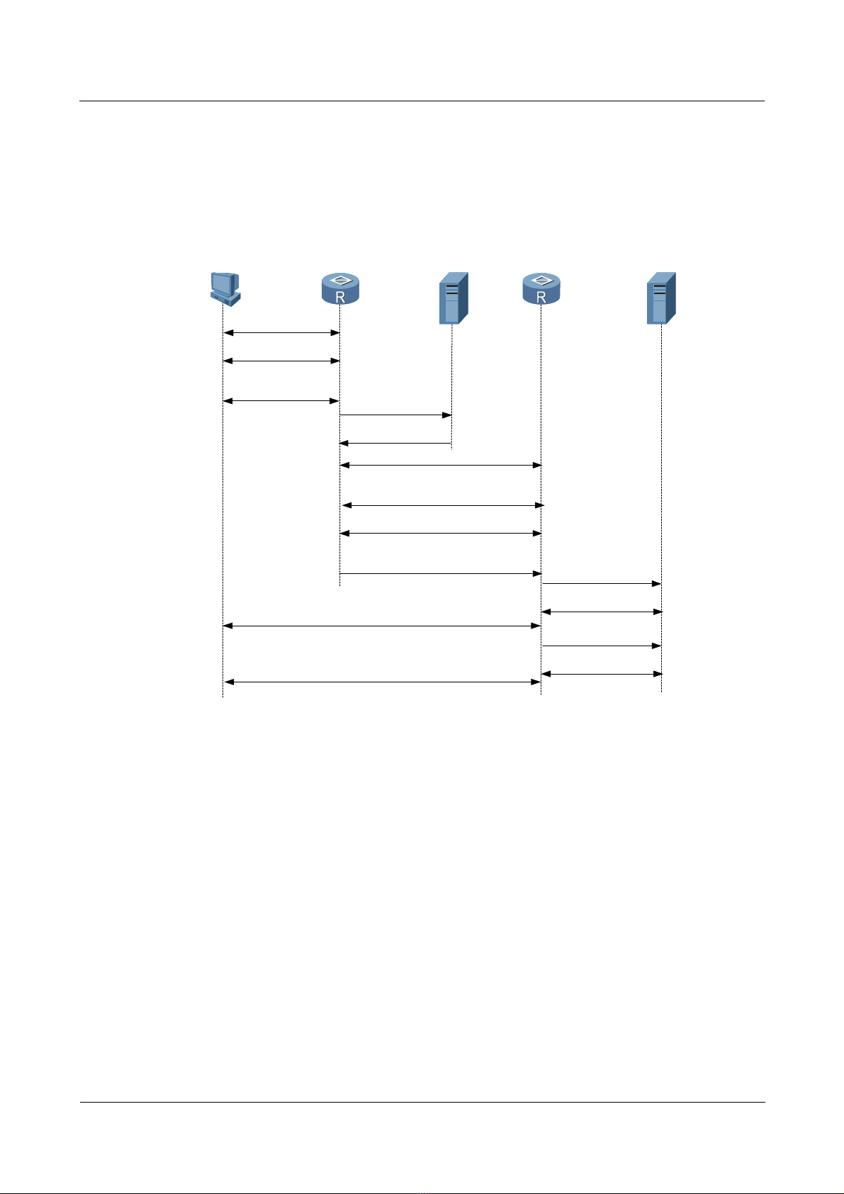
1.1.2 L2TP tunnel session setup
Figure 1-2 shows the process for setting up an L2TP tunnel.
Figure 1-2 The process flow for setting up an L2TP tunnel
PC
(1) call setup
(2) PPP LCP setup
(3) PAP or CHAP
authentication
(12) CHAP authentication twice(challenge/response)
LAC
RouterA
(4) access request
(5) access accept
(7) PAP or CHAP authent ication
(9) user CHAP response, PPP
RADIUS Server
(6) tunnel establish
(challenge/response)
(8) authentication pas ses
negotiation parameter
LAC
LNS
RouterB
(10) access request
(11) access accept
(13) access request
LNS
RADIUS Server
(15) authentication passes
(14) access accept
The procedure for setting up an L2TP tunnel is as follows:
1. The PC on the user side sends a connection request.
2. The PC and LAC device (Router A) negotiate the PPP LCP.
3. LAC carries out PAP or CHAP authentication based on the information from the PC.
4. LAC sends an access request with the VPN user name and password to the RADIUS
server for identity authentication.
5. The RADIUS server authenticates this user and sends an access accept message, such as
the LNS address. After the authentication succeeds, LAC is ready to start a new tunnel
request.
6. LAC makes a tunnel request to the LNS specified by the RADIUS server.
7. LAC informs LNS of a CHAP challenge, and LNS sends a CHAP response and its
CHAP challenge. LAC then sends back a CHAP response.
8. The authentication succeeds.
9. LAC transmits the information about the CHAP response, response identifier, and PPP
negotiation parameters to LNS.
Issue 5.3 (19 January 2009) Nortel Networks Inc. 1-3
Page 24
1 L2TP troubleshooting
10. LNS sends an access request to the RADIUS server for authentication.
11. The RADIUS server reauthenticates this access request and sends back a response if
authentication succeeds.
12. If local mandatory CHAP authentication is configured at LNS, LNS authenticates the
VPN user by sending a challenge. The VPN user at the PC side sends back a response.
13. LNS resends this access request to the RADIUS server for authentication.
14. The RADIUS server reauthenticates this access request and sends back a response if
authentication is successful.
15. After all authentications pass, the VPN user can use the internal resources of the
enterprise.
1.2 VPDN troubleshooting on the L2TP
The section describes the following topics:
z
Networking environment
z
Configuration notes
z
Diagnostic flowchart
z
Troubleshooting procedure
Nortel Secure Router 8000 Series
Troubleshooting - VPN
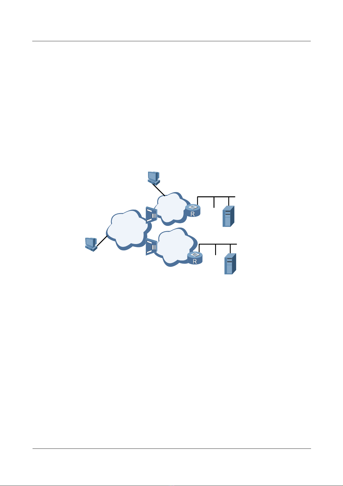
1.2.1 Networking environment
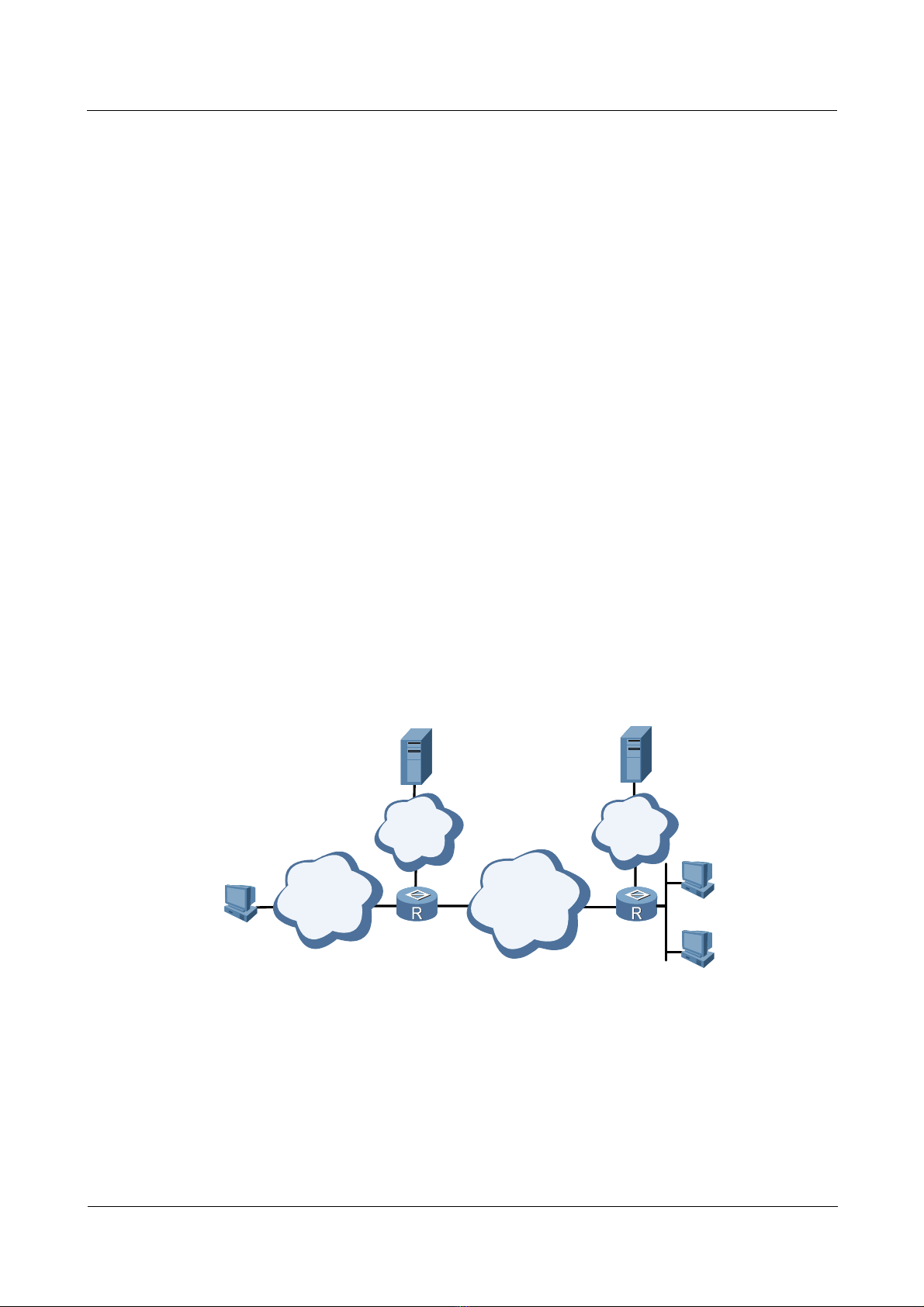
Figure 1-3 shows the networking of the L2TP tunnel.
Figure 1-3 Networking of the L2TP tunnel
RADIUS Server
IP
Network
PSTN/ISDN WAN
PC
RouterA
LAC LNS
RADIUS Server
IP
Network
PC
RouterB
PC
Router A works on the LAC side and Router B works on the LNS side. The user from the
LAC side sends the request for connection to the LNS side. This achieves the interconnection
with other PCs.
1-4 Nortel Networks Inc. Issue 5.3 (19 January 2009)
Page 25

Nortel Secure Router 8000 Series
Troubleshooting - VPN 1 L2TP troubleshooting
1.2.2 Configuration notes
Item Sub-item Description
Configuring
AAA
Configuring
VT
Configure the
authentication mode
Configure the domain
and the authenticatio n
mode
Configure the address
pool
Configure the user
name and password
Configure the PPP
authentication
To use the default local authentication, you
need to configure the user name and the
password in the AAA mode.
To use any other authentication, such as
RADIUS, you must configure the RADIUS
authentication.
You must configure the items for domain user
access.
Configure an address pool on the LNS side.
You need to configure common users to access
an address pool in the AAA mode and
configure domain users to access an address
pool in the domain mode.
The user names and passwords on the user side,
the LAC side, and the LNS side must be
consistent.
After the LCP renegotiation on the LNS side is
executed, you need to configure the PPP
authentication mode on the virtual interface
template. Otherwise, the user cannot pass the
authentication.
Configuring
L2TP
Appointment of the
address pool
Configure the MTU Nortel recommends that you configure the
Enable the L2TP Configure the L2TP only after the L2TP is
Source interface of the
tunnel on the LAC side
The name of the tunnel The name of the tunnel on the LAC side must
The authentication of
the tunnel
The password of the
authentication of the
tunnel
To configure an address pool for a user, the
number of address pool configured here must
be the same as that configured in the AAA
view.
MTU value as 1450.
enabled.
You can specify the loopback interface,
Ethernet interface, and GigabitEthernet
interface as the source interface of the tunnel.
be consistent with the name of the remote end
to receive the tunnel on the LNS side.
The configuration for tunnel authentication on
the LAC side must be the same as that on the
LNS side.
After tunnel authentication is enabled, the
passwords on both the LAC side and the LNS
side must be consistent.
Issue 5.3 (19 January 2009) Nortel Networks Inc. 1-5
Page 26

1 L2TP troubleshooting
Item Sub-item Description
Nortel Secure Router 8000 Series
Troubleshooting - VPN
The list separator of the
user postfix
The static route on the
LAC side
The request for the
connection with the
L2TP allowed on the
LNS side
The IP address of the
L2TP group bound on
the LNS side
The user authentication
on the LNS side
If you establish the connection with L2TP
through the domain, you need to run the l2tp
domain command to configure the separator of
the user postfix.
When the LNS side uses the IP address of the
loopback interface as the IP address of the
L2TP group, you must configure the route to be
reachable to the LNS loopback interface on the
LAC side.
If the number of the L2TP is 1, you need not
specify the remote-name. If you specify the
remote name in the L2TP group 1 view, L2TP
group 1 does not work as the default L2TP
group.
The IP address of the Ethernet interface,
GigabitEthernet interface, and loopback
interface can be used as the IP address of an
L2TP group. After the loopback interface is
bound, it cannot be used for other services.
After the LCP renegotiation is configured on
the LNS side, you need to configure the PPP
authentication mode on the correct virtual
interface template. Otherwise, the user cannot
pass the authentication.
Domain — Generally, bind VTs and configure address
pools in the domain view when L2TP users
access Layer 3 VPN groups. In other cases,
bind VTs in the L2TP group view.
As an example for the configuration notes for the L2TP LNS, consider users in different
domains that access the VPN.
1. Configure the interface of the LNS and LAC Ethernet2/0/0 and the address.
[Nortel] interface ethernet2/0/0
[Nortel-Ethernet2/0/0] ip address 10.1.1.3 255.255.255.0
[Nortel-Ethernet2/0/0] quit
2. Create a virtual template (VT) required by the L2TP group.
[Nortel] interface virtual-template 1
[Nortel-Virtual-Template1] ip address 35.1.1.1 255.255.255.0
[Nortel-Virtual-Template1] mtu 1450
[Nortel-Virtual-Template1] ppp authentication-mode pap
[Nortel-Virtual-Template1] quit
The VT executes the LCP and PAP negotiation with the user.
3. Configure the loopback interface required by the L2TP group.
[Nortel] interface LoopBack 0
1-6 Nortel Networks Inc. Issue 5.3 (19 January 2009)
Page 27

Nortel Secure Router 8000 Series
Troubleshooting - VPN 1 L2TP troubleshooting
[Nortel-LoopBack0] ip address 100.1.1.1 255.255.255.255
[Nortel-LoopBack0] quit
As the terminal IP of the tunnel, the interface is responsible for decompressing the L2TP
header and preparing for the next forwarding.
4. Configure the attributes on the L2TP group to be consistent with those on the LAC side.
# Enable the L2TP.
[Nortel] l2tp enable
# Set the identifier of the domain to be the @ symbol.
[Nortel] l2tp domain suffix-separator @
# Create the L2TP group.
[Nortel] l2tp-group 1
# Configure the name of the local tunnel as LNS.
[Nortel-l2tp1] tunnel name LNS
# Specify the VT to negotiate with the user, and the remote name (you do not need to
configure the remote name if the L2TP group number is 1).
[Nortel-l2tp1] allow l2tp virtual-template 1 remote LAC
# Configure the tunnel authentication to be consistent with the LAC.
[Nortel-l2tp1] tunnel authentication
# Configure the password of the tunnel to be the same as the LAC.
[Nortel-l2tp1] tunnel password simple 12345
# Configure the destination number of the tunnel to be loopback 0.
[Nortel-l2tp1] tunnel destination loopback 0
[Nortel-l2tp1] quit
5. Create a domain and bind the virtual template and the corresponding address pool in the
domain.
[Nortel] aaa
[Nortel-aaa] domain nortel1.com
[Nortel-aaa-domain-nortel1.com] ip pool 8 8.1.1.2 8.1.1.10
[Nortel-aaa-domain-nortel1.com] quit
[Nortel-aaa] domain nortel2.com
[Nortel-aaa-domain-nortel2.com] ip pool 9 9.1.1.2 9.1.1.10
[Nortel-aaa-domain-nortel2.com] quit
6. Create two user names and passwords.
[Nortel-aaa] local-user vpdn@nortel1.com password simple 11111
[Nortel-aaa] local-user vpdn@nortel2.com password simple 22222
1.2.3 Diagnostic flowchart
Figure 1-4 shows the flowchart for diagnosing faults on L2TP.
Issue 5.3 (19 January 2009) Nortel Networks Inc. 1-7
Page 28
1 L2TP troubleshooting
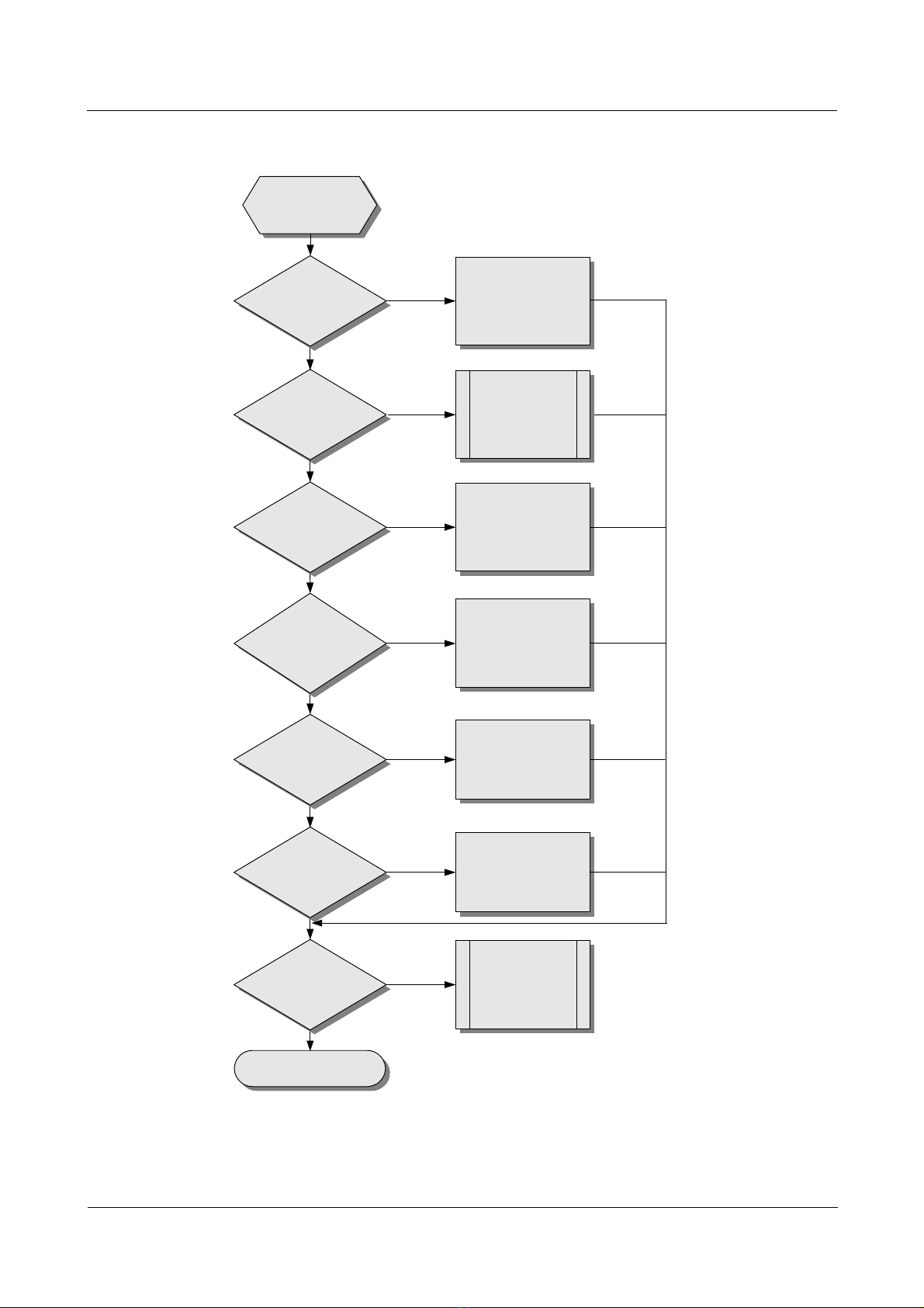
Figure 1-4 The flowchart for diagnosing faults on L2TP
Nortel Secure Router 8000 Series
Troubleshooting - VPN
Data cannot
be transmitte d.
Is the user
address correct?
Yes
Is the network
free of
congestion?
Yes
Does the tunnel
exist?
Yes
Is the
configuration of
PPP negotiation
on the LNS side
correct?
Yes
Can LAC
ping through the
LNS interface?
No
No
No
No
No
Configure the correct
user address.
Solve the
problem of the
network
congestion.
Check every
configuration and
establish the tunnel .
Reconfigure the
PPP parameters
on the LNS side.
Check the Loopback
interface bound by
the L2TP group of
the route and LNS.
Yes
Is the
PPP negotiation on
LAC normal?
Yes
Is the problem
solved?
Yes
End
No
No
Reconfigure the
PPP parameter
on the LAC side.
Seek the
technology
support.
1-8 Nortel Networks Inc. Issue 5.3 (19 January 2009)
Page 29

Nortel Secure Router 8000 Series
Troubleshooting - VPN 1 L2TP troubleshooting
1.2.4 Troubleshooting procedures
The troubleshooting procedures are as follows.
Step 1 Determining that the user address is correct
Step 2 Checking whether network congestion occurs
Step 3
Step 4 Checking the state of PPP negotiation on the LNS side
Step 5 Checking that the LAC can ping through the loopback interface of the LNS
Step 6 Checking the status of PPP negotiation on the LAC side
Checking that the tunnel exists
----End
The following sections describe the troubleshooting steps.
Determining that the user address is correct
The LNS can assign the address to the user, or the user can specify the address. If the assigned
address and the specified address are not in the same network segment, the data transmission
fails. Nortel recommends that the LNS assign the address. The two cases are as follows:
z
When the user accesses LNS with the full name, LNS checks that the correct address
pool is bound in the VT. You must configure the address pool in the AAA view correctly.
Run the remote address pool pool-number command to bind the address pool.
z
When the user accesses LNS with the domain name, LNS checks whether a correct
address pool is configured in the domain view. You can use the ip pool pool-number
first-address [ last-address ] command to configure the address pool in the domain view.
Then, use the remote address pool pool-num ber com mand in the VT interface view to
bind the address pool to this interface.
Checking whether network congestion occurs
L2TP transmits data based on the User Datagram Protocol (UDP). The UDP does not
implement error control on the packets. If you apply L2TP when the link is unstable, the data
transmission can fail.
Checking that the tunnel exists
You can use the display l2tp tunnel command to check whether the tunnel is established on
the LAC and LNC. If no corresponding tunnel exists, check the configuration using the
following methods:
1. Run the display this command in the L2TP group view on the LAC end to check
whether the LNS address with the start l2tp command is correctly configured. The
address should be the same as the loopback address on the LNS end. If they are different,
you need to reconfigure the LNS address.
2. Run the display this command in the L2TP group view on the LAC side to check
whether the LNS address is correct in the allow l2tp command. The address must be
consistent with the IP address of the loopback interface on the LNS end. If they are
inconsistent, you must reconfigure them.
Issue 5.3 (19 January 2009) Nortel Networks Inc. 1-9
Page 30

1 L2TP troubleshooting
3. Check whether the tunnel authentication and the password are correctly configured on
the LAC and LNS ends. The request for the tunnel authentication can be initiated from
either the LAC or the LNS. If one end starts the tunnel authentication, the tunnel can be
established only when the remote end also starts the tunnel authentication and the
passwords of both ends are consistent. Run the display this command in the L2TP group
view on the LAC and LNS sides to check if the passwords of the tunnels are consistent.
If one end is configured with the tunnel authentication but the passwords on both ends
are inconsistent, use the tunnel password { simple | cipher } password command to
configure the passwords.
4. Check whether the correct virtual template (VT) is bound on the LNS side.
5. If one end is forcibly disconnected, while the remote end does not receive the Disconnect
packet, the tunnel between the two ends cannot be connected. This is because the remote
end requires a period of time to test the disconnection of the link.
6. LNS does not accept the request for the connection of the tunnel from the LACs that
have the same IP addresses. If the two LACs simultaneously send the request for the
connection of the tunnel, the tunnel cannot be established.
Checking the state of PPP negotiation on the LNS side
1. Check that LCP renegotiation or forced CHAP authentication is configured.
Nortel Secure Router 8000 Series
Troubleshooting - VPN
Run the display this command in the L2TP group view to check if LCP renegotiation or
forced CHAP authentication is configured. When the device is connected with the LAC
equipment of other companies, the user authentication on the LNS uses the LCP
renegotiation. You can configure the LAC device according to actual requirements.
After you configure LCP renegotiation on the LNS side, you must configure PPP
authentication on the corresponding virtual interface template. Otherwise, the user cannot
pass the authentication.
2. Check that the LNS configures the corresponding user name and the password.
The two cases are as follows:
− For local authentication, check whether the correct user name and password are
configured in the AAA view. If they are incorrect, configure them by using the
local-user user-name password { simple | cipher } password command.
− For RADIUS authentication, see the section about VAS troubleshooting in Nortel
Secure Router 8000 Series Troubleshooting - VAS (NN46240-709).
3. Use the display ip pool command to check whether the address pool is small or no
address pool is configured.
4. Use the display this command in the VT view to check whether the authentication type
is consistent with that of the LAC.
Checking that the LAC can ping through the loopback interface of the LNS
1. Ping the loopback interface from the LAC. If you can ping through the loopback
interface, a reachable route between the LAC and LNS exists. If not, check whether the
static route of the loopback interface on the LNS has been configured by the display ip
routing-table command.
2. If a static route exists, you can use the display this command in the L2TP group view on
the LNS side to check that the L2TP group binds the loopback interface. If no loopback
interface is bound, use the tunnel destination loopback command to bind it.
1-10 Nortel Networks Inc. Issue 5.3 (19 January 2009)
Page 31

Nortel Secure Router 8000 Series
Troubleshooting - VPN 1 L2TP troubleshooting
Checking the status of PPP negotiation on the LAC side
The user needs to pass the PPP authentication on the LAC end before the L2TP tunnel and
session are established. The methods are as follows:
1. If the LAC end uses local authentication, you can use the local-user user-name
password { simple | cipher } password command in the AAA mode to check that the
correct user name and password are configured on the LAC end.
2. If the LAC end uses RADIUS authentication, see the section about VAS troubleshooting
in Nortel Secure Router 8000 Series Troubleshooting - VAS (NN46240-709).
3. If access with the full user name is used, you can use the display local-user command to
check that the corresponding user is configured and the user matches with the name of
the client. If not, modify the user name of either end. Use the start l2tp ip ip-address
fullusername user-name command to modify the user name on the LAC end.
4. If access with the domain name is used, check that the postfix of the domain name
matches the domain name of the end user, and check if the list separator of the domain
name postfix corresponding with the end user is configured. If they do not match, modify
the postfix of the domain name with the start l2tp ip ip-address domain domain-name
command. If no list separator of the domain name postfix exists, use the l2tp domain
suffix-separator command to configure it.
5. Check whether the PPP authentication mode configured on the user interface on the LAC
end is consistent with that on the LNS side. The command for PPP authentication is ppp
authentication { pap | chap }.
6. Check whether the authentication mode on the LAC end is consistent with that on the
user end. If not, modify the authentication end on one end. For example, the default
authentication mode of the VPN connection created by Wind ow s 2000 is MSCHAP . If
the LAC does not support MSCHAP, change the mode to CHAP.
If the preceding configurations are correct, the user can pass the authentication on the LAC
end. If you still cannot resolve the L2TP faults, contact Nortel technical support.
1.3 Troubleshooting L2TP access to the Layer 3 VPN
The section describes the following topics:
z
Networking environment
z
Configuration notes
z
Diagnostic flowchart
z
Troubleshooting procedure
1.3.1 Networking environment
If many enterprises use one LNS and users of an enterprise need to communicate with their
own headquarters, but the network address is a private IP address, for example 10.8.0.0, the
users cannot access the internal server of the enterprise through the Internet. To enable users
to access the internal network of the enterprise, you can establish a VPN that supports
multiple instances.
As shown in
PC1 is the user of the enterprise. The domain name of headquarters of the 02 enterprise is
163.net and PC2 is the user of the enterprise.
Figure 1-5, the domain name of headquarters of the 01 enterprise is 263.net and
Issue 5.3 (19 January 2009) Nortel Networks Inc. 1-11
Page 32

1 L2TP troubleshooting
Figure 1-5 Networking of the L2TP access to the Layer 3 VPN
Nortel Secure Router 8000 Series
Troubleshooting - VPN
Modem
PC1
PC2
PSTN
ISDN
1.3.2 Configuration notes
Item Sub-item Description
Configuring AAA
RouterA
LAC
Configure the
authentication mode
Headquarter
01
WAN
RouterB
tunnel
LNS
Headquarter
02
To use the default local authentication,
you need to configure the user name and
the password in the AAA mode.
To use any other authentication, such as
RADIUS, you must configure the
RADIUS authentication.
Configuring VT
Configure the domain
and the authenticatio n
mode
Configure the address
pool
Configure the user
name and password
Configure PPP
authentication
Assign the address
pool
You must configure the items for domain
user access.
Configure an address pool on the LNS
side. You need to configure common users
to access an address pool in the AAA
mode, and configure domain users to
access an address pool in the domain
mode.
The user names and passwords on the user
side, the LAC side, and the LNS side must
be consistent.
After the LCP renegotiation on the LNS
side is executed, you need to configure the
PPP authentication mode on the virtual
interface template. Otherwise, the user
cannot pass the authentication.
To configure an address pool for a user,
the number of address pool configured
here must be the same as that configured
in the AAA view.
Configure the MTU Nortel recommends that you configure the
MTU value to 1450.
1-12 Nortel Networks Inc. Issue 5.3 (19 January 2009)
Page 33

Nortel Secure Router 8000 Series
Troubleshooting - VPN 1 L2TP troubleshooting
Item Sub-item Description
Bind the VPN Bind the corresponding VPN in the VT
view.
Configuring L2TP
Enable L2TP L2TP can be configured only after L2TP
is enabled.
The source interface
of the tunnel on the
LAC side
You can specify the loopback interface,
Ethernet interface, and GigabitEthernet
interface as the source interface of the
tunnel.
The name of the
tunnel
The name of the tunnel on the LAC side
must be consistent with the name of the
remote end to receive the tunnel on the
LNS side.
The authentication of
the tunnel
The configuration for whether to enable
tunnel authentication on the LAC side
must be the same as that on the LNS side.
The password of the
authentication of the
tunnel
The list separator of
the user postfix
After tunnel authentication is enabled, the
passwords on both the LAC and LNS ends
must be consistent.
If you establish the connection with the
L2TP through the domain, you need to run
the l2tp domain command to configure
the separator of the user postfix.
The static route on the
LAC side
The request for the
connection with the
L2TP allowed on the
LNS side
The IP address of the
L2TP group bound on
the LNS side
The user
authentication on the
LNS side
When the LNS side uses the IP address of
the loopback interface as the IP address of
the L2TP group, you must configure the
route to be reachable to the LNS loopback
interface on the LAC side.
If the number of the L2TP group is 1, you
need not specify the remote name. If you
specify the remote name in the L2TP
group 1 view, the L2TP group 1 does not
work as the default L2TP group.
You can use the IP address of the Ethernet
interface, GigabitEthernet interface, and
loopback interface as the IP address of an
L2TP group. After the loopback interface
is bound, it cannot be used for other
services.
After LCP renegotiation is configured on
the LNS side, you need to configure the
PPP authentication mode on the
corresponding virtual interface template.
Otherwise, the user cannot pass the
authentication.
Issue 5.3 (19 January 2009) Nortel Networks Inc. 1-13
Page 34

1 L2TP troubleshooting
Item Sub-item Description
Domain — Generally, bind VTs and configure
Nortel Secure Router 8000 Series
Troubleshooting - VPN
address pools in the domain view when
L2TP users access Layer 3 VPN groups.
In other cases, bind VTs in the L2TP
group view.
VPN Configure the VPN
instances
Configure the VPN instances and then
associate them to the VT.
The following section describes the configuration based on the preceding networking
environment.
1. Configure the user side.
Establish a dial-up network. The number is the access number of the Nortel1 router. The
dial-up network receives the address assigned by the LNS server.
In PC1, enter the user name vpdn@263.net in the dial-up terminal window with the
password 11111. (The user name and the password must be r egistered in LNS.)
In PC2, enter the user name vpdn@163.net in the dial-up terminal window with the
password 22222. (The user name and the password must be registered in LNS.)
2. Configure the LAC side.
# Configure the user authentication on the LAC side.
# Configure the L2TP group and relative attributes.
# Start the tunnel authentication and configure the password of the tunnel authentication.
# Configure the separator of the domain name postfix.
# Configure the user name, the password, and the access domain name to be the same as
those on the client side.
3. Configure the LNS side.
# Configure the interface Ethernet2/0/0 of the LNS and LAC interfaces and configure the
address.
[Nortel] interface ethernet2/0/0
[Nortel-Ethernet2/0/0] ip address 10.1.1.3 255.255.255.0
[Nortel-Ethernet2/0/0] quit
# Create a virtual template for the L2TP group.
[Nortel] interface virtual-template 1
[Nortel-Virtual-Template1] ip address 35.1.1.1 255.255.255.0
[Nortel-Virtual-Template1] mtu 1450
[Nortel-Virtual-Template1] ppp authentication-mode pap
[Nortel-Virtual-Template1] quit
# Create a loopback interface for the L2TP group.
[Nortel] interface LoopBack 0
[Nortel-LoopBack0] ip address 100.1.1.1 255.255.255.255
[Nortel-LoopBack0] quit
# Create an L2TP group and configure its attributes (consistent with that on the LAC
side).
1-14 Nortel Networks Inc. Issue 5.3 (19 January 2009)
Page 35

Nortel Secure Router 8000 Series
Troubleshooting - VPN 1 L2TP troubleshooting
[Nortel] l2tp enable
[Nortel] l2tp domain suffix-separator @
[Nortel] l2tp-group 1
[Nortel-l2tp1] tunnel name LNS
[Nortel-l2tp1] allow l2tp virtual-template 1
[Nortel-l2tp1] tunnel authentication
[Nortel-l2tp1] tunnel password simple 12345
[Nortel-l2tp1] tunnel destination loopback 0
# When the Nortel LAC device is connected with the device of another company, the
user authentication on the LNS side uses LCP renegotiation. You can configure the
Nortel LAC device according to your actual requirements.
[Nortel-l2tp1] mandatory-lcp
[Nortel-l2tp1] quit
# Create two domains and configure the corresponding address pool in the domain.
[Nortel] aaa
[Nortel-aaa] domain 263.net
[Nortel-aaa-domain-263.net] binding virtual-template 8
[Nortel-aaa-domain-263.net] ip pool 8 8.1.1.2 8.1.1.10
[Nortel-aaa-domain-263.net] quit
[Nortel-aaa] domain 163.net
[Nortel-aaa-domain-163.net] binding virtual-template 9
[Nortel-aaa-domain-163.net] ip pool 9 9.1.1.2 9.1.1.10
[Nortel-aaa] quit
# Create two VPN instances.
[Nortel] ip vpn-instance vpn1
[Nortel–vpn-instance-vpn1] route-distinguisher 1:10
[Nortel–vpn-instance-vpn1] vpn-target 1:10 export-extcommunity
[Nortel–vpn-instance-vpn1] vpn-target 1:10 import-extcommunity
[Nortel–vpn-instance-vpn1] quit
[Nortel] ip vpn-instance vpn2
[Nortel–vpn-instance-vpn2] route-distinguisher 1:11
[Nortel–vpn-instance-vpn2] vpn-target 1:11 export-extcommunity
[Nortel–vpn-instance-vpn2] vpn-target 1:11 import-extcommunity
[Nortel-vpn-instance-vpn2] quit
# Create two corresponding virtual templates and bind them with VPN instances.
[Nortel] interface virtual-template 8
[Nortel-Virtual-Template8] ip binding vpn-instance vpn1
[Nortel-Virtual-Template8] ip address 8.1.1.1 255.255.255.0
[Nortel-Virtual-Template8] mtu 1450
[Nortel-Virtual-Template8] remote address pool 8
[Nortel-Virtual-Template8] ppp authentication-mode pap
[Nortel-Virtual-Template8] quit
[Nortel] interface virtual-template 9
[Nortel-Virtual-Template9] ip binding vpn-instance vpn2
[Nortel-Virtual-Template9] ip address 9.1.1.1 255.255.255.0
[Nortel-Virtual-Template9] mtu 1450
[Nortel-Virtual-Template9] remote address pool 9
[Nortel-Virtual-Template9] ppp authentication pap
[Nortel-Virtual-Template9] quit
Issue 5.3 (19 January 2009) Nortel Networks Inc. 1-15
Page 36

1 L2TP troubleshooting
# Create two user names and passwords.
[Nortel-aaa] local-user vpdn@263.net password simple 11111
[Nortel-aaa] local-user vpdn@163.net password simple 22222
In the preceding configuration, you need to modify the AAA configuration if the LNS end
uses RADIUS authentication.
1.3.3 Diagnostic flowchart
The diagnostic flowchart is the same as the flowchart shown in Figure 1-4.
1.3.4 Troubleshooting procedure
The troubleshooting procedure is as follows:
Nortel Secure Router 8000 Series
Troubleshooting - VPN
Step 1 Check faults by using the steps in “
VPDN troubleshooting on the L2TP.”
Step 2 Check that the correct VPN instances are bound on the VT on the LNS side.
Step 3 Check that the correct VT is bound in the AAA domain.
----End
1.4 Troubleshooting cases
1.4.1 The session disconnects as soon as it is set up
Networking environment
Figure 1-6 Netw orking of the disc onnectio n of the L 2TP session
Modem
PC1
PSTN
RouterA
WAN
RouterB
Tunnel
LNS
Server
headquarter
PC2
ISDN
LAC
Fault symptom
The sessions on both the LAC and LNS sides disconnect as soon as they are set up.
1-16 Nortel Networks Inc. Issue 5.3 (19 January 2009)
Page 37

Nortel Secure Router 8000 Series
Troubleshooting - VPN 1 L2TP troubleshooting
Fault analysis
The establishment of the session indicates that LAC and LNS are reachable. It also indicates
that the request for the connection with the L2TP is initiated. Faults on the LNS may cause the
disconnection of the session.
Enable debugging of the L2TP control on the LNS. By verifying the debugging information,
you can determine whether the session is disconnected when the interface receives the Call
Down message.
When you enable debugging of PPP on the LNS by using the debugging ppp all command,
you can find abnormalities.
*0.2426289 Nortel PPP/8/debug2:Slot=1;
PPP Event:
Virtual-Template1:0 : Ask AAA peer's IP address
*0.2426417 Nortel PPP/8/debug2:Slot=1;
PPP Event:
Virtual-Template1:0 : WaitPeerIP Timer starting
*0.2426545 Nortel PPP/8/debug2:Slot=1;
PPP Event:
Virtual-Template1:0 : Receive Peer's IP address 0.0.0.0 from AAA
*0.2426705 Nortel PPP/8/debug2:Slot=1;
PPP Event:
Virtual-Template1:0 : WaitPeerIP Timer finished
*0.2426833 Nortel PPP/8/debug2:Slot=1;
The preceding information shows that the interface receives the IP address 0.0.0.0. To check
the configuration, see the procedure in the section “
can find that the access user is the domain user and no configured address pool is in the
domain. Although the VT is bound with the address pool, the domain user applies for the IP
address from the address pool in the domain. So, when the application for the address and the
IPCP negotiation of the PPP fail, the session is disconnected.
Troubleshooting procedure
Step 1 View the L2TP debugging information to determine that the interface receives the Call Down
information.
Step 2 Viewing the PPP debugging information to determine that the interface does not apply for an
IP address.
Step 3 Based on the configuration in the debugging information, you can find that no address pool is
configured in the domain.
----End
Summary
The cause is a configuration error. To resolve the problem, you need to understand the
differences between common user access and domain user access.
VPDN troubleshooting on the L2TP.” You
Issue 5.3 (19 January 2009) Nortel Networks Inc. 1-17
Page 38

1 L2TP troubleshooting
1.5 FAQs
Nortel Secure Router 8000 Series
Troubleshooting - VPN
z
Q: Why is the interface on the LAC side unable to ping through the loopback
interface of the LNS?
A: A possible cause is that the LAC has no route to the loopback interface of the LNS.
z
Q: Why is the PPP negotiation between the user and the LAC unsuccessful?
A: A possible cause is that the authentication modes configured on the user and the LAC
are different (one is PAP and the other is CHAP).
z
Q: Why is the PPP negotiation between the user and the LNS unsuccessful?
A: The possible causes are as follows.
− The configured address pool on the LNS end is too small or no address pool is
configured on the LNS end.
− No corresponding user is configured on the LNS end.
− The authentication of the tunnel between the LNS end and LAC does not pass.
− The authentication of the VT and the user are different.
− The IP address assigned by the LNS to the user conflicts with other addresses of the
user.
z
Q: The data cannot be transmitted although the connection is established. Why
does this occur?
A: The possible causes are as follows.
− Either the Forward Information Base (FIB) entry of the loopback interface on the
LNS has no decapsulation mark or the FIB entry of the user route on the LNS has no
encapsulation mark.
− Either network congestion or instability of the network quality occurs.
− The user end is configured with the IP address, but the IP address is not in the same
network segment as the VT.
z
Q: What are the differences between agent authentication, enforced CHAP
authentication, and LCP renegotiation?
A: The LCP renegotiation has the highest authority. That is, if you configure the LCP
renegotiation and the enforced CHAP authentication at the same time, the L2TP uses the
LCP renegotiation in the mode configured on the VT.
The enforced CHAP authentication has the secondary priority. That is, if you configure
only the enforced CHAP authentication without the LCP renegotiation, the LNS end
authenticates the user in CHAP mode. If the authentication does not pass, the session
cannot be established.
The agent authentication has the lowest authority. That is, if you do not configure the
enforced CHAP authentication or the LCP renegotiation, the LNS uses the agent
authentication. With agent authentication, the LAC transmits all authentication
information it gets from the users and the authentication mode configured on the LAC
end to the LNS. The LNS authenticates the users by the information and the
authentication mode transmitted from the LAC end.
The relationship between agent authentication and the authentication mode configured
on the VT are is follows:
− If you configure PAP authentication mode on LAC, while the authentication mode
configured on the VT on LNS is CHAP, the LAC cannot pass authentication because
the priority of CHAP on the LNS is higher.
1-18 Nortel Networks Inc. Issue 5.3 (19 January 2009)
Page 39

Nortel Secure Router 8000 Series
Troubleshooting - VPN 1 L2TP troubleshooting
− In other cases, the authentication mode sent by the LAC is used regardless of the type
of authentication mode configured on the VT.
When the LCP is configured for renegotiation and no authentication is configured on the
VT, the user is authenticated once. In other cases, the user is authenticated twice.
z
Q: What is the process of the L2TP tunnel authentication?
A: If two ends are configured with tunnel authentication, the L2TP tunnel authentication
process is as follows. The tunnel authentication and the tunnel establishment are
performed simultaneously.
− When the LAC sends the request for SCCRQ to the LNS, a random character string is
generated and sent to the LNS as the local CHAP challenge.
− After the LNS receives the challenge, it generates a new character string by adding
the locally configured password and SCCRP to the random character string,
determines a 16-byte response by MD5, and sends the response in the SCCRP
message with one random character string LNS Challenge to the LAC.
− The LAC adds the locally configured password and the SCCRP to its CHAP
challenge to generate a new character string. The LAC determines a 16-byte character
string by MD5. The LAC compares the 16-byte character string with the LNS CHAP
response received from the SCCRP. If they are identical, the LNS passes the
authentication. Otherwise, the tunnel is disconnected.
− The LNS authenticates the LAC in the same way: After the LAC finds the LNS
CHAP challenge in the SCCRP, it adds the local password and the SCCN to the
character string to generate a new character string. The LAC determines a 16-byte
character string by MD5 and sends it, as the LAC CHAP response, to the LNS in the
SCCCN message.
− After the LNS receives the SCCCN message, it adds the local password and the
SCCCN to the local CHAP challenge to make a character string. Then the LNS
determines a 16-byte character string by MD5 and compares it with the LAC CHAP
response received from the SCCCN message. If they are identical, the LAC passes
the authentication; if not, the tunnel is disconnected.
z
Q: Are there special considerations if the LNS end is a Nortel router and the LAC
end is not?
A: It is possible that the LNS end does not support certain parameters that are obtained
through PPP prenegotiation between the LAC end and the client end, so the PPP session
on the LNS end cannot be established. You need to configure the parameters of the PPP
renegotiation on the LNS end and force the LNS and the client end to perform the PPP
negotiation.
z
Q: Are there special considerations if the LAC end is a Nortel router and the LNS
end is not?
A: It is possible that the LAC end does not support certain parameters that are obtained
through PPP prenegotiation between the LNS end and the client end, so the PPP session
on the LAC end cannot be established. During configuration, examine the parameters of
the negotiation between the LNS end and the client end and ensure that these parameters
are supported.
Issue 5.3 (19 January 2009) Nortel Networks Inc. 1-19
Page 40

1 L2TP troubleshooting
1.6 Diagnostic tools
1.6.1 Display commands
Command Description
Nortel Secure Router 8000 Series
Troubleshooting - VPN
display l2tp tunnel
display l2tp session
display access-user
display current-configuration
configuration | include l2tp
display current-configuration
configuration aaa
display current-configuration
interface
display l2tp tunnel
<Nortel> display l2tp tunnel
Total tunnel = 1
LocalTID RemoteTID RemoteAddress Port Sessions RemoteName
2 22849 11.1.1.1 1701 1 lns
Table 1-1 Description of the output of the display L2tp tunnel command
Displays the L2TP tunnel.
Displays the L2TP session.
Displays the access user.
Displays the current L2TP configuration.
Displays the current AAA configuration.
Displays the current interface configuration.
Item Description
Total tunnel The number of tunnels
LocalTID The ID of the local tunnel
RemoteTID The ID of the remote tunnel
RemoteAddress The remote IP address
Port The number of the remote interface
Sessions The number of sessions on the tunnel
Remote Name The name of the remote end
display l2tp session
<Nortel> display l2tp session
LocalSID RemoteSID LocalTID
1 1 2
Total session = 1
1-20 Nortel Networks Inc. Issue 5.3 (19 January 2009)
Page 41

Nortel Secure Router 8000 Series
Troubleshooting - VPN 1 L2TP troubleshooting
Table 1-2 Description of the output of the display L2tp session command
Item Description
Total session The number of sessions
LocalSID The ID of the local session (the only identifier
of the session)
RemoteSID The ID of the remote session (the only
identifier of the session)
LocalTID The number of the local identifier
display access-user
# Check the information about the access user.
<Nortel> display access-user
--------------------------------------------------------------------------Total
users : 1
Wait authen-ack : 0
Authentication success : 1
Accounting ready : 1
Accounting state : 0
Wait leaving-flow-query : 0
Wait accounting-start : 0
Wait accounting-stop : 0
Wait authorization-client : 0
Wait authorization-server : 0
------------------------------------------------------------------ Domain-name Online-user
------------------------------------------------------------------ default : 0
home : 1
------------------------------------------------------------------ The used CID table are :5
---------------------------------------------------------------------
The preceding information indicates that one access user belongs to the home domain and its
ID is 5.
# Check the information about the access user (specify the ID of the user).
<Nortel-aaa> display access-user user-id 5
------------------------------------------------------------------ User access index : 5
State : Used
User name : vpdnuser@nortel.com
User access VLAN/PVC : 0
User MAC : ffff-ffff-ffff
User IP address : 120.1.1.11
Vpn-Instance : Public
User access type : PPP
User authentication type : PPP authentication
Current authen method : Local authentication
Issue 5.3 (19 January 2009) Nortel Networks Inc. 1-21
Page 42

1 L2TP troubleshooting
Authen result : Success
Current author method : Local authorization
Author result : Success
Action flag : Idle
Authen state : Authed
Author state : Idle
Accounting method : No accounting
Accounting start time : 2005-11-25 09:04:45
Accounting state : Ready
ACL-number : Priority : Up CAR enable : NO
Up average rate : 0(bps)
Up peak rate : 0(bps)
Down CAR enable : NO
Down average rate : 0(bps)
Down peak rate : 0(bps)
Up packets number(high,low) : (0,20)
Up bytes number(high,low) : (0,2360)
Down packets number(high,low) : (0,20)
Down bytes number(high,low) : (0,1120)
-------------------------------------------------------------------
Nortel Secure Router 8000 Series
Troubleshooting - VPN
The preceding information shows detailed information about the user with the ID 5, including
the user name, the IP address, the AAA, the online time, and the traffic.
display current-configuration configuration | include l2tp
# Check the current L2TP configuration.
<Nortel> display current-configuration configuration | include l2tp
#
L2tp enable
#
l2tp-group 1
undo tunnel authentication
allow l2tp virtual-template 1
tunnel name lns
#
return
display current-configuration configuration aaa
# Check the current AAA configuration.
<Nortel> display current-configuration configuration aaa
#
aaa
local-user vpdnuser@nortel.com password simple nortel
ip pool 1 120.1.1.2 120.1.1.10
#
authentication-scheme default
#
authorization-scheme default
#
accounting-scheme default
1-22 Nortel Networks Inc. Issue 5.3 (19 January 2009)
Page 43

Nortel Secure Router 8000 Series
Troubleshooting - VPN 1 L2TP troubleshooting
#
domain default
domain home
ip pool 2 120.1.1.11 120.1.1.20
#
#
return
display current-configuration interface
# Check the current interface configuration.
<Nortel> display current-configuration interface
#
interface Pos1/0/0
clock master
link-protocol ppp
ip address 31.1.1.2 255.255.0.0
#
interface Virtual-Template1
ip address 120.1.1.1 255.255.0.0
# interface Pos1/0/0
ip address 19.60.1.12 255.0.0.0
#
return
1.6.2 Debugging commands
Command Description
debugging l2tp all
debugging l2tp control
debugging l2tp dump
debugging l2tp error
debugging l2tp event
debugging l2tp hidden
debugging l2tp payload
debugging l2tp timestamp
debugging ppp all
Enables debugging of L2TP.
Enables debugging of the L2TP control packet.
Enables debugging of the L2TP PPP packet.
Enables debugging of L2TP errors.
Enables debugging of L2TP events.
Enables debugging of the Attribute Value Pair (AVP)
hidden by the L2TP.
Enables debugging of the L2TP data packet.
Enables debugging of the timestamp displayed by the
L2TP.
Checks the PPP debugging information about the
domain user access to the LNS end.
Example of L2TP debugging of the domain user access to the LNS end
<Nortel> debugging l2tp control
*0.2679317 Nortel L2TP/8/L2TDBG:Slot=1; L2TP::Recv mbuf vrfindex is 0
Issue 5.3 (19 January 2009) Nortel Networks Inc. 1-23
Page 44

1 L2TP troubleshooting
*0.2679393 Nortel L2TP/8/L2TDBG: L2TP::Proc Peer control type=1, len = 75
*0.2679473 Nortel L2TP/8/L2TDBG: L2TP::Tunnel 1 rcv SCCRQ in state 1 from 31.1.1.1
*0.2679569 Nortel L2TP/8/L2TDBG: L2TP::Tunnel 1 rcv SCCRQ fill vpn-index 0
*0.2679649 Nortel L2TP/8/L2TDBG: L2TP::Check SCCRQ MSG Type 1
*0.2679729 Nortel L2TP/8/L2TDBG: L2TP::Parse AVP Protocol version: 100
*0.2679809 Nortel L2TP/8/L2TDBG: L2TP::Parse AVP Host name, value: lac
*0.2679889 Nortel L2TP/8/L2TDBG: L2TP::Tunnel Password in l2tp Group:
*0.2679969 Nortel L2TP/8/L2TDBG: L2TP::Parse AVP Vendor name, value: Nortel
*0.2680049 Nortel L2TP/8/L2TDBG: L2TP::Parse AVP Framing capability : 3
*0.2680129 Nortel L2TP/8/L2TDBG: L2TP::Parse AVP Remote call number, value: 1
*0.2680225 Nortel L2TP/8/L2TDBG: L2TP::Parse AVP Receive window size, value: 128
*0.2680321 Nortel L2TP/8/L2TDBG: L2TP::Put AVP Message Type:
START_CONTROL_CONNECTION_REPLY
*0.2680417 Nortel L2TP/8/L2TDBG: L2TP::Put AVP Protocol version: 100
*0.2680497 Nortel L2TP/8/L2TDBG: L2TP::Put AVP Framing capability :3
*0.2680577 Nortel L2TP/8/L2TDBG: L2TP::Put AVP Host name: lns
*0.2680657 Nortel L2TP/8/L2TDBG: L2TP::Put AVP Assigned Tunnel ID: 1
*0.2680737 Nortel L2TP/8/L2TDBG: L2TP::Put AVP Bearer capability: 3
*0.2680817 Nortel L2TP/8/L2TDBG: L2TP::Put AVP Receive window size: 128
*0.2680897 Nortel L2TP/8/L2TDBG: L2TP:: O Tunnel 1 send START_CONTROL_CONNECTION_REPLY
to Tunnel 1
*0.2681025 Nortel L2TP/8/L2TDBG: L2TP::Tunnel 1 Create 60 seconds Hello timer
*0.2681121 Nortel L2TP/8/L2TDBG:Slot=1; L2TP::Recv mbuf vrfindex is 0
*0.2681201 Nortel L2TP/8/L2TDBG:Slot=1; L2TP::Recv mbuf vrfindex is 0
*0.2681281 Nortel L2TP/8/L2TDBG: L2TP::Proc Peer control type=3, len = 20
*0.2681361 Nortel L2TP/8/L2TDBG: L2TP::Tunnel 1 rcv SCCCN in state 3
*0.2681441 Nortel L2TP/8/L2TDBG: L2TP::Tunnel 1 Resume 60 second Hello timer
*0.2681521 Nortel L2TP/8/L2TDBG: L2TP::Check SCCCN MSG Type 3
*0.2681601 Nortel L2TP/8/L2TDBG: L2TP::Tunnel 1 Start Waiting Calls
*0.2681681 Nortel L2TP/8/L2TDBG: L2TP::Proc Peer control type=10, len = 68
*0.2681761 Nortel L2TP/8/L2TDBG: L2TP::Call 7834 recv ICRQ in state 2 from Call 0
*0.2681857 Nortel L2TP/8/L2TDBG: L2TP::Tunnel 1 Resume 60 second Hello timer
*0.2681937 Nortel L2TP/8/L2TDBG: L2TP::Check ICRQ MSG Type 10
*0.2682017 Nortel L2TP/8/L2TDBG: L2TP::Parse AVP Remote call ID 7256
*0.2682097 Nortel L2TP/8/L2TDBG: L2TP::Parse AVP Call serial number: 7256
*0.2682177 Nortel L2TP/8/L2TDBG: L2TP::Parse AVP Bearer type: 3
*0.2682257 Nortel L2TP/8/L2TDBG: L2TP::Parse AVP Physical channel ID:0
*0.2682337 Nortel L2TP/8/L2TDBG: L2TP::Parse AVP Dialed number: 8888
*0.2682417 Nortel L2TP/8/L2TDBG: L2TP::Put AVP Message Type: INCOMING_CALL_REPLY
*0.2682513 Nortel L2TP/8/L2TDBG: L2TP::Put AVP Assigned call ID: 7834
*0.2682593 Nortel L2TP/8/L2TDBG: L2TP::Call 7834 send INCOMING_CALL_REPLY to Remote Call
7256
*0.2682721 Nortel L2TP/8/L2TDBG:Slot=1; L2TP::Recv mbuf vrfindex is 0
*0.2682801 Nortel L2TP/8/L2TDBG: L2TP::Proc Peer control type=12, len = 139
*0.2682882 Nortel L2TP/8/L2TDBG: L2TP::Call 7834 rcv ICCN in state 5 from Remote Call
7256
*0.2682977 Nortel L2TP/8/L2TDBG: L2TP::Tunnel 1 Resume 60 second Hello timer
*0.2683057 Nortel L2TP/8/L2TDBG: L2TP::Check ICCN MSG Type 12
*0.2683137 Nortel L2TP/8/L2TDBG: L2TP::Parse AVP Tx connect speed: 64000
*0.2683217 Nortel L2TP/8/L2TDBG: L2TP::Parse AVP Framing type: 3
*0.2683297 Nortel L2TP/8/L2TDBG: L2TP::Parse AVP Initial recv lcp configure request:
5 6 20 E3 DA 8F
*0.2683425 Nortel L2TP/8/L2TDBG: L2TP::Parse AVP Last sent lcp configure request: 3 4
C0 23 5 6 0 25 E8 7F
Nortel Secure Router 8000 Series
Troubleshooting - VPN
1-24 Nortel Networks Inc. Issue 5.3 (19 January 2009)
Page 45

Nortel Secure Router 8000 Series
Troubleshooting - VPN 1 L2TP troubleshooting
*0.2683553 Nortel L2TP/8/L2TDBG: L2TP::Parse AVP Last received lcp configure request:
5 6 20 E3 DA 8F
*0.2683681 Nortel L2TP/8/L2TDBG: L2TP::Parse AVP Proxy authenticate type 3.
*0.2683761 Nortel L2TP/8/L2TDBG: L2TP::Parse AVP Proxy authenticate name:yyh@home.
*0.2683857 Nortel L2TP/8/L2TDBG: L2TP::Parse AVP Proxy authentication ID: 40435440.
*0.2683953 Nortel L2TP/8/L2TDBG: L2TP::Parse AVP Proxy authenticate response:31 32 33
*0.2684049 Nortel L2TP/8/L2TDBG: L2TP::Parse AVP Private group ID
*0.2684129 Nortel L2TP/8/L2TDBG: L2TP::Parse AVP (Rx)connect speed 64000
*0.2684209 Nortel L2TP/8/L2TDBG: L2TP::Call 7834 established , Send Call Struct to IO
slot 1
*0.2684305 Nortel L2TP/8/L2TDBG:Slot=1; L2TP::IPC Recv Src IPC ID=11 Dst node=7 Dst IPC
ID=11 Len=172
*0.2684433 Nortel L2TP/8/L2TDBG:Slot=1; L2TP::IPC rec data type=100 len=172
*0.2684513 Nortel L2TP/8/L2TDBG:Slot=1; L2TP::IPC Proc IPC data result 0
*0.2684609 Nortel L2TP/8/L2TDBG:Slot=1; L2TP::IO: Proc ctrl L2TP_INCALL_ESTABLISHED
from main
*0.2684721 Nortel L2TP/8/L2TDBG:Slot=1; L2TP::IO:: rec main establish call ID 7834 group
1 VT 1
*0.2684833 Nortel L2TP/8/L2TDBG: L2TP::IPC Recv Src IPC ID=11 Dst node=1 Dst IPC ID=11
Len=16
*0.2684945 Nortel L2TP/8/L2TDBG: L2TP::IPC rec data type=16 len=16
*0.2685025 Nortel L2TP/8/L2TDBG: L2TP::IPC Proc IPC data result 0
*0.2685105 Nortel L2TP/8/L2TDBG: L2TP::Put AVP Message Type: SET_LINK_INFO
*0.2685185 Nortel L2TP/8/L2TDBG: L2TP::Put AVP ACCM: 0 0
*0.2685249 Nortel L2TP/8/L2TDBG: L2TP:: O Call 7834 send SLI
*0.2685313 Nortel L2TP/8/L2TDBG:Slot=1; L2TP::IPC Recv Src IPC ID=11 Dst node=7 Dst IPC
ID=11 Len=1384
*0.2685441 Nortel L2TP/8/L2TDBG:Slot=1; L2TP::IPC rec data type=100 len=1384
*0.2685521 Nortel L2TP/8/L2TDBG:Slot=1; L2TP::IPC Proc IPC data result 0
*0.2685601 Nortel L2TP/8/L2TDBG:Slot=1; L2TP::IO: Proc ctrl L2TP_PHY_READY from main
*0.2685697 Nortel L2TP/8/L2TDBG:Slot=1; L2TP::LNS Virtual Access for Call :7834 UP
*0.2685793 Nortel L2TP/8/L2TDBG:Slot=1; L2TP::LNS Link IO Ctrl Recv Phy CMD 23
*0.2685889 Nortel L2TP/8/L2TDBG:Slot=1; L2TP::LNS Link IO Ctrl Recv Phy CMD 24
*0.2685985 Nortel L2TP/8/L2TDBG:Slot=1; L2TP::LNS Link IO Ctrl Recv Phy CMD 41
*0.2686081 Nortel L2TP/8/L2TDBG:Slot=1; L2TP::Send ACCM. CALL = 7834
*0.2686161 Nortel L2TP/8/L2TDBG:Slot=1; L2TP::IPC sent ctrl L2TP_INCALL_ESTABLISHED
len=16 result=0 to main
*0.2686289 Nortel L2TP/8/L2TDBG:Slot=1; L2TP::Recv mbuf vrfindex is 0
*0.2686369 Nortel L2TP/8/L2TDBG: L2TP::Proc Peer control len = 12
*0.2699426 Nortel L2TP/8/L2TDBG:Slot=1; L2TP::LNS Link IO Ctrl Recv Phy CMD 36
*0.2699521 Nortel L2TP/8/L2TDBG: L2TP::IPC Recv Src IPC ID=11 Dst node=1 Dst IPC ID=11
Len=16
*0.2699633 Nortel L2TP/8/L2TDBG: L2TP::IPC rec data type=4 len=16
*0.2699713 Nortel L2TP/8/L2TDBG: L2TP::IPC Proc IPC data result 0
*0.2699793 Nortel L2TP/8/L2TDBG: L2TP::Proc Call Down , Call in State 9
*0.2699873 Nortel L2TP/8/L2TDBG: L2TP::Put AVP Message Type: CALL_DISCONNECT_NOTIFY
*0.2699969 Nortel L2TP/8/L2TDBG: L2TP::Put AVP Result code: LOSS_OF_CARRIER
*0.2700049 Nortel L2TP/8/L2TDBG: L2TP::Put AVP Assigned call ID: 7834
*0.2700129 Nortel L2TP/8/L2TDBG: L2TP:: O Call 7834 send CALL_DISCONNECT_NOTIFY
*0.2700225 Nortel L2TP/8/L2TDBG: L2TP::Clean Call Structure ID = 7834
*0.2700305 Nortel L2TP/8/L2TDBG:Slot=1; L2TP::IPC Recv Src IPC ID=11 Dst node=7 Dst IPC
ID=11 Len=32
*0.2700417 Nortel L2TP/8/L2TDBG:Slot=1; L2TP::IPC rec data type=100 len=32
*0.2700497 Nortel L2TP/8/L2TDBG:Slot=1; L2TP::IPC Proc IPC data result 0
Issue 5.3 (19 January 2009) Nortel Networks Inc. 1-25
Page 46

Nortel Secure Router 8000 Series
1 L2TP troubleshooting
*0.2700577 Nortel L2TP/8/L2TDBG:Slot=1; L2TP::IPC sent ctrl L2tp down to main len=16
result=0 to main
*0.2700705 Nortel L2TP/8/L2TDBG:Slot=1; L2TP::IO: Proc ctrl L2TP_LNSINCALL_CLEAR from
main
*0.2700801 Nortel L2TP/8/L2TDBG:Slot=1; L2TP::Call 7834 Proc main call clear
*0.2700881 Nortel L2TP/8/L2TDBG:Slot=1; L2TP::LNS Link IO Ctrl Recv Phy CMD 2
*0.2700977 Nortel L2TP/8/L2TDBG:Slot=1; L2TP::LNS Link IO Ctrl Recv Phy CMD 11
*0.2701073 Nortel L2TP/8/L2TDBG:Slot=1; L2TP::IO:: Call clear 7834
*0.2701153 Nortel L2TP/8/L2TDBG:Slot=1; L2TP::Recv mbuf vrfindex is 0
*0.2701248 Nortel L2TP/8/L2TDBG: L2TP::Proc Peer control len = 12
Troubleshooting - VPN
Example of PPP debugging of the domain user access to the LNS end
<Nortel> debugging ppp all
*0.2347645 Nortel PPP/8/debug2:Slot=1;
PPP State Change:
Virtual-Template1:0 LCP : initial --> reqsent
*0.2347761 Nortel PPP/8/debug2:Slot=1;
PPP State Change:
Virtual-Template1:0 LCP : reqsent --> ackrcvd
*0.2347889 Nortel PPP/8/debug2:Slot=1;
PPP State Change:
Virtual-Template1:0 LCP : ackrcvd --> opened
*0.2348017 Nortel PPP/8/debug2:Slot=1;
PPP Event:
Virtual-Template1:0 : PPP Notify low layer to send remote accm 0 , local
accm 0 Packet
*0.2348193 Nortel PPP/8/debug2:Slot=1;
PPP Event:
Virtual-Template1:0 PAP Initial Event
state Initial
*0.2348337 Nortel PPP/8/debug2:Slot=1;
PPP Event:
Virtual-Template1:0 PAP AAA Result Event
state WaitAAA
*0.2348481 Nortel PPP/8/debug2:Slot=1;
PPP Packet:
Virtual-Template1:0 Output PAP(c023) Pkt, Len 52
State WaitAAA, code Ack(02), id 0, len 48
Msg Len: 43 Msg:Welcome to use Nortel ROUTER, Nortel Tech.
*0.2348769 Nortel PPP/8/debug2:Slot=1;
PPP State Change:
Virtual-Template1:0 PAP : WaitAAA --> ServerSuccess
*0.2348913 Nortel PPP/8/debug2:Slot=1;
PPP Event:
Virtual-Template1:0 : Ask AAA peer's IP address
*0.2349041 Nortel PPP/8/debug2:Slot=1;
PPP Event:
Virtual-Template1:0 : WaitPeerIP Timer starting
*0.2349169 Nortel PPP/8/debug2:Slot=1;
PPP Event:
Virtual-Template1:0 : Receive Peer's IP address 120.1.1.11 from AAA
*0.2349329 Nortel PPP/8/debug2:Slot=1;
PPP Event:
Virtual-Template1:0 : WaitPeerIP Timer finished
*0.2349457 Nortel PPP/8/debug2:Slot=1;
1-26 Nortel Networks Inc. Issue 5.3 (19 January 2009)
Page 47

Nortel Secure Router 8000 Series
Troubleshooting - VPN 1 L2TP troubleshooting
PPP Event:
Virtual-Template1:0 IPCP Open Event
state initial
*0.2349601 Nortel PPP/8/debug2:Slot=1;
PPP State Change:
Virtual-Template1:0 IPCP : initial --> starting
*0.2349729 Nortel PPP/8/debug2:Slot=1;
PPP Event:
Virtual-Template1:0 IPCP Lower Up Event
state starting
*0.2349889 Nortel PPP/8/debug2:Slot=1;
PPP State Change:
Virtual-Template1:0 IPCP : starting --> reqsent
*0.2350017 Nortel PPP/8/debug2:Slot=1;
PPP Packet:
Virtual-Template1:0 Output IPCP(8021) Pkt, Len 14
State reqsent, code ConfReq(01), id 0, len 10
IP Address(3), len 6, val 78010101
*0.2350273 Nortel PPP/8/debug2:Slot=1;
PPP Packet:
Virtual-Template1:0 Input IPCP(8021) Pkt, Len 38
State reqsent, code ConfReq(01), id 1, len 34
IP Address(3), len 6, val 00000000
Primary DNS Server Address(81), len 6, val 00000000
Secondary DNS Server Address(83), len 6, val 00000000
Primary NBNS Server Address(82), len 6, val 00000000
Secondary NBNS Server Address(84), len 6, val 00000000
*0.2350833 Nortel PPP/8/debug2:Slot=1;
PPP Event:
Virtual-Template1:0 IPCP RCR-(Receive Config Bad Request) Event
state reqsent
*0.2351009 Nortel PPP/8/debug2:Slot=1;
PPP Packet:
Virtual-Template1:0 Output IPCP(8021) Pkt, Len 32
State reqsent, code ConfRej(04), id 1, len 28
Primary DNS Server Address(81), len 6, val 00000000
Secondary DNS Server Address(83), len 6, val 00000000
Primary NBNS Server Address(82), len 6, val 00000000
Secondary NBNS Server Address(84), len 6, val 00000000
%Oct 20 03:51:14 2005 Nortel IFNET/5/UPDOWN:Slot=1;PPP IPCP protocol on the interface
Virtual-Template1:0 turns in UP state
*0.2352256 Nortel PPP/8/debug2:Slot=1;
PPP Packet:
Virtual-Template1:0 Input IPCP(8021) Pkt, Len 14
State reqsent, code ConfAck(02), id 0, len 10
IP Address(3), len 6, val 78010101
*0.2352513 Nortel PPP/8/debug2:Slot=1;
PPP Event:
Virtual-Template1:0 IPCP RCA(Receive Config Ack) Event
state reqsent
*0.2352673 Nortel PPP/8/debug2:Slot=1;
PPP State Change:
Virtual-Template1:0 IPCP : reqsent --> ackrcvd
*0.2352801 Nortel PPP/8/debug2:Slot=1;
PPP Packet:
Issue 5.3 (19 January 2009) Nortel Networks Inc. 1-27
Page 48

1 L2TP troubleshooting
Virtual-Template1:0 Input IPCP(8021) Pkt, Len 14
State ackrcvd, code ConfReq(01), id 2, len 10
IP Address(3), len 6, val 00000000
*0.2353057 Nortel PPP/8/debug2:Slot=1;
PPP Event:
Virtual-Template1:0 IPCP RCR-(Receive Config Bad Request) Event
state ackrcvd
*0.2353233 Nortel PPP/8/debug2:Slot=1;
PPP Packet:
Virtual-Template1:0 Output IPCP(8021) Pkt, Len 14
State ackrcvd, code ConfNak(03), id 2, len 10
IP Address(3), len 6, val 7801010b
*0.2353489 Nortel PPP/8/debug2:Slot=1;
PPP Packet:
Virtual-Template1:0 Input IPCP(8021) Pkt, Len 14
State ackrcvd, code ConfReq(01), id 3, len 10
IP Address(3), len 6, val 7801010b
*0.2353745 Nortel PPP/8/debug2:Slot=1;
PPP Event:
Virtual-Template1:0 IPCP RCR+(Receive Config Good Request) Event
state ackrcvd
*0.2353921 Nortel PPP/8/debug2:Slot=1;
PPP Packet:
Virtual-Template1:0 Output IPCP(8021) Pkt, Len 14
State ackrcvd, code ConfAck(02), id 3, len 10
IP Address(3), len 6, val 7801010b
*0.2354177 Nortel PPP/8/debug2:Slot=1;
PPP State Change:
Virtual-Template1:0 IPCP : ackrcvd --> opened
*0.2354305 Nortel PPP/8/debug2:Slot=1;
PPP Packet:
Virtual-Template1:0 Input IP(0021) Pkt, Len 100
*0.2354433 Nortel PPP/8/debug2:Slot=1;
PPP Packet:
Virtual-Template1:0 Output IP(0021) Pkt, Len 60
Nortel Secure Router 8000 Series
Troubleshooting - VPN
1-28 Nortel Networks Inc. Issue 5.3 (19 January 2009)
Page 49

Nortel Secure Router 8000 Series
Troubleshooting - VPN
Contents
2 GRE troubleshooting.................................................................................................................2-1
2.1 GRE overview...............................................................................................................................................2-2
2.1.1 Introduction to GRE.............................................................................................................................2-2
2.1.2 Related concepts of GRE.....................................................................................................................2-2
2.1.3 A ppl i cat ions of GRE............................................................................................................................2-3
2.2 Troubleshooting GRE....................................................................................................................................2-4
2.2.1 Typical networking ..............................................................................................................................2-4
2.2.2 Configuration notes..............................................................................................................................2-4
2.2.3 Trou bleshooti ng flowchart...................................................................................................................2-7
2.2.4 Trou blesho otin g procedure..................................................................................................................2-8
2.3 Troubleshooting cases.................................................................................................................................2-10
2.3.1 Ping of the peer tunnel fails although the network layer protocols on both ends are up....................2-11
2.3.2 PCs cannot ping through each other although tunnel interf aces on two ends can ping each other
successfully.................................................................................................................................................2-14
2.4 FAQs ...........................................................................................................................................................2-15
2.5 Diagnostic tools...........................................................................................................................................2-17
2.5.1 display commands..............................................................................................................................2-17
2.5.2 debugging commands........................................................................................................................2-19
2.5.3 Alarms................................................................................................................................................2-21
Issue 5.3 (30 March 2009) Nortel Networks Inc. i
Page 50

Page 51

Nortel Secure Router 8000 Series
Troubleshooting - VPN
Figures
Figure 2-1 Format of an encapsulated tunnel packet..........................................................................................2-2
Figure 2-2 Two networks interconnecting through the GRE tunnel...................................................................2-3
Figure 2-3 Typical GRE networking diagram ....................................................................................................2-4
Figure 2-4 GRE troubleshooting flowchart........................................................................................................2-7
Figure 2-5 Networking diagram of the GRE troubleshooting I........................................................................2-11
Figure 2-6 Networking diagram of the GRE troubleshooting II.......................................................................2-14
Issue 5.3 (30 March 2009) Nortel Networks Inc. iii
Page 52

Page 53

Nortel Secure Router 8000 Series
Troubleshooting - VPN
Tables
Table 2-1 Description of the display this command output.............................................................................2-18
Table 2-2 Description of the display this interface command output.............................................................2-18
Issue 5.3 (30 March 2009) Nortel Networks Inc. v
Page 54

Page 55

Nortel Secure Router 8000 Series
Troubleshooti n g - VPN 2
2 GRE troubleshooting
GRE troubleshooting
About this
chapter
T describes the c
he following table ontents of this chapter.
Section Describes
2.1 GRE overview
2.2 Troubleshooting GRE This section provides notes about configuring GRE, the
2.3 Troubleshooting cases This section presents several troubleshooting cases.
2.4 FAQs their
2.5 Diagnostic tools This section describes common diagnostic tools: display
This section provides the knowledge you need before you
troubleshoot the Generic Routing Enc
GRE troubleshooting flowchart, and the troubleshootin
procedure in a typical GRE network.
This section lists frequently asked questions and
answers.
commands, debugging commands, and alarms.
apsulation (GRE).
g
Issue 5.3 (30 March 2009) Nortel Networks Inc. 2-1
Page 56

2 GRE troubleshooting
2.1 GRE overview
This section covers the following topics:
z
Introduction to GRE
z
Related concepts of GRE
z
Applications of GRE
2.1.1 Introduction to GRE
Generic Routing Encapsulation (GRE) encapsulates packets of any network layer, such as
Internetwork Packet Exchange (IPX), to enable their transmission by another network layer
protocol such as IP.
GRE is a Layer 3 virtual private network (VPN) tunneling protocol that provides a tunnel for
transparent transmission of various protocol packets.
A tunnel is a virtual point-to-point connection, and it can be considered as a virtual interface
that supports point-to-point (P2P) connections only. The virtual interface provides a path for the
transmission of data that can be encapsulated and decapsulated at both ends of the path.
Nortel Secure Router 8000 Series
Troubleshooting - VPN
2.1.2 Related concepts of GRE
Encapsulation and decapsulation of packets
Payload refers to the datagram received by the system for encapsulation and routing. The
payload is first added with a GRE hea der . That is, the payload is enca psulated into GRE pa ckets.
The GRE packets are then encapsulated into IP packets to be transported over the IP layer.
Figure 2-1 shows the format of an encapsulated tunnel packet.
Figure 2-1 Format of an encapsulated tunnel packet
Delivery Header ( Transport Protocol )
GRE Header ( Encapsulation Protocol )
Payload Packet ( Passenger Protocol )
Transmission of packets
The transmission of packets in the tunnel in volves encapsula tion and decapsula tion. Use Figure
2-2
as an example to describe the process.
2-2 Nortel Networks Inc. Issue 5.3 (30 March2009)
Page 57

Nortel Secure Router 8000 Series
Troubleshooti n g - VPN 2
Figure 2-2 Two networks interconnecting through the GRE tunnel
Group1 Group2
Internet
GRE tunnel
NortelA NortelB
Encapsulation process
After receiving an IP datagram, the interface on Nortel A that connects with Group 1 sends the
datagram to the IP module for processing.
The IP module determines how to route this datagram based on the destination address
contained in the IP header. If the network with the network number 1f passes its destination
address (the virtual network ID of the tunnel), this datagram is sent to the tunnel interface of
that network.
GRE troubleshooting
After receiving this datagram, the GRE module encapsulates it and sends it to the IP module.
The IP module appends an IP header to the datagram and then sends it to the corresponding
network interface based on the packet destination address and the routing table.
Decapsulation process
The decapsulation process is the reverse of the encapsulation process.
After receiving an IP packet from the GRE tunnel interface, Norte l B checks for the destination
address of the packet. If the destination is found to be a local router, the IP header of the packet
is removed. According to the protocol field in the IP header, the packet is determined to be a
GRE packet and sent to the GRE module. A fter processing, the GRE module rem oves the GRE
header and sends the datagram to the IP module according to the protocol field. The IP module
then handles this datagram.
2.1.3 Applications of GRE
You can use GRE to perform the following functions:
z
Transmit packets from multiprotocol local networks over a backbone network that runs a
single protocol
z
Connect discontinuous subnets to extend the operation s pace of the network whos e routing
protocol is limited in hops.
z
Build VPNs.
z
Resolve the defect of IPSec that cannot protect multicast packets in combination with
IPSec.
z
Provide two less strong security mechanisms, namely, checksum verification and key
verification.
Issue 5.3 (30 March 2009) Nortel Networks Inc. 2-3
Page 58

2 GRE troubleshooting
2.2 Troubleshooting GRE
This section covers the following topics:
z
Typical networking
z
Configuration notes
z
Troubleshooting flowchart
z
Troubleshooting procedure
2.2.1 Typical networking
Figure 2-3 Typical GRE networking diagram
POS1/0/0
100.1.1.2/24
Nortel Secure Router 8000 Series
Troubleshooting - VPN
Nortel3
POS2/0/0
100.2.1.1/24
POS1/0/0
100.1.1.1/24
Nortel1
POS1/0/0
10.1.1.2/24
Tunnel1/0/0
30.1.1.1/24
PC1
As shown in
z
A GRE tunnel is set up between Nortel 1 and Nortel 2.
z
Nortel 1 and Nortel 3 directly connect.
z
Nortel 2 and Nortel 3 directly connect.
Figure 2-3:
2.2.2 Configuration notes
If you create a tunnel interface on a distributed device, configure the same slot numbers for the tunnel
interface and the tunnel source. Use the slot that sends out GRE packets to improve the forwarding
efficiency.
Tunnel
Tunnel1/0/0
30.1.1.2/24
POS1/0/0
100.2.1.2/24
Nortel2
POS2/0/0
10.2.1.2/24
PC2
10.2.1.1/2410.1.1.1/24
Item Subitem Notes
Configuring the
encapsulation
Tunnel
protocol
The encapsulation mode must be the same on both
ends of a tunnel.
mode on both
ends of a tunnel
2-4 Nortel Networks Inc. Issue 5.3 (30 March2009)
Page 59

Nortel Secure Router 8000 Series
Troubleshooti n g - VPN 2
Item Subitem Notes
GRE troubleshooting
Specifying the
source address of
the tunnel
Specifying the
destination
address of the
tunnel
Assigning an IP
address for the
tunnel interface
Configuring the
routes forwarded
by the tunnel
Source The source address of a tunnel is the IP address of the
physical interface that sends the GRE packets.
The source address of a tunnel can be
z
Source interface
z
IP address of the source interface
z
Another tunnel interface
Destination The destination address of the tunnel is the IP address
of the interface that receives GRE packets.
You must specify the destination address as the IP
address of the destination end.
The source address and the destination address
uniquely identify a tunnel. These configurations must
be performed on both ends of a tunnel.
IP address If the tunnel supports dynamic routing protocols, you
must configure an IP address or configure
unnumbered IP addresses for the tunnel.
The IP address of the tunnel interface does not need to
be a public network address.
Static route or
dynamic route
The routes on both ends of a tunnel must use routes
that are forwarded by the tunnel to forward
GRE-encapsulated packets correctly. Configure static
or dynamic routes at both ends of the tunnel.
While you configure static routes, note that the
destination address is the address of the interface that
receives the packet without the GRE encapsulation.
The next hop is the address of the local tunnel
interface.
While you configure dynamic routes, you m ust enable
the dynamic protocol on both the tunnel interface and
the interface of the router that connects with the
private network. To ensure that the correct route is
chosen, do not choose the tunnel interface as the
outgoing interface.
Configuring the
GRE key
GRE key If the GRE key is required, configure the key on both
ends and specify the same key-number.
(optional)
Figure 2-3 as an example to describe the notes about configuring GRE.
Use
z
Configuring a tunnel interface on Nortel 1
# Assign an IP address for POS 1/0/0:
[Nortel1] interface pos 1/0/0
[Nortel1-Pos1/0/0] ip address 100.1.1.1 255.255.255.0
# Assign an IP address for the tunnel interface:
Issue 5.3 (30 March 2009) Nortel Networks Inc. 2-5
Page 60

2 GRE troubleshooting
[Nortel1] interface tunnel 1/0/0
[Nortel1-Tunnel1/0/0] ip address 30.1.1.1 255.255.255.0
# Specify the source address of the tunnel.
z
[Nortel1-Tunnel1/0/0] source 100.1.1.1
z
[Nortel1-Tunnel1/0/0] source pos 1/0/0
# Specify the destination address of the tunnel:
[Nortel1-Tunnel1/0/0] destination 100.2.1.2
z
# Assign an IP address for POS 1/0/0:
[Nortel2] interface pos 1/0/0
[Nortel2-Pos1/0/0] ip address 100.2.1.2 255.255.255.0
# Assign an IP address for the tunnel:
[Nortel2] interface tunnel 1/0/0
[Nortel2-Tunnel1/0/0] ip address 30.1.1.2 255.255.255.0
Nortel Secure Router 8000 Series
Troubleshooting - VPN
Configuring the IP address of the interface that sends out packets as the source address::
Or setting the interface that sends out packets as the source address:
Configuring a tunnel interface on Nortel 2
# Specify the source address of the tunnel.
z
Configuring the IP address of the interface that sends out packets as the source address:
[Nortel2-Tunnel1/0/0] source 100.2.1.2
z
Or setting the interface that sends out packets as the source address:
[Nortel2-Tunnel1/0/0] source pos 1/0/0
# Specify the destination address of the tunnel:
[Nortel2-Tunnel1/0/0] destination 100.1.1.1
z
Configuring routes to enable communication between Nortel 1 and Nortel 2
# Configure a static route to Nortel 2 on Nortel 1:
[Nortel1] ip route-static 100.2.1.0 255.255.255.0 100.1.1.2
# Configure a static route to Nortel 1 on Nortel 2:
[Nortel2] ip route-static 100.1.1.0 255.255.255.0 100.2.1.1
z
Configuring carrier network routes or customer network routes forwarded by the tunnel
− Configure carrier network routes forwarded by the tunnel:
[Nortel1] ip route-static 30.1.1.0 255.255.255.0 tunnel 1/0/0
[Nortel2] ip route-static 30.1.1.0 255.255.255.0 tunnel 1/0/0
− Or configure customer network routes forwarded by the tunnel:
[Nortel1] ip route-static 10.2.1.0 255.255.255.0 tunnel 1/0/0
[Nortel2] ip route-static 10.1.1.0 255.255.255.0 tunnel 1/0/0
2-6 Nortel Networks Inc. Issue 5.3 (30 March2009)
Page 61

Nortel Secure Router 8000 Series
Troubleshooti n g - VPN 2
2.2.3 Troubleshooting flowchart
Figure 2-4 shows the troubleshooting flowchart.
Figure 2-4 GRE troubleshooting flowchart
Ping of the
peer tunnel
fails
GRE troubleshooting
Network
layer protocol
Up
Yes
GRE keys are
consistent
Yes
No
Encapsulation
modes are
Yes
interface
complete and
Yes
Route exists
between source &
destination
Yes
Seek technical
Configure same
No
key number or
do not configure
on both ends
same
Tunnel
correct
support
Configure same
No
encapsulation
No
No
Configure
complete and
correct tunnel
interfaces
Configure route
between source
& destination
through the peer
No
modes
Ping
tunnel
layer protocol
layer protocol
layer protocol
No
through the peer
Yes
Network
Up
No
Network
Up
No
Network
Up
No
Ping
tunnel
Yes
Yes
Yes
Yes
Route of
peer tunnel on
two ends
Yes
Seek technical
support
Configure route
No
to the peer
tunnel
Ping
through the peer
tunnel
No
Yes
End
Issue 5.3 (30 March 2009) Nortel Networks Inc. 2-7
Page 62

Nortel Secure Router 8000 Series
2 GRE troubleshooting
Troubleshooting - VPN
2.2.4 Troubleshooting procedure
This section provides the troubleshooting steps.
Two different situations are possible.
Network layer protocol of one end or both ends of the tunnel interface is down
Step 1 Check that both ends of the tunnel use a consistent encapsulation type.
Run the display this interface command in the tunnel interface view to check the
encapsulation type. View the display of the tunnel interface to find the encapsulation type on
both ends of the tunnel. The sample display is as follows:
[Nortel1-Tunnel1/0/0] display this interface
Tunnel1/0/0 current state : UP
Line protocol current state : UP
Description : Nortel Series, Tunnel1/0/0 Interface, Route Port
The Maximum Transmit Unit is 1500 bytes
Internet Address is 30.1.1.1/24
Encapsulation is TUNNEL, loopback not set
Tunnel source 100.1.1.1 (Serial1/0/0), destination 100.2.1.2
Tunnel protocol/transport GRE/IP , key disabled
Checksumming of packets disabled
QoS max-bandwidth : 64 Kbps
Output queue : (Urgent queue : Size/Length/Discards) 0/50/0
Output queue : (Protocol queue : Size/Length/Discards) 0/1000/0
Output queue : (FIFO queuing : Size/Length/Discards) 0/75/0
5 minutes input rate 0 bytes/sec, 0 packets/sec
5 minutes output rate 0 bytes/sec, 0 packets/sec
0 packets input, 0 bytes
0 input error
0 packets output, 0 bytes
0 output error
The tunnel currently supports three types of encapsulation:
z
GRE (default type)
z
IPv6-IPv4
z
Multiprotocol Label Switching (MPLS) Traffic Engineering (TE)
You can find that the tunnel uses GRE encapsulation by viewing th e in form ation in b oldface in
the display.
If the same encapsulation type is set at both ends, go to step 2.
Step 2 Check that IP addresses, source addresses, and destination addresses are correct on the tunnel
interfaces on both ends.
The source address of one end is the destination address of another end and the destination
address of one end is the source address of another end. Otherwise, a tunnel cannot establish
because a source and a destination address together identify a unique tunnel.
Run the display this command in the tunnel interface view to check the configuration at both
ends of the tunnel.
For example, the correct tunnel configuration for
Figure 2-3 is as follows:
2-8 Nortel Networks Inc. Issue 5.3 (30 March2009)
Page 63

Nortel Secure Router 8000 Series
Troubleshooti n g - VPN 2
# Tunnel configuration on Nortel 1
[Nortel1-Tunnel1/0/0] display this
#
interface Tunnel1/0/0
ip address 30.1.1.1 255.255.255.0
source 100.1.1.1
destination 100.2.1.2
#
return
# Tunnel configuration on Nortel 2
[Nortel2-Tunnel1/0/0] display this
#
interface Tunnel1/0/0
ip address 30.1.1.2 255.255.255.0
source 100.2.1.2
destination 100.1.1.1
#
return
If the display shows that both ends reverse the source ad dress an d the destination address, then
run the display this interface command in the tunnel in terface view. Go to the next step, if you
find that Line protocol current state is down; it indicates that the tunnel status is down.
GRE troubleshooting
Step 3 Check that reachable routes exist between the tunnel source and destination addresses.
If the tunnel interface configuration at both ends is correct, but the status of the tunnel is still
down, check for reachable routes between the source and destination interfaces of the tunnel.
z
If the two interfaces do not directly connect, check for the route to the remote tunnel
interface on each interface.
z
If the two interfaces directly connect, no problem exists with routes.
Use the display ip routing-table command to check the routing ta ble. If the table is correct, use
the display fib command to view the Forwarding Information Base (FIB) table to see whether
the data is forwarded correctly. The FIB must be consistent with the routing table.
Use Nortel 1 and Nortel 2 shown in
Figure 2-3 as an example.
The output of the display fib command on Nortel 1 is as follows:
FIB Table:
Total number of Routes : 10
Destination/Mask Nexthop Flag TimeStamp Interface Token
127.0.0.1/32 127.0.0.1 HU t[0] InLoop0 0x0
127.0.0.0/8 127.0.0.1 U t[0] InLoop0 0x0
100.1.1.1/32 127.0.0.1 HU t[0] InLoop0 0x0
100.1.1.0/24 100.1.1.1 U t[0] Pos1/0/0 0x0
10.1.1.2/32 127.0.0.1 HU t[0] InLoop0 0x0
10.1.1.0/24 10.1.1.2 U t[0] Pos2/0/0 0x0
30.1.1.1/32 127.0.0.1 HU t[0] InLoop0 0x0
30.1.1.0/24 30.1.1.1 U t[0] Tun1/0/0 0x0
The display of Nortel 2 is as follows:
FIB Table:
Total number of Routes : 10
Destination/Mask Nexthop Flag TimeStamp Interface Token
Issue 5.3 (30 March 2009) Nortel Networks Inc. 2-9
Page 64

2 GRE troubleshooting
127.0.0.1/32 127.0.0.1 HU t[0] InLoop0 0x0
127.0.0.0/8 127.0.0.1 U t[0] InLoop0 0x0
100.2.1.2/32 127.0.0.1 HU t[0] InLoop0 0x0
100.2.1.0/24 100.2.1.2 U t[0] Pos1/0/0 0x0
10.2.1.2/32 127.0.0.1 HU t[0] InLoop0 0x0
10.2.1.0/24 10.2.1.2 U t[0] Pos2/0/0 0x0
30.1.1.2/32 127.0.0.1 HU t[0] InLoop0 0x0
30.1.1.0/24 30.1.1.2 U t[0] Tun1/0/0 0x0
The preceding FIB shows that Nortel 1 has no route to Nortel 2 on the network segment
100.2.1.0; Nortel 2 has no route to Nortel 1 on the network segment 100.1.1.0. Therefore, the
status of the tunnel interface at both ends is down, and the two ends cannot ping each other.
Configure a static route or dynamic routing protocol on Nortel 1 and Nortel 2 respectively.
Then, Nortel 1 has routes from 100.1.1.0 to 100.2.1.0; Nortel 2 has routes from 100.2.1.0 to
100.1.1.0.
----End
If the network layer protocol is still down, contact Nortel technical personnel.
If the network layer protocol on both ends of the tunnel interface changes to up but the ping of
the peer tunnel fails, perform the troubleshooting steps in the following section.
Nortel Secure Router 8000 Series
Troubleshooting - VPN
Network layer protocols on both ends of the tunnel interface are up
Step 1 Check that the configurations of the GRE keys on both ends are consistent.
Use the display interface tunnel interface-number command on both ends to chec k tha t the
GRE keys are consistent.
The correct configuration is one of the following two situations:
z
No GRE key is configured on either end.
z
The same key-number is configured on both ends.
If the configuration is correct but the two ends cannot ping through each other, perform as
follows.
Step 2 Check that reachable routes exist between the tunnel inte rfaces.
After you complete the previous step, the tunnel status at both ends is up and the physical
interface can ping through each other. But you cannot ping the tunnel interface successfully.
Check whether the IP addresses of the tunnel interfaces on both ends are on the same network
segment; if not, configure routes to the IP address of the remote tunnel interface.
----End
If the GRE tunnel fault persists, contact Nortel technical personnel.
2.3 Troubleshooting cases
This section provides the following troubleshooting cases:
z
Ping of the peer tunnel fails although the network layer protocols on both ends are up
2-10 Nortel Networks Inc. Issue 5.3 (30 March2009)
Page 65

Nortel Secure Router 8000 Series
Troubleshooti n g - VPN 2
z
PCs cannot ping through each other although tunnel interfaces on two ends can ping each
other successfully
GRE troubleshooting
2.3.1 Ping of the peer tunnel fails although the network layer protocols on both ends are up
Fault symptom
Figure 2-5 Networking diagram of the GRE troubleshooting I
Fault analysis
Loopback1
2.2.2.2/32
Nortel2
Nortel1
Loopback1
1.1.1.1/32
Tunnel1/0/0
11.1.1.1/24
network
GRE Tunnel
Tunnel1/0/0
21.1.1.1/24
The network layer protocols on both ends of the GRE tunnel are up. But, T unnel 1/0/0 on N ortel
1 and Tunnel 1/0/0 on Nortel 2 cannot ping through each other.
The possible causes are as follows:
z
The GRE keys on both ends are inconsistent.
z
The IP addresses of the tunnel interfaces on tw o ends are not in the same network segment
and no reachable route exists between two ends of the tunnel
Use the display interface tunnel interface-number command on both ends to check w heth er
the GRE keys are consistent.
The output of the command on Nortel 1 is as follows:
[Nortel1] display interface Tunnel 1/0/0
Tunnel1/0/0 current state : UP
Line protocol current state : UP
Description : Nortel Series, Tunnel1/0/0 Interface
The Maximum Transmit Unit is 1000 bytes
Internet Address is 11.1.1.1/24
Encapsulation is TUNNEL, loopback not set
Tunnel source 1.1.1.1 (LoopBack1), destination 2.2.2.2
Tunnel protocol/transport GRE/IP , key 0x2
linkalive disabled
Checksumming of packets disabled
QoS max-bandwidth : 64 Kbps
Output queue : (Urgent queue : Size/Length/Discards) 0/50/0
Output queue : (Protocol queue : Size/Length/Discards) 0/1000/0
Output queue : (FIFO queuing : Size/Length/Discards) 0/256/0
5 minutes input rate 0 bytes/sec, 0 packets/sec
Issue 5.3 (30 March 2009) Nortel Networks Inc. 2-11
Page 66

2 GRE troubleshooting
5 minutes output rate 0 bytes/sec, 0 packets/sec
0 packets input, 0 bytes
0 input error
0 packets output, 0 bytes
0 output error
The output of the command on Nortel 2 is as follows:
[Nortel2] display interface Tunnel 1/0/0
Tunnel1/0/0 current state : UP
Line protocol current state : UP
Description : Nortel Series, Tunnel1/0/0 Interface
The Maximum Transmit Unit is 1000 bytes
Internet Address is 21.1.1.1/24
Encapsulation is TUNNEL, loopback not set
Tunnel source 2.2.2.2 (LoopBack1), destination 1.1.1.1
Tunnel protocol/transport GRE/IP , key disabled
linkalive disabled
Checksumming of packets disabled
QoS max-bandwidth : 64 Kbps
Output queue : (Urgent queue : Size/Length/Discards) 0/50/0
Output queue : (Protocol queue : Size/Length/Discards) 0/1000/0
Output queue : (FIFO queuing : Size/Length/Discards) 0/256/0
5 minutes input rate 0 bytes/sec, 0 packets/sec
5 minutes output rate 0 bytes/sec, 0 packets/sec
0 packets input, 0 bytes
0 input error
0 packets output, 0 bytes
0 output error
Nortel Secure Router 8000 Series
Troubleshooting - VPN
From the preceding output, you can see th at Nort el 1 uses the GRE key with the key num ber 2;
while Nortel 2 does not use a GRE key.
Perform one of the following configurations to remove the fault:
z
Use the undo gre key command on Nortel 1 to disable the GRE key.
z
Use the gre key2 command on Nortel 2 to enable the GRE key.
If you cannot remove the fault, run the display this c ommand in the interface view on both ends
of the tunnel to view the IP addresses of the two ends.
The display on Nortel 1 is as follows:
#
interface Tunnel1/0/0
ip address 11.1.1.1 255.255.255.0
source LoopBack1
destination 2.2.2.2
gre key 2
mtu 1000
#
The display on Nortel 2 is as follows:
#
interface Tunnel1/0/0
ip address 21.1.1.1 255.255.255.0
source LoopBack1
2-12 Nortel Networks Inc. Issue 5.3 (30 March2009)
Page 67

Nortel Secure Router 8000 Series
Troubleshooti n g - VPN 2
destination 1.1.1.1
gre key 2
#
From the preceding display, you can see that the IP addresses of both ends are 24-bit. They IP
addresses are not in the same network segment: one is 11.1.1.1 and the other is 21.1.1.1.
Use the display fib command on both ends to check whether the route to t he peer Tunnel 1/0/0
is configured on both ends.
The display on Nortel 1 is as follows:
FIB Table:
Total number of Routes : 11
Destination/Mask Nexthop Flag TimeStamp Interface TunnelID
127.0.0.1/32 127.0.0.1 HU t[138] InLoop0 0x0
127.0.0.0/8 127.0.0.1 U t[138] InLoop0 0x0
1.1.1.1/32 127.0.0.1 HU t[140437] InLoop0 0x0
172.2.6.1/32 127.0.0.1 HU t[407843] InLoop0 0x0
172.2.6.0/24 172.2.6.1 U t[407843] Eth4/2/0 0x0
172.2.4.0/24 172.2.6.2 DGU t[442303] Eth4/2/0 0x0
2.2.2.2/32 172.2.6.2 DGHU t[442303] Eth4/2/0 0x0
11.1.1.1/32 127.0.0.1 HU t[494003] InLoop0 0x0
11.1.1.0/24 11.1.1.1 U t[494003] Tun1/0/0 0x0
GRE troubleshooting
The display on Nortel 2 is as follows:
FIB Table:
Total number of Routes : 13
Destination/Mask Nexthop Flag TimeStamp Interface Token
127.0.0.1/32 127.0.0.1 HU t[0] InLoop0 0x0
127.0.0.0/8 127.0.0.1 U t[0] InLoop0 0x0
172.2.4.1/32 127.0.0.1 HU t[0] InLoop0 0x0
21.1.1.1/32 127.0.0.1 HU t[0] InLoop0 0x0
2.2.2.2/32 127.0.0.1 HU t[0] InLoop0 0x0
172.2.4.0/24 172.2.4.1 U t[0] Eth3/2/0 0x0
172.2.6.0/24 172.2.4.2 DGU t[0] Eth3/2/0 0x0
1.1.1.1/32 172.2.4.2 DGHU t[0] Eth3/2/0 0x0
From the preceding display, you can see that no route to the remote tunnel interface is
configured on both ends. Therefore, configure the route to peer Tunnel 1/0/0 on both ends:
z
Configure ip route-static 21.1.1.0 24 tunnel 1/0/0 on Nortel 1.
z
Configure ip route-static 11.1.1.0 24 tunnel 1/0/0 on Nortel 2.
After you complete the configuration, on both Nortel 1 and Nortel 2, ping their peer Tunnel
1/0/0 separately and receive the response packets. A GRE tunnel establishes normally.
If the fault persists after the preceding configuration, contact Nortel technical personnel.
Troubleshooting procedure
Step 1 Check that the GRE keys are consistent on both ends of the tunnel interface.
Step 2 Check that the route to the peer tunnel interface is configured on both ends.
----End
Issue 5.3 (30 March 2009) Nortel Networks Inc. 2-13
Page 68

Nortel Secure Router 8000 Series
2 GRE troubleshooting
Troubleshooting - VPN
Summary
Because the network layer protocols of the tun nel interfaces on bot h ends of the GRE tunnel are
up does not guarantee that the GRE tunnel is configured correctly. Two additional requirem ents
exist:
z
The GRE keys on both ends are consistent.
z
The route to the peer tunnel interface is configured on both ends.
2.3.2 PCs cannot ping through each other although tunnel interfaces on two ends can ping each other successfully
Fault symptom
Figure 2-6 Networking diagram of the GRE troubleshooting II
Router3
Fault analysis
Tunnel
PC1 PC2
Nortel1
Tunnel1/0/0 Tunnel2/0/0
Nortel2
10.2.1.1/1610.1.1.1/16
In
Figure 2-6, the interfaces on both ends of the tunnel are configured correctly and they can
ping each other successfully. However, PC1 and PC2 cannot ping through each other.
The possible causes are:
z
No route to PC1 exists on Nortel 1.
z
No route to PC2 exists on Nortel 2.
z
PC1 does not specify Nortel 1 as its default gateway.
z
PC2 does not specify Nortel 2 as its default gateway.
Use the display ip routing-table command on Nortel 1 and Nortel 2 to view:
z
Whether a route passes through Tunnel 1/0/0 to 10.2.0.0/16 on Nortel 1.
z
Whether a route passes through Tunnel 2/0/0 to 10.1.0.0/16 on Nortel 2.
If the two routes do not exist, use the ip route-static comm and in the system view to config ure
them.
For example, on Nortel 1, the configuration command is [Nortel1] ip route-static 10.2.0.0
255.255.0.0 tunnel 1/0/0.
After you complete the configuration, ping the peer tunnel on Nortel 1 and Nortel 2 to receive
the response packets.
2-14 Nortel Networks Inc. Issue 5.3 (30 March2009)
Page 69

Nortel Secure Router 8000 Series
Troubleshooti n g - VPN 2
If the PCs cannot ping through each other, check that PC1 specifies Nortel 1 as the default
gateway and PC2 specifies Nortel 2 as the default gateway.
Troubleshooting procedure
Step 1 Check that a route passes through Tunnel 1/0/0 to 10.2.0.0/16 on Nortel 1.
Step 2 Check that a route passes through Tunnel 2/0/0 to 10.1.0.0/16 on Nortel 2.
Step 3 Check that PC1 specifies Nortel 1 as its default gateway.
Step 4 Check that PC2 specifies Nortel 2 as its default gateway.
----End
Summary
To ensure that the GRE encapsulated packet forwards normally, routes must pass through the
tunnel on both the source router and the destination router.
GRE troubleshooting
2.4 FAQs
Q: The system supports specifying the source address of the tunnel by using the
source interface. When I use this method, the tunnel status is not up. After
running the display this interface command in the interface view, I find that the
tunnel source is 0.0.0.0. Why?
A: The cause is that no IP address is specified for the tunnel source interface.
Assign an IP address for the source interface and specify this interface as the source address of
the tunnel.
Q: Why is the tunnel status not up after completing these steps: following the
sequence of configuring an IP address for the tunnel, specifying IP addresses for
the source and destination, and specifying the IP address for the source interface
while configuring a tunnel?
A: The possible cause is that two tunnels are established by using the same source and
destination addresses.
One tunnel uses the IP address as the tunnel source address and the other uses the source
interface as the tunnel source address. In this case, if an IP address is specified for the source
interface, only the status of the tunnel that uses t he sourc e interfac e is up, whereas the status of
the tunnel that uses the IP address cannot be up. To resolve this, specify different source and
destination addresses.
Issue 5.3 (30 March 2009) Nortel Networks Inc. 2-15
Page 70

Nortel Secure Router 8000 Series
2 GRE troubleshooting
Troubleshooting - VPN
Q: Why is the tunnel source interface found to be another interface when the
display this interface command is run in the interface view? This happens when
specifying an IP address as the tunnel source address, and this IP address belongs
to some source interface.
A: The reason is that after tunnel configuration, the IP address assigned for the tunnel source is
transferred to another interface.
After the tunnel detects that the source interface where its source address is located has cha nged,
it updates the source interface of the tunnel source.
Q: Why is the status of the tunnel still down after the IP address, source address,
and destination address are specified for the tunnel?
A: To change the tunnel status to up, the following conditions must be met:
z
An IP address is assigned for the tunnel interface.
z
The source and destination addresses are specified.
z
Reachable routes exist between the source and destination addresses.
If the status of the tunnel is down even after you meet all three conditions, check for reachable
routes between the source and destination addresses. If no reachable routes exist, use the ip
route-static command to configure a static route or run a dynamic routing protocol to allow
reachable routes between the source and destination addresses of the tunnel.
Q: Why can I not ping the IP address of the remote tunnel interface? All the
configurations are complete, a reachable route exists between the source and
destination addresses, and the tunnel is up.
A: The possible causes are as follows:
z
The IP addresses of the tunnel interfaces on tw o ends are not in th e same network segm ent.
z
The GRE keys on the two ends are inconsistent. If only one end is configured with the
GRE key or the key-numbers of two ends are different, the fault occurs.
Q: Why does the ping fail even after I configure a multilayer embedding tunnel?
A: A tunnel supports up to three-layer embedding. If this specification is exceeded, the ping will
fail. Check the tunnel layers.
Q: Suppose three routers exist: Router A, Router B, and Router C. Router A and
Router B directly connect; Router B and Router C directly connect; I need a tunnel
between Router A and Router C. In this case, what configurations should be
performed to establish the tunnel successfully?
A: You need to perform the following configurations:
z
First, complete the interface configuration on Router A, Router B, and Router C, and
create a tunnel interface on both Router A and Router C.
z
On Router A, specify the physical interface of Router A that connects with Router B as the
tunnel source interface and specify the physical interface of Router C that connects with
Router B as the tunnel destination address.
2-16 Nortel Networks Inc. Issue 5.3 (30 March2009)
Page 71

Nortel Secure Router 8000 Series
Troubleshooti n g - VPN 2
z
On Router C, specify the physical interface of Router C that connects with Router B as the
GRE troubleshooting
tunnel source interface; specify the physical interface of Router A that connects with
Router B as the tunnel destination interface.
z
Configure a static route from Router A to Router C and from Router C to Router A.
You can set up a tunnel that spans multiple routers using the preceding method.
Q: Why do packets not forward correctly even after a GRE tunnel establishes
successfully?
A: The source router and the destination router must use the routes that are forwarded by the
tunnel. Only packets with GRE encapsulation forward correctly.
You can configure a static route or a dynamic routing protocol that is required on both ends of
the tunnel.
You can use the ip route-static dest-ip-address { mask | mask-length } tunnel tunnel-number
command to configure a static route. dest-ip-address is not the IP address of the tunnel
destination interface but the destination address of the packet prior to GRE encapsulation. The
outgoing interface must be the local tunnel interface, with the next hop as the address of the
remote tunnel interface.
If you choose to configure a routing protocol, you must enable it on the tunne l interface a nd on
the router interface that connects with the private network. To ensure that a correct route is
chosen, do not configure the next hop of the route to the physical address of the tunnel
destination as the tunnel interface.
2.5 Diagnostic tools
2.5.1 display commands
Command Description
display this
display this interface
display fib
display this
Displays the basic configuration of this tunnel. Run this
command in the tunnel interface view.
Displays information on this tunnel interface. Run this
command in the tunnel interface view.
Displays information on the FIB.
[Nortel-Tunnel4/0/0] display this
#
interface Tunnel4/0/0
ip address 2.2.2.2 255.255.255.0
source Ethernet3/2/0
destination 192.168.1.1
gre key 10
gre checksum
#
Issue 5.3 (30 March 2009) Nortel Networks Inc. 2-17
Page 72

2 GRE troubleshooting
Return
Table 2-1 Description of the display this command output
Item Description
ip address 2.2.2.2 255.255.255.0 The IP address of the tunnel interface is 2.2.2.2
source Ethernet3/2/0 The source interface of the tunnel interface is
destination 192.168.1.1 The destination address of the tunnel interface is
gre key 10 The key number of the tunnel interface is 10.
gre checksum Checksum is enabled on the tunnel interface.
display this interface
Nortel Secure Router 8000 Series
Troubleshooting - VPN
and the mask is 255.255.255.0.
Ethernet 3/2/0.
192.168.1.1.
[Nortel-Tunnel1/0/0] display this interface
Tunnel1/0/0 current state : UP
Line protocol current state : UP
Description : Nortel Series, Tunnel1/0/0 Interface, Route Port
The Maximum Transmit Unit is 1500 bytes
Internet Address is 30.1.1.2/24
Encapsulation is TUNNEL, loopback not set
Tunnel source 100.1.1.1 (Serial1/0/0), destination 100.1.1.2
Tunnel protocol/transport GRE/IP , key disabled
Checksumming of packets disabled
QoS max-bandwidth : 64 Kbps
Output queue : (Urgent queue : Size/Length/Discards) 0/50/0
Output queue : (Protocol queue : Size/Length/Discards) 0/1000/0
Output queue : (FIFO queuing : Size/Length/Discards) 0/75/0
5 minutes input rate 0 bytes/sec, 0 packets/sec
5 minutes output rate 0 bytes/sec, 0 packets/sec
0 packets input, 0 bytes
0 input error
0 packets output, 0 bytes
0 output error
Table 2-2 Description of the display this interface command output
Item Description
Tunnel1/0/0 current state : UP The status of the tunnel interface is Up.
Line protocol current state : UP The protocol status of the tunnel interface is Up.
The Maximum Transmit Unit is 1500
The MTU of the tunnel interface is 1500 bytes.
bytes
Internet Address is 30.1.1.2/24 The IP address of the tunnel interface is 30.1.1.2.
The mask is 24-bit, namely, 255.255.255.0.
2-18 Nortel Networks Inc. Issue 5.3 (30 March2009)
Page 73

Nortel Secure Router 8000 Series
Troubleshooti n g - VPN 2
Item Description
GRE troubleshooting
display fib
Tunnel source 100.1.1.1 (Serial1/0/0),
destination 100.1.1.2
The source address of the tunnel interface is
100.1.1.1 (source interface is Serial 1/0/0) and the
destination address is 100.1.1.2.
Tunnel protocol/transport GRE/IP , key
disabled
The tunnel protocol is GRE.
The network layer protocol is IP.
The GRE key is disabled on the tunnel interface.
Checksumming of packets disabled Checksum of the packet is disabled on the tunnel
interface.
QoS max-bandwidth : 64 Kbps The maximum bandwidth of the tunnel interface
is 64 Kb/s.
<Nortel> display fib
FIB Table:
Total number of Routes : 8
Destination/Mask Nexthop Flag TimeStamp Interface Token
127.0.0.1/32 127.0.0.1 HU t[0] InLoop0 0x0
127.0.0.0/8 127.0.0.1 U t[0] InLoop0 0x0
1.1.1.3/32 127.0.0.1 HU t[0] InLoop0 0x0
1.1.1.0/24 1.1.1.3 U t[0] Eth3/1/0 0x0
192.168.1.3/32 127.0.0.1 HU t[0] InLoop0 0x0
192.168.1.0/24 192.168.1.3 U t[0] Eth3/2/0 0x0
2.2.2.2/32 127.0.0.1 HU t[0] InLoop0 0x0
2.2.2.0/24 2.2.2.2 U t[0] Tun4/0/0 0x0
Use the display fib command to check the reachability of other interfaces of the router.
When the status of this tunnel is down, you can use the display fib command to check for a
reachable route between the source and the destination addresses of the tunnel.
2.5.2 debugging commands
Command Description
debugging tunnel
debugging ip packet acl
debugging ip icmp
debugging tunnel
Use the output of the debugging tunnel command as an example.
Displays the debug information on the tunnel.
Displays information on packets that match access
control list rules.
Displays information on ping packets.
Issue 5.3 (30 March 2009) Nortel Networks Inc. 2-19
Page 74

2 GRE troubleshooting
*0.93688561 PE TUNNEL/8/ATKDBG:Slot=2;Tunnel2/0/0-Out: Mbuf length = 84 from GRE Tunnel
out
The preceding information shows the tunnel interface (Tunnel2/0/0) on which packets are
encapsulated as well as the packet length.
*0.93688656 PE TUNNEL/8/ATKDBG:Slot=2;Tunnel2/0/0-Out: GRE/IP encapsulated
192.168.1.3->192.168.1.2(len = 108).
The preceding information shows the source and the destination addresses in the IP header of
the encapsulated packet.
*0.93688784 PE TUNNEL/8/ATKDBG:Slot=2;Tunnel-In: Get packet,the tunnel is
src(192.168.1.2)/dest(192.168.1.3),length = 108 .
*0.93688928 PE TUNNEL/8/ATKDBG:Slot=2;
Judge keepalive finished. NOT keepalive packet.
The preceding information shows the IP address resolved from the response packet and the
packet length.
(4) Reply from 1.1.1.2: bytes=56 Sequence=2 ttl=255 time=4 ms
The preceding information shows that the response is received from the remote tunnel interface.
Parameters of the packet are also shown.
Nortel Secure Router 8000 Series
Troubleshooting - VPN
(5)*0.93689024 PE TUNNEL/8/ATKDBG:Slot=2;Tunnel-In: Enter Tunnel Input and GRE mode
found.
The preceding information shows that received packets are sent to the tunnel-input queue.
(6)*0.93689120 PE TUNNEL/8/ATKDBG:Slot=2;Tunnel2/0/0-In: GRE decapsulated IP
1.1.1.2->1.1.1.3(len = 84).
The preceding information shows that pac kets are resolved, with t he tunnel IP address removed
from the GRE header.
debugging ip packet acl
The display of the debugging ip packet acl command is as follows:
*0.94698304 PE IP/8/debug_case:Slot=2;
Sending, interface = Tunnel2/0/0, version = 4, headlen = 20, tos = 0,
pktlen = 84, pktid = 9490, offset = 0, ttl = 255, protocol = 1,
checksum = 37520, s = 1.1.1.3, d = 1.1.1.2
prompt: Sending the packet from local at Tunnel2/0/0
*0.94698640 PE IP/8/debug_case:
Delivering, interface = Tunnel2/0/0, version = 4, headlen = 20, tos = 0,
pktlen = 84, pktid = 36363, offset = 0, ttl = 255, protocol = 1,
checksum = 10647, s = 1.1.1.2, d = 1.1.1.3
prompt: IP packet is delivering up!
The output contains packets that match access control list (ACL) rules.
The ACL rules used in this example are:
#
acl number 3001
rule 5 permit ip source 1.1.1.2 0 destination 1.1.1.3 0
rule 10 permit ip source 1.1.1.3 0 destination 1.1.1.2 0
2-20 Nortel Networks Inc. Issue 5.3 (30 March2009)
Page 75

Nortel Secure Router 8000 Series
Troubleshooti n g - VPN 2
2.5.3 Alarms
Item Description
Alarm message Same tunnel exist
Meaning The same tunnel exists.
Possible cause With the same source and the destination address, only one tunnel can
establish.
You cannot configure the same source and destination address on
different tunnel interfaces encapsulated with the same protocol.
The source and the destination address identify a tunnel uniquely.
Solution Use the other source address or destination address.
GRE troubleshooting
Issue 5.3 (30 March 2009) Nortel Networks Inc. 2-21
Page 76

Nortel Secure Router 8000 Series
Troubleshooting - VPN
Contents
3 BGP/MPLS IP VPN troubleshooting .....................................................................................3-1
3.1 BGP/MPLS IP VPN overview ......................................................................................................................3-2
3.1.1 Introduction to VPN.............................................................................................................................3-2
3.1.2 Network topology................................................................................................................................3-3
3.1.3 Operation model...................................................................................................................................3-3
3.2 MPLS L3VPN troubleshooting..................................................................................................................... 3-5
3.2.1 Typical networking ..............................................................................................................................3-5
3.2.2 Configuration notes..............................................................................................................................3-6
3.2.3 Trou bleshooti ng flowchart...................................................................................................................3-9
3.2.4 Trou blesho otin g procedure................................................................................................................3-10
3.3 Troubleshooting cases.................................................................................................................................3-14
3.3.1 PE fails to send private network routes to the remote CE..................................................................3-14
3.3.2 CEs cannot communicate...................................................................................................................3-17
3.3.3 Failure to ping large packets of the private network..........................................................................3-18
3.3.4 PE cannot ping through the remote CE network segment..................................................................3-19
3.3.5 Failure to establish the MP-EBGP peer in inter-AS VPN-OptionC...................................................3-20
3.4 FAQs ...........................................................................................................................................................3-21
3.5 Diagnostic tools...........................................................................................................................................3-23
3.5.1 display commands..............................................................................................................................3-23
3.5.2 debugging commands........................................................................................................................3-23
3.5.3 Alarms................................................................................................................................................3-24
3.5.4 Logs ...................................................................................................................................................3-26
Issue 5.3 (30 March 2009) Nortel Networks Inc. i
Page 77

Page 78

Nortel Secure Router 8000 Series
Troubleshooting - VPN
Figures
Figure 3-1 BGP/MPLS VPN network topology.................................................................................................3-3
Figure 3-2 BGP/MPLS VPN instances ..............................................................................................................3-4
Figure 3-3 BGP/MPLS VPN networking ...........................................................................................................3-6
Figure 3-4 MPLS VPN troubleshooting flowchart...........................................................................................3-10
Figure 3-5 Networking diagram.......................................................................................................................3-14
Figure 3-6 BGP/MPLS VP N net w orking diagram...........................................................................................3-17
Figure 3-7 PE cannot ping through the remote CE network segment ..............................................................3-19
Figure 3-8 Networking diagram of the inter-AS VPN-OptionC troubleshooting.............................................3-20
Issue 5.3 (30 March 2009) Nortel Networks Inc. iii
Page 79

Page 80

Nortel Secure Router 8000 Series
Troubleshooti n g - VPN 3
3 BGP/MPLS IP VPN troubleshooting
BGP/MPLS IP VPN troubleshooting
About this
chapter
T s the c
he following table describe ontents of this chapter.
Section Describes
3.1 BGP/MPLS IP VPN This section describes the knowledge you need before you
overview
3.2 MPLS L3VPN This section provides notes about configuring MPLS
troubleshooting
3.3 Troubleshooting cases This section presents several troubleshooting cases.
3.4 FAQs
3.5 Diagnostic tools This section describes common diagnostic tools: display
troubleshoot the Border Gateway Protocol
(BGP)/Multiprotocol Label Switching (MPLS) IP virtua
private network (VPN).
Layer 3VPN, the MPLS Layer 3 VPN troubleshootin
flowchart, and the troubleshooting procedure in a typic
MPLS Layer 3 VPN Network.
This section lists frequently asked questions and their
answers.
commands, debugging commands, alarms, and logs.
g
l
al
Issue 5.3 (30 March 2009) Nortel Networks Inc. 3-1
Page 81

3 BGP/MPLS IP VPN troubleshooting
3.1 BGP/MPLS IP VPN overview
This section covers the following topics:
z
Introduction to VPN
z
Network topology
z
Operation model
3.1.1 Introduction to VPN
A public network is a set of uncorrelated systems that can exchange information freely with
each other. A private network is owned and managed by a single organization, formed by a
group of devices that share information.
In a private network, different sites use a dedicated leased line to realize interconnection,
ensuring that the connection between sites is exclusive. A private network is used only by the
enterprise that deploys it.
Though a single VPN service model can simplify network operations, it cannot meet the
requirements of various customers. Customer requirements can differ in such aspects such as:
security, number of sites, number of users, route complexity, key application, traffic model,
traffic volume, experience in network operation, and the willingness to outsource network
services. To address the requirements, service operators must offer a series of services,
including diversifying VPN service models.
Nortel Secure Router 8000 Series
Troubleshooting - VPN
The following multiple VPN service models exist:
z
Traditional VP N
z
Frame relay (Layer 2)
z
Asynchronous Transfer Mode (ATM) (Layer 2)
z
Customer premise equipment (CPE)-based VPN
z
Layer 2 Tunneling Protocol (L2TP) and P oint- to-Point Tunneling Protocol (PPTP) (Layer
2)
z
IPsec (Layer 3)
z
VPN deployed by service providers
z
MPLS Layer 2 VPN (Layer 2)
z
BGP/MPLS IP VPN or RFC2547bis (Layer 3)
RFC2547bis defines a mechanism, which allows service providers to use their own IP
backbone to provide VPN services. This mechanism is called BGP/MPLS VPNs where BGP
transfers VPN routing information from one site to another an d MPLS establis hes a tunnel that
carries traffic from one provider edge (PE) to another on the backbone network.
3-2 Nortel Networks Inc. Issue 5.3 (30 March2009)
Page 82

Nortel Secure Router 8000 Series
Troubleshooti n g - VPN 3
3.1.2 Network topology
Figure 3-1 BGP/MPLS VPN network topology
BGP/MPLS IP VPN troubleshooting
VPN1
Provider Network
CE
Site1
P
PE
P
CE
Site3
VPN2 VPN2
P
PE
VPN1
CE
Site2
CE
Site4
Figure 3-1 shows a basic BGP/MPLS VPN network topology. In a basic BGP/MPLS VPN
network topology, the customer edge (CE) can be a host, switch, or router. An adjacency
establishes between the CE and its directly-connected PE. The CE sends its VPN routes to the
PE and learns remote VPN routes from the PE.
The PE exchanges routing information with the CE through a sta tic ro ute, Routi ng Inform ation
Protocol (RIP), Open Shortest Path First (OSPF), Intermediate System-to-Intermediate System
(IS-IS) or Exterior BGP (EBGP). Every PE router maintains a VPN routing and forwarding
(VRF) table for every directly-connected site. A PE router can maintain multiple VRFs. You
can associate a VRF with multiple interfaces. After learning local VPN routes from local CEs,
the PE router exchanges them with other peer PEs using Interior BGP (IBGP).
The provider router (P) is a router that exists in the operator network that does not directly
connect with the CE. The P acts as an MPLS Label Switching Router (LSR), used to forward
VPN traffic between PEs. Because the MPLS backbone uses a two-lev el label s tack, the P only
needs to maintain the routes to the PE rather than VPN routing information.
3.1.3 Operation model
The BGP/MPLS VPN uses two types of communication traffic:
z
Control traffic: traffic used t o distribute a nd switch VP N routes, and establish lab el switch
paths
z
Data traffic: data traffic of users
The process to forward BGP/MPLS VPN traffic is as follows:
z
Routing information exchange
z
LSP
z
Forward data traffic
Issue 5.3 (30 March 2009) Nortel Networks Inc. 3-3
Page 83

3 BGP/MPLS IP VPN troubleshooting
Figure 3-2 BGP/MPLS VPN instances
Nortel Secure Router 8000 Series
Troubleshooting - VPN
CE3
Site3
CE1
VPN2
VPN1
Site1
VRF1
VRF2
Provider Network
PE1
P
PE2
P
P
VRF1
VRF2
VPN1
Site2
Site4
VPN2
CE2
CE4
Figure 3-2 shows a BGP/MPLS VPN topology. In a basic BGP/MPLS VPN network topology,
a service operator provides BGP/MPLS VPN service to multipl e enterprises. Two PEs connect
with four different customer sites.
Routing information exchange
As shown in Figure 3-2, the CE1-bound interface or subinterface on PE1 is associated with
VRF1. When CE1 advertises the route with the prefix of 10.1.0.0 /16 to PE1, PE1 adds this route
to VRF1.
The PE1 marks 10.1.0.0/16 with the private and public label successively, and sends it to PE2.
The PEs uses Multiple Protocol IBGP (MP-IBGP) to carry VPN Target (VT) and Route
Distinguisher (RD) information and use the lo opback address as the next h op of the IBGP route.
This process resolves the problem of the repeated address realm and simplifies the route
filtering.
By using the RD and VPN-IPv4 address family (defined in RFC 1918), RFC2547bis supports
the overlapping address space. By using the technique of BGP extension attribute-based
filtering, RFC2547bis implements forced route exchange between PE routers.
Upon receiving the routing information from PE1, PE2 filters it according to the existing BGP
extension attribute. The PE2 also determines whether to add the 10.1.0.0/16 route to VRF1.
Once the 10.1.0.0/16 route is added to VRF1, PE2 will advertise it to CE2.
LSP establishment
To transfer VPN routes transparently from one PE to another, you can use the Label
Distribution Protocol (LDP) or Reservation Protocol (RSVP) to establ ish LSPs on th e netw ork
of the service operator . To ensure interoperation between devices from different vendors, all PE
and P routers should support LDP. The LSP based on LDP and that based on RSVP establish
between a pair of PE routers. You can establish one LSP or multiple parallel LSPs between PE
3-4 Nortel Networks Inc. Issue 5.3 (30 March2009)
Page 84

Nortel Secure Router 8000 Series
Troubleshooti n g - VPN 3
routers. The LSPs can implement a variety of Quality of Service (QoS) functions through
configuration.
Forward data traffic
Use Figure 3-2 as an example. If Site 2 has the host (10.2.3.4/16), CE2 performs the
longest-match on the destination IP address and forwards packets to PE2.
The MPLS uses two layers of labels to forward packets from PE2 to PE1.
For this data stream, PE2 is the ingress LSR of the LSP, and PE1 is the egress LSR of the LSP.
The PE2 pushes a label (109569, for example) into the label stack, which serves as the inner
label before transmission of packets.
PE1 distributes routing information to the 10.1.0.0/16 segment by using IBGP. When PE2
receives the routing information, label 109569 is allocated to VRF1.
The PE2 pushes the original MPLS label from the next hop (the P router) to the label stack,
which will make it act as the outer label.
After the label enters the stack and once PE2 receiv es packets, PE2 searches f or routes in VRF1.
The following information can be obtained:
BGP/MPLS IP VPN troubleshooting
z
Private network label distributed by PE1 (with the label value being 109569)
z
BGP next hop of the route (loopback address of PE1)
z
Egress interface (or subinterface) of the LSP from PE2 to PE1
z
Original MPLS label from PE2 to PE1
Along the LSP, PE2 forwards MPLS packets from the egress interface to the first P . The P router
exchanges packets based on the outer label. The penult imate P pops the outer label and
forwards packets to the PE1.
After receiving packets, based on the inner label 109596, the PE1 identifies the next hop to the
10.1/16 segment is the directly connected CE1. The PE1 forwards IPv4 packets to CE1. The
CE1 then forwards them to the server 10.1.3.8/16 of Site 1.
3.2 MPLS L3VPN troubleshooting
This section covers the following topics:
z
Typical networking
z
Configuration notes
z
Troubleshooting flowchart
z
Troubleshooting procedure
3.2.1 Typical networking
Figure 3-3 shows a typical MPLS L3VPN networking. Consider this networking to discuss
MPLS L3VPN troubleshooting as follows:
Issue 5.3 (30 March 2009) Nortel Networks Inc. 3-5
Page 85

3 BGP/MPLS IP VPN troubleshooting
Figure 3-3 BGP/MPLS VPN networking
Nortel Secure Router 8000 Series
Troubleshooting - VPN
GbE2/0/0
10.1.1.101/24
PC1
Loopack 0
1.1.1.1/32
PE1
CE1
vpna
Site1
GbE1/0/0
102.1.1.1/24
Loopack 0
2.2.2.2/32
203.1.1.2 /24
P
MPLS Backbone
Loopack 0
3.3.3.3/32
GbE1/0/0
GbE2/0/0
10.2.1.202/24
PE2
CE2
vpna
Site2
PC2
In Figure 3-3, the following solution is used:
z
CE1 and PC1 belong to Site 1 of vpna; CE2 and PC2 belong to Site 2 of vpna.
z
EBGP connections are used between PE1 and CE1, and between PE2 and CE2.
z
An IBGP adjacency establishes between PE1 and PE2 to transfer VPNv4 routing
information that contains inner labels.
z
Both MPLS and LDP are enabled on PE1, P, and PE2.
3.2.2 Configuration notes
Item Subitem Notes
VPN
instance
Route distinguisher The local route distinguisher (RD) is used to
Export VPN target The export VPN target marks the attributes of
Import VPN target The import VPN target marks the attributes of
Binding VPNs and
interfaces
distinguish routes of different VPN instances.
exported routes, which must be consistent with the
import VPN target of the remote PE.
imported routes, which must be consistent with the
export VPN target of the remote PE.
The binding of VPNs and interfaces must be
configured in the view of the interface that connects to
CE.
After the interface is bound with VPN, the
configuration of the network layer, for example, IP
addresses, are deleted.
3-6 Nortel Networks Inc. Issue 5.3 (30 March2009)
Page 86

Nortel Secure Router 8000 Series
Troubleshooti n g - VPN 3
Item Subitem Notes
BGP/MPLS IP VPN troubleshooting
MPLS
BGP
LSR-ID LSR ID is similar to router ID. An LSR ID specifies
an address. LDP, by default, uses this address to
establish LDP sessions, The reachability to the LSR
ID must be ensured. Two ways exist to configure an
LSR ID.
z
Generally, the LSR ID is the address of the
loopback interface.
z
If the mpls ldp transport-address command is
configured on the interface that connects to the
public network, LDP uses the address specified by
this command to establish an LDP session.
MPLS Enable MPLS in the system view and on the interface
that connects with the public network. You must
configure the policy to trigger the setup of LSPs in the
MPLS view.
LDP Enable LDP in the system view and on the interface
that connects with the public network.
AS IBGP Specify the remote PE as the local IBGP peer in the
BGP view.
The interface used
by BGP connections
Specify the loopback interface (with a 32-bit mask) as
the egress interface of the session that is used to set up
an IBGP connection between PEs.
VPNv4 address
family
VPN instances of
IPv4 address family
The IBGP peer must be enabled in VPNv4 address
family.
Specify the directly connected CE as the EBGP peer.
Import the routes of the network segment between PE
and CE to BGP.
Use PE1 as an example to explain configuration notes for MPLS L3VPN.
The following section covers only the commands related to MPLS L3VPN. For details about the
configuration, see Nortel Secure Router 8000 Series Configuration Guide - VPN (NN46240-507).
1. Configuration concerning VPN instances
# Create a VPN instance:
[PE1] ip vpn-instance vpna
# Specify an RD:
[PE1-vpn-instance-vpna] route-distinguisher 100:101
# Specify the export VPN target, which must be consistent with the import VPN target of the
peer PE:
[PE1-vpn-instance-vpna] vpn-target 100:1 export-extcommunity
Issue 5.3 (30 March 2009) Nortel Networks Inc. 3-7
Page 87

3 BGP/MPLS IP VPN troubleshooting
# Specify the import VPN target, which must be consistent with the export VPN target of the
peer PE:
[PE1-vpn-instance-vpna] vpn-target 100:1 import-extcommunity
# Bind the CE-bound interface with the VPN instance. After the binding, the interface belongs
to this VPN, and its address is visible only in this VPN and in its interactive VPNs:
[PE1] interface gigabitethernet 2/0/0
[PE1-GigabitEthernet2/0/0] ip binding vpn-instance vpna
# Assign a private IP address for the interface:
[PE1-GigabitEthernet2/0/0] ip address 10.1.1.101 255.255.255.0
2. MPLS capability configuration
# Configure an LSR ID:
[PE1] mpls lsr-id 1.1.1.1
# Globally enable MPLS:
[PE1] mpls
Nortel Secure Router 8000 Series
Troubleshooting - VPN
# Configure a policy for triggering the setup of LSPs. You can specify ACL or other param eters
to restrict the triggering. In this scenario, you can use the parameter all for the sake of
simplicity:
[PE1-mpls] lsp-trigger all
# Globally enable MPLS LDP:
[PE1] mpls ldp
# Enable MPLS on the interface that connects with the public network:
[PE1] interface gigabitethernet 1/0/0
[PE1-GigabitEthernet1/0/0] mpls
# Enable MPLS LDP on the interface that connects with the public network:
[PE1-GigabitEthernet1/0/0] mpls ldp
3. Configuration concerning BGP
# Add PE to AS 100. Specify the same AS for PE1, P, and PE2:
[PE1] bgp 100
# Configure a BGP peer for PE:
[PE1-bgp] peer 3.3.3.3 as-number 100
# Specify the loopback interface as the interface used to set up BGP Peer (TCP) connections
with the peer PE:
[PE1-bgp] peer 3.3.3.3 connect-interface loopback 0
# Receive VPNv4 routes according to the VPN target policy. This is a default setting:
[PE1-bgp] ipv4-family vpnv4
[PE1-bgp-af-vpnv4] policy vpn-target
# Enable EBGP peer in VPNv4 address family:
3-8 Nortel Networks Inc. Issue 5.3 (30 March2009)
Page 88

Nortel Secure Router 8000 Series
Troubleshooti n g - VPN 3
[PE1-bgp-af-vpnv4] peer 3.3.3.3 enable
VPNv4 routes can transport only after an EBGP peer is established in VPNv4 address family. You can
view all VPNv4 BGP peers by using the display bgp vpnv4 all peer command.
# Import routes of the directly connected network segment between PE and CE to vpna:
[PE1-bgp] ipv4-family vpn-instance vpna
[PE1-bgp-vpna] import-route direct
3.2.3 Troubleshooting flowchart
After configuration on respective routers show n in Figur e 3-3, V PN users PC1 an d PC2 cann ot
exchange information with each other.
BGP/MPLS IP VPN troubleshooting
Troubleshoot the network according to the flowchart shown in
Figure 3-4.
Issue 5.3 (30 March 2009) Nortel Networks Inc. 3-9
Page 89

3 BGP/MPLS IP VPN troubleshooting
Figure 3-4 MPLS VPN troubleshooting flowchart
Nortel Secure Router 8000 Series
Troubleshooting - VPN
VPN users
fail to
communicate
Ping remote CE
successfully on
CE?
No
VPN routes
distributed to PE
by CE?
Yes
VPN routes
distributed to the
remote PE by
PE?
route between the
user PC and CE
Yes
Route available
betwen user PC
No
Check the route
between CE and
No
relationship set up
Configure th e
No
and CE ?
PE
IBGP peer
beteen PEs?
Yes
No
Ask for
technical he lp
End
Yes
Fault removed?
No
Check route
configuration
between PEs
Yes
Check MPLS
Yes
configuration
between PEs. An
LSP set up?
Fault remove d?
Yes
End
3.2.4 Troubleshooting procedure
The steps of troubleshooting are as follows:
Step 1 Check that reachable routes exist between CEs.
On the local CE, ping the remote CE.
No
Ask for
technical help
z
If the ping is successful, it indicates th at re acha ble rout es exist between CEs and rules out
the route problem between CEs. The section between VPN user PCs and CE can be fa ulty.
Check for reachable routes between them. If no reachable route is ava ilable, ad d the r oute.
3-10 Nortel Networks Inc. Issue 5.3 (30 March2009)
Page 90

Nortel Secure Router 8000 Series
Troubleshooti n g - VPN 3
If reachable routes exist between them, and the ping fails, contact Nort el technical support
engineers for technical assistance.
z
If the ping fails, use the display ip routing-table command on the local CE to view
whether routes to the remote CE exist in the local routing table. Use the display ip
routing-table command on the remote CE to view whether routes to the local CE exist. If
the two CEs have no routes to each other, or only the local CE has routes to the remote CE
but the remote CE has no routes to the local CE, it indicates a route problem between CEs.
Go to Step 2.
After you check that CE and its directly connected PE can ping each other successfully, use the
ping-vpn-instance vpn-instance-name -a source-ip-address dest-ip-address command on this PE to
check for reachable routes to the remote CE. vpn-instance-name is the name of the VPN to which CE
belongs. source-ip-address is the IP address of the interface through which PE connects CE directly.
dest-ip-address is the IP address of a specific interface on the remote CE.
Step 2 Check routes of various network segments between CEs.
Three network segments exist between CEs.
z
From local CE to local PE
z
From local PE to remote PE
z
From remote PE to remote CE
BGP/MPLS IP VPN troubleshooting
For a route problem between the local CE and the local P E, and that between the rem ote PE and
the remote CE, you can remove the fault according to the following step.
1. Check whether CE distributes the routing information to the directly connected PE.
On PE, use the display ip routing-table vpn-instance vpn-instance-name command to
view whether the VPN routing table holds the routing entries advertised from the directly
connected CE.
In this command, you must specify the parameter vpn-instance vpn-instance-name to display the routes
within a specified VPN. If you do not specify the parameter, the command displays public network routes
of PE.
If the VPN routing table on PE has no routes to CE, use the display bgp vpnv4 all peer
command to check whether EBGP peers establish between PE and CE.
− If EBGP peers establish, ch eck whether direct rout es and inter -autonomous system (AS)
routes import to the BGP ro uting table of CE. Check w hether direct routes are imported
in the VPN instance view of BGP IPv4 address family on PE.
− If no BGP peers are set up between PE and CE, check for a consistent AS number in
BGP configurati on on PE an d CE. For deta ils about tro ubleshooting, s ee Nortel Se cur e
Router 8000 Series Troubleshooting - IP Routing (NN46240-706).
For a route problem between the local PE and the remote PE, perform the following step to
isolate the fault.
2. Check whether private network routes on the local PE are distributed to the remote PE.
On the remote PE, use the display ip routing-table vpn-instance vpn-instance-name
command to check for routes to the local CE.
− If routes to the local CE exist, use the display ip routing-table vpn-instance
vpn-instance-name
command on the local PE. If routes to the remote CE exist, it
indicates that there is no route problem between PEs.
− If no routes to the local CE exist in the VPN routing table, use the display bgp vpnv4
all peer command to check whether BGP VPNv4 peers establish between PEs.
Issue 5.3 (30 March 2009) Nortel Networks Inc. 3-11
Page 91

3 BGP/MPLS IP VPN troubleshooting
− If BGP VPNv4 peers establish between PEs, check whether VPN targets of the two
PEs match. The export VPN target of the local PE must be consistent with the import
VPN target of the remote PE. The import VPN target of local PE must be consistent
with the export VPN target. If not, modify the configuration.
− If BGP VPNv4 peers do not establish betw een PEs, the possible cause can be failure to
establish BGP peers between PEs. Use the display bgp peer command to view public
network BGP peers of PE. For information about the public network route problem
between PEs, see Nortel Secure Router 8000 Series Troubleshooting - IP Routing
(NN46240-706).
The VPNv4 routes between PEs are transferred by peers in the VPNv4 address fa mily. The es tablishment
of BGP VPNv4 peers depends on BGP peers in the public network.
Specify the loopback interface used for BGP connection when you configure IGBP neighbors.
Use the peer peer-ip-address connect-interface loopback interface-number command to
specify IBGP peers.
On PE, check VPN routes of the remote CE. If you specify the next hop, but not the loopback
interface of the remote PE, the public network route cannot be associated with the LSP of the
public network.
Nortel Secure Router 8000 Series
Troubleshooting - VPN
If BGP configuration is correct and all BGP peers establish correctly, but no routes to the
remote CE are found by using the display ip r outing-table vpn-instance comm and, the reason
is that no LSP is established between PE and the next hop of the routes to the remote CE. This
situation restricts the route from finding the associated LSP.
Use the display ip routing-table vpn-instance vpn-name ip-address [ mask | mask-length ]
verbose command, and you can find that the value of the tunnel ID is 0x0. The following is an
example:
<PE1> display ip routing-table vpn-instance vpna 10.2.1.202 32 verbose
Destination: 10.1.1.202/32
Protocol: BGP Process ID: 0
Preference: 255 Cost: 0
NextHop: 3.3.3.3 Interface: NULL0
RelayNextHop: 0.0.0.0 Neighbour: 3.3.3.3
Label: 15360 Tunnel ID: 0x0
SecTunnel ID: 0x0
BkNextHop: 0.0.0.0 BkInterface:
BkLabel: NULL Tunnel ID: 0x0
SecTunnel ID: 0x0
State: Inactive Adv WaitQ Age: 00h01m05s
Tag: 0
Use the display bgp vpnv4 all routing-table label command on both the local PE and the
remote PE to check whether the labels at both the ends match. The private network label
assigned by the local PE is referred to as an incoming label for the local PE, and an outgoing
label for the remote PE.
If they match, go to Step 3.
3-12 Nortel Networks Inc. Issue 5.3 (30 March2009)
Page 92

Nortel Secure Router 8000 Series
Troubleshooti n g - VPN 3
Step 3 Check that an LSP is established between PEs.
Network traffic on the MPLS VPN is transferred to the remote through LSPs on the public
network. In actual configuration, the next hop of the pri vate network route must be bound with
the LSP.
z
In case the LSPs are generated first, the binding can be queried against the tunnel
management (TNLM) by the Routing Management (RM) according to the IP address of
the next hop of the private network route.
z
In the case that routes are learned first and then LSPs are generate d, the TNLM notifies the
RM of the destination IP address of the LS P. According to the IP address, the R M finds the
associated private network route, and performs iteration.
z
Therefore, check if an LSP establishes between PEs.
z
Use the display mpls lsp include ip-address mask command on PE. In this command,
ip-address is the IP address of the next hop of the private network route. If you find that the
LSP that uses the next hop of the private network route as the destination is not set up,
follow these steps.
z
Verify that an LDP session establishes.
Use the display mpls ldp session command to check whether an LDP session establishes.
Common causes of failure to set up LDPs are as follows:
− LSR ID configuration error: Remote PE cannot find the r oute to the LSR ID, leading t o
setup failure. Nortel recommends that you set the IP address of the loopback interface
as the LSR ID. The IP address is advertised through the routing protocol and static
route.
− LSR ID configuration error and no mpls ldp transport-address configuration: If the
mpls ldp transport-address command is not configured on the interface, PE will use
the LSR ID to set up an LDP session with the rem ote PE. If the LSR ID is incorrect, the
LDP session cannot establish successfully. To avoid this problem, run the mpls ldp
transport-address command on the interface.
z
Check that a TCP connection establishes for LDP sessions.
Use the display tcp status command to view the TCP connection.
If the routing information is correct, you can find that the TCP c onnection is already set up.
The State in the output must be Established. If the TCP connection is not established,
check for IP connectivity.
z
Check that LDP parameters are consistent on both the ends of an LSP.
LDP parameters must be consistent on both the ends of an LSP.
If parameters are not consistent, for example, the label distribution mode is DOD on one
end and DU on the other end, an LDP session fails to establish.
z
Check that the policy to set up the LSP is configured.
By default, a policy is adopted by which only the host address is triggered to set up LSP.
To trigger all the routes to set up LSP, configure the lsp-trigger all command in MPLS.
z
Check the status of interfaces enabled with MPLS LDP.
Use the display mpls interface command and the display mpls ldp interface command
to check whether the interfaces are Up or Active.
If the status of the interface is Down or Inactive, use the shutdown command, and the
undo shutdown command in the interface view. If the interface remains Down, check the
physical link.
BGP/MPLS IP VPN troubleshooting
Issue 5.3 (30 March 2009) Nortel Networks Inc. 3-13
Page 93

3 BGP/MPLS IP VPN troubleshooting
2
Check if the forwarding entry is correct on PE. Use the display fib vpn-instance
vpn-instance-name command to vi ew the forwardin g inform ation base (FIB) of the V PN on the
Main Processing Unit (MPU).
For example:
<Nortel> display fib vpn-instance vpna
Destination/Mask Nexthop Flag TimeStamp Interface TunnelID
202.2.4.1/32 127.0.0.1 HU t[172572] InLoop0 0x6002000
202.2.4.0/24 202.2.4.1 U t[172572] GE4/0/0 0x6002000
You can view the Tunnel ID by using the display tunnel-info command.
If the FIB entry exists only on the main control board but not the interface board, it indicates
that IPC messages may be lost. In such scenarios, contact Nortel technical personnel.
----End
3.3 Troubleshooting cases
Nortel Secure Router 8000 Series
Troubleshooting - VPN
This section covers the following topics:
z
PE fails to send private network routes to the remote CE
z
CEs cannot communicate
z
Failure to ping large packets of the private network
z
PE cannot ping through the remote CE network segment
z
Failure to establish the MP-EBGP peer in inter-AS VPN-OptionC
3.3.1 PE fails to send private network routes to the remote CE
Fault symptom
Figure 3-5 Netw orki ng diagram
Loopack 0
3.3.3.3/32
PE2
GbE2/0/0
10.2.1.202/24
GbE1/0/0
10.2.1.201/24
CE2
GbE2/0/0
10.1.1.102/24
GbE1/0/0
10.1.1.101/24
Loopack 0
1.1.1.1/32
PE1
CE1
GbE1/0/0
102.1.1.2/24
GbE1/0/0
102.1.1.1/24
Loopack 0
2.2.2.2/32
P
GbE1/0/0
203.1.1.2 /24
GbE2/0/0
203.1.1.1 /24
vpna
Site1
vpna
Site
In Figure 3-5, the following solution is adopted:
z
EBGP runs between PE and CE.
z
An IBGP adjacency establishes between PE1 and PE2 to transfer VPNv4 routing
information that contains inner labels.
3-14 Nortel Networks Inc. Issue 5.3 (30 March2009)
Page 94

Nortel Secure Router 8000 Series
Troubleshooti n g - VPN 3
z
An arbitrary IGP runs between PE1, P, and PE2 to transfer routing information of the
public network.
z
Both MPLS and MPLS LDP are enabled on PE1, P, and PE2 individually.
Fault symptoms: PE1 has the private network route sent from CE1 while PE2 and CE2 do not
have this route.
Fault analysis
A publ ic network tunnel is a necess ity when private network traf fic traverses the publi c network
to the remote. Therefore, you must bind the next hop of the priva te network route with the LSP
between PEs.
z
In the case that LSPs are generated first, the binding between the rou tes and tu nnels exists
in TNLM. According to the IP address of the next hop of the private network route, RM
can search TNLM for the binding.
z
When routes are learned first and then LSP tunnels are generated, the TNLM notifies the
RM related information such as the destination IP address of the LSP. According to the
information, the RM finds the associated private network route and performs iteration.
z
Use the display ip routing-table vpn-instance command on PE2. If no VPN routes
appear, but the configuration is correct and BGP peers are set up correctly, the possible
cause is that the LSP tunnel is not set up successfully.
z
Use the display ip routing-table vpn-instance vpn-instance-name ip-address [ mask |
mask-length ] verbose command on PE1 to view the tunnel ID of the LSP.
BGP/MPLS IP VPN troubleshooting
If the tunnel ID is 0x0, it indicates that the route to ip-address does not find the associate d
tunnel. The reason is often that the setup of LSP for the next hop of the route fails.
<PE1> display ip routing-table vpn-instance vpna 10.2.1.202 32 verbose
Destination: 10.2.1.202/32
Protocol: BGP Process ID: 0
Preference: 255 Cost: 0
NextHop: 3.3.3.3 Interface: NULL0
RelayNextHop: 0.0.0.0 Neighbour: 3.3.3.3
Label: 15360 Tunnel ID: 0x0
SecTunnel ID: 0x0
BkNextHop: 0.0.0.0 BkInterface:
BkLabel: NULL Tunnel ID: 0x0
SecTunnel ID: 0x0
State: Inactive Adv WaitQ Age: 00h01m05s
Tag: 0
Check the LSP to the next hop (3.3.3.3):
<PE1> display mpls lsp include 3.3.3.3 32
If the display is blank, it indicates that no LSP to 3.3.3.3 exists. The LSP is not set up
successfully.
Check whether MPLS LDP is enabled on the interface that connects PE1 and P, and on the
interface that connects P and PE2:
[PE1] interface giggabitethernet 1/0/0
[PE1-Gigabitethernet1/0/0] display this
#
interface Gigabitethernet1/0/0
link-protocol ppp
Issue 5.3 (30 March 2009) Nortel Networks Inc. 3-15
Page 95

3 BGP/MPLS IP VPN troubleshooting
ip address 192.168.1.2 255.255.255.0
mpls
#
The preceding display shows that MPLS LDP is not enabled in the interface view.
Troubleshooting procedure
Step 1 Use the display ip routing-table vpn-instance command on the remote PE to view whether
there are local VPN routes in the VPN routing table. If local VPN routes exist, it im plies that the
routes in the RM are active; otherwise, the routes are inactive.
Step 2 If the remote PE has no local VPN routes, use the display ip routing-table vpn-instance
vpn-instance-name ip-address [ mask | mask-length ] verbose command on the remote PE to
view the Tunnel ID, State, and the next hop of the route. If the local PE does not have the
detailed information about the route, use the display bgp vpnv4 all peer [ ipv4-address ]
verbose command to check whether the BGP VPNv4 peer is set up successfully.
Step 3 If the Tunnel ID is 0x0 and the State is Inactive Adv WaitQ, use the display mpls lsp include
nexthop-address 32 command to check for the LSP to the next hop of the route.
Step 4 If no LSP exists, check whether MPLS LDP is enabled on the interface that connects PE1 and P,
and on the interface that connects P and PE2.
Nortel Secure Router 8000 Series
Troubleshooting - VPN
Step 5 If MPLS LDP is not enabled on the interface, configure MPLS LDP in the interface view.
Summary
----End
T o transfer the traffic of a private network across the public network, you need a public network
tunnel.
If the setup of a public network tunnel fails, the reason can be t hat MPLS LDP is not enabled on
the interface, or that an LDP session is not established. This leads to the PE failure to send
private network routes to CE.
3-16 Nortel Networks Inc. Issue 5.3 (30 March2009)
Page 96

Nortel Secure Router 8000 Series
Troubleshooti n g - VPN 3
3.3.2 CEs cannot communicate
Fault symptom
Figure 3-6 BGP/MPLS VPN networking diagram
BGP/MPLS IP VPN troubleshooting
Fault analysis
Loopback 1
PE1
P1 P2
CE1 CE2
Loopback 1
PE2
The BGP/MPLS VPN service is configured in the network as shown in
Figure 3-6. CE1 and
CE2 belong to the same VPN. After the configuration, CE1 cannot successfully ping CE2.
Consider the configuration of PE2 as an example. The configuration of PE1 is similar to that o f PE2, and is
not covered in this chapter.
Use the display bgp peer command on PE2 to check the IBGP peer relationship between PE2
and PE1. The IBGP peer relationship is not set up successfully.
Query the distribution of labels, and find that P 2 distribu tes a lab el of 3 to the previ ous ho p P1.
In normal cases, PE2 distributes a label l ess than 16 t o the previous hop P2, and P2 distributes a
label larger than 16 to the previous hop P1. Then it can be determined that the error lies in
incorrect judgment of hops.
A router judges whether it is the egress node of the LSP because a direct route exists to the
outbound interface of the IBGP session. Check the routing table on P2. Find that a direct route
to PE2 exists, the endpoint of IBGP.
Check the configuration and find that the loopback interface is not specified by using the peer
peer-ip-address connect-interface loopback interface-number command as the outbound
interface of the local IBGP peer session.
If the outbound interface is not specified for the local IBGP session, the default is the outbound
interface of data streams. Because the outbound interface of data streams connects P2 directly;
P2 considers itself as the egress node of the LSP. The P2 mistakenly distributes a label with a
value less than 16 to P1, which causes the label at the stac k bottom to pop up ahea d of schedule
and results in interworking failure.
Currently , the Secure Ro uter 8000 Series, by defaul t, distributes la bels only for the route w ith a
32-bit mask. This type of configuration error can cause another phenomenon where the public
network route or private network route has no corresponding LSPs.
Issue 5.3 (30 March 2009) Nortel Networks Inc. 3-17
Page 97

3 BGP/MPLS IP VPN troubleshooting
Troubleshooting procedure
z
Do as follows on the two PEs.
Step 1 Use the interface loopback interface-number command in the system view.
Step 2 Use the ip address ip-address 32 command to configure an IP address for the loopback
interface.
Step 3 Use the quit command to return to the system view.
Step 4 Use the bgp as-number command to enter the BGP view.
Step 5 Use the peer peer-address connect-interface l oopback interface-number command to specify
the loopback interface as the outbound interface of the IBGP peer session.
Step 6 Save the configuration.
z
On CE, ping the remote CE. If the ping succeeds, it indicates that the fault is isolated.
----End
Summary
Nortel Secure Router 8000 Series
Troubleshooting - VPN
When you configure PE peers, specify the local loopback interface as th e outbound interface of
the local IBGP session.
3.3.3 Failure to ping large packets of the private network
Fault symptom
If the Nortel Secure Router 8000 Series router networks with a device from another vendor to
deploy Layer 3 MPLS VPN service by using the Et hernet interface, t he packet lar ger than 1492
bytes cannot be transmitted between private network users. Users cannot access part of
websites or download files through the File Transfer Protocol (FTP).
Use the ping command, and find that the IGMP payload larger than 1464 bytes cannot be
pinged successfully.
Fault analysis
The default maximum transmission unit (MTU) of an Ethernet interface is 1500 bytes. When
forwarding data, Layer 3 MPLS VPN adds a 4-byte or 8-byte MPLS pack et header between the
IP header and the Layer 2 fram e header. A 4-by te la bel i s added durin g the f orwardi ng be tween
the penultimate hop and the tail-end hop; an 8-byte label is added in other cases.
Because MPLS processing is unknown to the link layer, it still receives a maximum of
1500-byte data packet by default. The packet is longer than 1500 bytes after adding an MPLS
packet header to a packet of 1492 to 1500 bytes. Consequently the link layer cannot receive the
packet, affecting the forwarding.
Troubleshooting procedure
Step 1 Change the MTU of the device from the other vendor. The MTU must be at least 1508 bytes.
Step 2 By default, an Ethernet interface on the Nortel Secure Router 8000 Series router can send and
receive jumbo frames. No change is needed on the Nortel Secure Router 8000 Series router.
3-18 Nortel Networks Inc. Issue 5.3 (30 March2009)
Page 98

Nortel Secure Router 8000 Series
Troubleshooti n g - VPN 3
BGP/MPLS IP VPN troubleshooting
----End
Summary
When jumbo packets cannot be received, check whether the MTU is too small.
3.3.4 PE cannot ping through the remote CE network segment
Fault symptom
Figure 3-7 PE cannot ping through the remote CE network segment
vpn1
Site1
CE1
vpn1
GbE1/0/0
10.1.1.1/24
PE1
GbE2/0/0
10.2.1.1/24
Backbone
P
GbE1/0/0
10.3.1.1/24
PE2
Site3
CE3
Fault analysis
CE2
Site2
vpn1
As shown in
Figure 3-7, after binding multiple private network interfaces with the same VPN
instance, use the ping 10.3.1.1 command on CE1 and CE2 to ping the remote CE3 segment of
PE1 successfully. The ping -vpn-instance vpn1 10.3.1.1 command on PE1 cannot ping
through the CE3 segment.
After binding multiple private network interfaces on the ingress (PE) with the same VPN
instance, if you ping or tracert the remote CE segment from PE, the source address of the
Internet Control Message Protocol (ICMP) packet is a private network a ddress that is Up on the
local PE. If the remote CE does not import the address, no response packet returns.
Therefore, to use the ping -vpn-instance vpn-instance-name dest-ip-address command to ping
the remote CE segment successfully, ensure the remote CE uses the Up private network
addresses of the local PE.
Issue 5.3 (30 March 2009) Nortel Networks Inc. 3-19
Page 99

Nortel Secure Router 8000 Series
3 BGP/MPLS IP VPN troubleshooting
Troubleshooting - VPN
Troubleshooting procedure
Step 1 Ensure the remote CE uses the Up private network addresses of the local PE. Using the
import-route direct command in the BGP VPN instance view on the local PE can ensure that
all the private network routes of the local PE can be advertised through MP-BGP. Replace the
ping -vpn-instance vpn-instance-name dest-ip-address command with the ping -vpn-instance
vpn-instance-name –a source-ip-address dest-ip-address command.
----End
Summary
If you ping the remote CE network segment from PE, Nortel recommends that you specify the
source address of the ping packet.
3.3.5 Failure to establish the MP-EBGP peer in inter-AS VPN-OptionC
Fault Symptom
Fault analysis
Figure 3-8 Netw orking diagram of the inter - AS VPN-Optio nC troubl eshoot ing
Backbone
AS200
PE2
PE1
Backbone
AS100
ASBR-PE1 ASBR-PE2
As shown in
Figure 3-8, when you configure the inter-AS VPN-OptionC, establishing the
MP-EBGP peer relationship between PE1 and PE2 fails. The PE 1 and PE2 cann ot ping thr ough
the loopback address of each other.
After checking the routing table or the forwarding table, you find that multiple load-balancing
paths exist between PE2 and ASBR-PE2.
In the inter-AS VPN-OptionC, PE learns the route of the peer PE through the Autonomous
System Boundary Router (ASBR) within the local AS.
After receiving the BGP public labeled route sent by the ASBR in the local AS, PE performs the
following action:
z
The BGP module fills out the label and tunnel ID (Token in the routing table and FIB).
z
The RM fills out the egress and iterative next hop of the route and FIB.
The BGP periodically searches if the LDP LSP to the local AS exists. If so, a new Next Hop
Label Forwarding Entry (NHLFE) is created and its Out going Token denotes the LDP LSP. The
tunnel ID of the new NHLFE is stored in the Token field of the routing table and FIB.
3-20 Nortel Networks Inc. Issue 5.3 (30 March2009)
Page 100

Nortel Secure Router 8000 Series
Troubleshooti n g - VPN 3
The route is conveyed to the RM. According to the BGP next hop, the RM fixes on the iterative
next hop and the egress. If there are multiple load-balancing paths between the PE and ASBR,
BGP chooses only one path while the RM iterates multiple IGP paths. From the multiple
Interior Gateway Protocol (IGP) paths, the RM selects one path to fill out the iterative next h op
and egress.
Therefore, the BGP peer relationship cannot establish between PEs.
Troubleshooting procedure
Step 1 Use the display fib command on PE2 to check the n ext hop, egress, and token of the LSP tunnel
from PE2 to PE1.
Step 2 Use the display tunnel-info tunnel-id command on PE2 to check the egress and next ho p of the
tunnel with an ID equal to Token, are consistent with that in the FIB.
Step 3 If the egress and next hop are not consistent, check whether load-balancing exists between the
ASBR-PE1 and the ASBR-PE2. If yes, cancel the load balancing.
Step 4 If the egress and next hop are not consistent and no load balancing occurs between the
ASBR-PE1 and the ASBR-PE2, the cause can be that the next hop of the IBGP peer
corresponds to multiple equal-cost IGP routes. Nortel recommends that you delete some links
to ensure IBGP has no equal-cost IGP routes.
BGP/MPLS IP VPN troubleshooting
----End
Summary
The BGP searching for the LDP LSP and the route iteration are two separate processes.
It is possible that the egress and the next hop of the iteration are not those of the found LDP LSP.
3.4 FAQs
Q: A BGP adjacency establishes between PEs, but private network packets cannot
forward normally. What is the problem?
A: Possible causes are:
z
The loopback interface is not used to establish the BGP adjacency.
z
The loopback interface is used, but its address mask is not 32-bits, and its address is not
unique in the network.
z
An LSP is not set up properly between PEs.
Q: In the BGP/MPLS VPN networking of the inter-AS Option B, proper
adjacencies establish between ASBRs, but private network packets cannot
forward. What are the causes?
A: Possible causes are:
z
The EBGP peer relatio nsh ip betw e en ASBRs is not set up by using the directly connected
interface.
Issue 5.3 (30 March 2009) Nortel Networks Inc. 3-21
 Loading...