

Page 1

Nortel Secure Router 8000 Series
Configuration Guide - LAN
Access and MAN Access
Release:
Document Revision:
5.3
01.01
www.nortel.com
NN46240-502 324556-A Rev01
Page 2

Nortel Secure Router 8000 Series
Release: 5.3
Publication: NN46240-502
Document Revision: 01.01
Document status: Standard
Document release date: 30 March 2009
Copyright © 2009 Nortel Networks
All Rights Reserved.
Printed in Canada, India, and the United States of America
LEGAL NOTICE
While the information in this document is believed to be accurate and reliable, except as otherwise expressly
agreed to in writing NORTEL PROVIDES THIS DOCUMENT "AS IS" WITHOUT WARRANTY OR CONDITION OF
ANY KIND, EITHER EXPRESS OR IMPLIED. The information and/or products described in this document are
subject to change without notice.
Nortel, the Nortel logo, and the Globemark are trademarks of Nortel Networks.
All other trademarks are the property of their respective owners.
ATTENTION
For information about the safety precautions, read "Safety messages" in this guide.
For information about the software license, read "Software license" in this guide.
Page 3

Nortel Secure Router 8000 Series
Configuration - LAN Access and MAN Access
Contents
About this document.......................................................................................................................1
1 LAN access overview.................................................................................................................1-1
1.1 Introduction.................................................................................................................................................1-2
1.1.1 LAN interfaces..................................................................................................................................1-2
1.1.2 Link layer protocols ..........................................................................................................................1-3
1.2 Configuring interface parameters................................................................................................................ 1-3
1.2.1 Establishing the configuration task ...................................................................................................1-3
1.2.2 Entering the interface view................................................................................................................1-5
1.2.3 Configuring the interface description................................................................................................1-5
1.2.4 Configuring the interval of flow statistics.........................................................................................1-5
1.2.5 Enabling the interface........................................................................................................................1-6
1.2.6 Checking the configuration...............................................................................................................1-7
1.3 Maintaining interfaces.................................................................................................................................1-8
1.3.1 Clearing interface statistics ...............................................................................................................1-8
1.3.2 Debugging the interface ....................................................................................................................1-8
2 MAC address table configuration...........................................................................................2-1
2.1 Introduction................................................................................................................................................. 2-2
2.1.1 MAC address table overview............................................................................................................2-2
2.1.2 Classification of MAC address entries..............................................................................................2-2
2.1.3 MAC address learning limit..............................................................................................................2-2
2.2 Configuring a MAC address table...............................................................................................................2-3
2.2.1 Establishing the configuration task ...................................................................................................2-3
2.2.2 Changing MAC address entries.........................................................................................................2-3
2.2.3 Setting the aging time of a MAC address table.................................................................................2-4
2.2.4 Checking the configuration...............................................................................................................2-4
2.3 Configuring the MAC address learning limit..............................................................................................2-5
2.3.1 Establishing the configuration task ...................................................................................................2-5
2.3.2 Configuring MAC address learning limit rules based on a VSI........................................................2-6
2.3.3 Checking the configuration...............................................................................................................2-7
2.4 Configuration examples...............................................................................................................................2-7
2.4.1 Example of configuring a MAC address table..................................................................................2-7
Issue 5.3 (
30 March 2009)
Nortel Networks Inc.
i
Page 4

Nortel Secure Router 8000 Series
2.4.2 Example of configuring the MAC address learning limit based on a VSI ........................................2-8
2.5 Troubleshooting...........................................................................................................................................2-9
Configuration - LAN Access and MAN Access
3 Ethernet interface configuration .............................................................................................3-1
3.1 Introduction................................................................................................................................................. 3-2
3.1.1 Introduction to Ethernet interfaces.................................................................................................... 3-2
3.1.2 Classification of Ethernet interfaces..................................................................................................3-2
3.2 Configuring Ethernet interfaces...................................................................................................................3-2
3.2.1 Establishing the configuration task ...................................................................................................3-2
3.2.2 Assigning an IP address to an Ethernet interface...............................................................................3-3
3.2.3 Configuring the MTU of an Ethernet interface.................................................................................3-4
3.2.4 Configuring the working mode of an Ethernet electrical interface....................................................3-5
3.2.5 Configuring the speed of an Ethernet electrical interface..................................................................3-5
3.2.6 Configuring the loopback function of an Ethernet interface .............................................................3-6
3.2.7 Configuring the preamble length for packets sent by the Ethernet interface.....................................3-6
3.2.8 Checking the configuration...............................................................................................................3-7
3.3 Maintaining Ethernet interfaces...................................................................................................................3-8
3.4 Configuration examples...............................................................................................................................3-8
3.4.1 Example of configuring an Ethernet interface...................................................................................3-8
3.5 Troubleshooting.........................................................................................................................................3-11
3.5.1 Pinging the Ethernet interface fails.................................................................................................3-11
3.5.2 Ethernet interfaces cannot receive and send packets.......................................................................3-11
3.5.3 Ethernet interfaces discard packets .................................................................................................3-12
4 VLAN configuration..................................................................................................................4-1
4.1 Introduction................................................................................................................................................. 4-2
4.1.1 Origin of the VLAN..........................................................................................................................4-2
4.1.2 Application of a VLAN.....................................................................................................................4-4
4.1.3 Communication between VLANs.....................................................................................................4-6
4.2 Configuring subinterfaces to support communication between VLANs.....................................................4-7
4.2.1 Establishing the configuration task ...................................................................................................4-7
4.2.2 Encapsulating the subinterface with dot1q........................................................................................4-7
4.2.3 Configuring an IP address for the subinterface .................................................................................4-8
4.2.4 Checking the configuration...............................................................................................................4-8
4.3 Maintaining the VLAN................................................................................................................................4-9
4.3.1 Clearing VLAN packet statis ti c s.......................................................................................................4-9
4.3.2 Debugging the VLA N.......................................................................................................................4-9
4.4 Configuration examples.............................................................................................................................4-10
4.4.1 Example of configuring different VLANs to communicate through routers...................................4-10
4.4.2 Example of configuring VLANs to communicate with non-VLANs through routers.....................4-13
A Glossary .................................................................................................................................... A-1
B Acronyms and Abbreviations ................................................................................................B-1
ii
Nortel Networks Inc.
Issue 5.3 (30 March 2009)
Page 5

Nortel Secure Router 8000 Series
Configuration - LAN Access and MAN Access
Index ................................................................................................................................................ i-1
Issue 5.3 (
30 March 2009)
Nortel Networks Inc.
iii
Page 6

Page 7

Nortel Secure Router 8000 Series
Configuration - LAN Access and MAN Access
Figures
Figure 3-1 Networking diagram of Ethernet interface configuration ...............................................................3-9
Figure 4-1 Networking diagram of the traditional LAN...................................................................................4-2
Figure 4-2 Networking diagram of the Layer 2 switch.....................................................................................4-3
Figure 4-3 Schematic diagram of VLAN networking ......................................................................................4-4
Figure 4-4 VLAN frame format based on 802.1Q............................................................................................4-5
Figure 4-5 Communication between VLANs through routers..........................................................................4-6
Figure 4-6 Networking diagram of configuring VLANs to communicate through a router...........................4-11
Figure 4-7 Networking diagram of configuring VLANs to communicate with non-VLANs through a router
.........................................................................................................................................................................4-13
Issue 5.3 (
30 March 2009)
Nortel Networks Inc.
v
Page 8

Page 9

Nortel Secure Router 8000 Series
Configuration - LAN Access and MAN Access
Tables
Table 1-1 Command line views and prompts of physical interfaces.................................................................1-2
Table 1-2 Command line views and prompts of logical interfaces...................................................................1-3
Table 1-3 Interface numbering..........................................................................................................................1-4
Issue 5.3 (
30 March 2009)
Nortel Networks Inc.
vii
Page 10

Nortel Secure Router 8000 Series
Configuration - LAN Access and MAN Access
Contents
About this document.......................................................................................................................1
Issue 5.3 (
30 March 2009)
Nortel Networks Inc.
i
Page 11

Page 12
Nortel Secure Router 8000 Series
Configuration - LAN Access and MAN Access About this document
About this document
Purpose
This section describes the organization of this document, product version, intended audience,
conventions, and update history.
Related versions
The following table lists the product versions related to this document.
Product name Version
Nortel Secure Router 8000 Series V200R005
Intended audience
This document is intended for the following audience:
z
network engineers
z
network administrators
z
customers who are familiar with network fundamentals
Organization
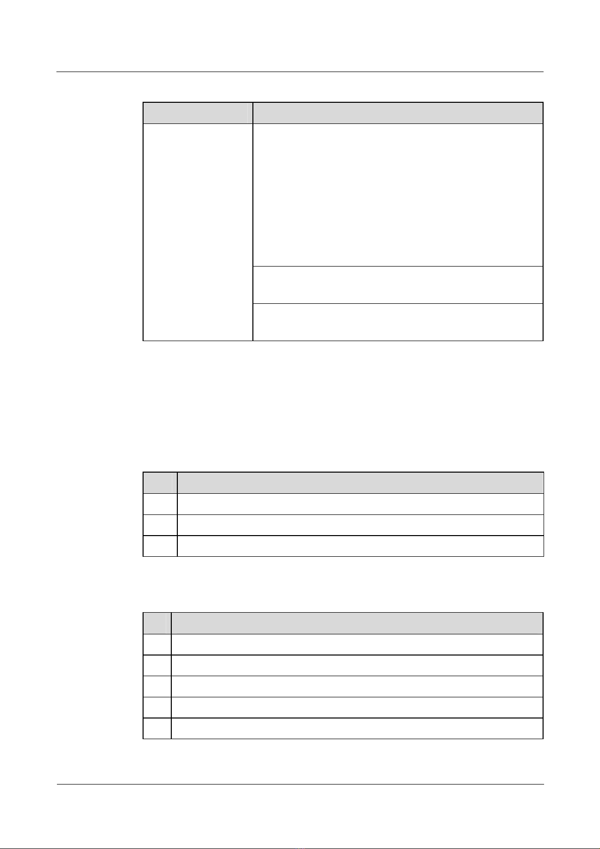
This document consists of four chapters and is organized as follows.
Issue 5.3 (
Chapter Content
1 LAN access overview This chapter provides a conceptual overview of the physical
2 MAC address table
configuration
30 March 2009)
and logical interfaces and the link layer protocols supported by
the Secure Router 8000 Series.
This chapter describes the fundamentals of the MAC address
table and provides configuration procedures and examples.
Nortel Networks Inc.
1
Page 13
About this document
Nortel Secure Router 8000 Series
Configuration - LAN Access and MAN Access
Chapter Content
3 Ethernet interface
configuration
4 VLAN configuration This chapter describes the conditions in which a Virtual Local
Appendix A: Glossary;
Appendix B: Acronyms
and abbreviations
Index This section lists important keywords used in this manual to
Conventions
This section describes the symbol and text conventions used in th is document
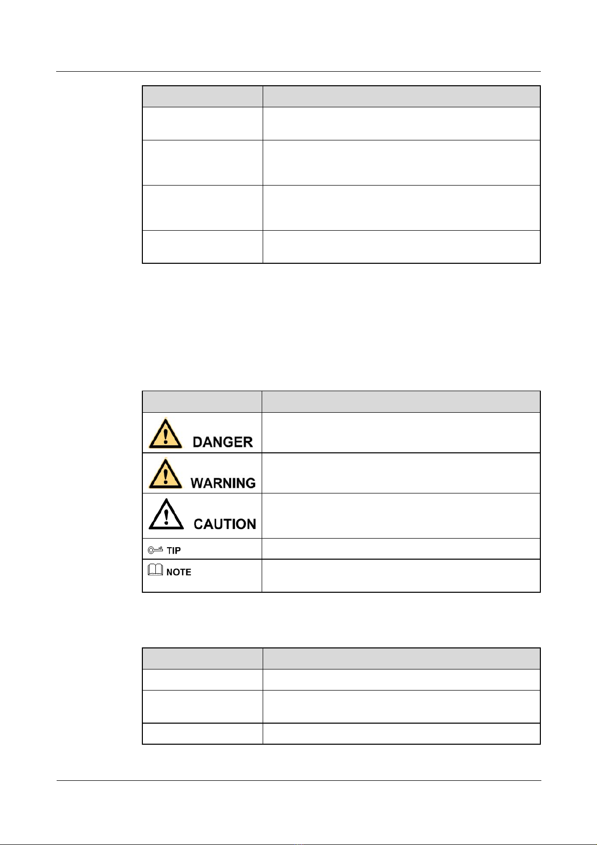
Symbol conventions
Symbol Description
This chapter describes the significance of the Ethernet network
and provides configuration procedures and examples.
Area Network (VLAN) is used and provides configuration
procedures and examples.
This section collates the glossary and frequently used
acronyms and abbreviations.
help you access information quickly.
General conventions
Convention Description
Times New Roman Normal paragraphs are in Times New Roman font.
Boldface
Indicates a hazard with a high level of risk that, if not avoided,
can result in death or serious injury.
Indicates a hazard with a medium or low level of risk that, if
not avoided, can result in minor or moderate injury.
Indicates a potentially hazardous situation that, if not avoided,
can cause equipment damage, data loss, and performance
degradation, or unexpected results.
Indicates a tip that may help you solve a problem or save time.
Provides additional information to emphasize or supplement
important points of the main text.
Names of files, directories, folders, and users are in boldface.
For example, log on as the user root.
Italic Book titles are in italics.
2
Nortel Networks Inc.
Issue 5.3 (30 March 2009)
Page 14
Nortel Secure Router 8000 Series
Configuration - LAN Access and MAN Access About this document
Convention Description
Courier New
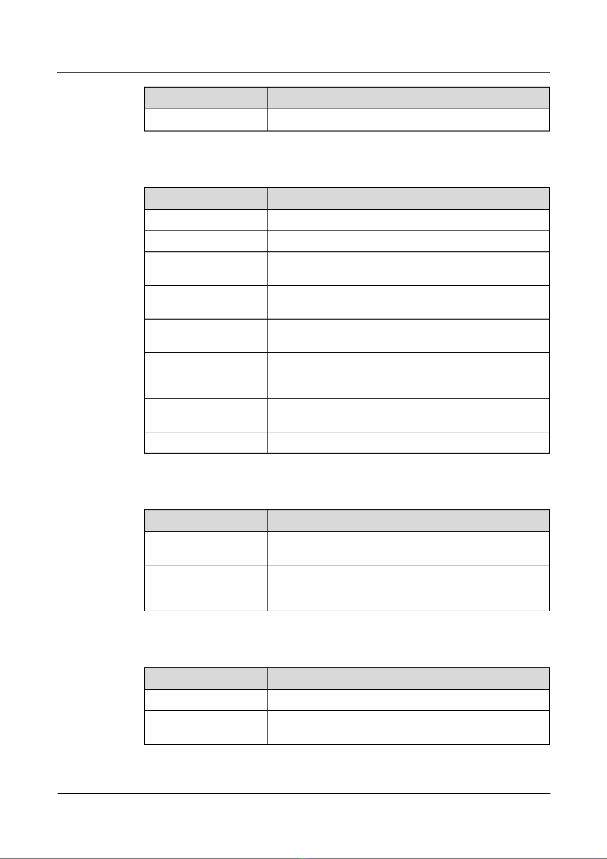
Command conventions
Convention Description
Boldface
Italic Command arguments are in italics.
[ ] Items (keywords or arguments) in square brackets [ ] are
{ x | y | ... } Alternative items are grouped in braces and separated by
[ x | y | ... ] Optional alternative items are grouped in square brackets and
{ x | y | ... } * Alternative items are grouped in braces and separated by
&<1-n> The parameter before the ampersand sign (&) can be repeated
Terminal display is in Courier New font.
The keywords of a command line are in boldface.
optional.
vertical bars. You select one item.
separated by vertical bars. You can select one item or no item.
vertical bars. You can select a minimum of one item or a
maximum of all items.
1 to n times.
# A line starting with the number sign (#) contains comments.
GUI conventions
Convention Description
Boldface
> Multilevel menus are in boldface and separated by the
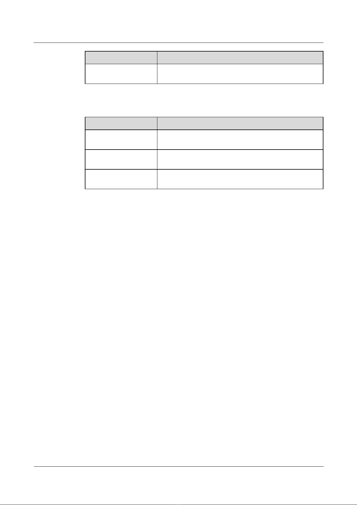
Keyboard operation
Format Description
Key
Key 1+Key 2
Buttons, menus, parameters, tabs, windows, and dialog box
titles are in boldface. For example, click OK.
right-angled bracket sign (>). For example, choose File >
Create > Folder.
Press the key. For example, press Enter and press Tab.
Press the keys concurrently. For example, Ctrl+Alt+A means
press the three keys concurrently.
Issue 5.3 (
30 March 2009)
Nortel Networks Inc.
3
Page 15
About this document
Format Description
Key 1, Key 2 Press the keys in sequence. For example, Alt, A means press
Mouse operation
Action Description
Click Select and release the primary mouse button without moving
Double-click Press the primary mouse button twice quickly without moving
Drag Press and hold the primary mouse button and move the pointer
Nortel Secure Router 8000 Series
Configuration - LAN Access and MAN Access
the two keys in sequence.
the pointer.
the pointer.
to a new position.
Update history
Updates between document versions are cumulative. Therefore, the latest document version
contains all updates made to previous versions.
Updates in Issue 01 (2008-06-06)
This is the initial field trial release of this document.
4
Nortel Networks Inc.
Issue 5.3 (30 March 2009)
Page 16

Nortel Secure Router 8000 Series
Configuration - LAN Access and MAN Access
Contents
1 LAN access overview.................................................................................................................1-1
1.1 Introduction...................................................................................................................................................1-2
1.1.1 LAN interfaces.....................................................................................................................................1-2
1.1.2 Link layer protocols.............................................................................................................................1-3
1.2 Configuring interface parameters..................................................................................................................1-3
1.2.1 Establishing the configuration task ......................................................................................................1-3
1.2.2 Entering the interface view..................................................................................................................1-5
1.2.3 Configuring the interface description...................................................................................................1-5
1.2.4 Configuring the interval of flow statistics............................................................................................1-5
1.2.5 Enabling the interface ..........................................................................................................................1-6
1.2.6 Checking the configuration..................................................................................................................1-7
1.3 Maintaining interfaces...................................................................................................................................1-8
1.3.1 Clearing interface statistics..................................................................................................................1-8
1.3.2 Debugging the interface.......................................................................................................................1-8
Issue 5.3 (
30 March 2009) Nortel Networks Inc. i
Page 17

Page 18

Nortel Secure Router 8000 Series
Configuration - LAN Access and MAN Access
Tables
Table 1-1 Command line views and prompts of physical interfaces...................................................................1-2
Table 1-2 Command line views and prompts of logical interfaces.....................................................................1-3
Table 1-3 Interface numbering............................................................................................................................1-4
Issue 5.3 (
30 March 2009) Nortel Networks Inc. iii
Page 19

Page 20
Nortel Secure Router 8000 Series
Configuration - LAN Access and MAN Access 1 LAN access overview
1 LAN access overview
About this
chapter
T le shows the con
he following tab tents of this chapter.
Section Description
1.1 Introduction describes local area network (LAN) This section
interfaces and link layer protocols.
1.2 Configuring interface
parameters
1.3 Maintaining interfaces This section describes how to maintain LAN interfaces.
This section describes how to configure LAN interface
parameters.
Issue 5.3 (
30 March 2009) Nortel Networks Inc. 1-1
Page 21

1 LAN access overview
1.1 Introduction
This chapter describes the concepts of physical and logical interfaces and the link layer
protocols supported by the Nortel Secure Router 8000 Series. This chapter also describes how
to configure LAN interface parameters and maintain LAN interfaces.
For the information about wide area network (WAN) configuration, network layer protocols,
and special functions, see Nortel Secure Router 8000 Series Configuration – WAN Access
(NN46240-503).
The section describes the concepts that you need to know before you configure LAN
interfaces and link layer protocols:
z
LAN interfaces
z
Link layer protocols
1.1.1 LAN interfaces
Interface types
Nortel Secure Router 8000 Series
Configuration - LAN Access and MAN Access
Routers use two types of interfaces to exchange data and interact with other devices on the
network: physical interfaces and logical interfaces.
z
Physical interfaces have corresponding physical components. They are further divided
into two types.
− Local area network (LAN) interfaces: LAN interfaces are mainly Ethernet interfaces
through which routers exchange
− Wide area network (WAN) interfaces: WAN interfaces include ATM, POS, and
CE1/CT1 interfaces through which routers exchange data with devices of external
networks.
z
Logical interfaces, such as subinterfaces, do not physically exist. They are created
through configuration.
Command views and prompts
The following tables show the command line views and prompts of physical interfaces and
logical interfaces.
Table 1-1 Command line views and prompts of physical interfaces
Interface Command
View
Ethernet
interface
Ethernet
interface view
data with devices in a LAN.
Command Prompt
Run the interface
[Nortel-Ethernet1/0/0]
ethernet 1/0/0
command in the
system view.
Gigabit Ethernet
interface
Gigabit Ethernet
interface view
Run the interface
gigabitethernet 1/0/0
[Nortel-GigabitEthernet1/0
/0]
command in the
system view.
1-2 Nortel Networks Inc. Issue 5.3 (
30 March 2009)
Page 22

Nortel Secure Router 8000 Series
Configuration - LAN Access and MAN Access 1 LAN access overview
Table 1-2 Command line views and prom pts of logical interfaces
Interface Command
View
Ethernet
subinterface
GigabitEthernet
subinterface
Ethernet
subinterface
view
GigabitEthernet
subinterface
view
1.1.2 Link layer protocols
The link layer provides reliable transmission of data from one site to another. The link layer
receives packets from the network layer and then encapsulates packets into frames to deliver
them to the physical layer.
The Nortel Secure Router 8000 Series supports LAN link layer protocols as follows:
z
The Virtual Local Area Network (VLAN) divides a physical LAN into several logical
subnets, regardless of their physical locations.
z
Data transmission within a VLAN does not interfere with that in other VLANs. This
enhances the network security.
Command Prompt
Run the interface
ethernet 1/0/0.1
command in the
system view.
Run the interface
gigabitethernet
1/0/0.1 command in
the system view
[Nortel-Ethernet1/0/0.1]
[Nortel-Gigabitethernet1/0
/0.1]
1.2 Configuring interface parameters
1.2.1 Establishing the configuration task
Applicable environment
The section describes how to configure the LAN interfaces. With the Nortel Secure Router
8000 Series, you configure and maintain interfaces from the interface views.
The following table describes interface numbering for the Secure Router 8000 Series routers.
Issue 5.3 (
30 March 2009) Nortel Networks Inc. 1-3
Page 23
1 LAN access overview
Table 1-3 Interface num bering
Product Numbering
Nortel Secure Router 8000 Series
Configuration - LAN Access and MAN Access
SR8000 routers
Preconfiguration tasks
Before you configure an interface, install the interface card on the router.
Slot:
SR8002, SR8004, and SR8008: numbered from left to right and
from the top down on the front chassis.
z
SR8008: 0 to 8
z
SR8004: 0 to 4
z
SR8002: 0 to 2
SR8012: numbered from left to right and from the bottom up on
the front chassis.
z
SR8012: 1 to 10
Card number: numbered from 0.
If there is no pinch board, the number is fixed 0.
Interface number: numbered from 0.
Marked on each interface board.
Data preparation
To configure an interface, you need the following data.
No. Data
1 Interface type and interface number
2 Description of the interface
3 Interval for traffic statistics on the interface (optional)
Configuration procedures
No. Procedure
1 Entering the interface view
2 Configuring the interface description
3 Configuring the interval of flow statistics
4 Enabling the interface
5 Checking the configuration
1-4 Nortel Networks Inc. Issue 5.3 (
30 March 2009)
Page 24

Nortel Secure Router 8000 Series
Configuration - LAN Access and MAN Access 1 LAN access overview
1.2.2 Entering the interface view
Do as follows on the routers:
Step 1 Run:
system-view
The system view appears.
Step 2 Run:
interface interface-type interface-number
The interface view appears.
For an overview of interface numbering, see
Table 1-3.
For detailed information about interface numbering, see Nortel Secure Router 8000 Series –
Installation (NN46240-300 or NN46240-301).
----End
1.2.3 Configuring the interface description
Before you configure an interface, you need to understand the networking requirements and
know the following information:
z
how the physical interface is connected
z
the working mode and parameters that are required for the interface
z
the negotiated link layer protocol and working parameters between the interface and the
peer interface
z
the network protocol address supported by the interface
z
the static route or dynamic routing protocol on the interface
z
parameters for packet filtering and Network Address Translation (NAT) if a firewall is
set up on the interface
NOTE
e Secure Router 8000 Series supports the description interface-description command in the interface
Th
view, which configures the interface description. The description identifies the interface function and is
useful for interface maintenance.
1.2.4 Configuring the interval of flow statistics
Configuring the global interval of flow statistics
Do as follows on the routers:
Step 1 Run:
system-view
The system view appears.
Step 2 Run:
interface traffic sampling-time time global
Issue 5.3 (
30 March 2009) Nortel Networks Inc. 1-5
Page 25
1 LAN access overview
Configuration - LAN Access and MAN Access
This command configures the global interval of flow statistics.
The interval of traffic statistics configured by this command can be applied to each physical interface.
----End
Configuring the interface interval of flow statistics
Do as follows on the routers:
Step 1 Run:
system-view
The system view appears.
Step 2 Run:
interface interface-type interface-number
The specified interface view appears.
Step 3 Run:
Nortel Secure Router 8000 Series
interface traffic sampling-time time
This command configures the interface interval of flow statistics.
z
When the global interval of flow statistics and the interface interval of flow statistics are configured
at the same time, the interface selects the interface interval of flow statistics first.
z
The physical interfaces support the configuration of the interval of flow statistics. For logical
interfaces, the interval of flow statistics uses the default system value and cannot be changed through
configuration.
----End
1.2.5 Enabling the interface
After you configure the interface, enable the interface and note the following:
z
When a physical interface is idle and not connected to cables, shut down the interface to
protect it from interference.
z
After the interface configuration is complete, run the restart command, or run the
shutdown and undo shutdown commands consecutively, to validate the configuration.
Running the restart command is the same as running the shutdown and the undo
shutdown commands consecutively.
NOTE
When subinterfaces exist, if you run the shutdown command and the undo shutdown command on the
main interface in succession, the two commands must be used at an interval of at least 15 seconds.
When the interface status or the protocol status changes, the output automatically appears, as
shown in the following example:
%Jan 22 17:24:54 2007 Nortel IFNET/2/UPDOWN:Line protocol on the interface Ethe
rnet1/1/1 turns into UP state
1-6 Nortel Networks Inc. Issue 5.3 (
30 March 2009)
Page 26

Nortel Secure Router 8000 Series
Configuration - LAN Access and MAN Access 1 LAN access overview
1.2.6 Checking the configuration
Run the following commands to check the previous configuration.
Action Command
Check the interface running
status and statistics.
Check brief IP information on
the interface.
display interface [ interface-type [ interface-number ] ]
| { begin | exclude | include } regular-expression ]
[
display ip interface brief [ interface-type
[ interface-number ] ]
Run the display interface command. If the physical status, link layer protocol status, IP
address, mask, MAC address, and physical parameters of an interface are displayed, the
configuration is successful. For example:
<Nortel> display interface ethernet 2/0/0
Ethernet2/0/0 current state : UP
Line protocol current state : UP
Description : NORTEL, Nortel Series, Ethernet2/0/0 Interface
The Maximum Transmit Unit is 1500 bytes, Hold timer is 10(sec)
Internet Address is 100.1.3.1/24
IP Sending Frames' Format is PKTFMT_ETHNT_2, Hardware address is 00e0-fc00-8fe1
Output queue : (Urgent queue : Size/Length/Discards) 0/50/0
Output queue : (Protocol queue : Size/Length/Discards) 0/1000/0
Output queue : (FIFO queue : Size/Length/Discards) 0/256/0
auto negotiation, speed 100M, duplex full, loopback not set
Last 300 seconds input rate 1111 bytes/sec, 1 packets/sec
Last 300 seconds output rate 349 bytes/sec, 0 packets/sec
Usage of input bandwidth:0.01%,Usage of output bandwidth:0.00%
Input: 1104 packets, 1134603 bytes
1 broadcasts, 1070 multicasts, 0 pauses
0 InvalidVlanPkts, 0 InvalidVlanOctets
0 errors, 0 shorts, 0 longs
0 physical errors, 0 input fragments
0 Jabbers, 0 CRCs, 0 overruns
Output: 402 packets, 362974 bytes
17 broadcasts, 368 multicasts
0 InvalidVlanPkts, 0 InvalidVlanOctets
0 shorts, 0 longs
0 runts, 0 Jabbers, 0 CRCs
0 deferrals, 0 underruns, 0 aborts
0 collisions, 0 lates, 0 singles, 0 multiples, 0 excessives
Issue 5.3 (
Run the display ip interface brief command. If the physical status, link layer protocol status,
IP address, loopback status, and description of an interface are displayed, the configuration is
successful. For example:
<Nortel> display ip interface brief gigabitethernet 1/0/0
*down: administratively down
(l): loopback
(s): spoofing
Interface IP Address Physical Protocol Description
GigabitEthernet1/0/0 10.5.40.1 down down Nortel
30 March 2009) Nortel Networks Inc. 1-7
Page 27

1 LAN access overview
1.3 Maintaining interfaces
This section covers the following topics:
z
Clearing interface statistics
z
Debugging the interface
1.3.1 Clearing interface statistics
You cannot restore interface statistics after you clear them. Be sure that you want to clear the
statistics before you use the command.
To clear the statistics, run the following reset command in the user view.
Action Command
Nortel Secure Router 8000 Series
Configuration - LAN Access and MAN Access
Clear the interface statistics. reset counters interface [ interface-type
1.3.2 Debugging the interface
Debugging affects system performance. After you debug the interface, run the undo
debugging all command to disable debugging.
When a fault occurs on an interface, run the debugging command in the user view to locate
the fault.
For information about the debugging command related to specific interfaces, see the
corresponding maintenance sections in subsequent chap ters in this document.
[ interface-number ] ]
1-8 Nortel Networks Inc. Issue 5.3 (
30 March 2009)
Page 28

Nortel Secure Router 8000 Series
Configuration - LAN Access and MAN Access
Contents
2 MAC address table configuration...........................................................................................2-1
2.1 Introduction...................................................................................................................................................2-2
2.1.1 MAC address table overview...............................................................................................................2-2
2.1.2 Classification of MAC address entries.................................................................................................2-2
2.1.3 MAC address learning limit.................................................................................................................2-2
2.2 Configuring a MAC address table.................................................................................................................2-3
2.2.1 Establishing the configuration task ......................................................................................................2-3
2.2.2 Changing MAC address entries ...........................................................................................................2-3
2.2.3 Setting the aging time of a MAC address table....................................................................................2-4
2.2.4 Checking the configuration..................................................................................................................2-4
2.3 Configuring the MAC address learning limit................................................................................................2-5
2.3.1 Establishing the configuration task ......................................................................................................2-5
2.3.2 Configuring MAC address learning limit rules based on a VSI...........................................................2-6
2.3.3 Checking the configuration..................................................................................................................2-7
2.4 Configuration examples................................................................................................................................2-7
2.4.1 Example of configuring a MAC address table.....................................................................................2-7
2.4.2 Example of configuring the MAC address learning limit based on a VSI...........................................2-8
2.5 Troubleshooting.............................................................................................................................................2-9
Issue 5.3 (
30 March 2009) Nortel Networks Inc. i
Page 29

Page 30

Nortel Secure Router 8000 Series
Configuration - LAN Access and MAN Access 2 MAC address table configuration
2 MAC address table configuration
About this
chapter
T le shows the con
he following tab tents of this chapter.
Section Description
2.1 Introduction f the MAC address This section provides an overview o
table.
2.2 Configuring a MAC
address table
2.3 Configuring the MAC ow to configure the MAC address
address learning limit
2.4 Configuration examples
2.5 Troubleshooting This section describes how to diagnose and remove
This section describes how to configure the basic
functions of a M
Example of configuring a MAC address table.”
See “
This section describes h
learning limit.
See “Example of con
limit based on a VSI.”
This section provides configuration examples for the
MAC address table.
operational faults related to the MAC address table.
AC address table.
figuring the MAC address learning
Issue 5.3 (
30 March 2009) Nortel Networks Inc. 2-1
Page 31

2 MAC address table configuration
2.1 Introduction
This section describes the concepts that you need to know before you configure a MAC
address table:
z
MAC address table overview
z
Classification of MAC address entries
z
MAC address learning limit
2.1.1 MAC address table overview
Each station or server, which is attached to a port on a router, has its own unique MAC
address. The MAC address table of a router contains the MAC addresses of all the devices
that are connected to the router.
Generally, a router automatically creates MAC address tables by learning the source addresses
of the connected devices.
Network administrators can manually bind a MAC address and a port in the table. This can
prevent malicious users with a counterfeit MAC address from logging on to the local device
through other switches.
Nortel Secure Router 8000 Series
Configuration - LAN Access and MAN Access
2.1.2 Classification of MAC address entries
MAC address entries are classified into the following three types:
z
Dynamic entries: Dynamic entries are learned and stored on interface boards. Dynamic
entries expire and are lost after hot swapping, interface-board resetting, or router
rebooting.
z
Static entries: Users configure static entries, which are automatically delivered to each
interface board. Static entries do not expire and are not lost after hot swapping,
interface-board resetting, or router rebooting.
z
Blackhole entries: Users configure blackhole entries, which are used to discard frames
containing a specified MAC address and are delivered to each interface board. Blackhole
entries do not expire and are not lost after hot swapping, or interface-board resetting, or
router rebooting.
2.1.3 MAC address learning limit
As a basic feature of Layer 2 forwarding, MAC address learning is automatically performed.
Thus, the learning process, which results in frequent attacks, is difficult to control.
By restricting the quantity of MAC addresses learned, you can control user access because the
MAC address is the basis of Layer 2 forwarding.
The MAC address learning limit controls MAC address learning by:
z
setting the maximum number of MAC addresses to be learned
z
controlling the speed of MAC addresses learning
z
discarding or forwarding packets after the maximum number or speed of MAC address
learning is reached
z
alarming network administrators after the maximum number or speed of MAC address
learning is reached
2-2 Nortel Networks Inc. Issue 5.3 (
30 March 2009)
Page 32

Nortel Secure Router 8000 Series
Configuration - LAN Access and MAN Access 2 MAC address table configuration
Currently, you can set the MAC address learning limit on a Virtual Swit ch Instance (VSI).
NOTE
The MAC address learning limit is available only on Layer 2 interfaces, such as Fast Ethernet (FE) and
Gigabit Ethernet (GE), except for the 10GE interface. It is unavailable on other physical interfaces,
logical interfaces, and subinterfaces.
2.2 Configuring a MAC address table
2.2.1 Establishing the configuration task
Applicable environment
To use a MAC address table, you need to configure the basic functions of the MAC address
table.
Preconfiguration tasks
None
Data preparation
To configure a MAC address table, you need the following data.
No. Data
1 MAC address
2 Port number
3 Aging time of the MAC address table
Configuration procedures
No. Procedure
1 Changing MAC address entries (optional)
2 Setting the aging time of a MAC address table (optional)
3 Checking the configuration
2.2.2 Changing MAC address entries
Do as follows on all routers:
Step 1 Run:
system-view
Issue 5.3 (
30 March 2009) Nortel Networks Inc. 2-3
Page 33

2 MAC address table configuration
The system view appears.
Step 2 Add or delete MAC address entries.
z
Run:
mac-address { blackhole | static } mac-address interface-type interface-number vsi
vsi-name
This command adds the MAC address entries. Note the following:
− You can add only unicast MAC addresses, not multicast MAC addresses or
special MAC addresses, to a MAC address table. Special MAC addresses are
reserved for special usage, such as the MAC addresses of special packets.
− You can add a maximum of 1024 nondynamic entries.
− The interface specified in the mac-address command must be a switched
interface, serving as an outgoing interface for Layer 2 forwarding.
z
Run:
undo mac-address mac-address vsi vsi-name
undo mac-address { all | blackhole | dynamic | static }
This command deletes the MAC address entries.
Nortel Secure Router 8000 Series
Configuration - LAN Access and MAN Access
----End
2.2.3 Setting the aging time of a MAC address table
Do as follows on all routers:
Step 1 Run:
system-view
The system view appears.
Step 2 Run:
mac-address aging-time interval
This command configures the aging time of the MAC address table.
In a MAC address table, only dynamic entries age. The aging time ranges from 10 to
1000000 seconds. The default is 300 seconds. The aging time 0 means that no MAC address
entries age.
----End
2.2.4 Checking the configuration
Run the following commands to check the previous configuration.
Action Command
Check information about a MAC address
entry.
display mac-address mac-address vsi
vsi-name
display mac-address [ blackhole | static |
dynamic ]
2-4 Nortel Networks Inc. Issue 5.3 (
30 March 2009)
Page 34

Nortel Secure Router 8000 Series
Configuration - LAN Access and MAN Access 2 MAC address table configuration
Action Command
Check the aging time of a static MAC
display mac-address aging-time
address entry.
Run the display mac-address command. If MAC addresses, outgoing interfaces, and types of
MAC addresses are displayed, the configuration is successful. For example:
<Nortel> display mac-address 0011-2233-4455 vsi 2
MAC Address VSI ID Port Type Lsp
------------------------------------------------------------------0011-2233-4455 2 Ethernet3/0/14 static 3/-
Total matching items displayed = 1
Run the display mac-address aging-time command. If the aging time of a MAC address
entry is displayed, the configuration is successful. For example:
<Nortel> display mac-address aging-time
Aging time: 300 seconds
2.3 Configuring the MAC address learning limit
2.3.1 Establishing the configuration task
Applicable environment
Generally, the MAC address learning limit is applied to networks that have fixed access users,
but which lack security management, such as a residential-district network or an enterprise
intranet that lacks security control.
After a MAC address learning limit is configured, the MAC address of a new user is not
added into the address table after the limit of access users is reached. The new traffic is
broadcast with limited speed.
Preconfiguration tasks
You need to clear the MAC addresses learned on a port before you configure the MAC
address learning limit.
Data preparation
To configure the MAC address learning limit, you need the following data.
No. Data
1 MAC address learning limit rules
Issue 5.3 (
30 March 2009) Nortel Networks Inc. 2-5
Page 35

Nortel Secure Router 8000 Series
2 MAC address table configuration
Configuration - LAN Access and MAN Access
Configuration procedures
No. Procedure
1 Configuring MAC address learning limit rules based on a VSI (optional)
2 Checking the configuration
NOTE
After the first rule of the MAC address learning limit is configured, the limit is automatically enabled
globally. After the last rule of the MAC address learning limit is removed, the limit is automatically
disabled globally.
2.3.2 Configuring MAC address learning limit rules based on a VSI
If learned MAC addresses exist on a port, run the undo mac-address dynamic command in
the system view to clear those addresses. Otherwise, MAC address learnin g can no t be
accurately limited.
The MAC address learning limit is implemented on a created VSI. To create a VSI, see Nortel
Secure Router 8000 Series Commands Reference (NN46240-500).
Do as follows on all routers:
Step 1 Run:
system-view
The system view appears.
Step 2 Run:
vsi vsi-name [ auto | static ]
The VSI view appears.
Step 3 Run:
mac-limit maximum max rate interval
This command configures the MAC address learning limit rule in the VSI.
Step 4 Run:
mac-limit action { discard | forward }
This command configures the action to take after the address learning limit is reached.
Step 5 Run:
mac-limit vlan vlan-id1 [ to vlan-id2 ] alarm { disable | enable }
This command configures the alarm function after the address learning limit is reached.
2-6 Nortel Networks Inc. Issue 5.3 (
30 March 2009)
Page 36

Nortel Secure Router 8000 Series
Configuration - LAN Access and MAN Access 2 MAC address table configuration
----End
NOTE
Step 3 to Step 5 can be combined to form one command: mac-limit { action { discard | forward } |
alarm { disable | enable } | maximum max rate interval } *.
2.3.3 Checking the configuration
Run the following commands to check the previous configuration.
Action Command
Check MAC address
learning limit rules.
display mac-limit [ vsi vsi-name | interface-type
interface-number ]
Run the display mac-limit command to view the number of limit rules, the maximum number
of MAC address learning, the learning rate, the action performed, and whether to alarm after
the limit is reached. For example:
<Nortel> display mac-limit
MAC Limit is enabled
Total MAC Limit rule count : 2
PORT VLAN/VSI Maximum Rate(ms) Action Alarm
---------------------------------------------------------------------GigabitEthernet1/0/0 - 10 0 discard enable
- 1 1000 100 forward enable
2.4 Configuration examples
This section consists of the following examples:
z
Example of configuring a MAC address table
z
Example of configuring the MAC address learning limit based on a VSI
2.4.1 Example of configuring a MAC address table
Networking requirements
To prevent a MAC address entry in a user’s MAC address table from aging, configure the
entry as a static entry. Configure the aging time of other dynamic entries to 500 seconds.
Configuration roadmap
The configuration roadmap is as follows:
z
Configure the static address entry.
z
Configure the aging time.
Issue 5.3 (
30 March 2009) Nortel Networks Inc. 2-7
Page 37

2 MAC address table configuration
Data preparation
To complete the configuration, you need the following data:
z
The MAC address of the user is 0011-2233-4455.
z
The name of the VSI to which the interface belongs is vsi2.
z
The port is GE 1/0/0.
z
The aging time is 500 seconds.
Configuration procedure
Step 1 Configure the static MAC address entry.
[Nortel] mac-address static 0011-2233-4455 gigabitethernet 1/0/0 vsi vsi2
Step 2 Set the aging time of dynamic entries to 500 seconds.
[Nortel] mac-address aging-time 500
----End
Nortel Secure Router 8000 Series
Configuration - LAN Access and MAN Access
Configuration files
#
sysname Nortel
#
Vsi vsi2
#
mac-address aging-time 500
#
interface GigabitEthernet1/0/0
mac-address static 0011-2233-4455 GigabitEthernet1/0/0 vsi 2
#
return
2.4.2 Example of configuring the MAC address learning limit based on a VSI
Networking requirements
To enhance security, configure the MAC address learning limit on VSI vsi1.
Configuration roadmap
The configuration roadmap is as follows:
z
Configure the limit rules.
z
Enable the MAC address learning limit feature.
Configuration procedure
# Configure the maximum number of MAC addresses that can be learned to 100, and
configure the maximum rate for learning a MAC address to 50 milliseconds (ms) on VSI vsi1.
2-8 Nortel Networks Inc. Issue 5.3 (
30 March 2009)
Page 38

Nortel Secure Router 8000 Series
Configuration - LAN Access and MAN Access 2 MAC address table configuration
<Nortel> system-view
[Nortel] vsi vsi1
[Nortel-vsi-vsi1] mac-limit maximum 100 rate 50
[Nortel-vsi-vsi1] quit
# Check whether the configuration is valid.
[Nortel] display mac-limit
MAC Limit is enabled
Total MAC Limit rule count : 1
PORT VLAN/VSI Maximum Rate(ms) Action Alarm
--------------------------------------------------------------------------
- vsi1 100 50 discard enable
# Check the MAC address learning states.
[Nortel] display mac-limit vsi vsi1
Vsi1 MAC limit:
Maximum MAC count 100, rate 50(ms)
Action: discard, Alarm: enable
Configuration files
#
sysname Nortel
#
vsi vsi1
#
vsi vsi1
mac-limit maximum 100 rate 50
#
return
2.5 Troubleshooting
Fault description
The mac-address command fails to add a MAC address entry.
Fault analysis
The possible causes are as follows:
z
The MAC address is a multicast address.
z
The configured nondynamic entries exceed 1024.
Troubleshooting procedure
Step 1 Check whether the configured MAC address is a multicast address. Multicast address entries
are not allowed in a MAC address table.
Issue 5.3 (
30 March 2009) Nortel Networks Inc. 2-9
Page 39

2 MAC address table configuration
Step 2 Use the display mac-address command to check whether the configured nondynamic entries
exceed 1024. The system allows a maximum of 1024 nondynamic entries. For the Secure
Router 8000 Series, the maximum number of MAC addresses that can be learned is 64 K.
----End
Nortel Secure Router 8000 Series
Configuration - LAN Access and MAN Access
2-10 Nortel Networks Inc. Issue 5.3 (
30 March 2009)
Page 40

Nortel Secure Router 8000 Series
Configuration - LAN Access and MAN Access
Contents
3 Ethernet interface configuration .............................................................................................3-1
3.1 Introduction...................................................................................................................................................3-2
3.1.1 Introduction to Ethernet interfaces.......................................................................................................3-2
3.1.2 Classification of Ethernet interfaces....................................................................................................3-2
3.2 Configuring Ethernet interfaces....................................................................................................................3-2
3.2.1 Establishing the configuration task ......................................................................................................3-2
3.2.2 Assigning an IP address to an Ethernet interface .................................................................................3-3
3.2.3 Configuring the MTU of an Ethernet interface ....................................................................................3-4
3.2.4 Configuring the working mode of an Ethernet electrical interface......................................................3-5
3.2.5 Configuring the speed of an Ethernet electrical interface....................................................................3-5
3.2.6 Configuring the loopback function of an Ethernet interface................................................................3-6
3.2.7 Configuring the preamble length for packets sent by the Ethernet interface .......................................3-6
3.2.8 Checking the configuration..................................................................................................................3-7
3.3 Maintaining Ethernet interfaces....................................................................................................................3-8
3.4 Configuration examples................................................................................................................................3-8
3.4.1 Example of configuring an Ethernet interface.....................................................................................3-8
3.5 Troubleshooting...........................................................................................................................................3-11
3.5.1 Pinging the Ethernet interface fails....................................................................................................3-11
3.5.2 Ethernet interfaces cannot receive and send packets..........................................................................3-11
3.5.3 Ethernet interfaces discard packets....................................................................................................3-12
Issue 5.3 (
30 March 2009) Nortel Networks Inc. i
Page 41

Page 42

Nortel Secure Router 8000 Series
Configuration - LAN Access and MAN Access
Figures
Figure 3-1 Networking diagram of Ethernet interface configuration.................................................................3-9
Issue 5.3 (
30 March 2009) Nortel Networks Inc. iii
Page 43

Page 44

Nortel Secure Router 8000 Series
Configuration - LAN Access and MAN Access 3 Ethernet interface configuration
3 Ethernet interface configuration
About this
chapter
T le lists the conten
he following tab ts of this chapter.
Section Describes
3.1 Introduction n provides an overview of Ethernet interface This sectio
concepts.
3.2 Configuring Ethernet
interfaces
3.3 Maintaining Ethernet es how to debug the Ethernet
interfaces
3.4 Configuration examples of configuring the
3.5 Troubleshooting This section describes how to diagnose and remove faults
This section describes how to configure the Ethern
interface.
See “Example of configuring an Ethernet interface.”
This section describ
interface.
This section provides an example
Ethernet interface.
related to the Ethernet interface.
et
Issue 5.3 (
30 March 2009) Nortel Networks Inc. 3-1
Page 45

3 Ethernet interface configuration
Configuration - LAN Access and MAN Access
3.1 Introduction
This section describes the concepts that you need to know before you configure an Ethernet
interface:
z
Introduction to Ethernet interfaces
z
Classification of Ethernet interfaces
3.1.1 Introduction to Ethernet interfaces
Because it is flexible, simple, and easy to deploy, the Ethernet is an important form of local
area network (LAN) networking technology.
3.1.2 Classification of Ethernet interfaces
At present, the LAN interfaces supported by the Secure Router 8000 Series are the Ethernet
interfaces, including the traditional Ethernet electrical interface, Fast Ethernet interface, and
Gigabit Ethernet interface. The Secure Router 8000 Series supports the Layer 2 features of the
Ethernet interface. The following list des cribes the three Ether net interf aces:
Nortel Secure Router 8000 Series
z
The traditional Ethernet interface complies with 10Base-T specifications and can work at
the speed of 10 megabits per second (Mbit/s).
z
The Fast Ethernet (FE) interface complies with 100Base-TX specifications and is
compatible with 10Base-T specifications.
z
The Gigabit Ethernet (GE) interface complies with 1000Base-TX specifications and is
compatible with 10Base-T and 100Base-TX specifications.
Ethernet electrical interfaces can work in either full-duplex mode or half-duplex mode, and
they support autonegotiation. In autonegotiation mode, they negotiate with other network
devices for the most suitable workin g mode and speed, which simplifies system configuration
and management.
NOTE
z
This chapter explains the configuration of the FE and GE interfaces. The configuration of traditional
Ethernet interface is simple and similar to that of the FE interface.
z
Ethernet subinterfaces are applied in a Virtual Local Area Network (VLAN). For information about
Ethernet subinterfaces, see Chapter 4, “VLAN Configuration.”
3.2 Configuring Ethernet interfaces
3.2.1 Establishing the configuration task
Applicable environment
To configure the Ethernet to transmit data packets, you must configure Ethernet interfaces.
When you configure an Ethernet interface, you must assign an IP address to it. For other
parameters, you can use default values. If you have to change the values, keep them consistent
with the peer device.
3-2 Nortel Networks Inc. Issue 5.3 (
30 March 2009)
Page 46

Nortel Secure Router 8000 Series
Configuration - LAN Access and MAN Access 3 Ethernet interface configuration
Preconfiguration tasks
None
Data preparation
To configure an Ethernet interface, you need the following data.
No. Data
1 Interface number
2 IP address and mask of the Ethernet interface
3 Maximum Transmission Unit (MTU) of the Ethernet interface
Configuration procedures
No. Procedure
1 Assigning an IP address to an Ethernet interface
2 Configuring the MTU of an Ethernet interface (optional)
3 Configuring the working mode of an Ethernet electrical interface (optional)
4 Configuring the speed of an Ethernet electrical interface(optional)
5 Configuring the loopback function of an Ethernet interface (optional)
6 Configuring the preamble length for packets sent by the Ethernet interface
7 Checking the configuration
3.2.2 Assigning an IP address to an Ethernet interface
Do as follows on each router:
Step 1 Run:
system-view
The system view appears.
Step 2 Run:
Issue 5.3 (
interface { ethernet | gigabitethernet } interface-number
The Ethernet interface view appears.
Step 3 Run:
ip address ip-address { mask | mask-length } [ sub ]
This command configures the IP address of the Ethernet interface.
30 March 2009) Nortel Networks Inc. 3-3
Page 47

3 Ethernet interface configuration
----End
For more information about IP address configuration, see Nortel Secure Router 8000 Series
Configuration – IP Services (NN46249-504).
Nortel Secure Router 8000 Series
Configuration - LAN Access and MAN Access
When you configure two or more IP addresses on an Ethernet interfac
the first IP address are indicated by the key word sub.
3.2.3 Config
uring the MTU of an Ethernet interface
The MTU is
physica
NO
z
z
measured in bytes. The MTU range of Ethernet interfaces depends on the
l devices. By default, the MTU is 1500 bytes.
TE
After you change the MTU by using the mtu command on an interface, you need to restart the
interface to validate the newly configured value. To restart the interface, run the shutdown and undo
shutdown commands in succession, or run the restart command in the interface view.
If subinterfac
of at least 15 seconds.
Configuring the IPv4 MTU
on each router:
view appears.
Step 1
Step 2
Do as follows
Run:
-view
system
The system
Run:
e, addresses other than
es exist, the shutdown and the undo shutdown commands must be run at an interval
ace { ethernet | gigabitethernet } interface-number
interf
thernet interface view appears.
The E
Step 3
Run:
mtu mtu
This command configures the IPv4 MTU of the Ethernet interface.
----End
Configuring the IPv6 MTU
on each router:
view appears.
interface view appears.
Step 1
Step 2
Do as follows
Run:
-view
system
The system
Run:
ace { ethernet | gigabitethernet } interface-number
interf
The Ethernet
3-4 Nortel Networks Inc. Issue 5.3 (
30 March 2009)
Page 48

Nortel Secure Router 8000 Series
Configuration - LAN Access and MAN Access 3 Ethernet interface configuration
Step 3
Run:
ipv6 mtu
mtu
This command configures the IPv6 MTU of the Ethernet interface.
----End
3.2.4 Config mode of an Ethernet electrical
interfa
ce
Step 1
uring the working
Do as follows
Run:
system
on each router:
-view
The system view appears.
Step 2
Run:
ace { ethernet | gigabitethernet } interface-number
interf
The Ethernet interface view appears.
Step 3
Run:
duplex { ful
l | half | negotiation }
This
command configures the working mode of the interface.
NO
TE
z
Ethernet optical interfaces can work only in full-duplex mode.
z
hen connected to a hub, the Ethernet electrical interfaces of a router must work in half-duplex
W
mode. When connected to a LAN switch, the interfaces can work in either full-duplex mode or
half-duplex mode, but only if the mode is consistent with that on the peer device.
----End
3.2.5 Configuring the speed of an Ethernet electrical interface
on each router:
-view
ce view appears.
Step 1
Step 2
Do as follows
Run:
system
The system view appears.
Run:
interface { ethernet | gigabitethernet } interface-number
The interfa
Issue 5.3 (
Step 3 Perf n the type of interface (FE or GE):
30 March 2009) Nortel Networks Inc. 3-5
orm one of the following steps based o
z
Run:
speed {
10 | 100 | negotiation }
Page 49

3 Ethernet interface configuration
This command configures the speed of the FE electrical interface.
z
Run:
speed { 100 | negotiation }
Nortel Secure Router 8000 Series
Configuration - LAN Access and MAN Access
This co
mmand configures the speed of the GE electrical interface on the Secure Router
8012 Routing Process Unit (RPU).
NOTE
z
The default speed fo
but it must be consistent with that of the peer device.
z
A
speed of 1000 Mbit/s and half-duplex mode cannot be configured simultaneously on a GE
e
lectrical interface.
z
You do not need to configure the speed of an optical interface.
r FE and GE electrical interfaces is autonegotiation. You can change the speed,
----End
3.2.6 Configuring the loopback function of an Ethernet interface
on each router:
-view
ace { ethernet | gigabitethernet } interface-number
Step 1
Step 2
Do as follows
Run:
system
The system view appears.
Run:
interf
d Ethernet interface view appears.
e interface.
use the internal loopback function to test the interface. When an Ethernet interface
Step 3
The specifie
Run:
loopback
This command enables internal loopback on th
You can
operates normally, disable internal loopback.
----End
3.2.7 Config le length for packets sent by the
uring the preamb
Ethernet interface
on each router:
-view
rs.
Step 1
Step 2
Do as follows
Run:
system
The system view appea
Run:
preamble uncompress
3-6 Nortel Networks Inc. Issue 5.3 (
30 March 2009)
Page 50

Nortel Secure Router 8000 Series
Configuration - LAN Access and MAN Access 3 Ethernet interface configuration
Configure the preamble length for all packets sent by the Ethernet interface to 7 bytes.
By default, the preamble length of packets sent by the Secure Router 8000 Series is 6 bytes.
When the Secure Router 8000 Series cannot connect devices on which the default value of the
preamble length is 7 bytes, use the preamble uncompress com
length fo
r packets sent by the Ethernet interface to 7 bytes.
mand to change the preamble
----End
3.2.8 Check
ing the configuration
R llowing commands to che s configuration.
un the fo ck the previou
Action Command
Check the status of the specified
Ethernet interface.
For example: Display the status and statistics on Ethernet 2/0/0.
<Nortel> display interface etherne
Ethernet2/0/0 current state : UP
Line protocol current state : UP
Description : NORTEL, Nortel Series,
The Maximum Transmit Unit is 1500 bytes, Hold timer is 10(sec)
In
ternet Address is 10.1.1.1/24
IP Sending Frames' Format is PKTFMT_ETHNT_2, Hardware address
Output queue : (Urgent queue : Size/Length/Discards) 0/50/0
Output queue : (Protocol queue : Size/Length/Discards) 0/1000/0
Output queue : (FIFO queue : Size/Length/Discards) 0/256/0
auto negotiation, speed 100M, duplex full, loopback not set
Last 300 seconds input rate 98 bytes/sec, 1 packets/sec
Last 300 seconds output rate 69 byt
Usage of input bandwidth:0.00%,Usage of output
Input: 1735 packets, 130411 bytes
231 broadcasts, 20 multicasts
0 InvalidVlanPkts, 0 InvalidVlanOctets
0 errors, 0 shorts, 0 longs
0 physical errors, 0 input fr
0 Jabbers, 0 CRCs, 0 overruns
Output: 1474 packets, 113162 bytes
0 broadcasts, 0 mul
0 InvalidVlanPkts, 0 InvalidVlanOct
0 shorts, 0 longs
0 runts, 0 Jabbers, 0 CRCs
0 deferrals, 0 underruns, 0 aborts
0 collisions, 0 lates, 0 singles, 0 multiples, 0 excessives
display interface { ethernet | gigabitethernet }
[ interface-number ] [
| { begin | exclude | include }
regular-expression ]
t 2/0/0
Ethernet2/0/0 Interface
is 00e0-fc7a-5741
es/sec, 0 packets/sec
bandwidth:0.00%
ets
ticasts
, 0 pauses
a
gments
Issue 5.3 (
30 March 2009) Nortel Networks Inc. 3-7
Page 51

3 Ethernet interface configuration
3.3 Maintaining Ethernet interfaces
Debugging affects system performance. After you debug the Ethernet interface, run the undo
debugging all command to disable debugging.
When a fault occurs on an Ethernet interface, run the following debugging commands in the
user view to locate the fault.
For information about displaying debugging informatio n, see Nortel Secure Router 8000
Series Configuration – System Management (NN46240-601).
Action Command
Nortel Secure Router 8000 Series
Configuration - LAN Access and MAN Access
Enable debugging of the
Ethernet interface.
Enable debugging of the
Ethernet interface based on
the MAC address.
debugging ethernet packet [ arp | error | ip | ipv6 | isis |
l2vpn | mpls | pppoe ] [ verbose ] [ interface interface-type
interface-number ]
debugging ethernet packet mac { dest_mac dest-mac |
src_mac src_mac }
3.4 Configuration examples
This section provides an example procedure for configuring an Ethernet interface.
3.4.1 Example of configuring an Ethernet interface
Networking requirements
As shown in Figure 3-1, the Ethernet interfaces of Router A, Router B, and Router C are
connected to the IP network 202.38.165.0/24.
3-8 Nortel Networks Inc. Issue 5.3 (
30 March 2009)
Page 52

Nortel Secure Router 8000 Series
Configuration - LAN Access and MAN Access 3 Ethernet interface configuration
Figure 3-1 Netw orking diagram of Ether net interfa ce config uratio n
RouterA
GE1/0/0
202.38.165.1/24
Configuration roadmap
The configuration roadmap is as follows:
z
Configure a description for each router.
z
Configure IP addresses for interfaces on each router.
Data preparation
GE1/0/0
202.38.165.3/24
RouterC
RouterB
GE1/0/0
202.38.165.2/24
To configure an Ethernet interface, you need the following data:
z
Interface number
z
IP address of the interface
Configuration procedure
Step 1 Configure Router A.
<RouterA> system-view
[RouterA] interface gigabitethernet 1/0/0
[RouterA-GigabitEthernet1/0/0] description RouterA
[RouterA-GigabitEthernet1/0/0] ip address 202.38.165.1 255.255.255.0
[RouterA-GigabitEthernet1/0/0] quit
Step 2 Configure Router B.
<RouterB> system-view
[RouterB] interface gigabitethernet 1/0/0
[RouterB-GigabitEthernet1/0/0] description RouterB
[RouterB-GigabitEthernet1/0/0] ip address 202.38.165.2 255.255.255.0
[RouterB-GigabitEthernet1/0/0] quit
Step 3 Configure Router C.
<RouterC> system-view
[RouterC] interface gigabitethernet 1/0/0
[RouterC-GigabitEthernet1/0/0] description RouterC
[RouterC-GigabitEthernet1/0/0] ip address 202.38.165.3 255.255.255.0
[RouterC-GigabitEthernet1/0/0] quit
Issue 5.3 (
30 March 2009) Nortel Networks Inc. 3-9
Page 53

3 Ethernet interface configuration
Step 4 Verify the configuration.
After the configuration, you can use the following methods to check whether the configured
interface operates normally:
z
In the case of low traffic volume, ping the Ethernet interfaces of a router from another
router. If all the ping packets are returned, the interfaces are normal.
z
Check the statistics of a router. If the number of received error frames does not change,
the interfaces are normal.
Check the interface status of each router. In normal operation, the physical status and protocol
status are Up.
Consider Router A as an example:
<RouterA> display ip interface brief
*down: administratively down
(l): loopback
(s): spoofing
Interface IP Address Physical Protocol Description
GigabitEthernet1/0/0 202.38.165.1 up up RouterA
----End
Nortel Secure Router 8000 Series
Configuration - LAN Access and MAN Access
Configuration files
z
Configuration file of Router A:
#
sysname RouterA
#
interface GigabitEthernet1/0/0
ip address 202.38.165.1 255.255.255.0
description RouterA
#
return
z
Configuration file of Router B:
#
sysname RouterB
#
interface GigabitEthernet1/0/0
ip address 202.38.165.2 255.255.255.0
description RouterB
#
return
z
Configuration file of Router C:
#
sysname RouterC
#
interface GigabitEthernet1/0/0
ip address 202.38.165.3 255.255.255.0
description RouterC
#
return
3-10 Nortel Networks Inc. Issue 5.3 (
30 March 2009)
Page 54

Nortel Secure Router 8000 Series
Configuration - LAN Access and MAN Access 3 Ethernet interface configuration
3.5 Troubleshooting
This section provides methods for troubleshooting the following faults:
z
Pinging the Ethernet interface fails
z
Ethernet interfaces cannot receive and send packets
z
Ethernet interfaces discard packets
3.5.1 Pinging the Ethernet interface fails
Fault description
Pinging an Ethernet interface of a router on a PC fails.
Fault analysis
The possible causes are as follows:
z
The link connection is incorrect.
z
The IP address or mask of the interface is incorrect.
Troubleshooting procedure
Step 1 Check whether the PC and the router are connected correctly.
Check the status of the link indicator of the Ethernet interface that connects the router and the
PC:
z
If the indicator is on, the connection is correct.
z
If the indicator is off, check the physical devices, such as the network card, network
cable, and interface module of the router.
Step 2 Check that the IP address of the PC and that of the Ethernet interface on the router are in the
same subnet.
----End
3.5.2 Ethernet interfaces cannot receive and send packets
Fault description
The display of the 100 Mbit/s Ethernet interface on a router shows that no connection is set up.
The display of the 10 Mbit/s Ethernet interface on another router shows that the connection is
set up. However, the Active indicator on the physical layer constantly flashes, and packets are
not received and sent.
Fault analysis
Issue 5.3 (
30 March 2009) Nortel Networks Inc. 3-11
A possible cause is that the working speeds of the Ethernet interfaces on the two routers are
inconsistent.
Page 55

3 Ethernet interface configuration
When unshielded twisted pair is used in the Ethernet network, and at least one of the two
connected ends supports 100Base-TX, if the working speeds of the two ends do not match, the
fault can occur.
Troubleshooting procedure
Check that the working speeds of the two Ethernet interfaces are consistent.
3.5.3 Ethernet interfaces discard packets
Fault description
When network traffic increases, the router at one end displays severe network congestion,
while the router at the other end is flooded with error packets. Both routers discard a majority
of packets.
Fault Analysis
A possible cause is that working modes of the routers at the two ends are not consistent.
Nortel Secure Router 8000 Series
Configuration - LAN Access and MAN Access
Troubleshooting procedure
Use the display interface ethernet command to check that the working mode is the same for
the Ethernet interfaces of both routers (either semi-duplex or full-duplex).
3-12 Nortel Networks Inc. Issue 5.3 (
30 March 2009)
Page 56

Nortel Secure Router 8000 Series
Configuration - LAN Access and MAN Access
Contents
4 VLAN configuration..................................................................................................................4-1
4.1 Introduction...................................................................................................................................................4-2
4.1.1 Origin of the VLAN.............................................................................................................................4-2
4.1.2 Application of a VLAN........................................................................................................................4-4
4.1.3 Communication between VLANs........................................................................................................4-6
4.2 Configuring subinterfaces to support communication between VLANs.......................................................4-7
4.2.1 Establishing the configuration task ......................................................................................................4-7
4.2.2 Encapsulating the subinterface with dot1q...........................................................................................4-7
4.2.3 Configuring an IP address for the subinterface....................................................................................4-8
4.2.4 Checking the configuration..................................................................................................................4-8
4.3 Maintaining the VLAN .................................................................................................................................4-9
4.3.1 Clearing VLAN packet statis ti c s..........................................................................................................4-9
4.3.2 Debugging the VLA N..........................................................................................................................4-9
4.4 Configuration examples..............................................................................................................................4-10
4.4.1 Example of configuring different VLANs to communicate through routers......................................4-10
4.4.2 Example of configuring VLANs to communicate with non-VLANs through routers .......................4-13
Issue 5.3 (
30 March 2009) Nortel Networks Inc. i
Page 57

Page 58

Nortel Secure Router 8000 Series
Configuration - LAN Access and MAN Access
Figures
Figure 4-1 Networking diagram of the traditional LAN.....................................................................................4-2
Figure 4-2 Networking diagram of the Layer 2 switch......................................................................................4-3
Figure 4-3 Schematic diagram of VLAN networking........................................................................................4-4
Figure 4-4 VLAN frame format based on 802.1Q..............................................................................................4-5
Figure 4-5 Communication between VLANs through routers ...........................................................................4-6
Figure 4-6 Networking diagram of configuring VLANs to communicate through a router.............................4-11
Figure 4-7 Networking diagram of configuring VLANs to communicate with non-VLANs through a router 4-13
Issue 5.3 (
30 March 2009) Nortel Networks Inc. iii
Page 59

Page 60

Nortel Secure Router 8000 Series
Configuration - LAN Access and MAN Access 4 VLAN configuration
4 VLAN configuration
About this
chapter
T le shows the con
he following tab tents of this chapter.
Section Describes
4.1 Introduction This section describes basic Virtual Local Area Network
(VLAN) concepts.
4.2 Configuring subinterfaces
to support communication
between VLANs
4.3 Maintaining the VLAN This section describes how to maintain the VLAN.
4.4 Configuration examples This section provides several examples of VLAN
This section describes how to co
communicate through Layer 3 interfaces.
See “
Example of configuring differe
communicate through routers.”
See “Example of configuring VLANs to communi
with non-VLANs through routers.”
networking.
nfigure VLANs to
nt VLANs to
cate
Issue 5.3 (
30 March 2009) Nortel Networks Inc. 4-1
Page 61

4 VLAN configuration
4.1 Introduction
The VLAN divides users logically regardless of their physical locations. By using a virtual
workgroup, the VLAN isolates the broadcast areas within a local area network (LAN). A
VLAN is similar to a traditional LAN in function and operation.
This section describes the concepts that you need to know before you configure a VLAN:
z
Origin of the VLAN
z
Application of a VLAN
z
Communication between VLA N s
4.1.1 Origin of the VLAN
Traditional LAN
As shown in Figure 4-1, the traditional LAN is based on the bus structure.
Nortel Secure Router 8000 Series
Configuration - LAN Access and MAN Access
Figure 4-1 Netw orki ng diagram of the traditional LAN
Collision
Data flow
The traditional LAN has the following two disadvantages:
z
If more than one node tries to send messages at the same time, conflicts occur.
z
Information from one node is sent to all other nodes. Thus, information security cannot
be guaranteed.
The emergence of the hub enables the star topology which is another physical topology.
However, communication is still carried out on the shared media and conflicts still occur.
With an increasing number of computers in the network, collisions occur more frequently and
network efficiency lessens. This kind network forms a collision area.
The Ethernet network uses Carrier Sense Multiple Access/Collision Detect (CSMA/CD) to
detect collisions but does not remove collisions completely.
The Ethernet network is also a broadcast network. If a large number of computers send
information at the same time, the broadcast traffic consumes a large amount of bandwidth.
4-2 Nortel Networks Inc. Issue 5.3 (
30 March 2009)
Page 62

Nortel Secure Router 8000 Series
Configuration - LAN Access and MAN Access 4 VLAN configuration
In summary, the traditional network has disadvantages in the following areas:
z
collision area
z
broadcast area
In addition, the traditional network cannot ensure information security.
Isolating collision areas from normal areas
The following two methods extend the traditional LAN to accommodate more computers,
while preventing collision:
z
Bridge: A bridge connects two areas and isolates a collision area from another normal
area.
z
Layer 2 switch: The Layer 2 switch is derived from bridge technology. It can isolate
multiple collision areas, as shown in
NOTE
In the remainder of this document, the term switch refers to the Layer 2 LAN switch.
Figure 4-2 Netw orking diagram of the Lay er 2 swit ch
Figure 4-2.
Issue 5.3 (
Data flow
Bridges and switches forward the information from an incoming interface to an outgoing
interface through the switching mode, restricting the collision area to the port level. Thus, the
collision on the shared media is removed.
Switches receive all the data frames on a network segment. After learning the source Media
Access Control (MAC) addresses in the frames, the switches set up the MAC address tables
that store the mapping between the MAC addresses and the ports.
For a received frame, if a switch finds the destination MAC address in the address table, the
switch forwards the frame on Layer 2. Thus, the collision is isolated.
If a switch cannot find the destination MAC address in the address table, the switch
broadcasts the frame to all the ports except for the receiving port, which can cause a broadcast
storm.
The introduction of switches into networking solv es the problem of the collision area through
Layer 2 switching. However, the information insecurity caused by the broadcast still exists.
30 March 2009) Nortel Networks Inc. 4-3
Page 63

4 VLAN configuration
Isolating broadcast areas
To reduce broadcast, isolate hosts that do not need to access each other. To achieve this, you
can group the ports on a switch. Each group forms a broadcast area. Information between
groups is isolated. Thus, broadcast packets can be transmitted only within a group.
You can use various technologies to isolate a broadcast area. For example, routers choose a
route on the basis of the Layer 3 IP addresses. Therefore, using a router to connect two
network segments can effectively suppress the broadcast. However, routers are costly, so the
VLAN is introduced to help resolve this problem.
4.1.2 Application of a VLAN
VLAN technology
A VLAN divides a LAN into several logical LANs (VLANs), with each VLAN being a
broadcast area. In each VLAN, the hosts can communicate with each other just as they do in a
LAN; however, the VLANs cannot interact with each other directly. Therefore, broadcast
packets are restricted to one VLAN.
Besides partitioning broadcast areas, the VLAN has more complex network applications. For
example, a building is rented by different enterprise clients and they want to build their own
LANs, but the total cost of the LANs is high. In addition, if all the clients share the same LAN,
information security cannot be guaranteed. By using a VLAN, different clients can share a
LAN, and information security is guaranteed.
Nortel Secure Router 8000 Series
Configuration - LAN Access and MAN Access
Figure 4-3 shows a typical VLAN network application. Three switches are placed at diff erent
sites, such as on different floors in a building. Each switch is connected with three PCs. The
PCs belong to three different VLANs, which are enclosed by dashed blocks representing the
different enterprise clients.
Figure 4-3 Schem atic dia gram of VLA N netw orki ng
Router
Switch1 Switch2
VLAN-A
VLAN-B
VLAN-C
Switch3
4-4 Nortel Networks Inc. Issue 5.3 (
30 March 2009)
Page 64

Nortel Secure Router 8000 Series
Configuration - LAN Access and MAN Access 4 VLAN configuration
VLAN classification
Theoretically, you can classify VLANs in the following ways:
z
Based on ports: The VLAN is classified based on the port numbers of a switch.
z
Based on MAC addresses: The VLAN is classified based on the MAC addresses of
network interface cards.
z
Based on the network layer protocol: For example, hosts running IP belong to one
VLAN, and those running
z
Based on the network address
internetwork packet exchange (IPX) belong to another VLAN.
The 802.1Q standard draft, issued by the IEEE in 1999, defines the standards for classifying
VLANs based on ports and MAC addresses.
VLAN frame formats
The IEEE 802.1Q standard modifies the Ethernet frame format. It adds a 4-byte 802.1Q tag
between the source MAC address and the protocol type fields, as shown in
Figure 4-4 VLAN fram e format based on 802.1Q
Figure 4-4.
Leader
Character
Destination
Address
6 bytes 6 bytes8 bytes
The 802.1Q tag contains the following four fields:
z
Type: It has two bytes, indicating the frame type. The value 0x8100 indicates an 802.1Q
tag frame, which is discarded by devices that do not support the 802.1Q standard.
z
Priority (PRI): It has three bits, indicating the priority of a frame. It is used in Quality of
Service (QoS). The value ranges from 0 to 7.
z
CFI: It has one bit, and is the abbreviated form of Canonical Format Indicator. It
indicates whether a MAC address is canonical and is used on token ring and Fiber
Distributed Digital Interface (FDDI).
z
VLAN ID (VID): It has 12 bits and specifies the VLAN to which this frame belongs. In
the Secure Router 8000 Series, the VLAN ID 0 represents the default VLAN.
How a switch processes frames
A switch processes frames in three stages:
Source
Address
802.1Q Tag
Type
4 bytes 2 bytes
PRI/
CFI
/VID
Length
/Type
Data
46-1517 bytes 4 bytes
FCS
(CRC-32)
Issue 5.3 (
Step 1 The switch receives frames. Received frames can be VLAN frames with tags, or Ethernet
frames without tags. According to type and configuration of the receiving port, the switch
adds tags, discards the data frames, or processes the frames.
Step 2 The switch finds and forwards frames. According to the destination MAC address and VLAN
ID of the frames, the Layer 2 switch finds information about the VLAN configuration and
then determines to which port the frames should be sent.
30 March 2009) Nortel Networks Inc. 4-5
Page 65

4 VLAN configuration
Step 3 The switch sends frames. The switch sends the frames to the Ethernet network segment
through the outgoing port. You can configure the outgoing port to process the tag. For
example, if the hosts on the network segment where the outgoing port resides canno t ident ify
the 802.1Q tag, the hosts strip off the tag and then send the frames. If the outgoing port is
connected with other switches, the hosts send the frames directly without changing the tag.
----End
4.1.3 Communication between VLANs
After a LAN is divided into VLANs, the PCs in a VLAN cannot directly communicate on
Layer 2 with the PCs in another VLAN.
To implement communication between VLANs, you must implement IP routing between
VLANs. Generally, Ethernet interfaces of routers (routed Ethernet interface) and Ethernet
interfaces of switches (switched Ethernet interface) are connected to construct a LAN, as
shown in
Figure 4-5 Communication between VLANs through routers
Figure 4-5.
Nortel Secure Router 8000 Series
Configuration - LAN Access and MAN Access
Subinterface
Access port
VLAN2 VLAN3
Router
VLAN Trunk
Switch
Figure 4-5, the PCs attached to the switch belong to two VLANs (VLAN2 and VLAN3).
In
To achieve communication between VLAN2 and VLAN3, you must perform the following
tasks:
z
On the router, create two subinterfaces on the Ethernet interface, which is connected with
the switch.
z
Configure 802.1Q encapsulation and IP addresses on the two subinterfaces.
z
Change the type of the Ethernet port on the switch that is connected with the router to
trunk or hybrid and allow frames of VLAN2 and VLAN3 to pass.
For detailed configuration information, see “
communicate through routers
4-6 Nortel Networks Inc. Issue 5.3 (
.”
Example of configuring different VLANs to
30 March 2009)
Page 66

Nortel Secure Router 8000 Series
Configuration - LAN Access and MAN Access 4 VLAN configuration
4.2 Configuring subinterfaces to support communication between VLANs
4.2.1 Establishing the configuration task
Applicable environment
To implement Layer 3 interconnection between VLANs, routers or Layer 3 switches must be
used to connect VLANs. This section describes how to interconnect VLANs through routers.
To achieve communication between VLANs, create subinterfaces on the Ethernet interfaces
that connect routers with switches, and then encapsulate the subinterfaces with 8021.Q.
Preconfiguration tasks
Before you configure VLAN encapsulation, you need to create an Ethernet subinterface and
configure its attributes.
Data preparation
To encapsulate packets on the subinterfaces with 802.1Q, you need the following data.
No. Data
1 Interface number of the Ethernet interface and subinterface
2 IP address and mask of the subinterface
3 ID range of the VLAN to which the interface belongs
Configuration procedures
No. Procedure
1 Encapsulating the subinterface with dot1q
2 Configuring an IP address for the
3 Checking the configuration
4.2.2 Encapsulating the subinterface with dot1q
Issue 5.3 (
Do as follows on the routers that belong to the VLANs that need to communicate:
Step 1 Run:
system-view
The system view appears.
Step 2 Run:
30 March 2009) Nortel Networks Inc. 4-7
Page 67

Nortel Secure Router 8000 Series
4 VLAN configuration
interface { ethernet | gigabitethernet } interface-number.subinterface-number
Configuration - LAN Access and MAN Access
The subinterface view appears.
Step 3 Run:
vlan-type dot1q vlan-id
This command configures the encapsulation type and VLAN ID of the Ethernet subinterface.
By default, a subinterface is not encapsulated with 802.1Q and is not associated with any
VLAN. To maintain VLAN connectivity, the VLAN ID of the subinterface on two end hosts
must be the same.
----End
4.2.3 Configuring an IP address for the subinterface
When subinterfaces exist, if you use the shutdown command and the undo shutdown
command on the main interface in succession, use the two commands at an interval of at least
15 seconds.
Do as follows on the routers that belong to the VLANs that need to communicate:
Step 1 Run:
system-view
The system view appears.
Step 2 Run:
interface { ethernet | gigabitethernet } interface-number.subinterface-number
This command creates the subinterface and displays the subinterface view.
Step 3 Run:
ip address ip-address { mask | mask-length } [ sub ]
This command configures the IP address of the subinterface.
----End
4.2.4 Checking the configuration
Run the following commands to check the previous configuration.
Action Command
Check the VLAN packet
statistics for a subinterface.
display vlan statistics { vid vlan-id | interface
{ ethernet | gigabitethernet }
interface-number.subinterface-number } *
4-8 Nortel Networks Inc. Issue 5.3 (
30 March 2009)
Page 68

Nortel Secure Router 8000 Series
Configuration - LAN Access and MAN Access 4 VLAN configuration
Run the display vlan statistics command. If the number of received and sent packets or bytes
and the number of received and sent error packets are displayed, the configuration is
successful. For example:
<Nortel> display vlan statistics interface gigabitethernet2/0/0.1
VLAN packet statistics:
0 Packets received, 0 bytes
0 Packets transmitted, 0 bytes
0 Received error ,0 Transmitted error
<Quidway> display vlan statistics vid 10
VLAN packet statistics:
0 Packets received, 0 bytes
0 Packets transmitted, 0 bytes
4.3 Maintaining the VLAN
This section describes the following topics:
z
Clearing VLAN packet statistics
z
Debugging the VLAN
4.3.1 Clearing VLAN packet statistics
After you clear VLAN packet statistics, you cannot restore them. Confirm that you want to
complete this action before you use the command.
To clear VLAN packet statistics, run the following reset commands in the user view.
Action Command
Clear packet statistics for a specified
reset vlan statistics [ vid ] vlan-id
VLAN.
Clear packet statistics for a specified
subinterface.
reset vlan statistics interface interface-type
interface-number.subinterface-number
4.3.2 Debugging the VLAN
Issue 5.3 (
Debugging affects system performance. After you debug the VLAN, run the undo debugging
all command to disable debugging.
When a fault occurs on the VLAN, run the following debugging command in the user view to
locate the fault.
30 March 2009) Nortel Networks Inc. 4-9
Page 69

4 VLAN configuration
For information about outputting the debugging information, see Nortel Secure Router 8000
Series Configuration – System Management (NN46240-601).
Action Command
Enable VLAN packet debugging. debugging vlan packet [ interface interface-type
If you do not specify a parameter, the debugging vlan packet command takes effect on all the
subinterfaces in a VLAN.
4.4 Configuration examples
This section provides the following examples:
z
Example of configuring different VLANs to communicate through routers
z
Example of configuring VLANs to communicate with non-VLANs through routers
Nortel Secure Router 8000 Series
Configuration - LAN Access and MAN Access
interface-number.subinterface-number ] [ vid
vlan-id ]
4.4.1 Example of configuring different VLANs to communicate through routers
Networking requirements
Figure 4-6 shows the following:
z
The routed interface GE 1/0/0 is connected with the upstream port of Switch B.
z
The routed interface GE 2/0/0 is connected with the upstream port of Switch A.
z
The downstream ports of Switch A are divided into VLAN40 and VLAN30, based on the
port.
z
The downstream ports of the Switch B are divided into VLAN10 and VLAN20, based on
the port.
VLAN10, VLAN20, VLAN30, and VLAN40 must communicate with each other.
4-10 Nortel Networks Inc. Issue 5.3 (
30 March 2009)
Page 70

Nortel Secure Router 8000 Series
Configuration - LAN Access and MAN Access 4 VLAN configuration
Figure 4-6 Networking diagram of configuring VLANs to communicate through a router
VLAN30
10.110.4.0/24
Configuration roadmap
The configuration roadmap is as follows:
z
Configure the encapsulation mode on all the Ethernet interfaces to 802.1Q.
z
Configure the IDs of the VLANs to which each Ethernet interface belongs.
z
Configure the IP address of each Ethernet interface.
GE2/0/0.1: 10.110.4.3/24
GE2/0/0.2: 10.110.3.3/24
SwitchA
VLAN40
10.110.3.0/24
GE1/0/0.1: 10.110.6.3/24
GE1/0/0.2: 10.110.5.3/24
VLAN10
10.110.6.0/24
SwitchB
VLAN20
10.110.5.0/24
Data preparation
To complete the configuration, you need the following data.
z
The VLAN IDs of the Ethernet subinterfaces GE 1/0/0.1 and GE 1/0/0.2 are 10 and 20
respectively.
z
The VLAN IDs of the Ethernet subinterfaces GE 2/0/0.1 and GE 2/0/0.2 are 30 and 40
respectively.
z
The IP addresses of GE 1/0/0.1 and GE 1/0/0.2 are 10.110.6.3 and 10.110.5.3
respectively.
z
The IP addresses of GE 1/0/0.1 and GE 1/0/0.2 are 10.110.4.3 and 10.110.3.3
respectively.
Configuration procedure
Step 1 Configure the interface connected with Switch B on the router.
# Create and configure the subinterface GE 1/0/0.1.
<Router> system-view
[Router] interface gigabitethernet 1/0/0.1
[Router-GigabitEthernet1/0/0.1] vlan-type dot1q 10
[Router-GigabitEthernet1/0/0.1] ip address 10.110.6.3 255.255.255.0
[Router-GigabitEthernet1/0/0.1] quit
Issue 5.3 (
30 March 2009) Nortel Networks Inc. 4-11
Page 71

4 VLAN configuration
# Create and configure the subinterface GE 1/0/0.2.
[Router] interface gigabitethernet 1/0/0.2
[Router-GigabitEthernet1/0/0.2] vlan-type dot1q 20
[Router-GigabitEthernet1/0/0.2] ip address 10.110.5.3 255.255.255.0
[Router-GigabitEthernet1/0/0.2] quit
Step 2 Configure the interface connected with Switch A on the router.
# Create and configure the subinterface GE 2/0/0.1.
[Router] interface gigabitethernet 2/0/0.1
[Router-GigabitEthernet2/0/0.1] vlan-type dot1q 30
[Router-GigabitEthernet2/0/0.1] ip address 10.110.4.3 255.255.255.0
[Router-GigabitEthernet2/0/0.1] quit
# Create and configure the subinterface GE 1/0/0.2.
[Router] interface gigabitethernet 2/0/0.2
[Router-GigabitEthernet2/0/0.2] vlan-type dot1q 40
[Router-GigabitEthernet2/0/0.2] ip address 10.110.3.3 255.255.255.0
[Router-GigabitEthernet2/0/0.2] quit
Step 3 Verify the configuration.
Nortel Secure Router 8000 Series
Configuration - LAN Access and MAN Access
After the configuration is complete, on each host, configure the IP address of the subinterface,
which belongs to the same VLAN as the local host, as the default gateway. The hosts in
VLAN10, VLAN20, VLAN30, and VLAN40 can now communicate with each other.
----End
Configuration files
#
sysname Router
#
interface GigabitEthernet1/0/0.1
vlan-type dot1q 10
ip address 10.110.6.3 255.255.255.0
#
interface GigabitEthernet1/0/0.2
vlan-type dot1q 20
ip address 10.110.5.3 255.255.255.0
#
interface GigabitEthernet2/0/0.1
vlan-type dot1q 30
ip address 10.110.4.3 255.255.255.0
#
interface GigabitEthernet2/0/0.2
vlan-type dot1q 40
ip address 10.110.3.3 255.255.255.0
#
return
4-12 Nortel Networks Inc. Issue 5.3 (
30 March 2009)
Page 72

Nortel Secure Router 8000 Series
Configuration - LAN Access and MAN Access 4 VLAN configuration
4.4.2 Example of configuring VLANs to communicate with non-VLANs through routers
Networking requirements
As shown in Figure 4-7, Switch A supports VLAN; while Switch B is not configured with any
VLAN.
The host members in VLAN10 must communicate with the hosts attached to Switch B.
Figure 4-7 Netw orki ng d iagram of c onfi gurin g VLANs t o com muni cate w ith non-V LANs
through a router
VLAN10
10.110.2.1/24
Configuration roadmap
The configuration roadmap is as follows:
z
Configure the encapsulation mode of the routed interface GE 1/0/0.1 connected with
Switch A to 802.1 Q.
z
Configure GE 1/0/0.1 and VLAN 10 to be on the same network segment.
z
Configure Switch B and the routed interface GE 2/0/0 connected with Switch B to be on
the same network segment.
GE1/0/0.1
10.110.2.5/24
SwitchA
VLAN20
10.110.4.1/24
GE2/0/0
10.110.3.5/24
10.110.3.1/24
SwitchB
Data preparation
To complete the configuration, you need the following data:
z
z
z
Issue 5.3 (
30 March 2009) Nortel Networks Inc. 4-13
The interfaces that connect Switch A and the hosts are divided into VLAN10 and
VLAN20.
The IP address of GE 1/0/0.1 is 10.110.2.5.
The IP address of GE 2/0/0.1 is 10.110.3.5.
Page 73

4 VLAN configuration
Configuration procedure
Step 1 Configure the interface connected with Switch A on the router.
# Create the subinterface GE 1/0/0.1.
<Router> system-view
[Router] interface gigabitethernet 1/0/0.1
[Router-GigabitEthernet1/0/0.1] vlan-type dot1q 10
# Configure the IP address for GE1/0/0.1, ensuring that the interface and VLAN10 are on the
same network segment.
[Router-GigabitEthernet1/0/0.1] ip address 10.110.2.5 255.255.255.0
[Router-GigabitEthernet1/0/0.1] quit
Step 2 Configure the interface connected with Switch B on the router.
# Configure the IP address for GE 2/0/0, ensuring that the interface and the hosts attached to
Switch B are on the same network segment.
[Router] interface gigabitethernet 2/0/0
[Router-GigabitEthernet2/0/0] ip address 10.110.3.5 255.255.255.0
Nortel Secure Router 8000 Series
Configuration - LAN Access and MAN Access
Step 3 Verify the configuration.
The default gateway of the hosts in VLAN10 is configured as 10.110.2.5, while that of the
hosts attached to Switch B is configured as 10.110.3.5.
After the configuration is complete, the hosts in VLAN10 and the hosts attached to Switch B
can communicate.
----End
Configuration files
#
sysname Router
#
interface GigabitEthernet1/0/0.1
vlan-type dot1q 10
ip address 10.110.2.5 255.255.255.0
#
interface GigabitEthernet2/0/0
ip address 10.110.3.5 255.255.255.0
#
return
4-14 Nortel Networks Inc. Issue 5.3 (
30 March 2009)
Page 74

Nortel Secure Router 8000 Series
Configuration - LAN Access and MAN Access
Contents
A Glossary .................................................................................................................................... A-1
B Acronyms and Abbreviations ................................................................................................B-1
Issue 5.3 (
30 March 2009)
Nortel Networks Inc.
i
Page 75

Page 76

Nortel Secure Router 8000 Series
Configuration - LAN Access and MAN Access
A Glossary
10 Base-T
100 Base-T
1000 Base
A
ATM
E
Ethernet
Ethernet_II
T
Twisted cable with the transmission speed 10 Mbit/s and the t
distance 100 meters (m). 10 Base-T is described in the IEEE 802.3i.
Twisted cable with the transmission speed 100 Mbit/s and the tr
istance 100 m. 100 Base-T is described in the IEEE 802.3u.
d
wisted cable with the transmission speed 1000 Mbit/s and the transmission
T
istance 100 m. 1000 BaseT is described in the IEEE 802.3ab.
d
Asynchronous transfer mode. A connection-oriented network
uses a fixed cell (53 bytes) to transfer services of multiple types such as text,
udio, or video data. The fixed length of the ATM cells enables hardware
a
p
rocessing of the cells and shortens the forwarding delay. ATM takes full
a
dvantage of high-speed media such as E3, SONET, and T3.
A baseband LAN specification created by Xerox and developed by Xerox,
Intel, and Digital Equipment Corporation (DEC). This specification is
to IEEE802.3.
A encapsulation format of the Ethernet frame. Ethernet_II that contains a
16-bit protocol type field is the standard ARPA Ethernet Version 2.0
encapsulation.
ransmission
ansmission
technology that
similar
E
thernet_SNAP
F
FE
Issue 5.3 (
30 March 2009)
A
encapsulation format of the Ethernet frame. The frame format complies
w
ith RFC 1042 and enables the transmission of the Ethernet frame on the
IE
EE 802.2 media.
Fast Ethernet. A extension and enhancement of the traditional Ethernet
standard. In FE, the transmission speed increases to 10
w
ith the IEEE 802.3u.
Nortel Networks Inc.
0 Mbit/s. FE complies
A-1
Page 77

Full-duplex
Nortel Secure Router 8000 Series
Configuration - LAN Access and MAN Access
operation mode of the Ethernet port. In full-duplex mode, a port can send
A
and receive data simultaneously without interference.
G
GE
H
Half-duplex
L
LAN
LAN switch
M
MAC
igabit Ethernet. GE adopts the IEEE 802.3z. GE is compatible with 10
G
Mbit/s and 100 Mbit/s Ethernet.
In half-duplex mode, a port can only send or receive data at a single time.
Local Area Network. A network that comprises PCs and stations
w
ithin several square kilometers. LAN features a high speed and low error
rate. E
thernet, FDDI, and token ring are three major implementations.
located
A multihome switching device that works on the data link layer.
Media Access Control. In the OSI model, the data link layer, which is divi
into the MAC and the L
ink Access Control (LAC), MAC is nearer to the
physical layer.
ded
MAN
MT
U
P
PING
PO
S
Q
QoS
Metropolitan Area Network. A network that covers
k
ilometers or a city.
M
aximum Transmission Unit. The maximum unit of a data packet that an
more than ten square
interface can process. MTU is measured in bytes.
A diagnostic tool that uses the ICMP
d
evice in an IP network is reachable.
A
transmission technology that realizes the transmission of IP packets or other
Echo message to test whether a certain
data packets on SONET/SDH.
Quali
ty of Service. A measurement used to evaluate the service capability for
fo
rwarding packets in the IP network. The evaluated elements include the
delay, delay jitter, and packet loss ratio.
A-2
Nortel Networks Inc.
Issue 5.3 (
30 March 2009)
Page 78

Nortel Secure Router 8000 Series
Configuration - LAN Access and MAN Access
V
VLAN
W
WAN
Virtual Local Area Network. A technology that logically divides a LAN
according to different functions or de
partments regardless of their physical
locations. Each VLAN is a broadcast domain.
Wide Area Network. A network that comprises PCs and stations in a large
area such as a state or a county.
Issue 5.3 (
30 March 2009)
Nortel Networks Inc.
A-3
Page 79

Page 80

Nortel Secure Router 8000 Series
Configuration - LAN Access and MAN Access
B Acronyms and Abbreviations
C
CE
MA/CD
CS
F
FE
G
GE
L
N
LA
M
AC
M
ustomer Edge
C
arrier Sense Multiple Access/Collision Detect
C
ast Ethernet
F
igabit Ethernet
G
ocal Area Network
L
edia Access Control
M
U
MT
Q
S
Qo
V
VLAN
VSI
Issue 5.3 (
30 March 2009)
aximum Transmission Unit
M
uality of Service
Q
Virtual Local Area Network
Virtual Switch Instance
Nortel Networks Inc.
B-1
Page 81

Nortel Secure Router 8000 Series
Configuration - LAN Access and MAN Access
Contents
Index ................................................................................................................................................ i-1
Issue 5.3 (
30 March 2009)
Nortel Networks Inc.
i
Page 82

Page 83

Nortel Secure Router 8000 Series
Configuration - LAN Access and MAN Access
Index
C
communication between VLANs
adopting router, 4-6
configuring Ethernet interface, 3-2
configuring MAC address learning limit, 2-5
configuring MAC address table, 2-3
E
Ethernet interface configuration example, 3-8
Ethernet interface type
fast Ethernet, 3-2
gigabit Ethernet, 3-2
example
Ethernet interface configuration, 3-8
MAC configuration, 2-7
L
LAN and MAN interface type, 1-2
M
MAC address table concept
classification of MAC address entry, 2-2
blackhole entry, 2-2
dynamic entry, 2-2
static entry, 2-2
overview, 2-2
MAC configuration example, 2-7
O
origin of VLAN
isolating broadcast area, 4-4
isolating collision area, 4-3
traditional LAN, 4-2
T
troubleshooting
MAC address entry, 2-9
V
VLAN
classification, 4-5
frame format, 4-5
technology, 4-4
Issue 5.3 (
i.
30 March 2009)
Nortel Networks Inc.
i-1
Page 84

Nortel Secure Router 8000 Series
Configuration Guide - LAN Access and MAN Access
Copyright © 2009 Nortel Networks
All Rights Reserved.
Printed in Canada, India, and the United States of America
Release: 5.3
Publication: NN46240-502
Document Revision: 01.01
Document status:
Document release date: 30 March 2009
To provide feedback or to report a problem in this document, go to www.nortel.com/documentfeedback.
www.nortel.com
LEGAL NOTICE
While the information in this document is believed to be accurate and reliable, except as otherwise expressly
agreed to in writing NORTEL PROVIDES THIS DOCUMENT "AS IS" WITHOUT WARRANTY OR CONDITION OF
ANY KIND, EITHER EXPRESS OR IMPLIED. The information and/or products described in this document are
subject to change without notice.
Nortel, the Nortel logo, and the Globemark are trademarks of Nortel Networks.
All other trademarks are the property of their respective owners.
Standard
ATTENTION
For information about the safety precautions, read "Safety messages" in this guide.
For information about the software license, read "Software license" in this guide.
 Loading...