

Page 1
Radial Lead Type
Aluminum Electrolytic Capacitors/ NHG
Series:
NHG
Typ e:
A
■ Features
Endurance : 105 °C 1000 h to 2000 h
●
RoHS directive compliant
●
■ Specifi cations
Category Temp. Range –55 °C to +105 °C –25 °C to +105 °C
Rated W.V. Range 6.3 V.D C to 10 0 V. D C 16 0 V. D C to 450 V.DC
Nominal Cap. Range 0.1 µ F t o 22000 µF 1.0 µF to 330 µF
Capacitance Tolerance ±20 % (120 Hz/+20 °C)
DC Leakage Cur rent
tan
δ
Endurance
Shelf Life
I < 0.01 CV or 3 (µA) After 2 minutes
(Which is greater)
I < 0.06 CV +10 (µA) After 2 minutes
Please see the attached standard products list
After following life test with DC voltage and +105 °C±2 °C ripple current value applied (The sum
of DC and ripple peak voltage shall not exceed the rated working voltage), When the capacitors
are restored to 20 °C, the capacitors shall meet the limits specifi ed below.
Duration : 6.3 V.DC to 100 V.DC : (φ5 to φ8)=1000 hours, (φ10 to φ18) =2000 hours
160 V.DC to 450 V.DC : 2000 hours
Capacitance change ±20 % of initial measured value
tan
δ
DC leakage current
200 % of initial specifi ed value
<
initial specifi ed value
<
After storage for 1000 hours at +105 °C±2 °C with no voltage applied and then being stabilized
at +20 °C, capacitors shall meet the limits specifi ed in Endurance. (With voltage treatment)
■ Frequency correction factor for ripple current
W.V.(V.DC) Cap. (µF)
60 120 1 k 10 k 100 k
0.1 to 33 0.75 1.00 1.55 1.80 2.0 0
6.3 to 100
47 to 470 0.80 1.0 0 1.35 1.50 1.50
1000 to 22000 0.85 1.00 1.10 1.15 1.15
160 to 450 1 to 330 0.80 1.001.351.501.50
Frequency (Hz)
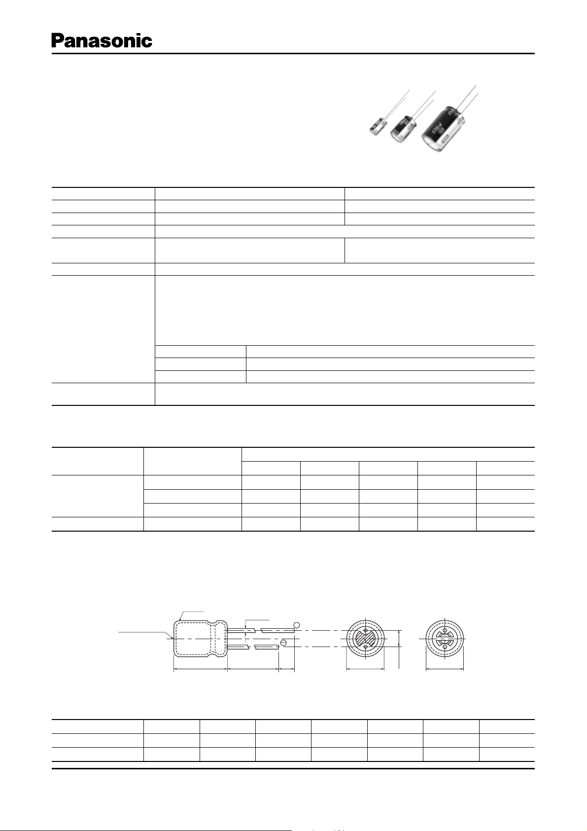
■ Di men sions in mm (not to scale)
[mm]
Pressure relief
φ6.3<
Sleeve
φd±0.05
+
–
✽
L
✽ L<16:L±1.0
L>20:L±2.0
14 min.
Body Dia. φD5 6.3 8 1012.516 18
Lead Dia. φd0.50.50.6 0.6 0.6 0.8 0.8
Lead space F 2.0 2.5 3.5 5.0 5.0 7.5 7.5
3 min.
φ5toφ8
φD±0.5
F±0.5
φ10<
φD±0.5
(mm)
Design and specifi cations are each subject to change without notice. Ask factory for the current technical specifi cations before purchase and/or use.
Should a safety concern arise regarding this product, please be sure to contact us immediately.
Apr. 2008
Page 2
Aluminum Electrolytic Capacitors/ NHG
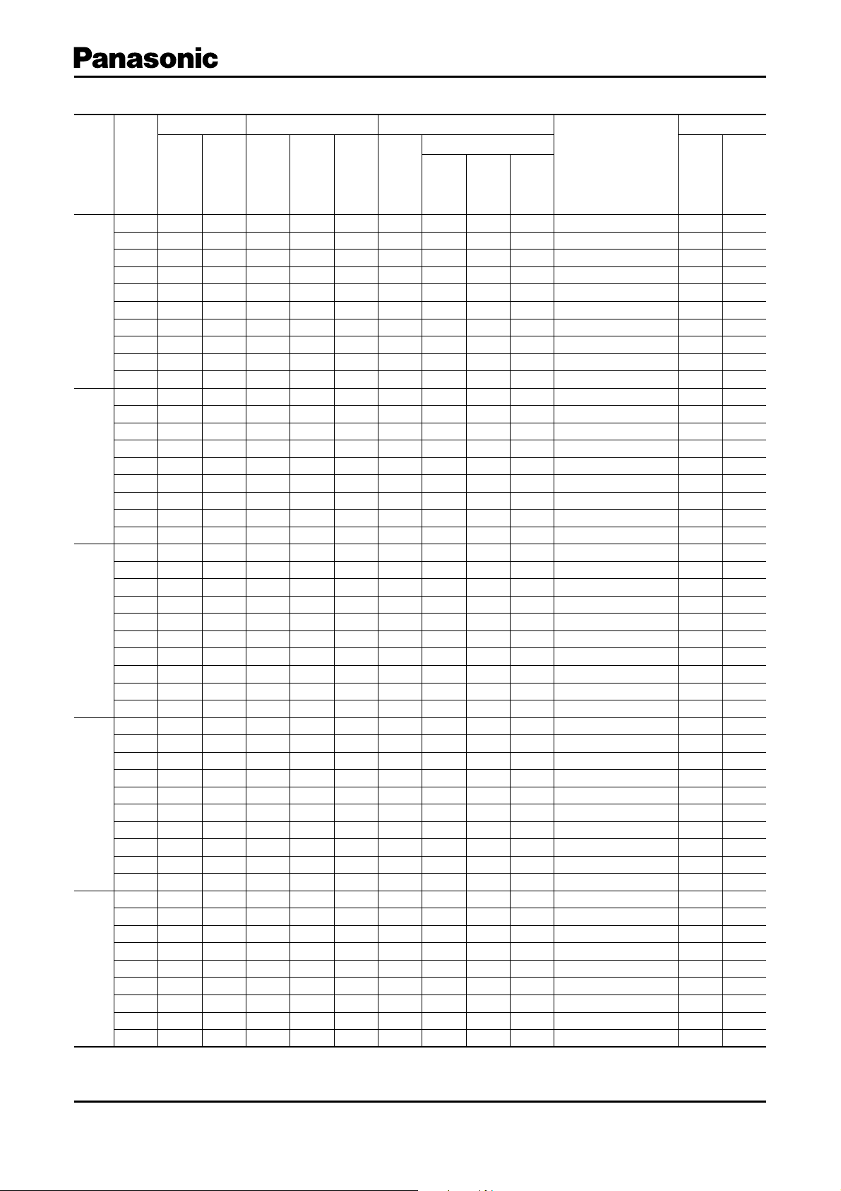
■ Standard Prod ucts
Case size Specifi cation Lead Length
W.V.
Cap.
(±20 %)
Dia. Length
Ripple
Current
(120 Hz)
(+105 °C)
(V) (µF) (mm) (mm)
(mA r.m.s.)
220 5 11 140 0.28 1000 0.5 2.0 5.0 2.5
470 6.3 11.2 2300.281000 0.5 2.5 5.0 2.5
1000 8 11.5 380 0.28 1000 0.6 3.5 5.0
2200 10 16 710 0.302000 0.6 5.0 5.0
3300 10 20 840 0.322000 0.6 5.0 5.0
6.3
4700 12.5 20 1090 0.34 2000 0.6 5.0 5.0
6800 12.5 25 1350 0.38 2000 0.6 5.0 5.0
10000 16 25 1650 0.46 2000 0.8 7.5 7.5
15000 16 31.5 2010 0.56 2000 0.8 7.5
22000 18 35.5 2350 0.70 2000 0.8 7.5
330 6.3 11.2 2000.241000 0.5 2.5 5.0 2.5
470 8 11.5 250 0.241000 0.6 3.5 5.0
1000 10 12.5 460 0.24 2000 0.6 5.0 5.0
2200 10 20 760 0.262000 0.6 5.0 5.0
10
3300 12.5 20 1000 0.28 2000 0.6 5.0 5.0
4700 12.5 25 1260 0.30 2000 0.6 5.0 5.0
6800 16 25 1570 0.34 2000 0.8 7.5 7.5
10000 16 31.5 1890 0.42 2000 0.8 7.5
15000 18 35.5 2180 0.52 2000 0.8 7.5
100 5 11 110 0 .2 0 1000 0.5 2.0 5.0 2.5
220 6.3 11.2 180 0.20 1000 0.5 2.5 5.0 2.5
330 8 11.5 260 0.201000 0.6 3.5 5.0
470 8 11.5 310 0.201000 0.6 3.5 5.0
1000 10 16 560 0.20 2000 0.6 5.0 5.0
16
2200 12.5 20 920 0.222000 0.6 5.0 5.0
3300 12.5 25 1170 0.24 2000 0.6 5.0 5.0
4700 16 25 1480 0.26 2000 0.8 7.5 7.5
6800 16 31.5 1780 0.30 2000 0.8 7.5
10000 18 35.5 2060 0.38 2000 0.8 7.5
47 5 11 91 0.161000 0.5 2.0 5.0 2.5
100 6.3 11.2 130 0.161000 0.5 2.5 5.0 2.5
220 8 11.5 230 0.161000 0.6 3.5 5.0
330 8 11.5 310 0.161000 0.6 3.5 5.0
25
470 10 12.5 380 0.16 2000 0.6 5.0 5.0
1000 10 20 680 0.16 2000 0.6 5.0 5.0
2200 12.5 25 1090 0.18 2000 0.6 5.0 5.0
3300 16 25 1400 0.20 2000 0.8 7.5 7.5
4700 16 31.5 1750 0.22 2000 0.8 7.5
6800 18 35.5 2040 0.26 2000 0.8 7.5
47 5 11 90 0.141000 0.5 2.0 5.0 2.5
100 6.3 11.2 150 0.141000 0.5 2.5 5.0 2.5
220 8 11.5 270 0.141000 0.6 3.5 5.0
330 10 12.5 350 0.14 2000 0.6 5.0 5.0
35
470 10 16 460 0.14 2000 0.6 5.0 5.0
1000 12.5 20 810 0.14 2000 0.6 5.0 5.0
2200 16 25 1260 0.16 2000 0.8 7.5 7.5
3300 16 31.5 1610 0.18 2000 0.8 7.5
4700 18 35.5 1910 0.20 2000 0.8 7.5
When requesting taped product, please put the letter "B" or "i" between the "( )". Lead wire pitch B=5 mm, 7.5 mm, i=2.5 mm.
The taping dimensions are explained on p.178 of our Catalog. Please use it as a reference guide.
tan
δ
(120 Hz)
(+20 °C)
Endur-
ance
Lead
Dia.
Lead Space
Straight
Tap i ng
B
✽
Tap i ng
i
✽
Part No.
(hours) (mm) (mm) (mm) (mm) (pcs) (pcs)
ECA0JHG221( )
ECA0JHG471( )
ECA0JHG102( )
ECA0JHG222( )
ECA0JHG332( )
ECA0JHG472( )
ECA0JHG682( )
ECA0JHG103( )
ECA0JHG153
ECA0JHG223
ECA1AHG331( )
ECA1AHG471( )
ECA1AHG102( )
ECA1AHG222( )
ECA1AHG332( )
ECA1AHG472( )
ECA1AHG682( )
ECA1AHG103
ECA1AHG153
ECA1CHG101( )
ECA1CHG221( )
ECA1CHG331( )
ECA1CHG471( )
ECA1CHG102( )
ECA1CHG222( )
ECA1CHG332( )
ECA1CHG472( )
ECA1CHG682
ECA1CHG103
ECA1EHG470( )
ECA1EHG101( )
ECA1EHG221( )
ECA1EHG331( )
ECA1EHG471( )
ECA1EHG102( )
ECA1EHG222( )
ECA1EHG332( )
ECA1EHG472
ECA1EHG682
ECA1VHG470( )
ECA1VHG101( )
ECA1VHG221( )
ECA1VHG331( )
ECA1VHG471( )
ECA1VHG102( )
ECA1VHG222( )
ECA1VHG332
ECA1VHG472
Min. Packaging Q'ty
Straight
Leads
Tap i ng
200 2000
200 2000
200 1000
200 500
200 500
200 500
200 500
100 250
100
50
200 2000
200 1000
200 500
200 500
200 500
200 500
100 250
100
50
200 2000
200 2000
200 1000
200 1000
200 500
200 500
200 500
100 250
100
50
200 2000
200 2000
200 1000
200 1000
200 500
200 500
200 500
100 250
100
50
200 2000
200 2000
200 1000
200 500
200 500
200 500
100 250
100
50
Design and specifi cations are each subject to change without notice. Ask factory for the current technical specifi cations before purchase and/or use.
Should a safety concern arise regarding this product, please be sure to contact us immediately.
Jul. 2008
Page 3

Aluminum Electrolytic Capacitors/ NHG
■ Standard Prod ucts
Case size Specifi cation Lead Length
W.V.
Cap.
(±20 %)
Dia. Length
Ripple
Current
(120 Hz)
(+105 °C)
(V) (µF) (mm) (mm)
(mA r.m.s.)
0.1 5 11 1.1 0.12 1000 0.5 2.0 5.0 2.5
0.22 5 11 2.3 0.12 1000 0.5 2.0 5.0 2.5
0.33 5 11 3.5 0.12 1000 0.5 2.0 5.0 2.5
0.47 5 11 5 0.12 1000 0.5 2.0 5.0 2.5
15 11 100.121000 0.5 2.0 5.0 2.5
2.2 5 11 18 0.12 1000 0.5 2.0 5.0 2.5
3.3 5 11 22 0.12 1000 0.5 2.0 5.0 2.5
4.7 5 11 26 0.12 1000 0.5 2.0 5.0 2.5
10 5 11 39 0.121000 0.5 2.0 5.0 2.5
50
22 5 11 65 0.121000 0.5 2.0 5.0 2.5
33 5 11 90 0.121000 0.5 2.0 5.0 2.5
47 6.3 11.2 110 0.12 1000 0.5 2.5 5.0 2.5
100 8 11.5 180 0.121000 0.6 3.5 5.0
220 10 12.5 300 0.12 2000 0.6 5.0 5.0
330 10 16 410 0.12 2000 0.6 5.0 5.0
470 10 2 0 530 0.12 2000 0.6 5.0 5.0
1000 12.5 25 950 0.12 2000 0.6 5.0 5.0
2200 16 31.5 1470 0.14 2000 0.8 7.5
3300 18 35.5 1770 0.16 2000 0.8 7.5
10 5 11 46 0.101000 0.5 2.0 5.0 2.5
22 5 11 71 0.101000 0.5 2.0 5.0 2.5
33 6.3 11.2 100 0.10 1000 0.5 2.5 5.0 2.5
47 6.3 11.2 120 0.10 1000 0.5 2.5 5.0 2.5
100 10 12.5 215 0.10 2000 0.6 5.0 5.0
63
220 10 16 335 0.10 2000 0.6 5.0 5.0
330 10 20 510 0.10 2000 0.6 5.0 5.0
470 12.5 20 640 0.10 2000 0.6 5.0 5.0
1000 16 25 930 0.10 2000 0.8 7.5 7.5
2200 18 35.5 1610 0.12 2000 0.8 7.5
0.47 5 11 9 0.08 1000 0.5 2.0 5.0 2.5
15 11 140.08 1000 0.5 2.0 5.0 2.5
2.2 5 11 21 0.08 1000 0.5 2.0 5.0 2.5
100
3.3 5 11 31 0.08 1000 0.5 2.0 5.0 2.5
4.7 5 11 38 0.08 1000 0.5 2.0 5.0 2.5
10 6.3 11.2 54 0.08 1000 0.5 2.5 5.0 2.5
22 6.3 11.2 93 0.08 1000 0.5 2.5 5.0 2.5
When requesting taped product, please put the letter "B" or "i" between the "( )". Lead wire pitch B=5 mm, 7.5 mm, i=2.5 mm.
The taping dimensions are explained on p.178 of our Catalog. Please use it as a reference guide.
tan
δ
(120 Hz)
(+20 °C)
Endur-
ance
Lead
Dia.
Lead Space
Straight
Tap i ng
B
✽
Tap i ng
i
✽
Part No.
(hours) (mm) (mm) (mm) (mm) (pcs) (pcs)
ECA1HHG0R1( )
ECA1HHGR22( )
ECA1HHGR33( )
ECA1HHGR47( )
ECA1HHG010 ( )
ECA1HHG2R2( )
ECA1HHG3R3( )
ECA1HHG4R7( )
ECA1HHG100( )
ECA1HHG220( )
ECA1HHG330( )
ECA1HHG470( )
ECA1HHG101( )
ECA1HHG221( )
ECA1HHG331( )
ECA1HHG471( )
ECA1HHG102( )
ECA1HHG222
ECA1HHG332
ECA1JHG100( )
ECA1JHG220( )
ECA1JHG330( )
ECA1JHG470( )
ECA1JHG101( )
ECA1JHG221( )
ECA1JHG331( )
ECA1JHG471( )
ECA1JHG102( )
ECA1JHG222
ECA2AHGR47( )
ECA2AHG010( )
ECA2AHG2R2( )
ECA2AHG3R3( )
ECA2AHG4R7( )
ECA2AHG100( )
ECA2AHG220( )
Min. Packaging Q'ty
Straight
Leads
Tap i ng
200 2000
200 2000
200 2000
200 2000
200 2000
200 2000
200 2000
200 2000
200 2000
200 2000
200 2000
200 2000
200 1000
200 500
200 500
200 500
200 500
100
50
200 2000
200 2000
200 2000
200 2000
200 500
200 500
200 500
200 500
100 250
50
200 2000
200 2000
200 2000
200 2000
200 2000
200 2000
200 2000
Design and specifi cations are each subject to change without notice. Ask factory for the current technical specifi cations before purchase and/or use.
Should a safety concern arise regarding this product, please be sure to contact us immediately.
Jul. 2008
Page 4

Aluminum Electrolytic Capacitors/ NHG
■ Standard Prod ucts
Case size Specifi cation Lead Length
W.V.
Cap.
(±20 %)
Dia. Length
Ripple
Current
(120 Hz)
(+105 °C)
(V) (µF) (mm) (mm)
(mA r.m.s.)
33 8 11.5 130 0.08 1000 0.6 3.5 5.0
47 10 12.5 165 0.08 2000 0.6 5.0 5.0
100 10 20 26 5 0.08 2000 0.6 5.0 5.0
100
220 12.5 25 440 0.08 2000 0.6 5.0 5.0
330 16 25 540 0.08 2000 0.8 7.5 7.5
470 16 25 715 0.08 2000 0.8 7.5 7.5
1000 18 35.5 985 0.08 2000 0.8 7.5
16.311.2 170.152000 0.5 2.5 5.0 2.5
2.2 6.3 11.2 25 0.15 2000 0.5 2.5 5.0 2.5
3.3 6.3 11.2 36 0.15 2000 0.5 2.5 5.0 2.5
4.7 6.3 11.2 43 0.15 2000 0.5 2.5 5.0 2.5
10 10 12.5 70 0.15 2000 0.6 5.0 5.0
160
22 10 20 130 0.15 2000 0.6 5.0 5.0
33 10 20 180 0.15 2000 0.6 5.0 5.0
47 12.5 20 220 0.152000 0.6 5.0 5.0
100 16 25 335 0.15 2000 0.8 7.5 7.5
220 16 31.5 540 0.15 2000 0.8 7.5
330 18 31.5 705 0.15 2000 0.8 7.5
16.311.2 170.152000 0.5 2.5 5.0 2.5
2.2 6.3 11.2 25 0.15 2000 0.5 2.5 5.0 2.5
3.3 6.3 11.2 36 0.15 2000 0.5 2.5 5.0 2.5
4.7 8 11.5 50 0.15 2000 0.6 3.5 5.0
200
10 10 16 80 0.15 2000 0.6 5.0 5.0
22 10 20 140 0.15 2000 0.6 5.0 5.0
33 12.5 20 190 0.152000 0.6 5.0 5.0
47 12.5 20 220 0.152000 0.6 5.0 5.0
100 16 25 335 0.15 2000 0.8 7.5 7. 5 2 .5
220 18 31.5 575 0.15 2000 0.8 7.5
16.311.2 170.152000 0.5 2.5 5.0 2.5
2.2 6.3 11.2 29 0.15 2000 0.5 2.5 5.0 2.5
3.3 8 11.5 42 0.15 2000 0.6 3.5 5.0
4.7 8 11.5 50 0.15 2000 0.6 3.5 5.0
250
10 10 16 88 0.15 2000 0.6 5.0 5.0
22 12.5 20 155 0.152000 0.6 5.0 5.0
33 12.5 20 190 0.152000 0.6 5.0 5.0
47 12.5 25 230 0.152000 0.6 5.0 5.0
100 16 31.5 365 0.15 2000 0.8 7.5
16.311.2 180.202000 0.5 2.5 5.0 2.5
2.2 8 11.5 31 0.20 2000 0.6 3.5 5.0
3.3 10 12.5 38 0.202000 0.6 5.0 5.0
4.7 10 16 50 0.20 2000 0.6 5.0 5.0
350
10 10 20 82 0.20 2000 0.6 5.0 5.0
22 12.5 20 130 0.202000 0.6 5.0 5.0
33 16 25 195 0.20 2000 0.8 7.5 7.5
47 16 25 230 0.2 0 2000 0.8 7.5 7.5
100 18 31.5 375 0.20 2000 0.8 7.5
When requesting taped product, please put the letter "B" or "i" between the "( )". Lead wire pitch B=5 mm, 7.5 mm, i=2.5 mm.
The taping dimensions are explained on p.178 of our Catalog. Please use it as a reference guide.
tan
δ
(120 Hz)
(+20 °C)
Endur-
ance
Lead
Dia.
Lead Space
Straight
Tap i ng
B
✽
Tap i ng
i
✽
Part No.
(hours) (mm) (mm) (mm) (mm) (pcs) (pcs)
ECA2AHG330( )
ECA2AHG470( )
ECA2AHG101( )
ECA2AHG221( )
ECA2AHG331( )
ECA2AHG471( )
ECA2AHG102
ECA2CHG010 ( )
ECA2CHG2R2( )
ECA2CHG3R3( )
ECA2CHG4R7( )
ECA2CHG100( )
ECA2CHG220( )
ECA2CHG330( )
ECA2CHG470( )
ECA2CHG101( )
ECA2CHG221
ECA2CHG331
ECA2DHG010 ( )
ECA2DHG2R2( )
ECA2DHG3R3( )
ECA2DHG4R7( )
ECA2DHG100( )
ECA2DHG220( )
ECA2DHG330( )
ECA2DHG470( )
ECA2DHG101( )
ECA2DHG221
ECA2EHG010 ( )
ECA2EHG2R2( )
ECA2EHG3R3
ECA2EHG4R7( )
ECA2EHG100( )
ECA2EHG220 ( )
ECA2EHG330( )
ECA2EHG470( )
ECA2EHG101
ECA2VHG010 ( )
ECA2VHG2R2( )
ECA2VHG3R3( )
ECA2VHG4R7( )
ECA2VHG100( )
ECA2VHG220( )
ECA2VHG330( )
ECA2VHG470( )
ECA2VHG101
Min. Packaging Q'ty
Straight
Leads
Tap i ng
200 1000
200 500
200 500
200 500
100 250
100 250
50
200 2000
200 2000
200 2000
200 2000
200 500
200 500
200 500
200 500
100 250
100
50
200 2000
200 2000
200 2000
200 1000
200 500
200 500
200 500
200 500
100 250
50
200 2000
200 2000
200 1000
200 1000
200 500
200 500
200 500
200 500
100
200 2000
200 1000
200 500
200 500
200 500
200 500
100 250
100 250
50
Design and specifi cations are each subject to change without notice. Ask factory for the current technical specifi cations before purchase and/or use.
Should a safety concern arise regarding this product, please be sure to contact us immediately.
Jul. 2008
Page 5

Aluminum Electrolytic Capacitors/ NHG
■ Standard Prod ucts
Case size Specifi cation Lead Length
W.V.
Cap.
(±20 %)
Dia. Length
Ripple
Current
(120 Hz)
(+105 °C)
(V) (µF) (mm) (mm)
(mA r.m.s.)
16.311.2 180.242000 0.5 2.5 5.0 2.5
2.2 8 11.5 30 0.24 2000 0.6 3.5 5.0
3.3 10 12.5 40 0.242000 0.6 5.0 5.0
400
4.7 10 16 50 0.24 2000 0.6 5.0 5.0
10 10 20 80 0.24 2000 0.6 5.0 5.0
22 12.5 25 145 0.242000 0.6 5.0 5.0
33 16 25 195 0.24 2000 0.8 7.5 7.5
47 16 31.5 250 0.24 2000 0.8 7.5
18 11.5 180.242000 0.6 3.5 5.0
2.2 10 12.5 29 0.24 2000 0.6 5.0 5.0
3.3 10 16 41 0.24 2000 0.6 5.0 5.0
450
4.7 10 20 49 0.24 2000 0.6 5.0 5.0
10 12.5 20 75 0.24 2000 0.6 5.0 5.0
22 16 25 115 0.24 2000 0.8 7.5 7.5
33 16 31.5 155 0.24 2000 0.8 7.5
When requesting taped product, please put the letter "B" or "i" between the "( )". Lead wire pitch B=5 mm, 7.5 mm, i=2.5 mm.
The taping dimensions are explained on p.178 of our Catalog. Please use it as a reference guide.
tan
δ
(120 Hz)
(+20 °C)
Endur-
ance
Lead
Dia.
Lead Space
Straight
Tap i ng
B
✽
Tap i ng
i
✽
Part No.
(hours) (mm) (mm) (mm) (mm) (pcs) (pcs)
ECA2GHG010 ( )
ECA2GHG2R2( )
ECA2GHG3R3( )
ECA2GHG4R7( )
ECA2GHG100( )
ECA2GHG220( )
ECA2GHG330( )
ECA2GHG470
ECA2WHG010 ( )
ECA2WHG2R2( )
ECA2WHG3R3( )
ECA2WHG4R7( )
ECA2WHG100( )
ECA2WHG220( )
ECA2WHG330
Min. Packaging Q'ty
Straight
Leads
Tap i ng
200 2000
200 1000
200 500
200 500
200 500
200 500
100 250
100
200 1000
200 500
200 500
200 500
200 500
100 250
100
Design and specifi cations are each subject to change without notice. Ask factory for the current technical specifi cations before purchase and/or use.
Should a safety concern arise regarding this product, please be sure to contact us immediately.
Jul. 2008
 Loading...