

Page 1

Matsushita
Programmable Controller FP-e
48 mm
Clearwater Tech - Phone: 800.894.0412 - Fax: 208.368.0415 - Web: www.clrwtr.com - Email: info@clrwtr.com
01/2004
Page 2

2
FP-e Series
The universal compact PLC
Clearwater Tech - Phone: 800.894.0412 - Fax: 208.368.0415 - Web: www.clrwtr.com - Email: info@clrwtr.com
01/2004
Do this, do that, do everything.
Timer
Time switch
Programmable
controller
● 3-color Display
Simple characters and numerical values
can be displayed. Simple messages as
well as timer/counter settings and
elapsed values can also be displayed.
● Built-in operation switch
Setting values can be changed. The
operation switch can also be used as an
input.
● Compact
Panel mountable, little space is taken up
on the control panel. The size is only 48 ×
48 × 70 mm (behind faceplate).
48
70
Temperature
controller
Hour meter
Counter
● Matches FP0 intelligence
(equivalent to FP0-C14)
● Panel mounted type
(in accordance with IP66,
IEC standard)
To match panel design,
a black faceplate is
available.
Same programming tools used as with the FP Series
One programming software for all PLC types
Programming software and cables are
common for all FP Series PLCs, so that
any program created for the FP Series
can be used by the FP-e as well.
FPWIN Pro Ver.5 and FPWIN GR
from Ver.2.3 offer a dialog to configure
the screen display of the FP-e easily.
You can check the result of the
configuration directly with the display
in the dialog.
Page 3
3
Optimised for a wide range of applications
FP-e Series
Clearwater Tech - Phone: 800.894.0412 - Fax: 208.368.0415 - Web: www.clrwtr.com - Email: info@clrwtr.com
01/2004
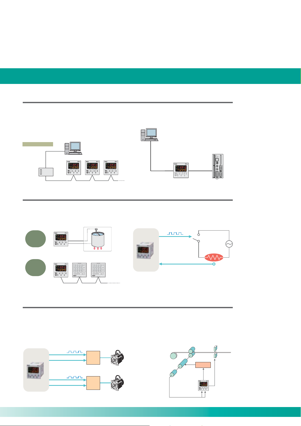
Equipped with RS485 and RS232C interfaces
● Up to 99 computer link stations are possible with
RS232C
(RS485 type)
Personal Computer
FP-e FP-e FP-e
RS485
RS485.
Up to 32 computer link stations are possible using a
C-NET adaptor and up to 99 are possible using a
commercially available adaptor. You can easily
monitor operation status or perform control.
Computer link
Commercially
available adaptor
Can even handle temperature control
● Two-point K-type thermocouple (-30 to 300°C)
connection is possible.
Can be used in place of a temperature controller or
used to control them.
As
temperature
controller
As
a controller for
temperature
controller
∗Compatible with MODBUS, it can be used as a slave.
(equipped with thermocouple input)
FP-e
FP-e
Temperature
controller, etc
RS485
PV
SV
SV1
Temperature
controller, etc
PV
OUT1
OUT2
SV
A1
EVT
TX/RX
SV2
SV1
AT
OUT
MODE
OFF
KT4
OUT1
OUT2
A1
EVT
TX/RX
SV2
AT
OUT
MODE
OFF
KT4
Up to 32
controllers
● With RS232C, communication with up to two ports
is possible.
(RS232C type)
Personal Computer
FP-e
RS232C RS232C
Tool port COM. port
Image Processing
Device, etc.
POWER
COM
CF
ERROR
FLA
COM.1
READY
COM
COM.2
TOOL
RDY
ERR
REN
STR
OVF
D1
D2
KEYPAD
D3
D4
D5
D6
D7
COM.1
CAMERA1
D8
COM
STA
COM
COM.2
FCT1
FCT2
ACK
TYP
IN1
MONITOR
CAMERA2
IN2
IN3
IN4
IN5
IN6
IN7
IN8
+
-
● PID instruction function
High-performance temperature control can be achieved
with PID instruction.
Y0
PID instruction
Heater
Thermocouple input
A0
Equipped with high-speed counter for support of 2-axis independent positioning
● Pulse output function
The unit comes equipped with 2 channels for pulse
output of up to 10 kHz pulses.
Since these two channels can be separately controlled,
the FP-e is also suitable for 2-axis independent
positioning.
Pulse output
Y0
CW/CCW output
Y2
Pulse output
Y1
CW/CCW output
Y3
Motor
driver 1
Motor
driver 2
Stepping motor
Servo motor
● High-speed counter function
In single phase, the 4-channel total is 10 kHz, and in 2phase the 2-channel total is 2 kHz total speed, making
the FP-e suitable for inverter control, etc.
(One half for the type with thermocouple input.)
Motor
Encoder
Feeder roller
START/STOP
signal
Input encoder
output into the
high-speed counter
Inverter
Cutter
Lead wire
and tape
Cutter blade
control signal
Page 4

4
FP-e Control Units
Decisive advantages in its class
Clearwater Tech - Phone: 800.894.0412 - Fax: 208.368.0415 - Web: www.clrwtr.com - Email: info@clrwtr.com
01/2004
FP-e Control Unit
New Age, Advanced Controller!
Timer, Counter, Hour Meter, Temperature Controller and PLC in one Unit
■ Features
1. 5-character, 2-line, 3-color Display
Simple characters and numerical values
can be displayed. Simple error messages
as well as operation instructions and
timer/counter set values can be
displayed.
2. Front Operation Switch
Timer/Counter set values can be
changed using front operation switches.
The switches can also be used as input
switches (X30 to X3F), so you need not
install external switches.
3. Equivalent to FP0-C14 Intelligence
of Small PLCs
In addition to the functions of
programmable controller FP0, pulse
output and high-speed counter functions
can be used. The unit comes equipped
with a tool port, and COM. port
(RS232C/RS485) for communication.
4. Easy Programming Using Wizard
Screen display instructions can be easily
created using a programming tool wizard
in FPWIN GR Ver. 2.3. or FPWIN Pro
Ver. 5.0.
■ Type
Name
FP-e
control
unit
Type Product No.
Standard type (RS232C)
Calendar timer type (RS232C)
Thermocouple input type (RS232C)
Standard type (RS485)
Thermocouple input type (RS485)
Calendar
timer
Not available
Available
Available
Not available
Not available
Thermocouple
input
Not available
Not available
Available
Not available
Available
COM.
port
RS232C
RS232C
RS232C
RS485
RS485
AFPE224300
AFPE224305
AFPE214325
AFPE224302
AFPE214322
5. Smooth Debugging
Monitoring memory area data and the I/O
status facilitates debugging using the R
(register) and I (I/O monitor) display
modes.
6. Panel Mounted Type
The front of a unit is water-proof (in
accordance with IP66, IEC standard).
■ Display modes and functions
1
N mode
1
(Normal mode)
N
PROG.
MODE
54321
1/2/SET
Displays characters and
numerical values, numerical
data can be changed.
FP-e
2
S mode
2
(Switch mode)
FP-e
S
PROG.
0
MODE
54321
1/2/SET
Can also display characters and
numerical values. Operation
switches can be used as inputs.
0
3
R mode
3
(Register mode)
PV
R
PROG.
MODE
54321
1/2/SET
Operation memory in the
controller can be monitored
and its data changed.
FP-e
0
4
I mode
4
(I/O monitor mode)
PROG.
MODE
1/2/SET
I/O status (X, Y) in the
controller can be
monitored.
I
54321
FP-e
0
Page 5

FP-e Series
Specification table
5
Clearwater Tech - Phone: 800.894.0412 - Fax: 208.368.0415 - Web: www.clrwtr.com - Email: info@clrwtr.com
01/2004
■ Performance specifications
Model
Item
Programming method/Control method
Number of
controllable I/O points
Program memory
Program capacity
Number of instruction
Operation speed
I/O update and Base time
Internal relay (R)
Special internal relay (R)
Relays
Timer/Counter (T/C)
points
Data register (DT)
Special data register (DT)
areas
Index registers (IX. IY)
Memory
Differential points
Master control relay points (MCR)
Number of labels (JP and LOOP)
Number of step ladders
Number of subroutines
Number of interrupt programs
Self-diagnostic function
Clock/calendar function
Battery life
Pulse catch input
Interrupt input
Note 3)
COM. port
Periodical interrupt
Constant scan
Password
High-speed counter function
* The combinations 1-phase × 2 ch.
and 2-phase × 1 ch. are also possible
for the high-speed counter.
Special functions Operation memory
Pulse
output function
PWM output
function
Timer
Counter
Note 7)
Counter
Internal relay
Data register
Memory backup
Note 1)
The proportion of timer points to counter points can be changed using a system register.
Note 2)
Precision of calendar timer:
- At 0°C/32°F, less than 200 seconds of error per month
- At 25°C/77°F, less than 70 seconds of error per month
- At 55°C/131°F, less than 240 seconds of error per month
Note 3)
When using the COM. port for communication, retransmission is recommended.
The RS232C driver IC for the COM. port conforms completely to EIA/TIA-232E and
CCITT V. 28 standards
Note 4)
The max. counting speed (10 kHz) is the counting speed with a rated input voltage of 24 V
DC and an ambient temperature of 25°C. The counting speed (frequency) will decrease
depending on the voltage and temperature.
Control unit
Front switch input
Built-in memory
Basic
High-level
Note 2)
Output points
Output frequency
Output points
Output frequency
Non-hold type
Hold type
Non-hold type
Hold type
Non-hold type
Hold type
AFPE224300
Standard type
(RS232C)
Relay symbol/Cyclic operation
14 points [Input: 8, Output: 6 (Tr. NPN: 5/Ry: 1)]
8 points
Built-in EEP-ROM
2,720 steps
83
117
0.9 µs/step (Basic instruction)
Typi cal 2 ms
1,008 points (R0 to R62F)
64 points (R9000 to R903F)
144 points (Initial setting: 100 timer points, T0 to T99/44 counter points, C100 to C143
Timer range (1 ms, 10 ms, 100 ms, 1 s): selected by instruction
1,660 words (DT0 to DT1659)
112 words (DT9000 to DT9111)
2 points
Unlimited number of points
32 points
64 labels
128 stages
16 subroutines
7 programs (external: 6, internal 1)
Watchdog timer, program syntax check, etc.
Not available
Not available
6 points in total (X0 and X1: 50 µs, X2 to X5: 100 µs)
RS232C RS485 RS232C RS232C RS485
0.5 ms to 30 s
Available
Available
Counter mode: Addition/subtraction (1-phase)
- Max. speed: 10 kHz (total of 4 ch.)
- Input contact: X0: count input (ch. 0), X1: count input (ch. 1), X2: reset input
X3: count input (ch. 2), X4: count input (ch. 3), X5: reset input
- Min. input pulse width: X0 and X1: 50 µs (10 kHz)
X3 and X4: 100 µs (5kHz)
Counter mode: 2-phase/individual/direction decision (2-phase) - Input points: 2 ch (Max.)
- Max. speed: 2 kHz (total of 2 ch.)
- Input contact: X0: count input (ch. 0), X1: count input (ch. 0), X2: reset input
X3: count input (ch. 2), X4: count input (ch. 2), X5: reset input
- Min. input pulse width: X0 and X1: 50 µs (10 kHz)
X3 and X4: 100 µs (5 kHz)
2 independent points (Y0 and Y1) (No interpolation function)
40 Hz to 10 kHz (Y0/Y1: 1-point)
40 Hz to 5 kHz (Y0/Y1: 2-point)
2 points (Y0 and Y1)
Frequency: 0. 15 Hz to 1 kHz Duty: 0.1 % to 99.9 %
Non-hold type: (all points)
From set value to C139
4 points (elapsed values) C140 to C143
976 points (R0 to R60F) 61 words (WR0 to WR60)
32 points (R610 to R62F) 2 words (WR61 to WR62)
1,652 words (DT0 to DT1651)
8 words (DT1652 to DT1659)
AFPE224302
Standard type
(RS485)
Note 6)
Note 5)
Note 6)
Note 7)
Note 8)
AFPE224305
Calendar timer type
(RS232C)
Available (year, month, day, hour, minute,
second and day of week). However, this can
only be used when a battery has been
installed.
220 days or more (actual usage value:
approx. 870 days (25°C). (Periodic
replacement interval: 1 year). (Value applies
when no power is supplied at all.)
Note 4)
- Input points: 4 ch. (Max.)
If the unit is equipped with both reset inputs X0 and X1, X2 serves as the reset input for X1.
If X3 and X4 are used, X5 serves as the reset input for X4.
When the positioning control instruction “F168” is performed, the maximum output
frequency is 9.5 kHz.
The program, system registers and the hold type area (internal relay, data register, and
timer/counter) are backed up by the built-in EEP-ROM.
When a battery is replaced with a new one in the FP-e unit with a calendar timer function,
settings can be changed without installing a battery. The data cannot be stored even when
the settings are changed using the system register.
F180 (SCR) and F181 (DSP) instructions are supported from Control FPWIN GR Ver. 2.2.
and FPWIN Pro V 4.1.
AFPE214325
Thermocouple input
type (RS232C)
12 points [Input: 6, Output: 6 (Tr. NPN: 5/Ry: 1)]
: 5 kHz (total of 4ch.)
Note 5)
Note 5)
X0 and X1: 100 µs (5 kHz)
: 1 kHz (total of 2ch.)
X0 and X1: 100 µs (5 kHz)
40 Hz to 5 kHz (1-point)
40 Hz to 2.5 kHz (2-point)
Thermocouple input
Note 1)
Not available
Not available
AFPE214322
type (RS485)
Page 6

6
FP-e Series
Technical data
p
Clearwater Tech - Phone: 800.894.0412 - Fax: 208.368.0415 - Web: www.clrwtr.com - Email: info@clrwtr.com
01/2004
■ General specifications
Item
Rated voltage
Operating voltage range
Allowed momentary power off time
Ambient temperature
Storage temperature
Ambient humidity
Storage humidity
Breakdown voltage
Insulation resistance
Vibration resistance
Shock resistance
Noise resistance
Operating condition
Current consumption
Protection
Mass
Description
24 V DC
21.6 to 26.4 V DC
10 ms
0 to +55°C
–20 to +70°C
30 to 85%RH (non-condensing)
30 to 85%RH (non-condensing)
Input terminals (COM, X0 to Xn)
Output terminals (Y0 to Y4)
Output terminal (Y5) Power supply terminal, Function earth
Input terminals (COM, X0 to Xn) Output terminals (Y0 to Y4) 500 V AC for 1 minute
Input terminals (COM, X0 to Xn)
Output terminals (Y0 to Y5)
Input terminals (COM, X0 to Xn) Output terminals (Y0 to Y5)
10 to 55 Hz, 1 cycle/min.
Double amplitude: 0.75 mm, 10 min. on X, Y, and Z axes
2
98 m/s
or more, 4 times on X, Y, and Z axes
1000V (p-p) with pulse widths 50 ns and 1 µs (based on in-house measurements)
Free from corrosive gases and excessive dust
200 mA or less (24 V DC)
IP66-compliant front section (Only when a rubber packing is used.)
Approx. 130 g
Power supply terminal, Function earth
Input terminal (A0, A1)
COM. (RS232C) terminal
Input terminal (COM, X0 to Xn, A0, A1)
COM. (RS232C) terminal
Power supply terminal, Function earth
Input terminal (A0, A1)
COM. (RS232C) terminal
500 V AC for 1 minute
1500 V AC for 1 minute
Min. 100 M
(measured with 500 V DC)
■ DC input specifications (X0 to X7)
Item
Number of input
Insulation method
Rated input voltage
Operating voltage range
Rated input current
Input points
per common
ON voltage/ON current
OFF voltage/OFF current
Input impedance
OFF to ON
Response
time
ON to OFF
Operating mode indicator
Note 1) X0 through X5 are inputs for the high-speed counter and have a fast response
time. If used as normal inputs, you should insert a timer in the program as
chattering and noise may be interpreted as an input signal.
Also, the above specifications apply when the rated input voltage is 24V DC
and the tem
8 points (6 points for thermocouple input type)
Optical coupler
24 V DC
21.6 to 26.4 V DC
Approx. 4.3 mA
8 points/common (6 points/common for
thermocouple input type)
Either the positive or negative of the input power
supply can be connected to common terminal.
19.2 V or less/4 mA or less
2.4 V or more/1 mA or more
Approx. 5.1 k (X0, X1)
Approx. 5.6 k (X2 to X7)
50 µs or less (X0, X1)
100 µs or less (X2 to X5)
2 ms or less (X6, X7)
50 µs or less (X0, X1)
100 µs or less (X2 to X5)
2 ms or less (X6, X7)
LCD display (I/O monitor mode)
erature is 25°C.
Description
Note 1)
Note 1)
Note 1)
Note 1)
■ Thermocouple input specifications
Item
Number of input
Te mperature sensor type
Input range
Accuracy
Resolution
Conversion time
Insulation method
Detection function of
wire disconnection
∗1) Temperature can be measured up to 330°C (626°F). When the measured temperature
exceeds 330°C (626°F) or the thermocouple wiring is disconnected, “K20000” is written
to the register.
∗2) Temperature conversion for thermocouple input is performed every 250 ms. The
conversion data is updated on the internal data register after the scan is completed.
∗3) The internal circuit and thermocouple input circuit are not insulated. Therefore, use the
nongrounding type thermocouples and sheath tubes.
2 points (CH0: WX1, CH1: WX2)
Thermocouple type K
–30.0 to 300.0°C
±0.5%FS±1.5°C (FS = –30 to 300°C)
0.1°C
250 ms/2CH
Between internal circuit and thermocouple input
circuit: noninsulated
Between CH0 and CH1 of thermocouple input:
PhotoMOS insulation
Available
Description
∗1)
∗2)
(–22 to 572°F)
∗3)
Page 7

FP-e Series
Technical data
7
Clearwater Tech - Phone: 800.894.0412 - Fax: 208.368.0415 - Web: www.clrwtr.com - Email: info@clrwtr.com
01/2004
■ Transistor NPN output specifications
(For Y0 to Y4)
Item
Insulation method
Output type
Rated load voltage
Operating load voltage range
Max. load current
Max. surge current
Output points per common
OFF state leakage current
ON state voltage drop
Response
time
External power
supply (For driving
internal circuit)
OFF to ON
ON to OFF
Current
Surge absorber
Operating indicator
Optical coupler
Open collector
5 to 24 V DC
4.75 to 26.4 V DC
0.5 A
1 A
5 points/common
100 µA or less
1.5 V or less
50 µs or less (For Y0 and Y1),
1 ms or less (For Y2,Y3 and Y4)
50 µs or less (For Y0 and Y1),
1 ms or less (For Y2,Y3 and Y4)
21.6 to 26.4 V DCVolt age
6 mA/point (For Y0 and Y1)
3 mA/point (For Y2, Y3, and Y4)
Zener diode
LCD display (I/O monitor mode)
Description
■ COM. port communication specifications
Item
COM. port type
Isolation status with
the internal circuit
RS232C
Non-isolated Isolated
Transmission distance 15 m 1200 m
Baud rate
∗3)
300, 600, 1200, 2400,
4800, 9600, 19200 bit/s
Communication method Half-duplex
Synchro system Synchronous communication method
Stop bit: 1 bit/2 bit
Parity: Not available/Available
Transmission format
(Odd number/Even number)
Data length 7 bit/8 bit
Beginning code: STX available/STX not available
Ending code: CR/CR+LF/not available/ETX
Data output order
No. of connected units
Starting from 0 bits per character
— 99
Communication mode
Description
∗2)
• General-purpose
communication
• Computer link
RS485
9600,19200 bit/s
∗5) ∗6)
■ Relay output specifications
(Y5)
Item
Output type
Rated control capacity
Output points per common
Response time
Life time
OFF to ON
ON to OFF
Mechanical
Electrical
Surge absorber
Operating indicator
Normally open (1 Form A)
2 A 250 V AC, 2 A 30 V DC
1 point/common
Approx. 10 ms
Approx. 8 ms
Min. 2 × 10
Min. 10
None
LCD display (I/O monitor mode)
∗1)
∗1) When communicating between FP-e and other devices, it is recommneded to perform
resend processing.
∗2) For RS232C wiring, be sure to use shielded wires for higher noise immunity.
∗3) Set the baud rate of RS485 with the FP-e system register and FP-e internal switch.
Set the baud rate of RS232C with the FP-e system register.
∗4) When sending a command from the FP-e is completed in RS485 communication, send a
response from the receiving device to the FP-e after the following time has elapsed:
9600 bit/s: 2 ms or longer 19200 bit/s: 1 ms or longer
∗4)
It takes at least 1 scan time (at least 2 ms) for the FP-e to send back a response after
received the command.
∗5) When our C-NET Adapter or RS485 device other than recommended is connected in the
system, the maximum connection number is limited to 32 units.
∗6) For a RS485 converter on the computer side, SI-35 (from LINE EYE Co., Ltd.) is
recommended.
When SI-35 is used in the system, up to 99 units can be connected.
19200 bit/s 9600 bit/s
Description
7
operations
5
operations (resistive load)
■ Dimensions ■ Wiring diagram
48 70
7.5
.
44.5
(mm)
● Input connector
(Standard type)
COM
X0
X1
X2
X3
X4
X5
X6
X7
● Output connector
+
−
L
Y0
L
Y1
L
Y2
Y3
L
Y4
L
YC
L
Y5
COM
Power
(Thermocouple input type)
TC0
TC1
(+)
Y0 to Y4
(−)
Y5
COM
COM
COM
X0
X1
X2
Xn
X3
X4
X5
A0+
A0−
● Power supply/COM. port connector
A1+
(RS232C type)
A1−
COM. port
(RS232C)
(RS485 type)
Internal circuit
(Terminal station) (Ordinary station)
24 V DC 24 V DC
Ground
COM. port
(RS485)
Internal circuit
24 V DC
Ground
Send data (Output)
Receive data (Input)
Signal Ground
+
−
Short
E
Ground
COM. port
(RS485)
Internal circuit
+
−
SD
RD
SG
+
−
E
Page 8

■ Options
FP-e Options
Backup battery
Included with calendar timer type
Part No.:
AFPG804
Rubber gasket
Included with unit
Part No.:
ATC18002
Mounting frame
Included with unit
Part No.:
AT8-DA4
Panel cover
Color: Black
Part No.:
AFPE803 (20 sets)
Protective cover
Part No.: AQM4803
Terminal socket set
4 type sockets, additional part
Part No.:
AFPE804
Programming tool software
Programming tool software
Control FPWIN Pro
Part No.: FPWINPROSEN5
(Small version, English manual)
FPWINPROSFR5
(Small version, French manual)
FPWINPROSDE5
(Small version, German manual)
FPWINPROFEN5
(Full version, English manual)
FPWINPROFFR5
(Full version, French manual)
FPWINPROFDE5
(Full version, German manual)
Control FPWIN GR
Part No.: FPWINGRF2 (Full version)
Programming cable
Part No.: AFC8513
Copyright © 2004 • Printed in Germany
4150 eu en 01/04
Please contact our Global Sales Companies in:
Europe
Europe Matsushita Electric Works (Europe) AG Rudolf-Diesel-Ring 2, D-83607 Holzkirchen, Tel. (08024) 648-0, Fax (08024) 648-111, www.mew-europe.com
Austria Matsushita Electric Works Austria GmbH Josef Madersperger Straße 2, A-2362 Biedermannsdorf, Tel. (02236) 2 6846, Fax (0 2236) 4 6133, www.matsushita.at
Benelux Matsushita Electric Works Benelux B.V. De Rijn 4, (Postbus 211), 5684 PJBest, (5680 AE Best), Netherlands, Tel. (0 499) 372727, Fax (0499) 372185, www.matsushita.nl or www.matsushita.be
France Matsushita Electric Works France S.A.R.L. B.P. 44, F-91371 Verrières le Buisson CEDEX, Tél. 01 60135757, Fax 01 60135758, www.matsushita-france.fr
Germany Matsushita Electric Works Deutschland GmbH Rudolf-Diesel-Ring 2, D-83607 Holzkirchen, Tel. (08024) 648-0, Fax (08024) 648-555, www.matsushita.de
Ireland Matsushita Electric Works UK Ltd. Irish Branch Office, Waverley, Old Naas Road, Bluebell, Dublin 12, Republic of Ireland, Tel: (01) 4600969, Fax: (01) 4601131, www.matsushita.ie
Italy Matsushita Electric Works Italia s.r.l. Via del Commercio 3-5 (Z.I. Ferlina), I-37012 Bussolengo (VR), Tel. (045) 6752711, Fax (045) 6700444, www.matsushita.it
Portugal Matsushita Electric Works España S.A. Portuguese Branch Office, Avda 25 de Abril, Edificio Alvorada 5-ºE, 2750-512 Cascais, Portugal, Tel. (21) 4828266, Fax (21) 4827421
Scandinavia Matsushita Electric Works Scandinavia AB Sjöängsvägen 10, 19272 Sollentuna, Sweden, Tel. (08) 59476680, Fax (08) 59476690, www.matsushita.se
Spain Matsushita Electric Works España S.A. Parque Empresarial Barajas, San Severo 20, 28042 Madrid, Tel. (91) 3293875, Fax (91) 3292976, www.matsushita.es
Switzerland Matsushita Electric Works Schweiz AG Grundstrasse 8, CH-6343 Rotkreuz, Tel. (041) 7997050, Fax (041) 7997055, www.matsushita.ch
United Kingdom Matsushita Electric Works UK Ltd. Sunrise Parkway, Linford Wood East, Milton Keynes, MK14 6LF, England, Tel. (01908) 231555, Fax (01908) 231599, www.matsushita.co.uk
North & South America
USA Aromat Corporation Head Office USA 629 Central Avenue, New Providence, N.J. 07974, Tel. 1-908-464-3550, Fax 1-908-464-8513, www.aromat.com
Asia
China Matsushita Electric Works Ltd. China Office 2013, Beijing Fortune, Building No. 5, Dong San Huan Bei Lu, Chaoyang District, Beijing, Tel. 86-10-6590-8646, Fax 86-10-6590-8647
Hong Kong Matsushita Electric Works Ltd. Hong Kong Rm1601, 16/F, Tower 2, The Gateway, 25 Canton Road, Tsimshatsui, Kowloon, Hong Kong, Tel. (852) 2956-3118, Fax (852) 2956-0398
Japan Matsushita Electric Works Ltd. 1048 Kadoma, Kadoma-shi, Osaka 571-8686, Japan, Tel. 06-6908-1050, Fax 06-6908-5781, www.mew.co.jp/e-acg/
Singapore Matsushita Electric Works 101 Thomson Road, #25-03/05, United Square, Singapore 307591, Tel. (65) 6255-5473, Fax (65) 6253-5689
(Asia Pacific) Pte. Ltd.
Matsushita Electric Works
Clearwater Tech - Phone: 800.894.0412 - Fax: 208.368.0415 - Web: www.clrwtr.com - Email: info@clrwtr.com
 Loading...