

Panasonic NA-F70H2, NA-F902H Service Manual

Service Manual
Fully Automatic Washing Machine
© Panasonic Appliances (Thailand) Co., Ltd. 2012.
All rights reserved. Unauthorized copying
and distribution is a violation of law.
(Revision : Mar. 2013)
Order No. PHAT100405C3
Product colour
Silver (A)
Destination
Indonesia, Vietnam, Malaysia
Singapore (Local), Singapore (Export)
India, Philippines, UAE (AFP)
Kuwait, Oman, Qatar
NA-F70H2
NA-F902H
There are special components used in this equipment which are important for safety. These parts are marked by in
the Schematic Diagrams, Circuit Board Diagrams, Exploded Views and Replacement Parts List. It is essential that these
This service information is designed for experienced repair technicians only and is not designed for use by the general
public. It does not contain warnings or cautions to advise non-technical individuals of potential dangers in attempting to
service a product. Products powered by electricity should be serviced or repaired only by experienced professional
technicians. Any attempt to service or repair the product or products dealt within this service information by anyone else
could result in serious injury or death.
critical parts should be replaced with manufacturer’s specified parts to prevent shock, fire or other hazards. Do not
modify the original design without permission of manufacturer.
WARNING
IMPORTANT SAFETY NOTICE

– 2 –
CONTENT
NA-F70H2 / F902H
Page
3
4
5
6
7
8
9
9
9
10
11
12
13
14 - 15
16
17
18
19
20
21
22
23
24
1. Attention in the repair work security
2. Specification
3. Features and Technical Information
3.1 Function Control with Fuzzy sensor
3.2 Power consumption and Current
4. Installation
4.1 Checking of placement
4.2 Connect the water supply hose
4.3 Install washing machine to steady
4.4 Child Lock program
5. Operations Panel
6. Wiring Diagram
7. Table of Errors
8. Troubleshooting
8.1 Table of troubleshooting
8.2 Symptoms are not trouble
9. Parts Exploded View and Replacement Parts List
9.1 Part Exploded View : Part A
9.2 Replacement Parts List : Part A
9.3 Part Exploded View : Part B
9.4 Replacement Parts List : Part B
9.5 Part Exploded View : Part C
9.6 Replacement Parts List : Part C
9.7 Part Exploded View : Packing
9.8 Replacement Parts List : Packing
10. Detail Change Notice

– 3 –
1. ATTENTION IN THE REPAIR WORK RECURITY
Please wear gloves when disassembling, replacing and assembling.
Always wear gloves to prevent an injury by the metal end face or an electric shock at the time
of the electricity service.
Please be careful to the edges of the metal end face.
Wear the working clothes of long sleeves to prevent an injury by the metal end face
or please work after covering the end face with tape or towel.
Rebuilding is prohibited.
Do not rebuild machine parts and
components when repairing service.
It may be the cause of damage or ignition.
Straightly pull out or insert in huasuton terminal.
Do not twist it. It may be the cause
of damage or ignition.
Be sure to use specified parts.
Always use specified parts for the parts with
mark in the electric circuit diagrams and
parts list. It may be the cause of smoke,
ignition or damage.
Do not touch any rotating object with hand unless it
stops completely.
Slow rotation may also roll in your hands
and cause injury.
Be careful about receiving an electric shock.
When doing electric connection service
such as voltage measurement, please
be careful enough about receiving an
electric shock at electric charging parts
and cable terminal parts.
Pull out electric plug when doing repair work.
Disassembling, assembling and replacing
parts should be done after pulling out
electric plug. Receiving an electric shock
or getting an injury may occur.
In order to prevent any accident during repair work and ensure security of the product after repair work, somethings
surely followed are explained below.
Connection of cables should be done according to regular work.
• Connection of cables should be tightened reliably with strength using solderless terminal.
(specified parts always using regular bonding plier)
• Install a fire protection cover (fireproof) covering connection area completely, and close
opening area by tape. (Please reuse the fire protection cover which came with the product.)
• When drawing cables around, fixing those cables with cable suppression part. Do not touch
rotating part, high temperature part and surface of metal.
• Be sure to replace with cable unit when any cable was snapped. When a part of the cable
unit was cut you must not do the connection repair. It may be the cause of smoke, ignition
or receiving an electric shock.
■Types of the contents being followed are classified by following figured symbols and explained.
(The following is an example of expression in pictures.)
Warning
Attention
Warning
Attention
This figured symbol means caution "Attention".
This figured symbol means must not do "Prohibition".
This figured symbol means surely execute "Instructions".
■The level of the arised damages or dangers, when indicated contents are ignored, are classified by following
indications and explained.
The content in the column of this indication is "Be assumed that possibly die or get seriously injured".
The content in the column of this indication is "Be assumed that possibly get damages or possibly only
damaged object occured".
NA-F70H2 / F902H

– 4 –
2. SPECIFICATION
NA-F70H2 / F902H
Model NA-F70H2 NA-F902H
Rate voltage
and Frequency
Rate Power
Consumption
(Wash / Spin)
Outer Dimention
Standard Capacity
Colour
Standard Water Consumption
Weight with accessories
Weight with packing
Pulsator with rated load (r.p.m.)
Spin Tub with rated load (r.p.m.)
Water Supply Pressure
Motor
Motor Power
Safety Switch
Water Inlet Hole
Fabric Softener Dispensor
Filter
Automatic Power - Cut Switch
Bleach Dispensor
400/205W
410/225W
460/282W
420/240W
7.0 Kg
7.0 Kg
Silver
130 Liter
31 Kg
35 Kg
Vietnam, Singapore (RBD)
Singapore (DBD), India
Philippines
Malaysia, UAE (AFP), Kuwait,
Qatar, Oman
520 mm. x 540 mm. x 650 mm.
563 mm. x 560 mm. x 945 mm.
110 r / min
730 r / min
0.03 to 1 MPa (0.3 to 10 Kgf / cm²)
Thermal Protector
Input : 320 Watts / Output : 180 Watts
Checking Unbalance / Tub Lid
Have
Have
Have
Have
Have
Indonesia
400/205W
7.0 Kg
7.0 Kg
Silver
130 Liter
31 Kg
35 Kg
220V/50Hz
230V/50Hz
230V/60Hz
240V/50Hz
220V/50Hz
230V/50Hz
230V/60Hz
240V/50Hz
Body
Installation
Wash
Spin
Water OnlyWash Level
Clothes Weight
56 Liters
45 Liters
35 Liters
25 Liters
18 Liters
16 Liters
High
Medium
Low 1
Low 2
Low 3
<Lower 3 Lower>
7.0 Kgs
3.5 Kgs
2.0 Kgs
1.0 Kgs
0.5 Kgs
0.3 Kgs
51 Liters
41 Liters
33 Liters
24 Liters
18 Liters
16 Liters
Standard Water Volume

– 5 –
3. FEATURES AND TECHNICAL INFORMATION
NA-F70H2 / F902H
Product special features
• Pre-wash weight sensor
• Dial indicating detergent level after sensing wash level
• Pre-set timer
• Fabric softener dispenser
• Detergent dispenser
• Automatic power-off when finish
• Dial indicating unusual sign (LED will blink)
• Overflow sensing device
• Dial indicating time remaining
High Medium Low
Low Pulse Number High
Weight Sensor
The weight is sensed by the moving force of the Pulsator, which
changes a capacitor pole and releases a signal wave. The wave
is changed into a pulse number from which the clothes weight is
sensed. Prior to weight sensing for Normal and Strong program,
the machine runs without water by spinning the Pulsator to left
and right for 4.2 seconds (ON 0.3 second- OFF 0.4 second).
The motor stops (OFF), a water system counts the pulse
number, then calculates the accumulated pulse numbers for
drawing water into the tub over a defined level. The dial will
indicate High wash level.
Program Time
Normal
Mini
Speedy
Blanket
Delicate
Tub Hygiene
Approx. 40-59 min
Approx. 15 min
Approx. 37-53 min
Approx. 47-55 min
Approx. 23 min
Approx. 150 min

– 6 –
NA-F70H2 / F902H
3.1 Function Control with Fuzzy sensor
Clothes quantity checking, wash level indication and detergent consumption indication with Fuzzy Logic System.
1. Check clothes quantity and specify the amount of detergent
1. Wash timer and spin timer with checked clothes quantity
2. Additional wash timer and spin timer as temperature increases
<Motor status>
Turn Switch “ON”
Press “Start” button
1. Check clothes quantity
2. Check ambient
temperature
A. Check clothes
quantity
B. Control wash time
C. Control spin time
Supply water to a proper
level
WASH
RINSE
SPIN
Switch will automatically
cut the power current
“OFF”
Spintimer +0 min. +1 min. +2 min. +0 min.
Wash Timer +0 min. +2 min. +3 min. -1 min.
External temp. 25°C 15°C 5°C 30°C
High
3.0 Kg and more
Medium
1.2 Kg~3.0 Kg
Low
0 Kg~1.2 Kg
Wash Timer 12 min. 12 min. 9 min.
Spin Timer 6 min. 6 min. 5 min.
2. Temperature checking
Check temperature in the atmosphere when the machine starts.
In case of low temperature, wash timer and spin timer are extended
automatically so that washed clothes are as clean as washing in
high temperature.
<Checking Method>
Check cross pressure at the
capacitor while the Pulsator operates
without water.
Rotate clockwise
stop
Rotate
anti-clockwize
stop
Rotate clockwise
stop
Rotate
anti-clockwize
stop
Rotate clockwise
stop
Rotate
anti-clockwize
stop

– 7 –
NA-F70H2 / F902H
The following requirements shall be met in accordance with Product Standard.
Noted : To determine the valve, integrate the data for 3 min. after 3 min. from starting motor and covert based
on duty ratio of water flow for that period.
(1) Washing
3.2
Power consumption and current
(2) Spinning
Voltage Frequency
220V 50Hz
230V 50Hz
240V 50Hz
230V 60Hz
Power source
Current (A)
Power consumption
(W)
Current (A)
Power consumption
(W)
Current (A)
Power consumption
(W)
Current (A)
Power consumption
(W)
Water load Rated load
1.28 - 2.02
257 - 360
1.30 - 2.04
266 - 371
1.26 - 1.99
275 - 372
1.52 - 2.37
310 - 426
1.78 - 2.22
357 - 440
1.80 - 2.24
366 - 451
1.76 - 2.19
375 - 462
2.02 - 2.57
410 - 506
Voltage Frequency
220V 50Hz
230V 50Hz
240V 50Hz
230V 60Hz
Power source
Current (A)
Power consumption
(W)
Current (A)
Power consumption
(W)
Current (A)
Power consumption
(W)
Current (A)
Power consumption
(W)
Water load Rated load
0.72 - 1.02
168 - 225
0.78 - 1.10
185 - 247
0.78 - 1.11
199 - 264
1.10 - 1.50
236 - 310
0.82 - 1.02
183 - 225
0.80 - 1.10
200 - 247
0.88 - 1.11
214 - 264
1.20 - 1.50
251 - 310
– 8 –
NA-F70H2 / F902H
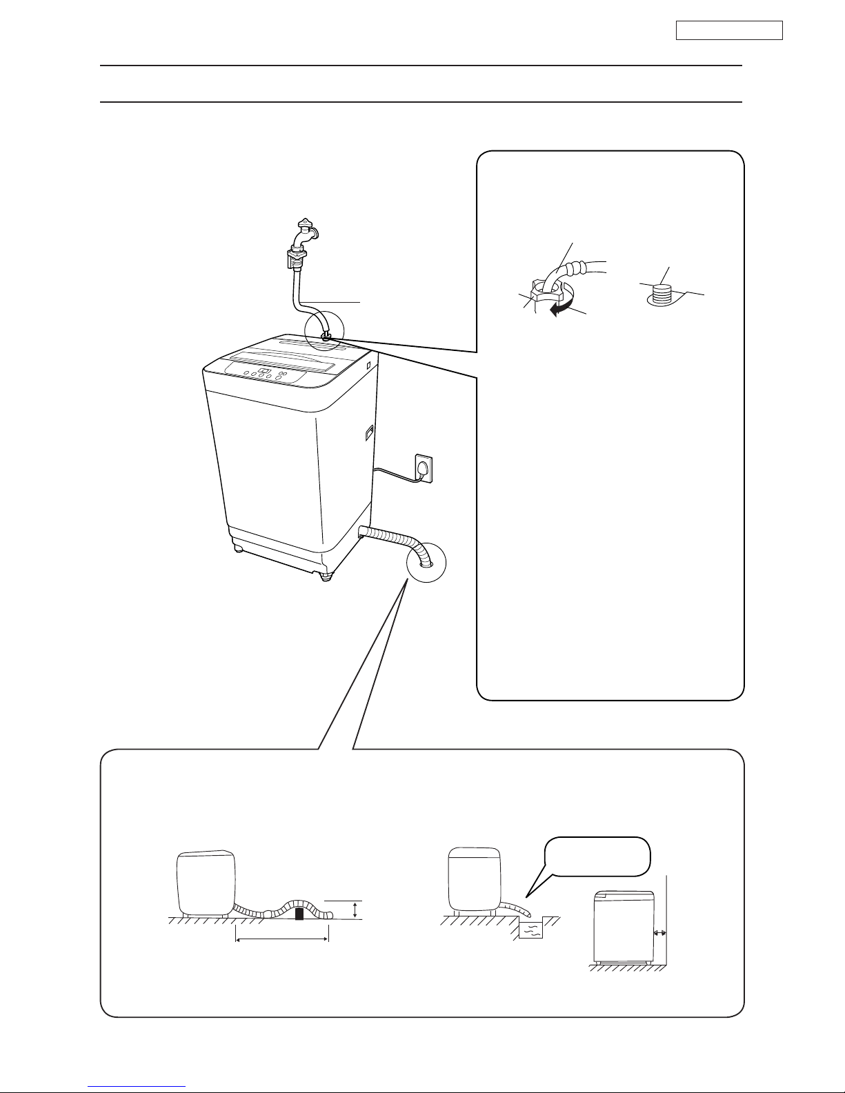
4.1 Checking of placement
4. INSTALLATION
Water Supply
Hose
Drain hose
Connect the water supply hose
to the water supply valve screw.
[Cautions]
Hose extension
Elbow
Water supply
valve screw
Nut
If extended external part is necessary when connecting the drain hose, the length of the drain hose should be less
than 3 m and the height should be below 10 cm.
3 m max.
Do not put hose tip
under the water
Over 10 cm
Install the machine 10 cm or more away from the wall.
Good Example
Below 10 cm
1. Push the water supply hose nut straights onto
the water supply valve screw.
2. Hold the elbow by lifting it up, screw the nut
onto the water supply valve screw, and firmly
tighten the nut.
3. After the nut is tightened, check whether or
not the elbow is unsteady or loose.
4. After tightening, open the faucet to confirm
that there is no water leakage.
Firmly tighten the nut, otherwise water leakage
will result.
Water Pressure Rating :
2.9 x 10 ~ 9.8 x 10 Pa
45
 Loading...