

Panasonic MN6474A Datasheet
For Audio Equipment
MN6474A
D/A Converter for Digital Audio Equipment
Overview
The MN6474A is a CMOS digital-to-analog converter
with a built-in 16-bit digital filter for pulse code
modulation (PCM) digital audio equipment.
It uses noise shaping technology to convert a digital
signal into a PWM signal.
It contains a 4-fold oversampling digital filter that
permits simplification of the low pass filter after the D/A
converter, thus greatly reducing the power consumption
of the entire D/A conversion system.
The chip provides both regular and inverted phase
outputs for both channels.
The chip contributes to cost and size reductions for CD
players and other digital audio equipment.
Features
Built-in 4-fold oversampling digital filter
(ripple of only ±0.0072 dB within the supported
band and attenuation of 62.7 dB within the cutoff
band)
Internal resolution of 18 bits
Two's complement input (I2S input code also supported)
Built-in overflow limiter
No zero cross distortion
Sample-and-hold circuit is unnecessary
Output pin for detecting zero input
Single 5V power supply
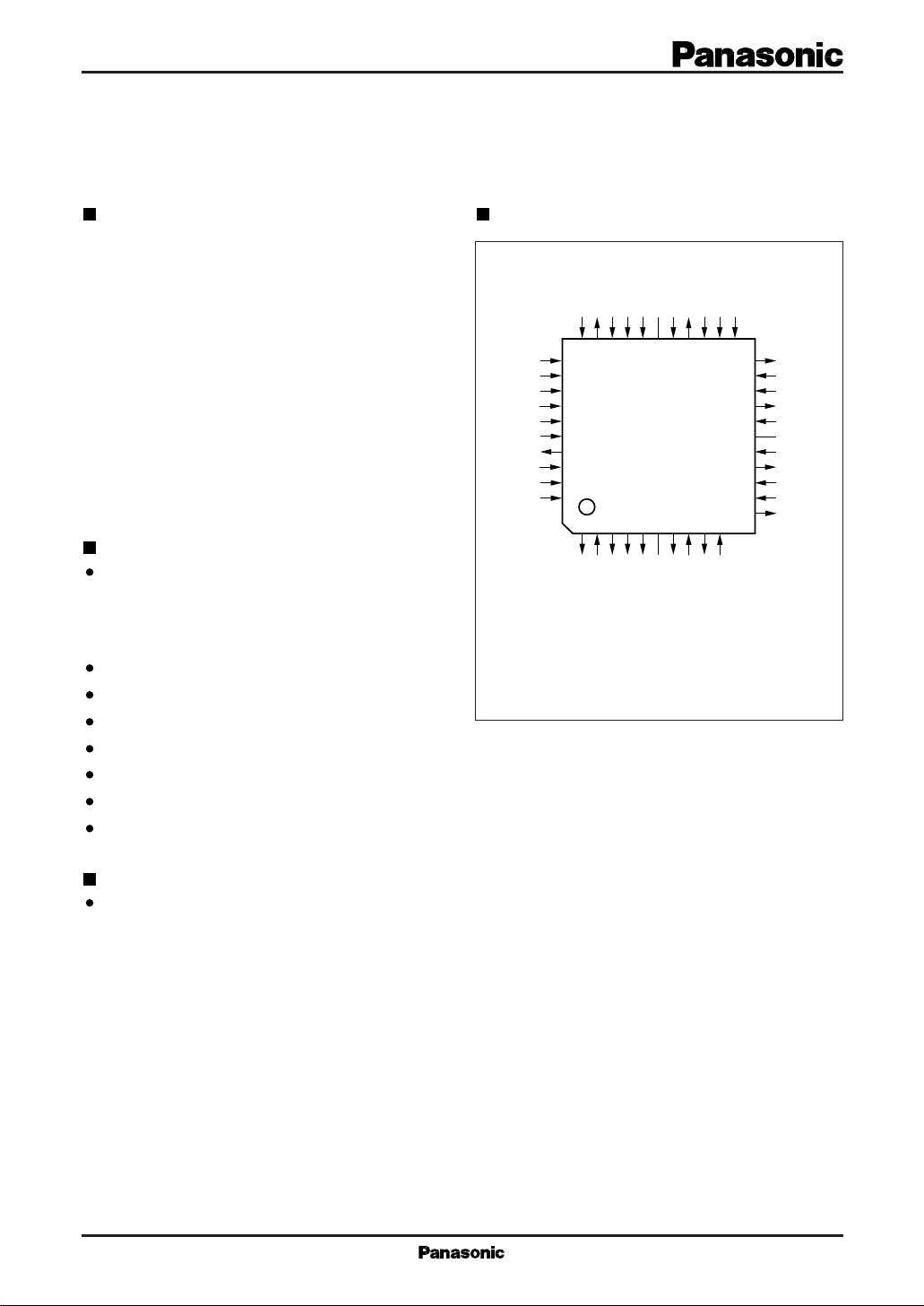
Pin Assignment
192FS
ZFLGB
3231302928272625242322
SS3
PD
33
34
35
36
37
38
DD
39
40
41
42
123456789
MLD
RSTB
QFP042-P-1414A
LRPOL
LRCLK
BCLK
SRDATA
DV
DV
384FS
MDATA
MCLK
SS2DVDD2
NSUB
DV
N.C.X1X2
IE
TP1
TP2
TEST1
TEST2
(TOP VIEW)
N.C.
SS1DVDD1AVDD1
DV
10
DD4
N.C.
AV
21
OUTR(–)
20
AV
19
18
17
16
15
14
13
12
11
SS1
AV
SS2
OUTR(+)
AV
DD2
N.C.
AV
DD3
OUTL(+)
AV
SS3
AV
SS4
OUTL(–)
Applications
CD players and other digital audio equipment
MN6474A For Audio Equipment
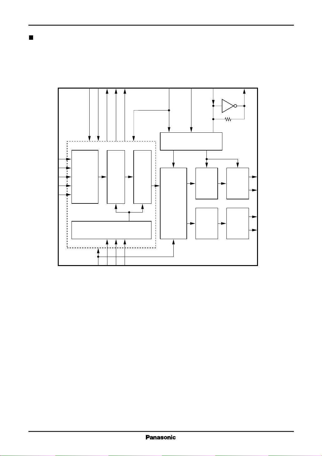
Block Diagram
LRPOL
LRCLK
BCLK
SRDATA
Analog
Block
(R)
Analog
Block
(L)
X2
25
21
18
14
11
OUTR
OUTR
OUTL
OUTL
(–)
(+)
(+)
(–)
ZFLGB
TP1
TP2
TEST1
TEST2
7
6
5
4
31
33
34
S/P
35
Converter
36
3
IE
Microcomputer Interface
FIR 1 FIR 2
40PD41
42
1
384FS
39
Timing Generator
Noise
Shaping
Logics
192FS
32
X1
26
PWM
Logics
(R)
PWM
Logics
(L)
MCLK
MDATA
MLD
 Loading...