

Panasonic MIR-H163-PA, MIR-H163-PT, MIR-H163-PC, MIR-H163-PK, MIR-H263-PA Service Manual
...
Service Manual
Heated Incubator
MIR-H163
Panasonic Healthcare Co., Ltd.
Biomedical Division
MIR-H263
SM9910316

Effective models
This service manual is effective for following models.
Model name
Voltage
Frequency
Plug Type
MIR-H163-PA
115V
60Hz
U3
MIR-H163-PC
220V
50Hz
G3L
MIR-H163-PE
230/240V
50Hz
K3
MIR-H163-PK
220V
50/60Hz
K3
MIR-H163-PT
110V
60Hz
J3
Model name
Voltage
Frequency
Plug Type
MIR-H263-PA
115V
60Hz
U3
MIR-H263-PC
220V
50Hz
G3L
MIR-H263-PE
230/240V
50Hz
K3
MIR-H263-PK
220V
50/60Hz
K3
MIR-H263-PT
110V
60Hz
J3
MIR-H263-PR
220V
60Hz
M3

Contents
Page
Feature and Caution
------------------------------------------------
1
Specifications
------------------------------------------------
2
- Structural s p ec if ications
- Control spec if ic ations
- Performanc e s pec ifications
Dimensions
------------------------------------------------
4
Wiring Diagram
------------------------------------------------
6
Circuit Diagram
------------------------------------------------
7
Control specifications
------------------------------------------------
8
Test Data
------------------------------------------------
15
- Temperatur e Control Sp e c i f i c ation
- Temperatur e Accuracy
- Temperatur e F luctuation R ange
- Temperatur e Distribution
Instruction manual
------------------------------------------------
18

Features
1. Chamber Temperature Adjustment
It is capable of cultivating the bacteria that prefer from medium temperature to high
temperature.
- Constant temperature environment by microcomputer PID control + air jacket (natural
convection)
- Achieve constant temperature environment with high accuracy that temperature
fluctuation is within ±0.2℃ (set temp. 37℃, center in chamber)
- Temperature setting range: room temperature +5℃~80℃ (ambient temperature 20℃)
2. Alarm and Safety Function
- Temperature alarm: when the temperature deviated ±2.5℃ from set value
(Lamp, Buzzer)
- Overheat Protection: the heater is OFF when the temperature exceeds the upper limit.
- Overcurrent breaker combined power switch
- Key lock switch
- Memory backup: store the settings even after the power supply is OFF
- Self-diagnosis function: display errors and shutdown when any abnormality is detected,
such as sensors, etc.
3. Usability
- Microcomputer timer function: auto start, auto stop and set time announcement
- Stainless for whole interior with excellent chemical resistance and durability
- Latch integrated door handle that makes door opening easier by one hand
* Above features follow the previous models MIR-162/262 and there is no change.
Caution
* Parts replacement and option unit installation must be done by trained serviceman.
* Serviceman must refer to the section “Electric parts” and “Cooling unit parts”
about the parts for those operation.
-1-
Specifications
■ Structural Specifications
Product Name
Heated Incubator
Model
MIR-H163
MIR-H263
External dimensions
W580 mm x D595 mm x H820 mm
W730 mm x D645 mm x H870 mm
Internal dimensions
W450 mm x D460 mm x H450 mm
W600 mm x D510 mm x H500 mm
Effective capacity
93 L
153 L
Exterior
Painted steel
Interior
Stainless steel plate (SUS 304)
Outer door
Painted steel
Inner door
Tempered glass
Shelf
2 shelves,
Stainless steel wire with frame,
W415mm x D425mm,
Maximum load: 15kg, Multistage adjustable
3 shelves,
Stainless steel wire with frame,
W565mm x D475mm,
Maximum load: 15kg, Multistage adjustable
Insulation
Glass wool
Heater
200W
300W
Timer
Auto start, Auto stop, Operation time announcement 00:00~99:99 (H:M)
Temperature sensor
Thermistor
Power supply switch
Over current breaker: 10A
Weight
50 kg
67 kg
Accessories
2 stainless shelves
3 stainless shelves
Options
Stand: MCO-50T
Stand: MKD-300T
Double stack stand: MKD-150T
Country of origin
Indonesia
■ Functions
Model
MIR-H163
MIR-H263
Temperature
Setting range
Room temperature +5℃~80℃ (set in unit of 0.1℃)
Distribution
Within ±1℃ (set temp.: 37℃, AT: 20℃, no load)
Fluctuating
range
±0.2℃ (set: less than ~60℃, AT: 20℃, no load)
±0.5℃ (set: 60℃~80℃, AT: 20℃, no load)
Control
Microcomputer PID control + Air jacket (natural convection)
Display
Digital display (set in unit of 0.1℃)
Timer function
■ Delay timer (auto start)
Start operation after set time passed from pressing start key
■ Timer mode
- Normal mode (auto stop): Heater is OFF after set time passed
- Timer mode C: Buzzer sound come out after set time passed, but it
continues normal operation
Memory backup
Operation program backup (non-volatile memory)
-2-
■ Alarm/Safety Functions
Types
Condition
Display
Buzzer
Action Taken
Auto set
upper/lower
limit alarm
Temp. deviated ±2.5℃ from set
value
Alarm lamp lighting
Temp. display
blinking
After 3sec.
intermittently
――
Auto return
No key operation for about
45 sec. in each setting mode
Display current value
――
Finish
setting mode
Key lock switch
Key lock becomes ON
―――
――
Not accept any
key input except
call key
Temp. sensor
abnormal
Temp. sensor open or short circuit
Alarm lamp lighting
E01 blinking
Intermittently
Stop operation
Triac abnormal
Triac open circuit
Alarm lamp lighting
E02 blinking
Intermittently
Stop operation
Triac short circuit
Alarm lamp lighting
E03 blinking
Intermittently
Stop operation
Relay
abnormal,
etc.
Relay short circuit
Alarm lamp lighting
E04 blinking
Intermittently
Stop operation
Relay open circuit, heater short
circuit or temp. around PCB is
65℃ or more
Alarm lamp lighting
E05 blinking
Intermittently
Stop operation
Overheat
protection
During
OFF
Abnormal heating is
detected, safety
circuit operates by
independent temp.
sensor
Display no change
Continuously
Stop operation
forcibly by
external circuit
During
ON
Alarm lamp lighting
E05 blinking
Continuously
(Intermittently
when temp.
drops)
Stop operation
forcibly by
external circuit
● Buzzer sound during overheat protection cannot be stopped by buzzer stop key (BZ). Turn off the main switch.
■ Performance Specification
Product Name
Heated Incubator
Model
MIR-H163
MIR-H263
Temperature control
range
Room temp. +5℃~60℃ (AT: 0℃~ less than 20℃, no load)
Room temp. +5℃~80℃ (AT: 20℃~35℃, no load)
Temperature distribution
±1℃ (set: 37℃, AT: 20℃, no load)
Temperature fluctuation
range
±0.2℃ (set: less than 60℃, AT: 20℃, no load)
±0.5℃ (set: 60℃~80℃, AT: 20℃, no load)
Maximum current
2.0 A
3.0 A
Maximum power
consumption
200 W
300 W
Maximum heat
discharge
720 kJ/h
1080 kJ/h
Applicable environment
condition
Temperature: 0℃~35℃, Humidity: 80%R.H. or less
- Each data is measured based on our standards.
- Specification can be changed for improvement without notification.
-3-
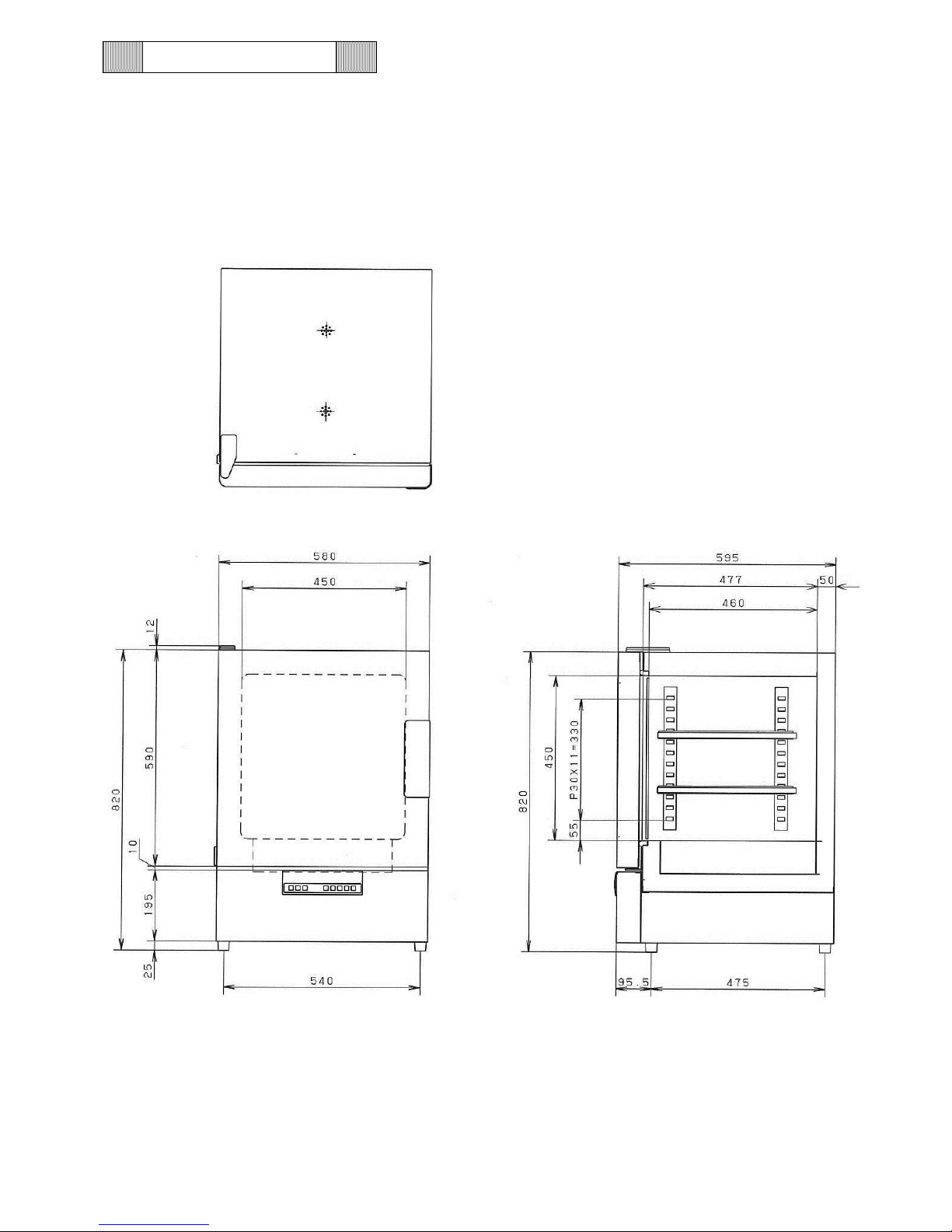
Dimensions
MIR-H163
-4-
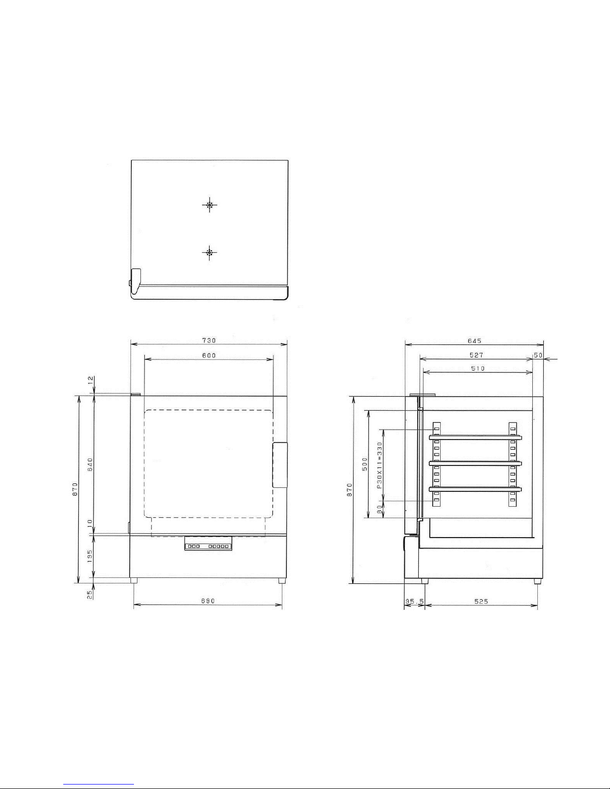
MIR-H263
-5-
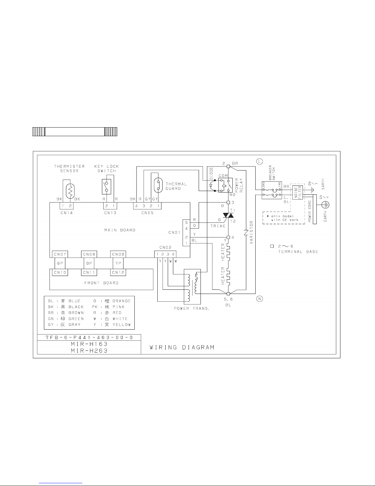
MIR-H163/H263
Wiring Diagram
-6-
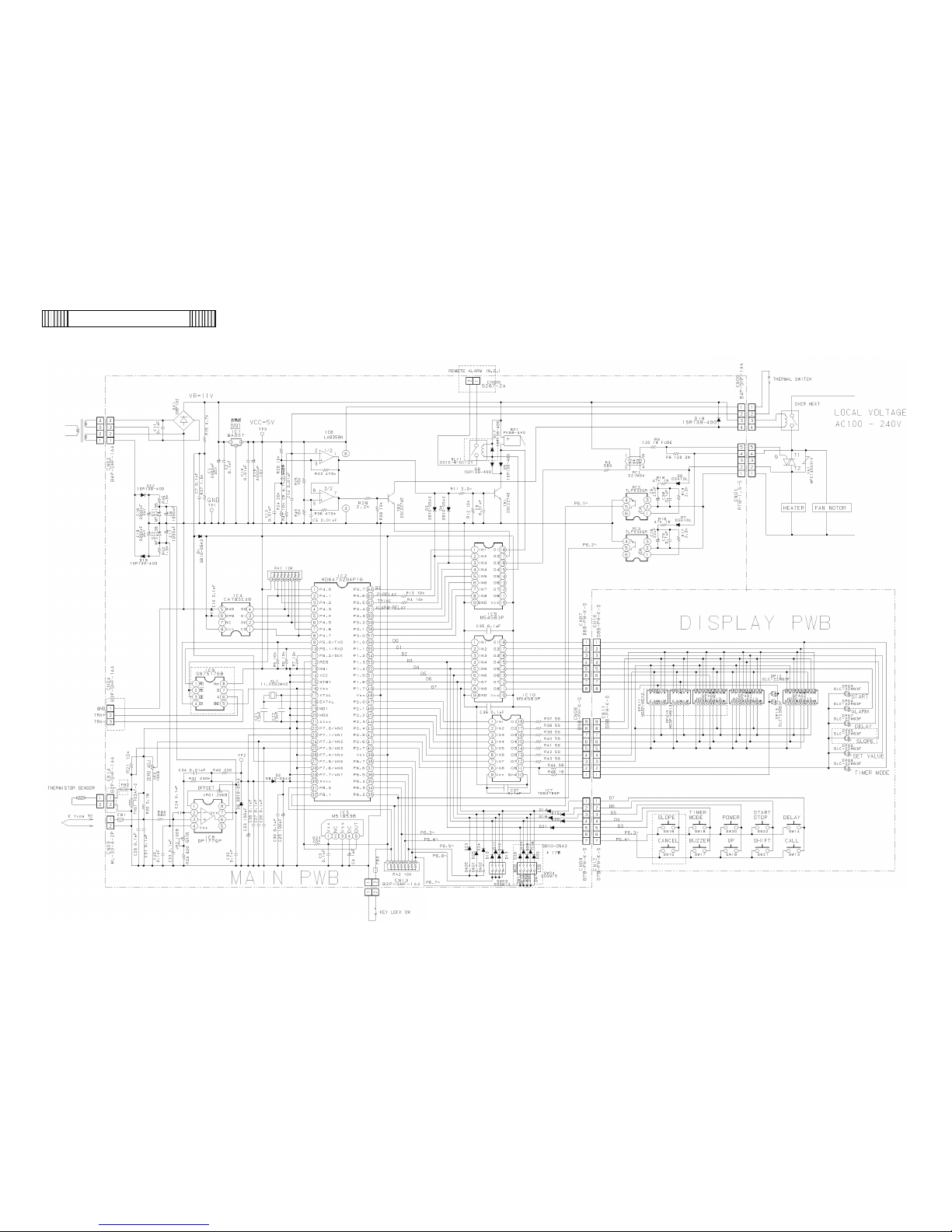
MIR-H163/H263
Circuit Diagram
-7-

Control Specifications
1. Keys on Control Panel
BZ (Alarm stop key)
To stop buzzer during intermittent buzzer is sounding (auto set
temperature alarm).
If this key is pressed again after buzzer is stopped, intermittent
buzzer does not sound again.
Even if this key is pressed when displayed numbers are not blinking,
buzzer does not sound.
CALL (Call key)
Not in operation
In operation
In function
setting mode
: Set temperature, set time and chamber
temperature are displayed in turn by
pressing CALL key.
: Remaining time, set temperature, set time
and chamber temperature are displayed in
turn by pressing CALL key.
: Accept function code and data.
Press the key during temperature or time
setting mode, store the set value and return
to chamber temperature display.
Numerical Shift Key
(UP key)
Increase each digit value by 1 during setting mode.
Keep pressing for about 5 seconds when chamber temperature
is displayed to show F00 and become function code input mode.
(use UP key and SHIFT key to input function code and press
CALL key to enter input function mode.)
Digit Shift Key
(SHIFT key)
Shift blinking digit from left to right during setting mode. Shifted
digit is different based on set data.
POWER
(Power switch)
Power switch to turn ON/OFF for control panel.
Press this key when there is no display at numerical value displayed
area after power switch is ON (only POWER key is acceptable) to
show chamber temperature and make other keys acceptable.
Press this key again to return “no display” condition.
Press this key during operation to stop operating and move to “no
display” condition.
Press this key during temperature or time setting, store the set value
and move to “no display” condition.
-8-

DELAY
(Delay timer key)
Press this key to delay operation start.
Press this key at set delay time display, clear set delay time.
Press this key again afterwards, store new set value and return to
chamber temperature display.
Press CALL key after DELAY key is pressed 3 times during
temperature or operation timer setting, store the set value.
TIMER MODE
(Timer mode select key)
To select timer mode (normal mode or timer mode C).
START/STOP
To start operation during setting mode.
If delay time is set, start after delay time is passed (start is not
acceptable during delay time setting mode).
To stop operation during operation.
Press this key during temperature or time setting, store the set
value and start operation.
2.
Temperature Setting
Setting Range:
Ambient temp. +5℃~60℃ (Ambient temp. is 0℃~less than 20℃)
Ambient temp. +5℃~80℃ (Ambient temp. is 20℃~35℃)
Leave it as it is for about 45 seconds during temperature setting,
return to chamber temperature display (auto return function). Set
value is stored.
Setting cannot be changed during operation (Digit shift key and
Numerical value shift key are not acceptable).
Zero Adjustment:
VR3 can be zero adjustment in F07. Adjusted range is ±6.5℃.
In F11, adjusted range is ±19.9℃.
3.
Time Setting
Setting range:
00:01~99:59 Press CALL key to store.
Change the digit value of multiples of 10 by Numerical value shift key,
“_:_” is displayed after “9” and then “00:00” is displayed.
If press CALL key with “00:00”, buzzer sounds and return to chamber
temperature display, but set value is not changed.
Setting cannot be changed during operation.
-9-

4.
Auto Set Temperature
Alarm
Condition of alarming:
When chamber temperature (TEMP.PV) is deviated more than
±2.5℃ from current set value (TEMP.SV).
Action:
Blinking all digits in temperature display area, alarm lamp lighting
and intermittent buzzer sounds after 3 seconds. Operation
continues.
If chamber temperature is in above range again, alarm is
cancelled.
5.
Alarm/Safety Function
Auto Set Temperature
Alarm:
When chamber temperature is deviated more than ±2.5℃ from
current set value, all digits of displayed value blink and
intermittent buzzer sounds after 3 seconds.
If chamber temperature is in above range again during alarm
sounding, alarm is stopped.
Auto Return:
There is no key operation for about 45 seconds during setting mode,
return to chamber temperature display.
Key Lock:
When key lock switch is ON, it cannot accept any key operation
except CALL key.
Memory Backup
during Power Failure:
If there is power failure during operation, restart operation after
power supply recovery and delay timer works.
If the unit is in timer mode, it continues timer mode after power supply
recovery.
6.
Error Code
E01:
When temperature sensor is judged as open or short circuit, E01
display blinks, ALARM lamp lights, intermittent buzzer sounds, relay
and heater are turned OFF.
E02:
When heater is ON condition, but heater ON cannot be detected, it is
judged as triac open circuit. E02 display blinks, ALARM lamp lights,
intermittent buzzer sounds, relay and heater are turned OFF.
E03:
When heater is OFF condition, but heater ON is detected, it is judged
as triac short circuit. E02 display blinks, ALARM lamp lights,
intermittent buzzer sounds, relay and heater are turned OFF.
E04:
When power relay is short circuit, E04 display blinks, ALARM lamp
lights, intermittent buzzer sounds, relay and heater are turned OFF.
-10-

E05:
When power relay ON is not detected or temperature around PCB is
65℃ or more by AT sensor on PCB, it is judged as abnormal. E05
display blinks, ALARM lamp lights, intermittent buzzer sounds, relay
and heater are turned OFF.
7.
Function Mode
<How to enter
Function Mode>
1. Keep pressing UP key for about 5 seconds or more at chamber
temperature display condition when the unit is not working to
enter function mode. Use UP key and SHIFT key to input
function code into temperature display area and press CALL
key.
2. Keep pressing UP key for about 5 seconds or more at chamber
temperature display or remain time display during operation to
enter function mode. It cannot be entered at set temperature
display and set time display.
3. Turn ON the TEST switch (DIP SW) on PCB to enter function
mode immediately (“384” input in F06 is not necessary). Once
entering function mode by this method, function mode cannot
be cancelled by switching OFF the TEST switch (unless
inputting “000” in F06 again or turning OFF the power supply).
Function Mode List
F00: Cancel function mode
F06: Input service code (code: 384)……..necessary for service
(necessary for following function mode)
F07: Zero adjustment volume value
F08: Filter pass function for temperature display setting
F09: Non-volatile memory (EEPROM) initialization
(but zero adjustment data in F11 is not initialized)
F10: Program version display
F11: Zero adjustment setting
F12: Thermistor sensor detecting temperature display
F21: Communication equipment address (ID) setting
F22: Communication parameter setting
Each Function Mode Explanation
F06:
<Purpose>
<Operation>
Input service code to use the function from F07.
Service code: 384
Input “F06” and press CALL key to show “000”. Use UP key and
SHIFT key to input service code “384” and press CALL key, then
return to current display and function from F07 can be used.
If trying to enter the function from F07 without inputting service
code, for example, pressing CALL key with “F07” display,
continuous buzzer sounds for 1 second and “F07” display does
-11-

<Note>
not change. In this case, F07 can be used after inputting service
code in F06.
Above service code input can be valid unless inputting “000” in
F06 again or switch OFF power supply.
F07:
<Purpose>
<Operation>
<Contents>
<Example>
Display zero adjustment volume (VR1 on main PCB) set value.
Input “F07” and press CALL key to show zero adjustment volume
set value.
Zero adjustment data by volume is exchanged to the value in
range of ±6.5℃ and add to temperature sensor data. Its zero
adjustment data can be shown and checked (but it takes some
time for response). Press CALL key to return to chamber
temperature display mode (or return by PV auto return). It cannot
be written in non-volatile memory. A decimal point is not shown.
-2.5℃: - 2 5
4th digit is blank, 3rd digit is blank (+) or -,
2nd and 1st digit is numerical value (no decimal point).
F08:
<Purpose>
<Operation>
Control temperature with primary delay filtering by software is
used for temperature display to prevent flickering. Display the
temperature with reducing this delay (temperature display
response become quicker).
Input “F08” and press CALL key to show “000” (initial value). Use
UP key to input “001” and press CALL key to return to
temperature display with reducing filter. It is valid until input “000”
in F08 again or switch OFF power supply.
F09:
<Purpose>
<Operation>
Initialize non-volatile memory. But, zero adjustment data in F11 is
not initialized.
This function is used when non-volatile memory data is broken by
unexpected cause (noise, etc.) and cannot be recovered.
Therefore, it should not be used normally.
Input “F09” and press CALL key to show “000”. Input “1” to 1st digit
and press CALL key to initialize all data in non-volatile memory.
-12-

Initial values of non-volatile memory are followings.
Set Temperature
Operation Time
Step during Operation
Remained Repeat Number
Old Set Temperature
1 Minute Timer
0.3 Seconds Timer
Step1 Temperature Setting Value
Step1 Time Setting Value
: 0℃
: 0.0 hour
: 0
: 0
: 0.0℃
: 200
: 25
: 0.0℃
: Continue (0xbb as data)
F10:
<Purpose>
<Operation>
<Example>
Display microcomputer program version.
Input “F10” and press CALL key to show current version. “V” is
shown by “u”. Press CALL key again to return to chamber
temperature display (or return by PV auto return).
V1.2: u 1 2
4th digit is blank, 3rd digit is “u”,
2nd and 1st digit is numerical value (no decimal point).
F11:
<Purpose>
<Operation>
<Example>
Set zero adjustment data on control panel. Setting range is from
+19.9 to -19.9℃.
Input “F11” and press CALL key to show current set value.
Use UP key and SHIFT key to input value and press CALL key.
Zero adjustment data set in F11 is stored in non-volatile memory
and it is not initialized. If it is needed to change to 0.0℃, it must be
changed in F11.
-11.2℃: -1 1 2
4th digit is blank, 3rd digit is “0”, “1”, “-“ or “-1”,
2nd and 1st digit is numerical value (no decimal point).
F12:
<Purpose>
<Operation>
<Example>
Display detected temperature by thermistor sensor on PCB.
Input “F12” and press CALL key to show temperature.
Press CALL key again to return to chamber temperature display
(or return by PV auto return).
25.3℃: 0 2 5
4th digit is blank, 3rd digit is “0”, 2nd and 1st digit is numerical value
(no display after the decimal point).
-13-
 Loading...