

Page 1
Operating
Instructions
VACUUM CLEANER
MC-V6970
Panasonic.
Before operating your vacuum cieanar, please read these Instructiorts completely.
Page 2

CONSUMER INFORMATION
Please read IMPORTANT SAFETY INSTRUCTIONS on page 4 before use. Read and understand all instructions.
TO OUR VALUED CUSTOMER
We are very pleased to welcome you to the Panasonic tamily of products. Thank you for
purchasing this product. Our intent is that you become one of our many satisfied customers. •
Proper assembly and safe use of your vacuum cleaner are your responsibilities. Your
cleaner is intended only for household use. The cleaner should be stored in a dry indoor
area. Read the Operating Instructions carefully for important use and safety information.
PLEASE PAY CLOSE ATTENTION TO THE
WARNING AND CAUTION STATEMENTS THAT
ARE FOUND THROUGHOUT THIS MANUAL.
WARNING statements are designed to alert you
to the possibility of personal injury, loss of human
A
WARNING
life, and/or damage to the vacuum cleaner and/or
personal property if the instructions given are
not followed.
CAUTION statements are designed to alert you
A
A
TO AVOID ELECTRICAL SHOCK
Never vacuum damp or wet surfaces or liquids.
Do not store machine outdoors.
Replace worn or frayed power cord immediately.
TO AVOID ACCIDENTS
Except for hand-held cleaners, keep machine on floor - not chairs, tables, steps, stairs, etc.
Store machine promptly after each use to prevent accidents such as tripping over power cord or machine.
Use machine and accessories only in a manner intended by the manufacturer.
The use of an extension cord is not recommended.
01996 Matsushita Electric Industrial Co., Ltd. All rights reserved.
CAUTION
WARNING
to the possibility of damage to the vacuum cleaner
and/or personal property if the instructions given
are not followed.
-2-
Page 3

TABLE OF CONTENTS
CONSUMER INFORMATION.................................................................................2
IMPORTANT SAFETY INSTRUCTIONS
PARTS IDENTIFICATION......................................................................................5
Feature Chart.................................................................................................. 5
TO ASSEMBLE CLEANER....................................................................................6
Attaching Handle to Vacuum Cleaner
Using the Cord Hook...................................................................................... 6
Attachment (Tools-on-Board) Assembly
SPECIAL FEATURES OF CLEANER....................................................................8
Automatic Self Adjusting Nozzle...................................................................8
Edge Cleaning Feature...................................................................................8
Dirt Sensor...................................................................................................... 8
Hose Ring and Hose Ring Mount..................................................................9
TO OPERATE CLEANER.......................................................................................9
Power Cord..................................................................................................... 9
On/Off Switch................................................................................................. 9
Dirt Sensor.................................................................................................... 10
Handle Adjustments.....................................................................................10
Use of Attachments.....................................................................................11
ROUTINE CARE OF CLEANER
Cleaning Secondary Foam Filter.................................................................12
Replacing Electrostatic Exhaust Filter.......................................................12
Changing the Dust Bag
Removing/lnstalling the Lower Plate..........................................................14
Replacing the Headlight Bulb
Replacing the Drive Belt.............................................................................. 15
Cleaning the Agitator Assembly
Replacing the Agitator Assembly
Cleaning Dirt Sensor Optics........................................................................17
Cleaning Exterior and Attachments............................................................17
Removing Clogs...........................................................................................18
BEFORE REQUESTING SERVICE
NOTES ............................................................................................................20-22
WARRANTY ........................................................................................................ 23
WHAT TO DO WHEN SERVICE IS NEEDED
................................................................................
...............................................................
...........................................................
......................................................
.........................................................................
.....................................................................
.................................................................
...............................................................
....................................................................
.......................................
Back Cover
12
13
14
15
16
19
4
6
7
-3-
Page 4

IMPORTANT SAFETY INSTRUCTIONS
When using vacuum cleaner, basic precautions should always
be followed, including the following.
READ ALL INSTRUCTIONS BEFORE
USING THIS VACUUM CLEANER
WARNING
To reduce the risk of fire, electrical shock, injury:
Do not leave vacuum cleaner when plugged in. Unplug from outlet when
1.
not in use and before servicing.
2.
To reduce the risk of fire, electric shock - Do not use outdoors or on wet
surfaces.
Do not allow to be used as a toy. Close attention is necessary when
3.
used by or near children.
4.
Use only as described in this manual. Use only manufacturer's
recommended attachments.
Do not use with damaged cord or plug. If vacuum cleaner is not working
5.
as it should, has been dropped, damaged, left outdoors, or dropped into
water, return it to an Authorized Panasonic Service Center.
6.
Do not pull or carry by cord, use cord as a handle, close door on cord, or
pul! cord around sharp edges or corners. Do not run vacuum cleaner over
cord. Keep cord away from heated surfaces.
7. Do not unplug by pulling on cord. To unplug, grasp the plug, not the cord.
8. Do not handle plug or vacuum cleaner with wet hands.
9. Do not put any objects Into openings. Do not use with any opening
blocked; keep free of dust, lint, hair, and anything that may reduce air flow.
10. Keep hair, loose clothing, fingers, and all parts of body away from
openings and moving parts.
11. Do not pick up anything that is burning or smoking, such as
cigarettes, matches, or hot ashes.
12. Do not use without dust bag and/or filters in place.
13. Turn off all controls before unplugging.
14. Use extra care when cleaning on stairs.
15. Do not use cleaner to pick up flammable or combustible liquids such as
gasoline or use in areas where they may be present.
SAVE THESE INSTRUCTIONS
THIS VACUUM CLEANER IS INTENDED
FOR HOUSEHOLD USE ONLY
Notice: Before you plug in your Panasonic Vacuum Cleaner, make sure that
the voltage indicated on the rating plate located at the back of the
vacuum cleaner is the same as your local supply.
-4-
Page 5
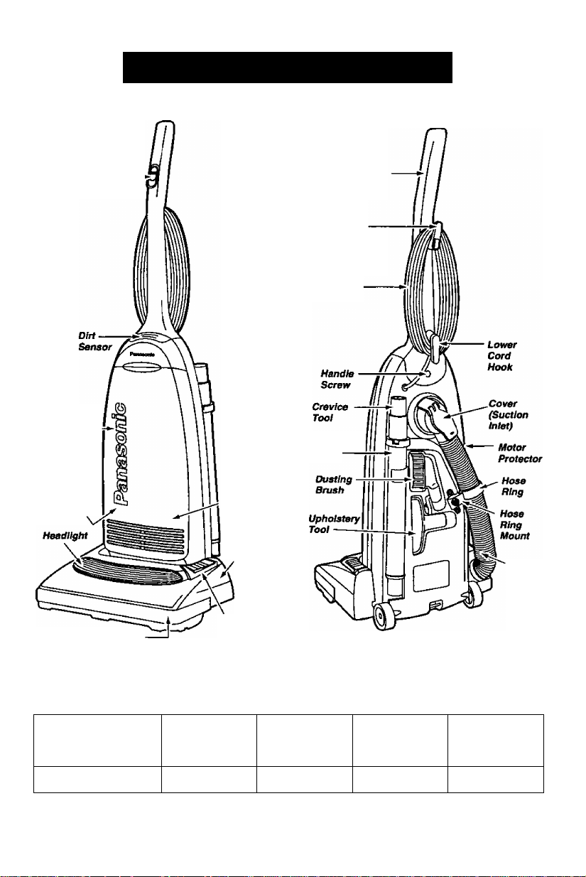
PARTS IDENTIFICATION
Dust Cover (Dust Bag
Inside)
Secondary
Filter (Inside
Dust
Compartment)
On/Dff
Switch
Exhaust
Filter (Inside
Dust Cover)
Nozzle
Quick
Release
Cord Hook
Power
Cord
Teleacr^lng
Wand
Handle
Hose
Foot Rest For
Furniture Guard
Handle Release
FEATURE CHART
(PANASONIC UPRIGHT VACUUM CLEANER)
^^^FEATURES
Model
MC-V6970
POWER DIRT
120 V. AC(60Hz)
12.0 Amps
SENSOR
Yes Yes 30
- 5 -
HEADLIGHT CORD
LENGTH
(feet)
Page 6
TO ASSEMBLE CLEANER
A WARNING
Do not plug into electrical supply until assembly is complete. Failure to do so could
result in electrical shock or Injury.
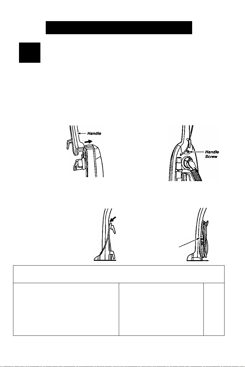
ATimCHING HANDLE 10 VACUDM GLEANER
Electiical Shock Hazard.
I-' ■ ¡8- "
The vacuum cleaner main body and handle are packed separately.
1. The handle
screw has been
installed for
shipping
purposes.
Please
remove the
screw before
inserting
handle. Insert
the handle as
shown in the
illustration. Make sure the On/Off switch
is in the Off position before installing.
3. There is a recessed area between
the upper cord storage hook base
and the handie that is designed to
secure the cord during vacuuming.
Always push the power cord down
into this recessed area to help keep
the cord from hanging near the
nozzle and being damaged.
2.
Insert the screw
that you removed.
Be sure the screw
is tightened, but
not overtightened.
4. Loosely wrap the cord around
both cord hooks. Secure the
plug head to the cord by
pushing the cord into the
retainers on the plug head.
Ratainer
(Plug Haad)
■ìMÉk
1. The upper cord hook has a 1J *
quick-release action. To
release the cord, rotate the
hook downward and the
complete power cord will /|l K
drop off the hook for M H |||
immediate use. ^
..:GS!NG.THE,DPRDHQQK,à
2. Do not unplug the power cord by
pulling on the cord. Grasp the
plug head and pull to unplug ij
the vacuum cleaner. V
Return the hook to the upright
position before attempting to
rewind the cord. U
____________
-6-
___
_____________
Z
Page 7
/^CHMENT (Tpls-oniliSard)fifl^SEMBi^
A
Do not get the power cord caught under the nozzle when using the vacuum or
attachments as It can be damaged by the agitator as It levolves.
CAUTION
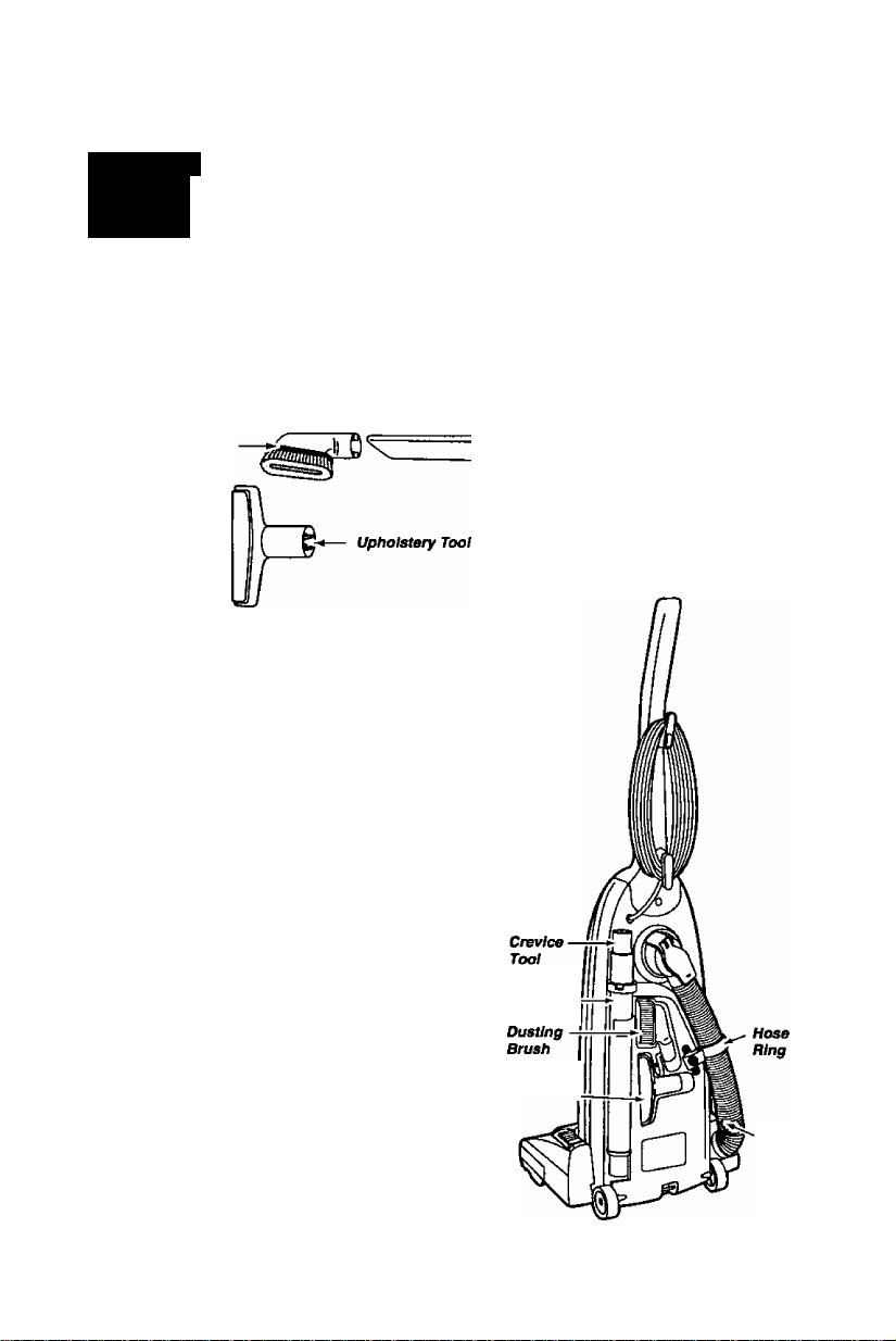
ATTACHMENTS
a
Dusting
Brush
The attachments should be conveniently positioned
in the back of the cleaner for easy access. Assemble
the hose and attachments to the cleaner as follows:
Insert the crevice tool, cleaning end down, into the
end of the telescoping wand nearest the locking ring.
A slight twist of the crevice tool will lock it into place.
Place the telescoping wand on the back of the cleaner
with the locking ring and crevice tool up, and the bottom
resting on the ledge near the wheel.
— Tetescoping
-----
' Wand
CrsWcs
Tool
The hose ring should be inserted into the slot to hold in
place only when vacuuming areas below the upper
cord hook.
Talescoping
Wand -
Upholstery
Tool
-7-
---------
' Hose
Page 8
SPECIAL FEATURES OF CLEANER
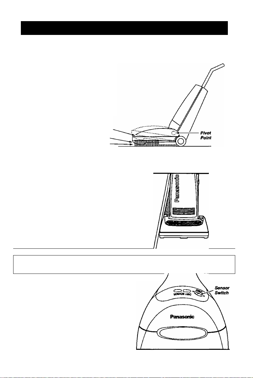
AVJTOMAfiC SELrADJUSTING NdZZLE
Your Panasonic upright vacuum cleaner is
designed with an automatic seif adjusting
nozzle. No manual adjustments are
required. The height of the nozzle is
instantly and automatically adjusted to any
carpet pile height. This self adjusting
feature allows the nozzle to float evenly
over ail carpet pile surfaces.
Nozzle
Deep Pile Cerpet
Shallow Pile Carpet
EDGE CLEANING FEATURE
The edge cleaning feature provides for
improved cleaning of carpets near waits and
furniture.
■#|feGlRiIpENS#ifc-'-
The electronic sensor is a feature which will
detect particles as they pass through the
vacuum cleaner.
Red light indicates dirt is being picked up by
the cieaner. Green iight indicates most of the
dirt has been picked up by the cleaner.
The dirt sensor indicators and sensor
sensitivity switch are located on the
topt of the switch cover. See the
Dirt Sensor section under To Operate
Cleaner section for operation.
-8-
Page 9

HOSE RING AND HOSE RING MOUNT«
The hose ring is a feature designed
to prevent tipping of the vacuum while
performing certain tasks that involve
the use of attachments. To use this
anti'tip feature, place the hose ring in the
hose ring mount as shown in tiie illustration.
Rotate this ring on the hose so that the
hose ring knob wiii align with the slot in the
hose ring mount and slide the ring down
firmly until it stops. For recommendations
on w^en to use the hose ring and the exact
location of tho hose ring mount see the Use of
Attachments section.
Hose
Ring Mount
TO OPERATE CLEANER
A
Do not use outlets above counters. Damage to items in №e surrounding areas
could occur. Be sure the smtch is in the off position while plugging títe cord in.
NOTE: To reduce the risk of electrical shock, this vacuum has a polarized plug, (one blade is wider
than the other). This plug will fit in a polarized outiet only one way. If the plug does not fit fully in the
outlet, reverse the plug. If it stiil does not fit, contact a qualified electrician to install the proper outleL
DO NOT CHANGE THE PLUG IN ANY WAY.
CAUTION
power cord
Page 10

OPERATION - As you vacuum, the red
indicator light will come on and stay on as
long as the sensor detects a high
concentration of particles passing through
the cleaner.
The green light indicates that most of the
cleaning is complete.
The sensor switch allows you to select the
sensitivity of the dirt sensor. The switch can
be set to Hi or Lo sensitivity.
Set the sensor switch to the Hi position when;
• Cleaning bare floors.
« Cleaning carpet with low pile height.
Set the sensor switch to the Lo position when;
• Cleaning heavily soiled areas.
• Cleaning carpet with deep pile.
• Cleaning new carpets.
Even with the sensor switch in the Lo position, the dirt sensor will detect carpet fuzz, especially
on new carpet, which may cause the red light to remain on longer than expected.
Sensor
SenshMty
Swftc/}
HANDLE ADJUSTMENTS
The handle may be lowered
to any position required. Just
step on the area, as indicated
by the illustration, and
lower the handle as
desired.
2. Middle position
This position is for
normal cleaning.
1. Upright position
The handle locks in this
position for storage.
The handle should
always be in an
upright position when
the cleaning tools
are used.
3. Low position
This position
is used for
cleaning
under
furniture.
- 10-
Page 11

A
DO NOT place hands or feef underneath the unit when using the attachment
toots. The agitator assembly begins to revolve rapidly when using attachments.
r ; USE OF ATTACHMENTS
. >\.
WARNING
Personal Injury Hazard when Using Attachments.
A
When using the attachments, the agitator begins rotating. Do not allow the
cleaner to remain in just one place for a period of time, as the agitator may damage
the floor surface. Avoid placing the cleaner on furniture, the fringed area of rugs,
deep pile carpeting, or carpeted stairs.' The Ideal position for the cleaner when
using sttachments Is for the unit to be on a level area with the handie in the full
uoriaht position.
To remove the hose from the nozzle, grasp the lower end of the hose at the nozzle
and twist as you pull out from the nozzle. Once the hose has been removed it can
be used as Is, or the telescoping wand can be used for further reach. Remove
the telescoping wand from the storage position on the vacuum cleaner. Remove
the crevice tod from the telescoping wand by pulling out while twisting slightly.
To extend the wand, turn the Ioch
on the locking ring and pull it out to rull length and lock the locking ring by turning
it to the LOCK position. The crevice tool, dusting brush, or upholstery tool can be
attached to the hose or the end of the wand. When connecting the attachments
to the hose or wand, always twist as you push down. If additional reach
Is required, the dusting brush or upholstery tool can be attached to
the crevice tool by simply sliding them over the narrow end. The
attached hose end swivels at the back of the vacuum cleaner to
make cleaning easier In all directions.
When using the attachments DO NOT overextend your reach
with the hose as it could tip the cleaner over. To'help prevent
tipping of the vacuum when using the attachments to ciean
areas below the upper cord hook the hose ring should be
placed in the hose ring mount. Above this level unhook
the hose ring from the mount.
Store attachments in their proper positions as shown in the
illustration and place the place the hose back into the nozzle.
CAUTION
OKing ring to the UNLOCK position as indicated
while twis
position
...............
TetescQp/ngjjj
Wood
Dusting
Brush
Upholstery
Tool
ATTACHMENT USE
CLEANING AREA
ATTACHMENT Furniture*
Between
Cushions* Drapes* Stairs Walls
Hose
CREVICE TOOl‘^==> X X
DUSTING BRUSH &
UPHOLSTERY a
TOOL
‘Always clean attachments before using on fabrics. Attachments used in dirty areas (such as under a
refrigerator) should not be used on other surfaces until ttwy are washed. They could leave marks.
(See the Cleaning Exterior and Attachments section.)
X X X X
X X X X
-11 -
X X X
Page 12

ROUTINE CARE OF CLEANER
Perfomning the fottowing tasks will keep vour new Panasonic vacuum cleaner operating at peak
performance levels and will insure these hi^ levels tor years to come. Check the Betore Requesting
Service section in this manual tor recommendations on performing some of these tasks to hefp
solve various problems that may occur.
A
Alway disconnect electrical supply before performing any service and/or cleaning
of the vacuum cleaner. Failure to do so could result in electrical shock or personal
injury from cleaner suddenly starting. Do not operate the cleaner without the
secondary foam filter. Be sure the secondary foam filter is properly installed.
Failure to do so could result in motor failure.
WARNING
«
Electric Shock or Personal Injury Hazard.
CLEANING SECONDARY FOAM FILTER
A secondary foam filter protects the motor
from dirt. When installing a new dust bag,
check the filter. Accumulated dirt in the
dust compartment wilt collect on this filter
and may restrict motor performance.
When the filter becomes dirty, puli it
from the bottom of the dust
compartment and clean by rinsing
it in water. When dry slide the filter
back into place. Insert the secondary
foam filter with a ruler or something flat
It should be fully inserted under the
plastic rib projections all the way to the
rear compartment wall.
ClI iIV# Si I '^*IIm»I Clrini
The exhaust filter is located Inside the dust cover. The
purpose of this filter is to remove dust and dirt from the
recirculated air. When installing a new dust bag,
check the filter. When the filter becomes dirty, Retainer
pull the filter and frame from the bottom of the
dust cover by pulling straight up on the two retainers
on the frame. Do one side at a time. Replace the filter.
DO NOT CLEAN WITH WATER. Place the new filter
In the frame with the four slots in the filter aligning
with the four tabs on the frame. Place the frame
and filter back into the dust cover making sure the
rough side is facing up. Snap the frame the back
into place by pressing down on the retainers.
This filter cannot be cleaned and should be replaced at least once each year if the cleaner
Is used at least one hour each week.
- 12 -
Exhaust Filter
^/octrostat/c^
and Frame
Retainer
Oust Cover
Page 13

CHA^JiiNG THEiDUST BAG
.............................
Always operate the vacuum with a genuine Panasonic Type U3 (Standard) or U6
(Electrostatic) dust bag installed. Panasonic dust bags may be ordered through
any authorized Panasonic dealer.
.'
...................
■
1. Pull outward on the
dust cover grip,
located on the top
front of the dust
cover and remove
the cover.
3. Spread out the end of the
new dust bag.
NOTE: Pull carefully so
as not to tear the bag at
the folds.
5. Reinsert the tabs
provided on the end
of the dust cover into
the grooves on the
dust compartment
to allow the cover
to rotate closed.
NOTE: The dust
cover must be
completely
and correctly
installed for
proper
operation
2. To remove the dust
bag, grasp the
cardboard portion
of the dust bag
and pull it out.
Attach the new dust
bag onto the bag
holder by holding
the cardboard
portion and
pushing back as
Illustrated.
Rotate the dust cover up
into the closed position
and press into place.
NOTE: The dust bag
should not be caught
between the
lower edge
of the dust
cover and
the gasket as
indicated by
the arrow in
the Illustration.
-13-
Page 14

A
When the lower plate la removed for any reason, before reinstalling, be sure
that all electrical wires are routed in a manner that prevents them from coming into
contact mth the lower plate, lower plate screws, or any moving parts. Be sure
the wires are not pinched in any way when the lower plate is reinstalled.
WARNING
Electrical Shock or Personal Injury Hazard.
REMOVlNG/INSTALyNG THE LOWER PLATE
Before replacing any parts, disconnect the vacuum
cleaner from the electrical outlet.
Replacing some of the parts in this section involves
the removal and installation of the lower plate. Lower
Always place paper under nozzle anytime the lower Plate
plate is removed to protect the floor surface.
To Remove Lower Plate.
Start by placing the handle in the low position. (See
the Handle Adjustments section.) Turn the vacuum
cleaner over, exposing the underside. Release the
lower plate by removing the three (3) screws that secure
the tower plate. Then remove the tower plate. Brush or
remove any residue that may exist in the belt area.
To Reinstall Lower Plate
Hook the front end of lower plate into the slots on the front end of the nozzle housing. Then
press the lower plate into place and fasten it by replacing the three (3) lower plate screws.
NOTE: To insure maximum cleaning efficiency, the belt should be checked regularly to make
sure it is in good condition. Check to see if the belt is stretched, cracked, or if
excessive slippage has occurred. Replace it if necessary.
Three
Screws.
'REPiACING'THEliEADLIGHTIBULB
1. Remove the lower plate using the procedure
in the Remowng/lnstalling the Lower Plate
section.
2. Grasp the bulb socket, wiggle the socket back
and forth while pulling it up out of the nozzle
housing. To remove the old bulb, push it in
toward the bulb socket while turning
counterclockwise, then remove.
3. Install the new bulb by pushing it in toward
the bulb socket and turning it clockwise. Use
any standard bayonet base appliance bulb
rated at 15 Watts.
Caution: Do not use a bulb rated over
15W. During extended use, heat from the
bulb could overheat surrounding plastic parts.
4. Reinsert the bulb socket into the nozzle housing by pushing it back down into the slot.
Replace the lower plate as outlined in the Removin^lnstailing the Lower Plate section.
Page 15

REPLACING THE DRIVE BELT
A
Be careful when removing agitator brush assembly. The belt tension is high. Failure
to do so could result in personal injury from agitator brush assembly releasing
quickiy and snapping away.
Unplug and turn the unit over. Remove the lower plate as described in the Removing/lnstalling the
Lower Plate section.
After checking the end caps, reinstall the agitator brush assembly back into the housing grooves.
After installing the agitator brush assembly, turn it by hand making sure that the belt is not twisted
and all rotating parts turn freely. Replace the lower plate as described in the Removing/lnstalling
the Lower Plate section.
WARNING
Personal Injury Hazard.
Remove the agitator brush assembly, (carefully lift it out),
and remove the worn or broken belt from the agitator
pulley and motor drive shaft.
CAUTION: The two end caps may come off along with
the two washers as you lift tne agitator assembly out.
Do not lose the two small washers.
Loop the new belt around the motor drive shaft and loop
it around the agitator pulley. See illustration for correct
belt routing. Use only a Panasonic Type UB drive belt.
Before reinserting the agitator brush assembly make sure
that the end capanvashers are on correctly. (See the
illustration in the Replacing the Agitator Assembly section.)
End Cap
Reinstall Agitator
Switch off the vacuum cleaner and unplug the power
cord before cleaning the agitator assembly. In order
to keep the cleaning efficiency high, clean the agitator
assembly regularly. Remove the lower plate if necessary.
See the Removing/lnstalling the Lower Plate section
tor the proper procedure.
Agitator assembly * Cut off any carpet pile and
lint entangled around the agitator assembly with
a pair of scissors as illustrated.
- 15-
Page 16

1. When to replace the agitator assembly.
The agitator assembly should be replaced when the brushes
are worn. Brushes should be checked by holding a card
across the lower plate (see illustration). If the bnstles on
the agitator assembly do not touch the card you should
replace the agitator assembly for best cleaning results.
2. How to replace the agitator assembly.
Place the vacuum cleaner handle in the low position. (See
the Handle Adjustments section.) Remove the lower plate
as outlined In the Removing/lnstalling the Lower Plate section. After the lower plate is
removed, carefully lift up the agitator assembly until it clears both sides of the nozzle
housing. While holding the agitator assembly up, remove the belt.
CAUTION: The two end caps may come off along with the two washers as you lift the
agitator assembly out. Do not lose the two small washers. Look at the exploded view of
the agitator assembly below for correct assembly of the parts.
3. To replace the agitator assembly.
Place the belt over the belt pulley on the agitator unit. (NOTE: There is a place for the belt
to fit on one end of the agitator assembly only.) Replace both washers and end caps (see
illustration below for correct assembly). After assembling the belt, washers and end caps,
place the agitator assembly back into the nozzle housing by aligning each end cap.
After completing the assembly, rotate the brush, turning it by hand to assure that
It rotates smoothly and the part is assembled correctly.
Replace the lower plate as outlined in the Removing/lnstalling the Lower Plate section.
- 16-
Page 17

CLEANING DIRT SENSOR OPTICS
The dirt sensor optics consists of two optic celis located
inside the bag holder. Occasionally, it may become
necessary to clean the two optic cells to assure
maximum performance. It is recommended
the optic cells be cleaned:
• When the red light does not light.
• When dirt or dust adheres to the optic cells.
• Whenever the dust bag is changed.
To clean the sensor, wipe the optic cells with a soft, dry
cloth. Never use cleaners or liquids as they can help
speed the recoating of the optic cells and make it
necessary to clean them much sooner than normal.
The dirts sensor area can be reached by removing
the dust cover and the dust bag.
ggg
..CLEANING EXTERIOR AND êTTêPWMENTSiï
1. Unplug cord from wall outlet. DO NOT drip water on cleaner.
2. Clean exterior using a clean, soft cloth that has been dipped in a solution of mild liquid
detergent and water, then wrung dry. Wipe dry after cleaning.
3. To reduce static electricity and dust build-up, wipe outer surface of cleaner and attachments.
4. Wash attachments in warm soapy water, rinse and air dry. Do not clean In dishwasher
or clothes washer.
DO NOT USE ATTACHMENTS IF THEY ARE WET
A
Attachments used in dirty areas (such as under a refrigerator) shouid not be used
on other surfiaces untii they are washed. They could leave marks.
CAUTION
-17-
Page 18

The hose located on the back of the vacuum cleaner carries the drt from the nozzle
up to the dust bag. If the hose should becorr« clogged:
1. Pull down on the suction inlet cover
and check for clogging in this area.
2. Disconnect the hose from the nozzle
and chedt the hose for clogging.
Plug in the vacuum deaner and turn it on.
While rurrdng the vacuum cleaner virith
the hose disconnected, stretch the hose
in and out to remove the dog.
Cover
(Suction
Inlet)
If the dog stni exists, turn the vacuum deaner
"OFP and unplug the power cord. Turn the
vacuum deaner over, exposing the inderside.
Remove the lower plate. Remove the short
nozzle pipe from Ihe nozzle by Sfling it
straight up. Inspect the hose end and nozzle
pipe arxf dear them of any obstojctions.
Reinstall the nozzle pipe, lower plate and
nozzle hose. See the Removing/lnstailing the
Lower Plata section for detailed instructions.
-18-
Page 19

BEFORE REQUESTING SERVICE
A
Disconnect the electrical supply before servicing or cleaning the unit Failure to do
so could result in electrical shock or personal injury from cleaner suddenly starting.
WARNING
Electrical Shock or Personal Injury Hazard.
Review this chart to find do-it-yourseif soiutions for minor performance
problems. Any service needed, other than those described in these
Operating Instructions, should be performed by an authorized service
representative.
PROBLEM POSSIBLE CAUSE POSSiBLE SOLUTION
Cleaner
will not run.
Poor job of dirt
pickup.
1. Unplugged at wall outlet.
2. On/Off switch not turned on.
3. Tripped circuit breaker/blown
fuse at household service panel.
1. Full or clogged dust bag.
2. Broken belt.
3. Clogged nozzle. 3. Clean nozzle area.
4. Hose not inserted fully. 4. Insert hose.
5. Worn agitator assembly. 5. Replace agitator assembly.
1. Plug in firmly. Push On/Otf switch
to On.
2. Push On/Off switch to On.
3. Reset circLilt breaker or replace
fuse.
1. Change bag.
2. Replace belt.
Light will
not work.
Dust escapes
the paper bag.
Dirt Sensor will
not work.
6. Hole in hose. 6. Replace hose.
7. Dust cover improperly installed.
1. Burned out light bulb.
1. Bag improperly installed.
2. Bag tom.
1. Dirty optic cells. 1. Clean optic cells.
-19-
7. Properly install dust cover.
1. Replace light bulb.
1. Properly install bag.
2. Replace bag.
Page 20

NOTES
-20-
Page 21

NOTES
-21 -
Page 22

NOTES
-22-
Page 23

WARRANTY
Panasonic Vacuum Cleaner
Limited Warranty
SALES COMPANY (collectively referred to as the warrantor) will repar this
product with new or refurbished parts free of charge, in the
Rico one (1) year from ttie date of
materials or workmanship, ^eluded are the following items which require
normal replacement: Disposable Dust Bag, Filters, Betts, Light Bulb, Agitator
Brushes and Battery (if supplied).
Carry-in service in the continental U.S.A. can be obtained during tiie warrar%
period from a Matsushita Services Company (MSC) Factory Servicenter. To
locate an authorized MSC Servicenter call 1-800-545-2672 toll free. Service in
Puerto Rico can be obtained during the warranty period by calling the telephone
numbers listed in the Servicenter Directorv. This
the original purchaser. A purchase receipt or other proof of date of original
purchase will be required before warranty performance is rendered.
This warranty only covers failures due to defects in materials or workmanship
which occur ciuring normal use and does not cover damage wNch occurs in
shipment or failures which are caused by products not supplied by the
warrantor, or failures which result from accident, misuse, abuse, neglect,
mishandling, misapplication, alteration modification of the product, or
commercial use such as hotel, office, restaurant or rent use of the product, or
service by anyone other than an authorized Servicenter, or damage that is
attributable to acts of God.
MATSUSHITA CONSUMER ELECTRONICS COMPANY OR PANASONIC
ico one (1) year from tiie date of original purchase in the event of a defect in
r1q‘ ■. ■ ■ ■
irectory. This warranty is extended only to
U.S.A.
or Puerto
LIMITS AND EXCLUSIONS: There are no express warranties except as listed
above.
The warrantor SHALL NOT BE LIABLE FOR INCIDENTAL OR
CONSEQUENTIAL DAMAGES RESULTING FROM THE USE OF THIS
PRODUCT, OR ARISING OUT OF ANY BREACH OF THIS WARRANTY. ALL
EXPRESS AND IMPLIED WARRANTIES, INCLUDING THE WARRANTIES OF
MERCHANTABILITY AND FITNESS FOR A PARTICULAR PURPOSE, ARE
LIMITED TO THE APPLICABLE WARRANTY PERIOD SET FORTH ABOVE.
Some states do not allow the exclusion or limitation of incidental or
consequential damages or limitations oh how tong an implied warranty lasts, so
the above exclusions or limitations may not apply to you.
This warranty gives you specific legal rights and you may also have other
rights which vary from state to state.
If a problem with this product develops during or after tine warranty period, you
may contact your dealer or Servicenter. If the problem is not handled to your
satisfaction, then write to the Customer Satisfaction Center at the listed address
on the back cover.
-23-
Page 24

WHAT TO DO WHEN SERVICE IS NEEDED
If your Panasonic Vacuum Cleaner needs service, look in the yellow pages of the
telephone book under "Home Appliance Service" for your nearest Matsushita
Service Company ("MSC") Factory Servicenter, or MSC authorized Servicenter,
or call 1-800-545-2672, toll free to find a convenient servicenter. Do NOT send
the product to the Executive or Regional Sales offices. They are NOT equipped
to make repairs.
If you ship the product
CaiBfully pack and send It prepaid, adequately insured arKl preferably in the original carton. Mtach a postage-
paid letter to the outside of the carton, which contains a description of your complainL DO NOT send the
pmduct to the Exeetitive or Regkmai Sales Offices. They are NOT equipped to mate repairs.
Customer's Record
Model No.
Serial No..
Dealer's Address.
Date of Purchase,
Consurrters requinng product inforniation
jir operating assistance with a consumer,;
ii^product stray Id c0ntact:^5
■f ■ ■ Y" ■-W " ■
CUSTOMER SATISFACTION
'W: 'WbÉìfSfÈRfP'" ' ""V'
, DEPARTMENT 2F-3 -
" so Meadowlarids Parkway s
Secaucus, N.J. 07094
<201)348-9090^ ¿Z:
MATSUSHITA CONSUMER ELECTRONICS
COMPANY, DIVISION OF MATSUSHITA ELECTRIC
CORPORATION OF AMERICA
One Panasonic Way
Secaucus, New Jersey 07094
C01ZAHV00U00
Dealer's Name
DIAL TOLL FREE
^ 1^0-543-2672
''^MàtdMiiHitai'$ërvtëes (
5 24 hours a day*
7 days ia week
y
PANASONIC SALES COMPANY, DIVISION OF
MATSUSHITA ELECTRIC OF PUERTO RICO INC.
AVE. 65 de Infanterìa, Km 9.5
San Gabriel Industrial Park
Tel. (809) 750-4300 Fax. (809) 768-2910
Carolina, Puerto Rico 00985
T ■
■
■»Y ■
M
M
'n
(-PSC-)
Printed in U.S.A.
 Loading...