

Page 1
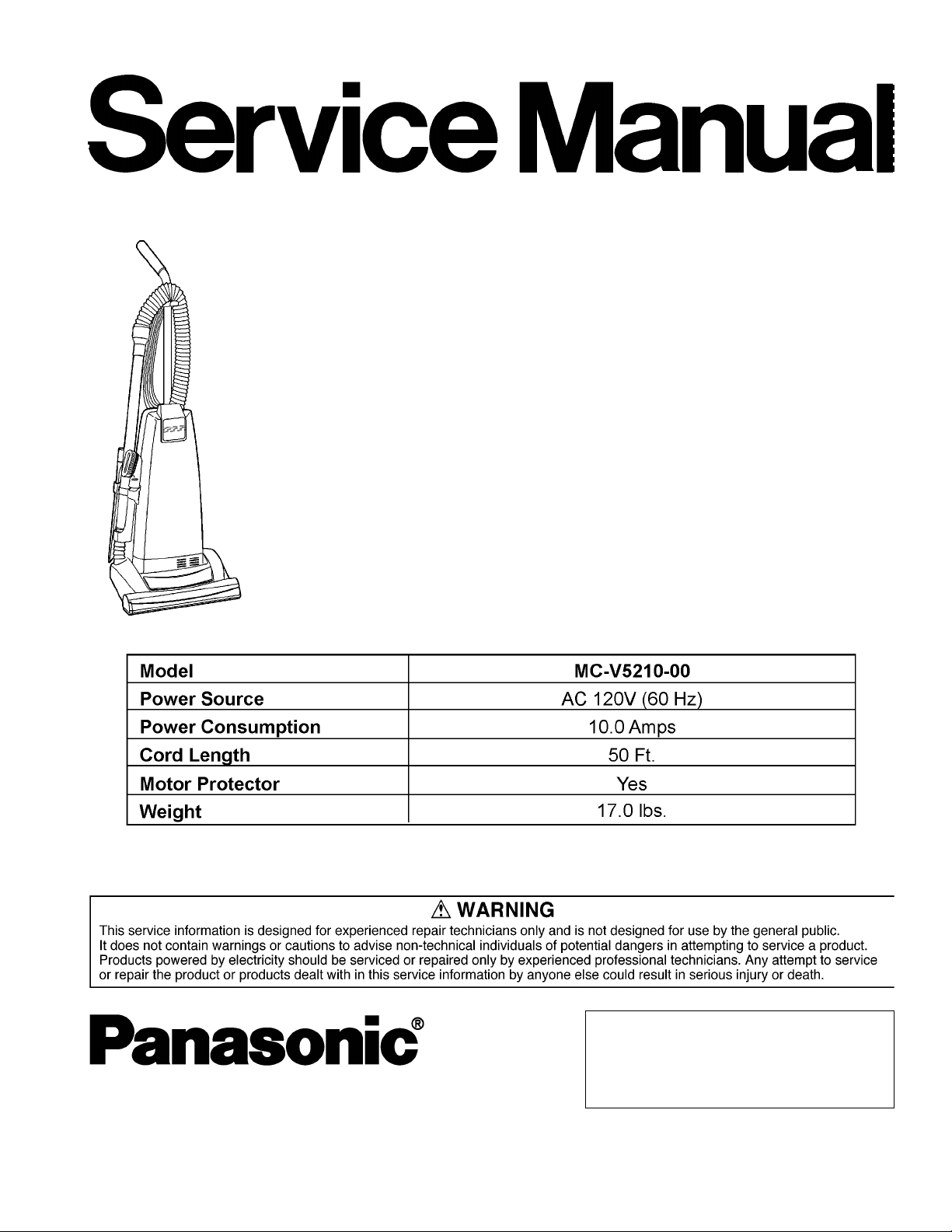
Vacuum Cleaner
MC-V5210-00
Order Number MAC0507002C1
Specifications are subject to change without notice for further improvement.
© 2005 PANASONIC HOME APPLIANCES
COMPANY OF NORTH AMERICA, DIVISION
OF P ANASONIC CORPORATION OF NORTH
AMERICA. All rights reserved. Unauthorized
copying and distribution is a violation of law.
Page 2
1 WIRING DIAGRAM AND DRAWING
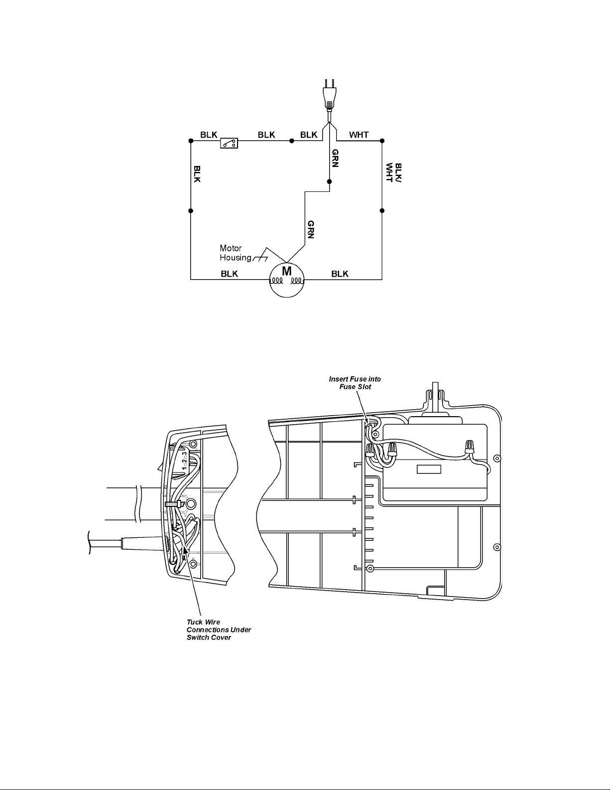
1.1. Wiring Diagram
1.2. PICTORIAL DIAGRAM
NOTE:
For general servicing, it is necessary to eliminate pinching of any wire during reassembly. After servicing any electrical component or electrical enclosure, the unit should be reassembled and checked for dielectric breakdown or current leakage.
2
Page 3
2 EXPLODED VIEW AND PARTS LIST
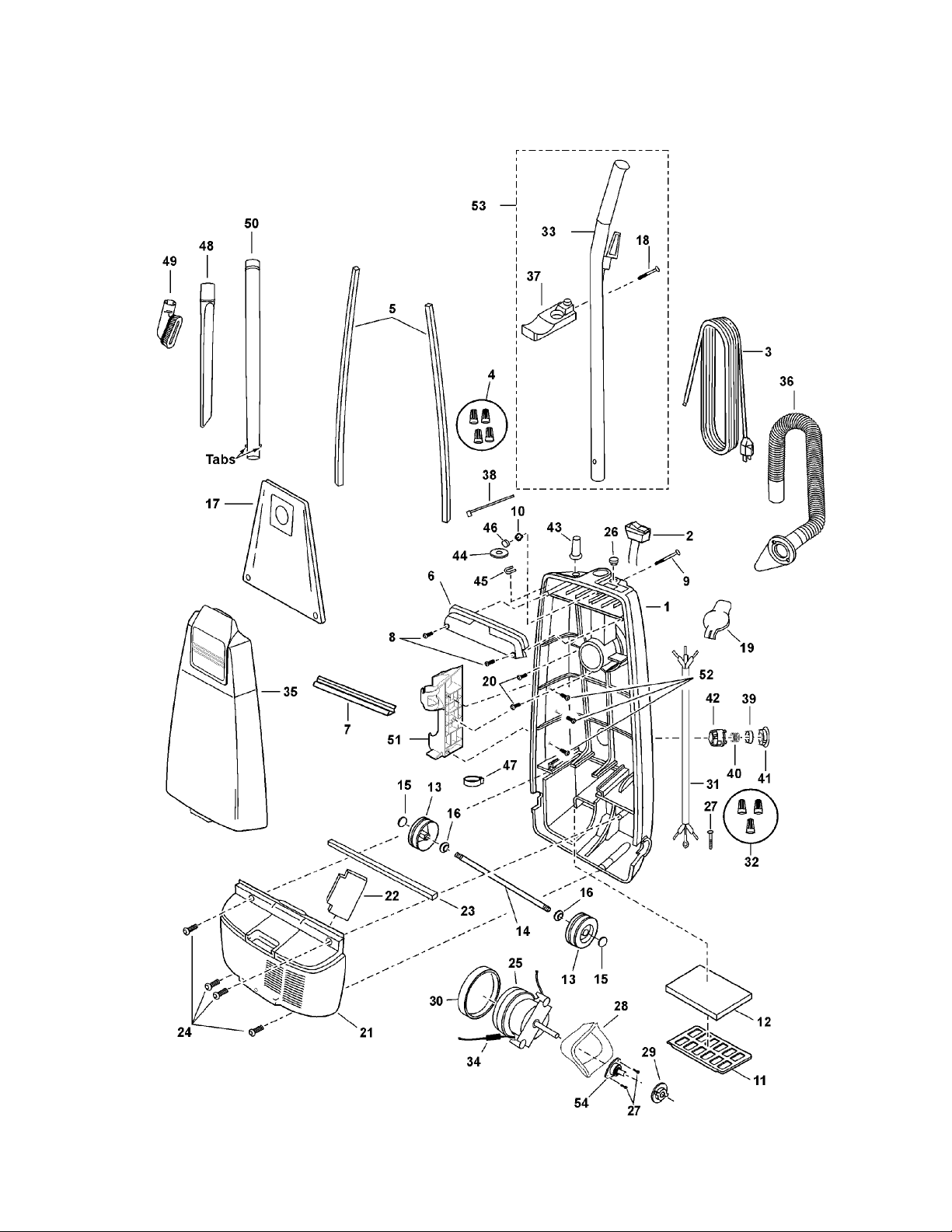
2.1. Body
2.1.1. Exploded View
3
Page 4

2.1.2. Parts List (Body)
Ref. No. Part No. Part Name & Description Quantity Remarks
1 AC88KCUDZV07 Dust Container Machined 1 Includes items 38, 45 and 46
2 AMC98E-V000U Switch ON/OFF 1 Includes item 38 and 46
3 AC94EAPNZY02 Power Cord 1 Includes items 38, 44 and 46
4 AMC-1CTCE23 Wire Nut 4 Shipped 10 per package
5 AC66KV01V06 Packing Dust Container 2
6 AC03EV06V06 Switch Cover 1 Includes item 38 and 46
7 AC73KV0ZV06 Packing Switch Cover 1
8 AXTN4+16BFY Switch Cover Screw 2 Shipped 10 per package
9 AMC73B-V00 Screw Handle 1
10 AMP21B-170 Nut Handle Screw 1
11 AMC32K-V00 Supporter Filter 1
12 AC37KAAEZ00 HEPA Filter Secondary 1
13 AMC01C-V00U Wheel 2
14 AC16CUSZ00 Roller Shaft 1
15 AC74SUSZ00 Wheel Stopper 2 Shipped 10 per package
16 AXWG6E115FY Washer 2 Shipped 10 per package
17 AC16KBYTZ000 Dust Bag 1
18 AXTN4+45BFY Screw Hose Holder 1 Shipped 10 per package
19 AC02HYUZV06 Cover Inlet 1
20 AXTN4+16BFY Screw Inlet 2
21 AC99FCUDZV07 Motor Case 1
22 AMC02L-V00 Packing Rear Cover 1
23 AC19FJPZV06 Packing Motor Case 1
24 AXTN4+20BFY Screw Motor Case 4 Shipped 10 per package
25 AC92FAPNZ00 Fan Motor 1
26 AC38HAPNZU00 Cover Cap 1
27 AXYN4+E10FFY Screw Ground 3 Shipped 10 per package
28 AC99GAMMZ00 Noise Suppressor 1
29 AC03FAFYZ00 Motor Support Rear 1
30 AMC02F-E00 Motor Support Front 1
31 AC37GTEZ0U Wirecord 1
32 AMC-1CTCE23 Wire Nut 3
33 AC64BATNZ00 Handle 1
34 AC99WARGZ00 Motor Lead Assembly 1
35 AC60KCMYZU03 Dust Cover 1
36 AC84PJPZV06 Stretch Hose 1
37 AC23PJPZV07 Hose Holder 1
38 AMC596-702 Tie Cable 1
39 AC69KJMZV06 Motor Protector 1
40 AC70KJMZ00 Protector Spring Silver 1
41 AC18MJMZV06 Protector Support 1
42 AC68KJMZV06 Protector Case 1
43 AC51E4GZU01 Rubber Protector 1
44 AXWE10J223FE Flat Washer 1 Shipped 10 per package
45 AC06WAPNZ00 Cord Retainer 1
46 AC61LAGMZ00 Packing 1
47 AC53RJPZV07 Hose Hook 1
48 AC60RZFZVU6 Crevice Tool 1
49 AC88RYUZV06 Dusting Brush 1
50 AC40PJP1V06 Wand Extension 1
51 AC70PJPZV07 Wand Holder 1
52 AXTN4+16BFY Screw Tool Holder 3 Shipped 10 per package
53 AC95BATNZV07 Handle Assembly 1 Includes items 18, 33, 37
54 AC25SAFYZ00 Motor Flange 1
4
Page 5

2.2. Nozzle Housing
2.2.1. Exploded View
5
Page 6

2.2.2. Parts List (Nozzle Housing)
Ref. No Part No. Part Name & Description Quantity Remarks
1 AC01ACUDZUU3 Nozzle Housing 1
2 AC10ACRSZV07 Furniture Guard 1
3 AC21HCRSZU03 Window 1
4 AMC25S-V00 Plastic Shaft 1
5 AC34PAJDZV06 Nozzle Hose 1
6 AC43AAFY200 Brac ket Assembly 1
7 AXTN4+16BFY Screw 4 Shipped 10 per package
8 AC47A2VZV07 Pedal 1
9 AC58AAFVZ00 Spring (Pedal) 1
10 AMC51A-2V0 Shaft (Pedal) 1
11 AC11S2VZW00 Belt Cover Assembly 1
12 AC62FAVGZ00 Belt Cover Washer 2 Shipped 10 per package
13 AC28SJPZ00 Belt 1
14 AC02ACRSZW0H Body (Upper) 1
15 AC12ACRSZW0H Cap (Body) 1
16 AMC68A-V30 Screws 2 Shipped 10 per package
17 AC90QNGZV06 Wheel 2
18 AC16CNXZ00 Shaft (Wheel) 2
19 AC91ACRSZ000 Lower Plate As sem bly 1 Includes items 29, 30 and 31
20 AMC68N-V30K Latch (Lower Plate) 2
21 AC70NYUZ00 Spring (St op Latch) 2
22 AC74ACRSZ000 Packing (Lower Plate) 1
23 AC74ACRSZ000 Packing (Lower Plate) 1
24 AMC39A-2V0 Packing (Lower Plate) 3
25 AC92SBVNZ000 Agitator Assembly 1
26 AXTN4+10BFY Screw 1 Shipped 10 per package
27 AC82ACRRZV07 Agitator Holder 1
28 AC85RBFT0000 Brush Set 1
29 AC29SBVNZ000 Agitator Pulley 1
30 AC41SBVNZ000 Agitator Holder 1
31 AC44KBVNZ000 Washer 2
32 AC96DBVNZ000 End Cap (Right) 1
33 AC97DBVNZ000 End Cap (Left) 1
34 AC57RBVNZ000 Agitator Shaft 1
35 AC56RBYYZ000 Brush Holder 1
36 AC23FBVNZ000 E-Clip 1 Shipped 10 per package
37 AC74SBVNZ000 Spacer 1
38 AC34SBYYZ000 Spacer (Brushes) 3
6
Page 7

2.3. Packing Material
2.3.1. Exploded View
2.3.2. Parts List
Ref. No. Part No. Part Name & Description Quantity Remarks
1 AC61ZCCAZ000 Packaging Assembly 1 Includes 1 and items a-g
2 AC01ZCUDZ000 Operating Instructions 1
7
Page 8

3 REPLACEMENT INSTRUCTIONS
3.1. Lower Plate Replacement
3.1.1. Removal
1. Before servicing any parts, disconnect vacuum from electrical outlet.
2. Place paper under nozzle whenever lower plate is
removed to protect floor.
3. Place handle in upright position and turn vacuum over to
expose lower plate.
3.2. Belt Replacement
3.2.1. Removal
1. Remove lower plate.
2. Lift rear belt cover and remove agitator holder.
3. Remove agitator by carefully lifting out.
4. Remove worn or broken belt.
4. Release lower plate by pressing two (2) latches inward.
5. Remove lower plate and remove any residue that may
exist in belt area.
3.1.2. Installation
1. Close the rear belt cover.
2. Hook the front of the lower plate into the slots on the front
of the nozzle housing. Press the lower plate down into
place.
3. Fasten the lower plate by pushing the two (2) latches outward.
NOTE: For general servicing, it is necessary to eliminate
pinching of any wire during reassembly. After servicing
any electrical component or electrical enclosure, the unit
should be reassembled and checked for dielectric breakdown or current leakage.
5. Clean agitator.
3.2.2. Installation
1. Loop new belt (Panasonic Type UB8 only) around motor
shaft and agitator pulley; see illustration for correct belt
routing.
2. Reinstall agitator back into nozzle housing grooves.
3. Close rear belt cover and reinstall agitator holder.
4. After reinstalling the agitator, turn it by hand to make sure
that belt is not twisted or pinched and that all rotating
parts turn freely.
5. Reinstall lower plate.
8
Page 9

3.3. Agitator Assembly
Replacement
3.3.1. Removal
1. The brushes are replaceable separately. When the
brushes need replacing, the agitator assembly will have
to be removed.
2. Remove the lower plate as outlined in the LOWER
PLATE REPLACEMENT section.
3. Remove the agitator assembly as outlined in the BELT
REPLACEMENT section.
.
3.3.2. Installation
1. Place the belt around the motor shaft.
2. Start the new agitator assembly back into the nozzle
housing by placing the side opposite the belt partially into
the slot. T h e sm al l tabs should be al i gn e d wi th t he nozz le
and the other against the lower plate. This will hold the
agitator in place and leave both hands free to place
enough tension on the belt to allow that side of the agitator to return to the nozzle housing slot.
3. Place the belt around the agitator pulley on the agitator
assembly.
4. Use both hands to pull the belt tight, slide the agitator
assembly firmly into the slots on each end of the nozzle
housing.
5. Rotate the agitator assembly by hand to insure nothing
rubs and to check for correct assembly.
6. Replace the lower plate a s outl ined in the LO WER PLATE
REMOV AL/INSTALLATION section.
3.4. Brush Replacement
1. The agitator brushes should be replaced when the
brushes are worn. Brushes should be checked by holding
a card across the low er pla te. If the bristl es on t he agit ato r
assembly do not touch the card you should replace all the
brushes for best cleaning results.
3.4.1. Removal
1. Remove the lower plate as outlined in the LOWER
PLATE REPLACEMENT section.
2. Remove the agitator assembly as outlined in the BELT
REPLACMENT section.
3. The agitator assembly may now be disassembled and the
brushes replaced.
4. Carefully remove the E-clip from the agitator shaft, do not
misplace. Remove the right brush support. Pull the agitator shaft out of the opposite end of the.
5. Pull or pry out the agitator pulley and agitator holder.
6. Push each brush out of the agitator.
9
Page 10

7. Install new brushes by reversing procedure.
8. Reinstall agitator holder and agitator pulley completely.
9. Reinstall the agitator shaft, end cap and E-clip.
10. Position belt over agitator pulley on the agitator.
11. Reinstall agitator and lower plate.
3.5. Nozzle Housing Replacement
6. Lift up on the nozzle housing, plastic shaft side first.
7. The nozzle housing can now be easily rotated from the
motor shaft.
NOTE: If the motor case cover is removed, DO NOT turn
vacuum over as the motor may fall out.
3.5.2. Installation
1. Fit the nozzle from the motor shaft side first, and rotate it
into place on the dust container as illustrated.
3.5.1. Removal
1. Remove the lower plate as outlined in the LOWER
PLATE REMOVAL/INSTALLATION section.
2. Remove agitator assembly as outlined in the respective
sections.
3. Remove upper body by removing four (4) screws.
2. Slide the plastic shaft thro ugh the noz zle ho using and into
the dust c ontain er. Make sure t hat t he sl ot on t he bot tom
of the plastic shaft is down and fitted onto the projection.
3. Re-install the motor case. Be carefull not to over tighten
the four (4) motor case screws.
4. Carefully turn vacuum cleaner over.
5. Install belt, agitator assembly, and the lower plate according to the respective in structions.
NOTE: For general servicin g, it is nec es sa ry to eli mi nat e pinching of any wire during reassembly. After servicing any electrical
component or electrical enclosure, the unit should be reassembled and checked for dielectric breakdown or current leakage.
4. Remove nozzle hose from upper body.
5. Carefully turn vacuum over. Remove motor case by
removing four (4) screws.
10
Page 11

3.6. Power Cord / On-Off Switch
3.7. Thermal Overload
Replacement
3.6.1. Removal
1. Remove the d ust cover and switch cove r to expose the
electrical connections of the power cord, on-off switch
and wire cord.
2. Remove the flat washer and cord retainer. Remove the
wire connections, and wire tie, if present .
3. Remove the on-off switch (for on-off switch replacement)
by depressing the ret aining tabs while pus hi ng u p an d out
of the dust cpntainer at the same time.
4. Pull the power cord out of the dust container (for power
cord replacement).
3.6.2. Installation
1. Insert the new power cord (power cord replacement only)
into the dust container as far as necessary in order to
secure the power cord. The proper location is approximately one and one eighth inches/thirty millimeters (1 1/
8”/30 mm) of new power cord outer jacket extending past
the cord retainer. Attach wires with wire connectors
according to the wiring diagram in the front of this manual.
2. For switch replacement only, insert the new ON/OFF
switch facing toward you, into the dust container until
secured by the retaining tabs. Use a wire tie in the location illustrated taking care not to overtighten it. Tuck the
wire connectors back into the dust container as illustrated
in the close-up view.
Replacement
3.7.1. Removal
1. Remove motor, as shown in motor replacement section.
2. Remove wire nut from th e lead wire that c ont ains the the rmal protector. Remove old thermal protector and replace
with new thermal pro tec tor. Reconnec t w i re n ut to t herm al
overload. Replace lead wire containing protector wires
back into the groove.
3.7.2. Installation
1. Place the motor back into the dust co nta iner, following the
instructions given in the motor replacement section.
3.8. Motor Replacement
3.8.1. Removal
1. Remove the dust cover by grasping the top near the onoff switch and pulling sharply out toward you.
3. Ensure that the ins ulator packing is installe d correctly.
4. Replace the switch cover, the two (2) switch cover
screws, and the dust cover. Care should be taken not to
pinch wires and make sure that the switch cover goes on
easily and stays flat. If there is resistance to the switch
cover lyi ng flat and i n place, st op, remove the cover a nd
make sure that no wires are b eing pi nched . DO NOT U SE
A POWER SCREWDRIVER TO SECURE THE COVER.
NOTE: For general servicin g, it is nec es sa ry to eliminate pinching of any wire during reassembly. After servicing any electrical
component or electrical enclosure, the unit should be reassem-
bled and checked for dielectric breakdown or current leakage.
2. Remove the lower plate, agitator assembly, belt, the plastic shaft, and the nozzle housing as instructed in the
respective removal sections.
3. Turn the vacuum over to the front side.
4. Remove the four (4) scr ews fr om the moto r ca se and t hen
remove the motor case.
5. Disconnect the motor leads and remove the motor.
Remove the motor support rubber (rear), noise suppressor, flange and the motor support rubber (front). Place
these items on the new motor.
11
Page 12

3.8.2. Installation
1. Place the motor back into the dust compartment with
motor flange positioned as illustrated.
2. Rewire per the Pictorial Diagram.
3. Replace the motor case and the four (4) screws.
4. Turn the vacuum back over and replace the plastic shaft,
nozzle housing, belt, agitator assembly, and lower plate
according to the respective installation instructions.
12
 Loading...