

Page 1
ServiceManual
MC-V5203
ORDER NO. MAC060503U
E4
SPECIFICATIONS
2003 PANASONIC CONSUMER ELECTRONICS COMPANY,
DIVISION OF MATSUSHITA ELECTRIC CORPORATION OF AMERICA
All rights reserved. Unauthorized copying and distribution is a violation of law.
PANASONIC CONSUMER ELECTRONICS
COMPANY, DIVISION OF MATSUSHITA
ELECTRIC CORPORATION OF AMERICA
One Panasonic Way
Secaucus, New Jersey 07094
World Wide Web Address
http://www.panasonic.com
Printed in U.S.A.
PANASONIC SALES COMPANY, DIVISION
OF MATSUSHITA ELECTRIC OF
PUERTO RICO INC. (“PSC”)
Ave. 65 de Infanteria, Km. 9.5
San Gabriel Industrial Park
Carolina, Puerto Rico 00985
Tel. (809) 750-4300 Fax (809) 768-2910
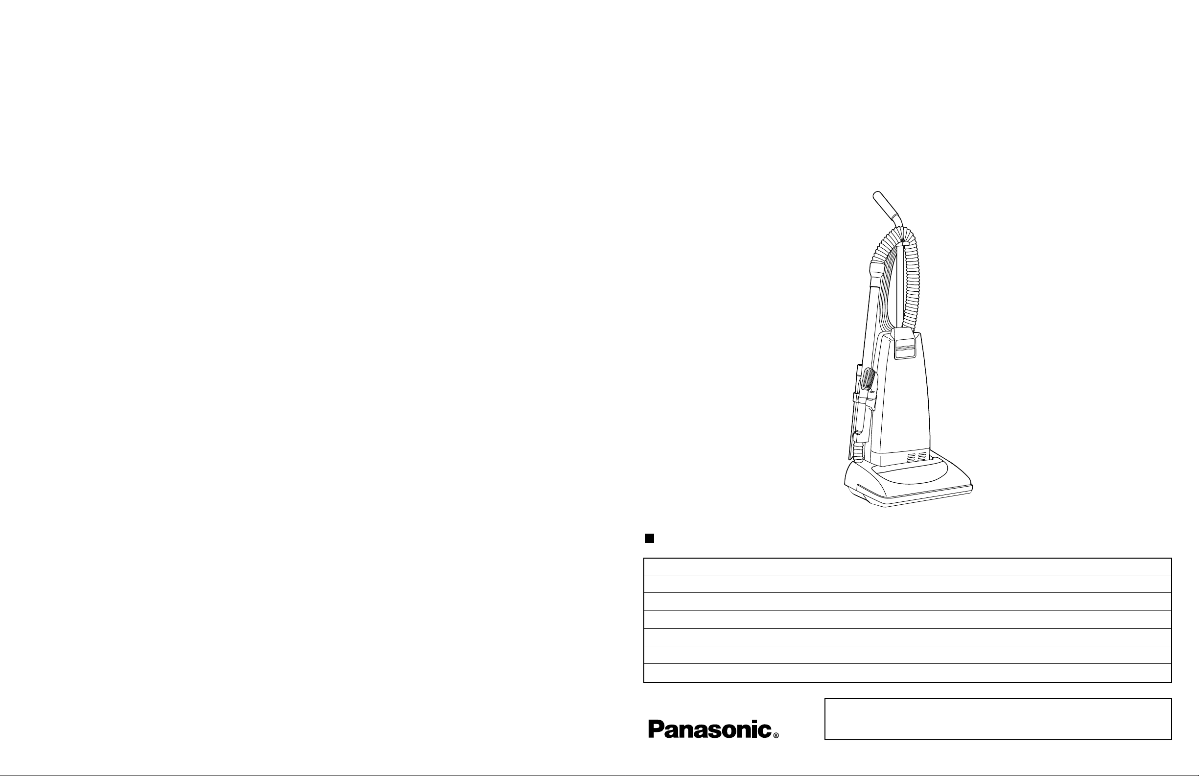
Commercial Vacuum Cleaner
Model MC-V5203
Power Source AC 120V (60 Hz
)
Power Consumption 10.0 Amps
Cord Length 50Ft.
Motor Protector Yes
Height Adjust Automatic
Weight 17 lbs.
Page 2

- 19 -- 2 -
TABLE OF CONTENTS
SPECIFICATIONS ........................................................................................................................... Front Cover
SCHEMATIC DIAGRAM .................................................................................................................................. 3
WIRE MANAGEMENT DRAWING................................................................................................................... 3
EXPLODED VIEW (NOZZLE HOUSING) ....................................................................................................... 4
PARTS LIST (NOZZLE HOUSING)................................................................................................................. 5
EXPLODED VIEW (AGITATOR ASSEMBLY).................................................................................................. 4
PARTS LIST (AGITATOR ASSEMBLY) ........................................................................................................... 5
EXPLODED VIEW (MOTOR HOUSING, MOTOR, HANDLE, AND BODY) .................................................... 6
PARTS LIST (MOTOR HOUSING, MOTOR, HANDLE, AND BODY).............................................................. 7
EXPLODED VIEW (MOTOR FAN ASSEMBLY)................................................................................................8
PARTS LIST (MOTOR FAN ASSEMBLY)..........................................................................................................8
EXPLODED VIEW (PACKING MATERIALS)................................................................................................... 9
PARTS LIST (PACKING MATERIALS)............................................................................................................ 9
LOWER PLATE REMOVAL/INSTALLATION ................................................................................................. 10
AGITATOR ASSEMBLY REMOVAL/INSTALLATION..................................................................................... 11
BELT REPLACEMENT................................................................................................................................... 11
BRUSH REPLACEMENT .............................................................................................................................. 12
NOZZLE HOUSING AND NOZZLE HOSE REPLACEMENT........................................................................ 13
SWITCH COVER AREA WIRING MANAGEMENT....................................................................................... 14
POWER CORD/ON-OFF SWITCH REPLACEMENT................................................................................ 14-15
HOSE REPLACEMENT ................................................................................................................................ 15
MOTOR REPLACEMENT ............................................................................................................................. 16
CARBON BRUSH REPLACEMENT.............................................................................................................. 16
MOTOR FAN REPLACEMENT........................................................................................................................17
NOTES .......................................................................................................................................................18-19
This service information is designed for experienced repair technicians only and is not
designed for use by the general public. It does not contain warnings or cautions to advise
non-technical individuals of potential dangers in attempting to service a product. Products
powered by electricity should be serviced or repaired only by experienced professional
technicians. Any attempt to service or repair the product or products dealt with in this
service information by anyone else could result in serious injury or death.
WARNING
NOTES
Page 3
- 3 -- 18 -
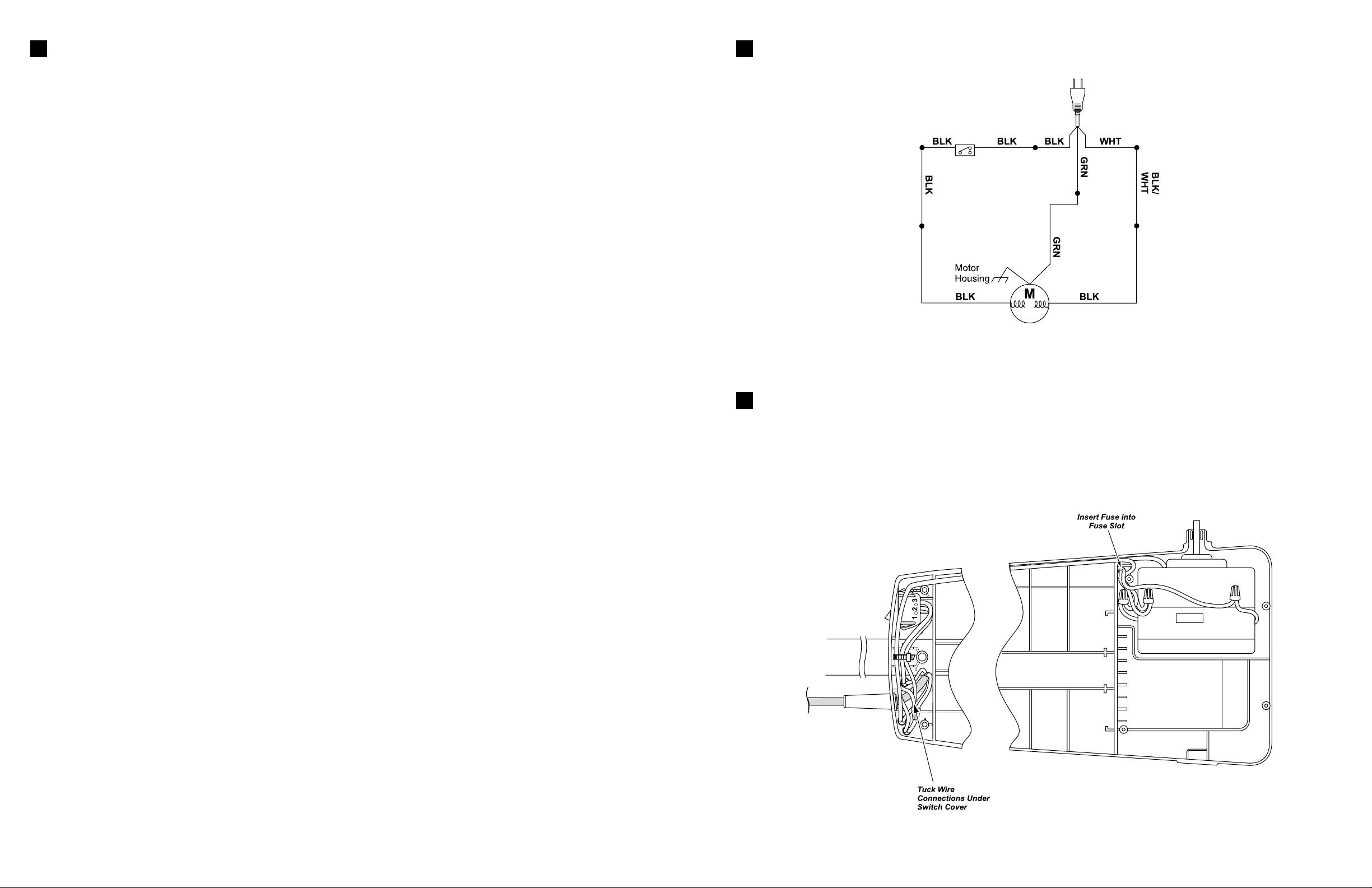
SCHEMATIC DIAGRAM
NOTE: For general servicing, it is necessary to eliminate pinching of any wire during reassembly. After servicing
any electrical component or electrical enclosure, the unit should be reassembled and checked for dielectric
breakdown or current leakage.
WIRING MANAGEMENT DRA WING
NOTE: Do not pinch any wires during reassembly. After servicing any electrical
component or electrical enclosure, the unit should be reassembled and checked for
dielectric breakdown or current leakage.
NOTES
Page 4

- 4 - - 17 -
EXPLODED VIEW
(NOZZLE HOUSING)… BLOCK
A
A-10
EXPLODED VIEW (AGITATOR ASSEMBLY)... BLOCK
B
MOTOR FAN REPLACEMENT
Removal
1. Mark the position of the fan case's location on the motor with a pencil, or score it with a
sharp object before disassembly. This will aid you in reassembling the fan case, (Fig. 21).
2. The fan case has three (3) crimped sections on it to hold the case onto the motor. These
will have to be straightened by using a pair of needle nose pliers and by tapping out on the
crimp area with a flat blade screwdriver. Be sure and straighten all three (3) crimped areas,
(Fig. 21). Remove the fan case from the motor unit.
3. Tools required to remove the fan from the shaft will be a 1/8 - inch Allen wrench, a 1/2 -inch
offset box wrench, torque wrench, and a hammer.
NOTE: Be careful when handling the sheet metal parts as there could be sharp edges. Do
not scratch or bend the motor shaft. Scratches will cause belt breakage during operation.
4. Place the 1/2 - inch box wrench over the 1/2 -inch hex nut that holds the fan onto the
motor shaft, (Fig. 22). While holding the wrench on the nut, place the 1/8 -inch Allen wrench into
the end of the motor shaft and loosen the nut while holding the Allen wrench still. The nut will
have to be turned clockwise as it is a left-hand thread. After removing the nut, remove the fan,
(Fig. 22). There is a spacer left on the motor that is not required to be removed. If spacer is
removed, reassemble per exploded view, (Fig. 22).
* Some models will have this washer and spacer.
Installation
1. Place the new fan onto the motor shaft, making sure that the spacer is still
on the motor. The large diameter hole, approximately 1 1/8 inch, will be on
the top of the fan as you install it.
2. Install the flat washer with the burr side of the washer
facing away from the fan, (Fig. 23). Screw the nut onto the motor shaft,
turning it counterclockwise, left-hand threads, and torque to 20-30-inch
pounds. Be sure to hold the motor shaft by placing the 1/8-inch allen
wrench into the motor shaft end while torquing the
nut, (Fig. 22).
3. Align your marks on the fan case as you put the fan case back on and
tap around the case uniformly. Tap the three (3) crimped areas over and
then use a flat blade screwdriver to recrimp them.
4. See (Fig. 24) for reassembly specifications.
EXPLODED VIEW
(Fig. 24)
(Fig. 21)
(Fig. 23)
(Fig. 22)
A-17
A-27
A-16
A-19
A-3
A-7
A-8
A-12
A-9
A-13
A-14
A-6
A-4
A-5
A-2
A-16
A-15
A-6
A-28
A-22
A-29
A-27
A-1
A-24
A-20
A-21
A-18
A-22
A-24
A-21
A-28
A-25
A-26
A-23
A-11
Tap Down on the
3 Crimped Areas
Mark Case
As Shown
Washer
*
Spacer
Ref
No.
1
8/ " Allen
Wrench
*
Part
Name
1. Fan Case
2. Nut
3. Washer -
Crimped
Area (3)
½" Offset
Box Wrench
½" Nut
Flat
Washer
Fan
Spacer
Burr Side
B-36
B-34
B-33
B-31
B-39
B-32
B-41
B-35
A-30
B-34
Use these specifications
to assure that the fan
case has been tapped
back to the original position.
B-38
B-37
B-40
4.2"/4.5"
(106/114 mm)
These measurements
are approximate.
5a.
5b.
4. Fan
Smooth Side
*
*
5. Spacer
NOTE: Space 5
*
is used on some models.
5a washer and
5b space used on
other models.
6. Brush Assembly
7. Bracket
8. Screw A
Page 5

- 16 - - 5 -
PARTS LIST (NOZZLE HOUSING)… BLOCK
A
Ref. No. Part Name & Description Part No. Quantity Remarks
A - 1 Nozzle Housing ACØ1ACCAZUU3 1
A - 2 Window AC21HAFVZUØ3 1
A - 3 Plastic Shaft AMC25S-VØØ 1
A - 4 Furniture Guard AC1ØAAGZVØ7 1
A - 5 Light Cover AC24HAFVZUØ3 1
A - 6 Screw, Light Cover AXTN4+2ØBFY 2
A - 7 Frame AMC43A-2VØ 1
A - 8 Pedal Spring AC58AAFVZØØ 1
A - 9 Pedal Shaft AMC51A-V3Ø 1
A - 10 Screw, Pedal Assembly AXTN4+1ØBFY 2
A - 11 Screw, Pedal Assembly AXTN4+16BFY 1
A - 12 Pedal, Handle Release AMC47A-2VØU 1
A - 13 Belt AC28SJPZØØ 1
A - 14 Lower Plate Assembly AC91AATEZVØ7 1 (Includes A-15, A-16, A-17, A-22, A-23,
A-24, A-26, A-27, A-28, A-29)
A - 15 Lower Plate AC27AATEZVØ7 1
A - 16 Lower Plate Packing AC19AARKZVØØ 1
A - 17 Belt Cover AC43SAFVZØØ 1
A - 18 Screw, Slider Support AC68AZAZØØ 1
A - 19 Nozzle Hose AC34PAJDZVØ6 1
A - 20 Slider Support AC53KAFVZØØ 1
A - 21 Screw, Slider Support AXTN4+16BFY 2
A - 22 Latch, Lower Plate AMC68N-AVØK 2
A - 23 Stop Latch Spring AC7ØNYUZØØ 2
A - 24 Screw, Latch AMC68A-V3Ø 2
A - 25 Body, Lower Plate ACØ6AAJUZØØ 1
A - 26 Wheel AC9ØQNGZVØ6 2
A - 27 Roller Shaft AC16CNXZØØ 2
A - 28 Screw, Lower Plate AXTN4+16BFY 2
A - 29 Agitator Assembly AC92SATEZØØ 1 (Includes B-31 thru B-41)
PARTS LIST (AGITATOR ASSEMBLY)... BLOCK
B
Ref. No. Part Name & Description Part No. Quantity Remarks
B-31 Brush, Strips (Set of 4) AC85RBFTØØØØ 1
B-32 Pulley, Agitator AC29SARGZØØ 1
B-33 Holder, Agitator AC41SJM1ØØ 1
B-34 Filter, Agitator AC44KJMZØØ 2
B-35 Cap, Left End AC97DJMZØØ 1
B-36 Cap, Right End AC96DJMZØØ 1
B-37 Shaft, Agitator AC57RATEZØØ 1
B-38 E-Clip AMC-XUC4FY 1
B-39 Holder, Brush AC84RJMZØØ 1
B-40 Pin, Spring AMC-XPL16A8WFR 1
B-41 Spacer AC74SATEZØØ 1
Removal
1. Remove the dust cover by grasping the top near the ON/OFF switch and pulling
sharply out toward you.
2. Remove the lower plate, agitator assembly, belt, the plastic shaft, and the nozzle
housing as instructed in the respective removal sections.
3. Turn the vacuum over to the front side and remove the four (4) screws from the motor case
and then remove the motor case, (Fig. 17).
4. Disconnect the motor leads and ground wire and remove the motor.
5. Remove the plastic motor cover by carefully prying out the tabs which secure it to the
motor, (Fig. 18). Snap the motor cover onto the new motor.
6. Remove the motor support rubber (rear), noise suppressor, and the motor support rubber
(front). Place these items on the new motor. See the C Block for a view of these.
Installation
1. Connect all wires according to the SCHEMATIC DIAGRAM.
2. Place the motor into the dust compartment with brushes aligned to the front edge of the
dust compartment. The motor support (rear) must also align with the tabs in the same direction.
3. Route all wires according to the WIRE MANAGEMENT DRAWING.
4. Replace the motor case and the four (4) screws.
5. Turn the vacuum back over and replace the plastic shaft, nozzle housing, belt,
agitator assembly, and lower plate according to the respective installation instructions.
MOTOR REPLACEMENT
(Fig. 17)
(Fig. 18)
CARBON BRUSH REPLACEMENT
Removal and Installation
1. After removing the motor and plastic motor cover, see MOTOR
REPLACEMENT, make sure that you have properly identified it. Note
specifically that this motor is made in the U.S.A. as identified by the label on
the side of the motor, or Made in U.S.A. stamped on the bottom.
2. Remove the amp terminals located on each brush end, (Fig. 19).
Replace the brush assembly which should include the brush holder.
Reinstall the amp terminals onto the new brush assembly. Complete brush
change on one side before starting on the other side.
NOTE: Do not drop screws into the motor.
3. There are two (2) brushes located on the motor as identified in (Fig. 19).
A phillips head screwdriver will be required to remove the four (4) screws that
hold the brush holders onto the motor.
See (Fig. 19) for screw location.
NOTE: When inserting the brush assembly, be sure that the
TAB on the bottom of the brush holder is positioned in the trough as
shown in (Fig. 20).
4. Check and clean commutator.
5. Replace the brush holder bracket with two (2) Phillips screws on each
side of the motor.
6. As a final check to assure proper installation of brushes,
measure across the brushes for the approximate dimension as shown in
(Fig. 20).
7. Place the plastic motor cover back on the unit and re-install the motor back into the unit by following the installation instructions in
the MOTOR REPLACEMENT.
(Fig. 19)
(Fig. 20)
Amp
Terminal
Carbon Brushes
Made in U.S.A.
Label
Screws
Trough
Brush Holder
Tab Location
Motor Case
Green Ground Wire
(Some Models)
Brush
Screws
115-120 mm
4.5-4.7"
Brush to Brush
Dimension is Approximate
Page 6

- 6 - - 15 -
EXPLODED VIEW
(BODY, MOTOR HOUSING, AND MOTOR)… BLOCK
C
Removal
1. Remove the dust cover and dust bag.
2. Remove the end of the hose from the wand. Remove the hose by removing the two screws which secure it to the dust container.
Replacement
1. Install the new hose by replacing the two screws which secure it to the dust container.
2. Replace the hose onto the wand.
3. Replace the dust bag and dust cover.
HOSE REPLACEMENT
Installation
1. Insert the new power cord (power cord replacement only) into the dust compartment as far as necessary in order to place a new cord
retainer in proper location on power cord. The proper location is approximately one and one eighth inches/thirty millimeters (1 1/8”/30
mm) of new power cord yellow outer jacket extending past the cord retainer and washer. The washer goes between the cord retainer and
the dust compartment. Attach wires with wire connectors according to the wiring diagram in the front of this manual. ONLY USE A NEW
CORD RETAINER, DO NOT REUSE A CORD RETAINER.
2. For switch replacement only, insert the new ON/OFF switch with the numbers 1,2,3, facing toward you, into the dust compartment
until secured by the retaining tabs. Use a wire tie with the part number listed in the C Block parts list and place it in the location shown in
(Fig. 15) taking care not to overtighten it. Tuck the wire connectors back into the dust compartment as shown in the close-up view in (Fig. 15).
3. Ensure that the Insulator Packing is installed correctly, (see Fig. 16).
4. Replace the switch cover, the two (2) switch cover screws, and the dust cover. Care should be taken not to pinch wires and make sure
that the switch cover goes on easily and stays flat. If there is resistance to the switch cover lying flat and in place, stop, remove the cover
and make sure that no wires are being pinched. DO NOT USE A POWER SCREWDRIVER TO SECURE THE COVER.
NOTE: Any service involving the handle or switch cover area should be followed up with a dielectric or current leakage check
of the unit. If you do not have the equipment or are not familiar with the test procedures, take the unit to an authorized servicer.
POWER CORD/ON-OFF SWITCH REPLACEMENT (Cont.)
C-50
C-48
C-49
C-5
C-54
C-33
C-37
C-18
Tabs
C-17
C-35
C-7
C-15
C-8
C-51
C-13
C-16
C-44
C-6
C-4
C-38
C-46
C-45
C-20
C-10
C-47
C-43
C-26
C-1
C-2
C-9
C-52
C-42
C-31
C-27
C-39
C-40
C-19
C-41
C-3
C-36
C-24
C-21
C-22
C-23
C-16
C-13
C-30
C-15
C-32
C-53
C-34
C-25
C-28
C-29
C-12
C-11
C-14
Page 7

- 7 -- 14 -
PARTS LIST
(MOTOR HOUSING, MOTOR, HANDLE, AND BODY)... BLOCK
C
Ref. No. Part Name & Description Part No. Quantity Remarks
C-1 Dust Container, Machined AC88KAPNZV17 1 (Includes C-38, C-44, C-45, C-46, C-47, C-48)
C-2 Switch, ON/OFF AMC98E-VØØØU 1 (Includes C-38, C-46)
C-3 Power Cord AC94EAPNZYØ2 1 (Includes C-38, C-44, C-45, C-46)
C-4 Wire Nut AMC-1CTCE23 4
C-5 Packing Dust Container AC66KVØ1VØ6 2
C-6 Switch, Cover ACØ3EVØ7VØ6 1 (Includes C-46)
C-7 Packing Switch Cover AC73KVØZVØ6 1
C-8 Switch Cover Screw AXTN+16BFY 2
C-9 Screw, Handle AMC73B-VØØ 1
C-10 Nut, Handle Screw AMP21B-17Ø 1
C-11 Supporter, Filter AMC32K-VØØ 1
C-12 HEPA Filter, Secondary AC37KAAEZØØ 1
C-13 Wheel AMCØ1C-VØØU 2
C-14 Roller Shaft AC16CUSZØØ 1
C-15 Wheel Stopper AC74SUSZØØ 2
C-16 Washer AXWG6E115FY 2
C-17 Dust Bag AC16KBYTZØØØ 1
C-18 Screw, Hose Holder AXTN4+45BFY 1
C-19 Cover, Inlet ACØ2HYUZVØ6 1
C-20 Screw, Inlet AXTN4+16BFY 2
C-21 Motor Case AC99FAAEZVØ7 1
C-22 Packing, Rear Cover AMCØ2L-VØØ 1
C-23 Packing, Motor Case AC19FJPZVØ6 1
C-24 Screw, Motor Case AXTN4+2ØBFY 4
C-25 Fan Motor AC92FAPNZØØ 1
C-26 Cover Cap AC38HAPNZØU 1
C-27 Screw, Ground AXYN4+E1ØFFY 1
C-28 Noise Suppressor AC99GAMMZØØ 1
C-29 Motor Support, Rear AMCØ3F-VØØ 1
C-30 Motor Support, Front AMCØ2F-EØØ 1
C-31 Wirecord AC37GTEZØU 1
C-32 Wire Nut AMC-1CTCE23 3
C-33 Handle AC64BATNZØØ 1
C-34 Motor Lead Assembly AC99WARGZØØ 1
C-35 Dust Cover AC6ØKCCAZUU3 1
C-36 Stretch Hose AC84PJPZVØ6 1
C-37 Hose Holder AC23PJPZVØ7 1
C-38 Tie Cable AMC596-7ØØ 1
C-39 Motor Protector AC69KJMZVØ6 1
C-40 Protector Spring, Silver AC7ØKJMZØØ 1
C-41 Protector Support AC18MJMZVØ6 1
C-42 Protector Case AC68KJMZVØ6 1
C-43 Rubber Protector AC51E4GZUØ1 1
C-44 Flat Washer AXWE1ØJ223FE 1
C-45 Cord Retainer ACØ6WAPNZØØ 1
C-46 Packing AC61LAGMZØØ 1
C-47 Hose Hook AC53RJPZVØ7 1
C-48 Crevice Tool AC6ØRZFZVU6 1
C-49 Dusting Brush AC88RYUZVØ6 1
C-50 Wand, Extension AC4ØPJP1VØ6 1
C-51 Wand Holder AC7ØPJPZVØ7 1
C-52 Screw, Tool Holder AXTN4+16BFY 3
C-53 Cap, Motor AC93FTEZØU 1
C-54 Handle Assembly AC95BATNZVØ7 1 (Includes C-18, C-33, C-37)
Removal
1. Remove the dust cover and switch cover to expose the electrical connections of the power cord, ON/OFF switch, and wire cord.
2. Pull the power cord into the dust compartment in order to remove the strain relief (for power cord replacement) by prying or cutting,
remove the wire connectors, and wire tie, if present.
3. Remove the ON/OFF switch (for ON/OFF switch replacement) by depressing the switch retaining tabs while pushing up out of the
dust compartment at the same time.
4. Pull the power cord out of the dust compartment (for power cord replacement).
(Continued on p. 14)
POWER CORD/ON-OFF SWITCH REPLACEMENT
SWITCH COVER AREA WIRING MANAGEMENT
(Fig. 15)
(Fig. 16)
DUST COMPARTMENT COMPONENT LOCATIONS
To Plug End
Power Cord
(With Yellow
Outer Jacket)
Wire
Connectors
Cord
Retainer
Insulator
Packing
(Approx. 1 1/8 in./30 mm
Beyond the Strain Relief)
123
Wire
Tie
On/Off
Switch
Wire
Cord
(3 Wire)
Page 8

- 13 -- 8 -
PARTS LIST
(MOTOR FAN ASSEMBLY)
EXPLODED VIEW
(MOTOR F AN ASSEMBLY)
Ref. No. Part Name & Description Part No. Quantity Remarks
1 Fan Case AMC53F-AVØØU 1
2 Nut AMC33F-ACØØU 1
3 Washer AMC62F-AVØØU 1
4 Fan AC98FRFZØØ 1
5 Washer AC62FRFZØØ 1
6 Spacer AC6ØFRFZØØ 1
7 Brush Assembly AC27FRFZØØ 1(Set)
8 Bracket ACØ2DV3ZØU 2
9 Screws AC4ØDV3ØØU 4
NOZZLE HOUSING AND SHORT HOSE REPLACEMENT
Removal
1. Remove the lower plate as outlined in the LOWER
PLATE REMOVAL/INSTALLATION section.
2. Remove the belt and agitator assembly as outlined in
the respective sections.
3. Remove the nozzle hose by pulling it up out of the
nozzle housing and then pulling it, while twisting, out of
the wand holder.
4. Insert a flat blade screwdriver between the nozzle
housing and the plastic shaft, pry out the plastic shaft as
illustrated, (Fig. 10).
5. Remove the nozzle housing as illustrated, (Fig 11).
6. Remove the handle release assembly as outlined in its removal
section.
7. Remove the light cover, (Fig. 12) by removing the two (2) screws from
the nozzle housing and pushing out on the cover (Fig. 12).
8. Remove window, furniture guard and slider support.
NOTE: If the motor case cover is removed, DO NOT turn vacuum
over as the motor may fall out.
Installation
1. Install the light cover, handle release assembly, furniture guard,
window and slider support in the new nozzle housing. (Fig. 12).
2. Fit the nozzle from the motor shaft side first and rotate it into
place on the dust container as illustrated, (Fig. 13).
3. Slide the plastic shaft through the nozzle housing and into
the dust container. Make sure that the slot on the bottom of
the plastic shaft is down and fitted onto the projection.
4. Reassemble the nozzle hose by inserting it into the wand holder
then place the other end into the nozzle housing with the tab fitting into the slot.
5. Install the belt, agitator assembly, and the lower plate according to the respective instructions.
(Fig.11)
(Fig. 12)
(Fig. 10)
(Fig. 13)
(Fig. 14)
1
2
3
4
5
6
7
8
9
Handle Release
Assembly
Furniture
Guard
Light
Cover
Light Cover Screws
Plastic
Shaft
Nozzle
Housing
Projection
Page 9

- 9 -- 12 -
EXPLODED VIEW
(PACKAGING)
PARTS LIST
(PACKAGING)
Ref. No. Part Name & Description Part No. Quantity Remarks
1 Packaging Assembly AC61ZCCAZØØØ 1 Includes 1 and items a-i
2 Operating Instructions ACØ1ZCCAZØØØ 1
When to replace brushes
1. The agitator brushes should be replaced when they are worn. Brushes should be checked by
holding a card across the lower plate, (Fig. 5). If the bristles on the agitator assembly do not
touch the card you should replace all the brushes for best cleaning results.
Removal
NOTE: Use extreme care when prying or depressing these items with a screwdriver in
order to help prevent personal injury or damage to the vacuum.
Be careful when working around the ends of the metal brush holder since sharp edges
may be present.
1. Remove the lower plate as outlined in the LOWER PLATE REMOVAL/
INSTALLATION section.
2. Remove the agitator assembly as outlined in the AGITATOR ASSEMBLY
REMOVAL/INSTALLATION section.
3. The agitator assembly may now be dissassembled and the brushes replaced.
4. Using a small screwdriver, carefully remove the E-clip from the agitator shaft,
(Fig. 6), DO NOT misplace. Remove the right end cap. Pull the agitator shaft out of the opposite
end of the agitator.
5. Pull or pry out the agitator pulley and agitator holder, (Fig. 7).
6. The brushes can now be replaced, (Fig. 8). Each brush must be inserted so that the end with
eleven (11) tufts is placed on the side of the brush holder closest to the belt pulley. Push each
brush as shown in the illustration until it is free from the agitator body. Install the new brushes by
reversing the procedure.
Installation
1. Pull the new brushes into the slots in the brush holder.
2. Reinstall the agitator holder and agitator pulley, making sure they are completely
and firmly inserted. See (Fig. 9) for an exploded view.
3. Reinstall the agitator shaft, brush support, and the small E-clip.
4. Reinstall the agitator assembly as outlined in the AGITATOR ASSEMBLY
REMOVAL/INSTALLATION section.
5. Reinstall the lower plate as outlined in the LOWER PLATE REMOVAL/
INSTALLATION section.
NOTE: When the brushes are properly installed they will not hit the lower plate
as the agitator assembly rotates.
BRUSH REPLACEMENT
(Fig. 5)
(Fig. 6)
(Fig. 7)
(Fig. 8)
AGITATOR ASSEMBLY
(Fig. 8)
(Fig. 9)
e
Unit Bag
(Handle)
a
Cushion “A”
Operating
Instructions
2
d
Unit Bag
(Power Cord)
b
Cushion “B”
Unit Bag
(Body)
1
Carton
Pedal
Protector
i
c
g
Unit Bag
(Attachment
Assembly)
Spacer
Filter
Agitator Shaft
Belt Pulley
Agitator
Body
End Caps
Brush
Filter
Agitator Holder
E- Clip
fPacking
Insert
Page 10

- 11 -- 10 -
Removal
1. Place the handle in the upright position.
2. Turn the vacuum cleaner over exposing the underside. Release the lower
plate by pressing inward the two (2) latches and depressing the two locking
tabs that secure the lower plate, (Fig. 1).
3. Remove the lower plate and remove any residue that may exist in the belt area.
Installation
1. Hook the front of the lower plate into the slots on the front of the nozzle housing. Press the lower plate down until the
locking tabs snap into place.
2. Press outward on the two (2) lower plate latches to fasten.
NOTE: For general servicing, it is necessary to eliminate pinching of any wire during reassembly. After servicing any
electrical component or electrical enclosure, the unit should be reassembled and checked for dielectric breakdown or current
leakage.
LOWER PLATE REMOVAL/INSTALLATION
(Fig. 1)
Removal
The brushes are replaceable separately. When the brushes need replacing, the
agitator assembly will have to be removed.
1. Remove the lower plate as outlined in the LOWER PLATE REMOVAL/
INSTALLATION section.
2. Carefully lift up on the agitator assembly until it clears both sides of the nozzle housing,
(Fig. 2).
3. Remove the belt from the motor shaft by sliding it off between the end of the shaft and the
nozzle housing.
Installation
1. Place the belt around the motor shaft, (Fig. 3).
2. Start the agitator assembly back into the nozzle housing by placing the side
opposite the belt partially into the slot. This will hold the agitator in place and leave
both hands free to place enough tension on the belt to allow that side of the agitator
to return to the nozzle housing slot.
3. Place the belt around the agitator pulley on the agitator assembly.
NOTE: There is a place for the belt to fit on one end of the agitator
assembly only. This is the agitator pulley.
4. Use both hands to pull the belt tight, (Fig. 4), and slide the agitator
assembly firmly into the slots on each end of the nozzle housing.
5 Rotate the agitator assembly by hand to insure nothing rubs and to check
for correct assembly.
6. Replace the lower plate as outlined in the LOWER PLATE
REMOVAL/INSTALLATION section.
AGITATOR ASSEMBLY REMOVAL/INSTALLATION
(Fig. 2)
(Fig. 3)
(Fig. 4)
BELT REPLACEMENT
Removal
1. Follow all of the removal instructions outlined in the AGITATOR ASSEMBLY REMOVAL/INSTALLATION section.
Installation
2. Place the new belt around the motor shaft and follow the installation instructions in the AGITATOR ASSEMBLY
REMOVAL/INSTALLATION section.
Motor Shaft
 Loading...