

Panasonic MADLN01SE, MADLN11SE, MADLN05SE, MADLN15SE, MBDLN21SE Reference Specifications
...Page 1
No.SX-DSV03015
REFERENCE SPECIFICATIONS
MODEL
Product Name: AC servo driver
Part Number : MINAS-A6 series (Basic type)
Issued on Sept. 1, 2015
Revised on Sept. 14, 2016
Motor Business Unit, Electromechanical Control Business Division
Automotive & Industrial Systems Company, Panasonic Corporation
7-1-1 Morofuku , D aito-City, Osaka 574-0044 Japan
Page 2

No. SX-DSV03015
REVISIONS
Date Page Rev. Description Signed
Spt. 1, 2015
Nov. 1, 2015
Sept.14,2016
P1, P3,P53, P65
P5
P56 ADDED THE HARMONIC SUPPRESSION MEASURES
- NEWLY ISSUED -
- 1.0 DEFAULT VALUE OF THE PARAMETERS CHANGED -
P1 2.0 UPDATE THE MODEL DESIGNATION CODE -
P1 CHANGED THE NAME OF COMPANY
ADDED THE MODEL OF MEDLN93SE
ADDED THE FUNCTIONS
P63~65
CORRECT THE INRUSH CURRENTS AT CONTROL POWER SUPPLY
Motor Business Unit, Panasonic Corporation
Page 3
No. SX-DSV03015
Contents
1. Scope ································································································································· 1
2. Model designation code ············································································································ 1
3. Product line-up ······················································································································ 2
4. General specifications ·············································································································· 4
4-1 General specification ········································································································· 4
4-2 Specifications by model ······································································································ 5
5. Appearance and part names ········································································································ 6
6. Configuration of connectors and terminal blocks ··············································································· 11
6-1 Power connector XA , XB , XC , XD and terminal block ························································ 11
6-2 USB connector X1 ··········································································································· 15
6-3 Parallel I/O connector, X4 ·································································································· 16
6-4 Encoder connector X6 ······································································································· 20
7. Dimensions ·························································································································· 23
8. Wiring ································································································································ 35
8-1 Used cables and maximum cable lengths ·················································································· 35
8-2 Various connectors ············································································································ 35
8-3 Precautions for wiring ········································································································ 36
9. Compliance with global standards ································································································ 49
9-1 Conforming standards ········································································································ 49
9-2 European EC directive········································································································ 49
9-3 Peripheral device configuration ····························································································· 50
9-4 List of peripheral devices applicable to servo driver ····································································· 53
9-5 Compliance with UL stand a r d ······························································································· 55
9-6 Radio waves act (South Korea) precautions ··············································································· 56
9-7 Compliance with SEMI F47 instantaneous stop standard ······························································· 56
9-8 Harmonic suppression measures ···························································································· 56
10. Safety precautions ················································································································· 57
11. Life and warranty ·················································································································· 61
11-1 Life expectancy of the driver ······························································································· 61
11-2 Typical life ··················································································································· 61
11-3 Warranty period ·············································································································· 61
12. Others ······························································································································· 62
13. Specification for each model ····································································································· 63
The maximum value of torque limit setup
Default value of the parameters
Motor Business Unit, Panasonic Corporation
Page 4

Custom specification (Alphanumeric)
Size
1. Scope
These specifications relate to the servo driver for the AC servo system that is comprised of the AC servo motor
manufactured and supplied by Motor Business Unit, Electromechanical Control Business Division, Automotive &
Industrial amplifier Systems Company, Pan ason ic C orporat ion .
2. Model designation code
Notation of the machine designation code is as follows:
A : Size A
B : Size B
C : Size C
D : Size D
E : Size E
F : Size F
AC Servo drive
L : A6 series
Safety function
N : Without functional safety
Maximum instantaneous
output current
0 : 6 A
1 : 8 A
2 : 12 A
3 : 22 A
4 : 24 A
5 : 40 A
8 : 60 A
9 : 80 A
A : 100 A
B : 120 A
1 2 3 4 5 6 7 8 9 10 11 12
M A D L N 1 5 S E * * *
User Interface
• Rotary type
Power supply voltage
No. SX-DSV03015 - 1 -
E : Basic type
1 : Single phase 100 V
3 : 3 phase 200 V
5 : Single or 3 phase 200 V
Motor Business Unit, Panasonic Corporation
Page 5
No. SX-DSV03015 - 2 -
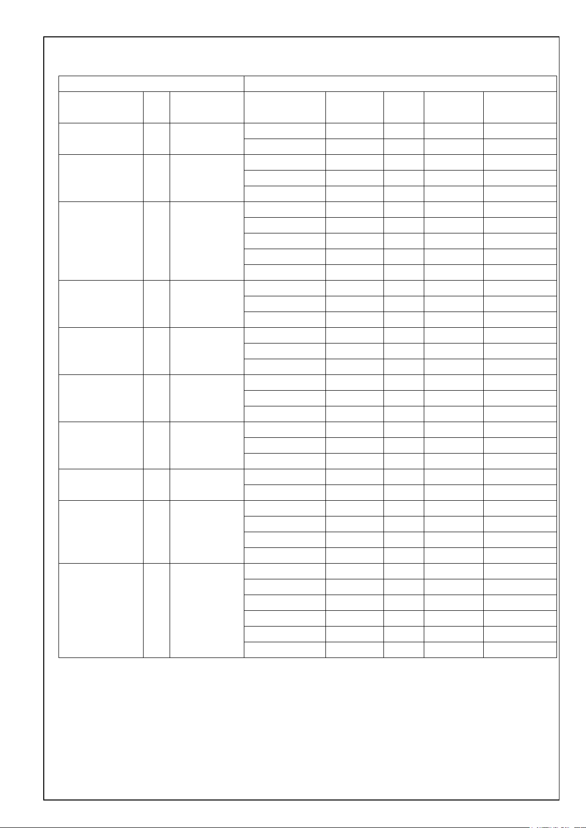
3. Product line-up
Servo driver Motor used
Model Size
Power supply
input
Model
Voltage
specification
Rated
output
Rated speed
MADLN01SE A Single MSMF5AZL1** 100 V 50 W 3000 r/min 7 cores, 23 bits
100 V MHMF5AZL1** 100 V 50 W 3000 r/min
MADLN11SE A Single MSMF011L1** 100 V 100 W 3000 r/min
100 V MQMF011L1** 100 V 100 W 3000 r/min
MHMF011L1** 100 V 100 W 3000 r/min
MADLN05SE A Single / 3 phase MSMF5AZL1** 200 V 50 W 3000 r/min
200 V MHMF5AZL1** 200 V 50 W 3000 r/min
MSMF012L1** 200 V 100 W 3000 r/min
MQMF012L1** 200 V 100 W 3000 r/min
MHMF012L1** 200 V 100 W 3000 r/min
MADLN15SE A Single / 3 phase MSMF022L1** 200 V 200 W 3000 r/min
200 V MQMF022L1** 200 V 200 W 3000 r/min
MHMF022L1** 200 V 200 W 3000 r/min
MBDLN21SE B Single MSMF021L1** 100 V 200 W 3000 r/min
100 V MQMF021L1** 100 V 200 W 3000 r/min
MHMF021L1** 100 V 200 W 3000 r/min
MBDLN25SE B Sin gle / 3 phase MSMF042L1** 200 V 400 W 3000 r/min
200 V MQMF042L1** 200 V 400 W 3000 r/min
MHMF042L1** 200 V 400 W 3000 r/min
MCDLN31SE C Single MSMF041L1** 100 V 400 W 3000 r/min
100 V MQMF041L1** 100 V 400 W 3000 r/min
MHMF041L1** 100 V 400 W 3000 r/min
MCDLN35SE C Single / 3 phase MSMF082L1** 200 V 750 W 3000 r/min
200 V MHMF082L1** 200 V 750 W 3000 r/min
MDDLN45SE D Single / 3 phase MGMF092L1** 200 V 850 W 1500 r/min
200 V MSMF092L1** 200 V 1.0 kW 3000 r/min
MDMF102L1** 200 V 1.0 kW 2000 r/min
MHMF102L1** 200 V 1.0 kW 2000 r/min
MDDLN55SE D Single / 3 phase MHMF092L1** 200 V 1.0 kW 3000 r/min
200 V MSMF102L1** 200 V 1.0 kW 3000 r/min
MGMF132L1** 200 V 1.3 kW 1500 r/min
MSMF152L1** 200 V 1.5 kW 3000 r/min
MDMF152L1** 200 V 1.5 kW 2000 r/min
MHMF152L1** 200 V 1.5 kW 2000 r/min
Encoder
specification
7 cores, 23 bits
7 cores, 23 bits
7 cores, 23 bits
7 cores, 23 bits
7 cores, 23 bits
7 cores, 23 bits
7 cores, 23 bits
7 cores, 23 bits
7 cores, 23 bits
7 cores, 23 bits
7 cores, 23 bits
7 cores, 23 bits
7 cores, 23 bits
7 cores, 23 bits
7 cores, 23 bits
7 cores, 23 bits
7 cores, 23 bits
7 cores, 23 bits
7 cores, 23 bits
7 cores, 23 bits
7 cores, 23 bits
7 cores, 23 bits
7 cores, 23 bits
7 cores, 23 bits
7 cores, 23 bits
7 cores, 23 bits
7 cores, 23 bits
7 cores, 23 bits
7 cores, 23 bits
7 cores, 23 bits
7 cores, 23 bits
7 cores, 23 bits
7 cores, 23 bits
Motor Business Unit, Panasonic Corporation
Page 6
No. SX-DSV03015 - 3 -
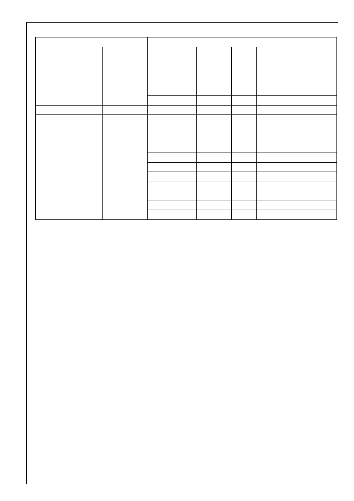
Servo driver Motor used
Model Size
Power supply
input
Model
Voltage
specification
Rated
output
Rated speed
MEDLN83SE E 3 phase MGMF182L1** 200 V 1.8 kW 1500 r/min 7 co r es, 23 bits
200 V MSMF202L1** 200 V 2.0 kW 3000 r/min 7 cores, 23 bits
MDMF202L1** 200 V 2.0 kW 2000 r/min 7 cores, 23 bits
MHMF202L1** 200 V 2.0 kW 2000 r/min 7 cores, 23 bits
MEDLN93SE E 3 phase 200 V MGMF242L1** 200 V 2.4 kW 1500 r/min 7 cores, 23 bits
MFDLNA3SE F 3 phase MSMF302L1** 200 V 3.0 kW 3000 r/min 7 cores, 23 bits
200 V MDMF302L1** 200 V 3.0 kW 2000 r/min 7 cor es, 23 bits
MHMF302L1** 200 V 3.0 kW 2000 r/min 7 cores, 23 bits
MFDLNB3SE F 3 phase MGMF292L1** 200 V 2.9 kW 1500 r/min 7 co r es, 23 bits
200 V MSMF402L1** 200 V 4.0 kW 3000 r/min 7 co res, 23 bits
MDMF402L1** 200 V 4.0 kW 2000 r/min 7 cor es, 23 bits
MHMF402L1** 200 V 4.0 kW 2000 r/min 7 cores, 23 bits
MGMF442L1** 200 V 4.4 kW 1500 r/min 7 cor es, 23 bits
MSMF502L1** 200 V 5.0 kW 3000 r/min 7 cores, 23 bits
MDMF502L1** 200 V 5.0 kW 2000 r/min 7 cor es, 23 bits
MHMF502L1** 200 V 5.0 kW 2000 r/min 7 cores, 23 bits
Encoder
specification
Motor Business Unit, Panasonic Corporation
Page 7

No. SX-DSV03015 - 4 -
Storage temperature: -20 – 65 degrees C (Max.temperature gu arantee : 80 degrees C for 72 hours no condensation*)
Height above the sea
Height above the sea level: 1000 meters or less
Vibration
5. 88 m/s2 or less, 10 – 60 Hz
Insulation voltage
Resistant to 1500 V AC between primary power supply and ground for a minute (Sensed current: 20 mA)
Control method
IGBT PWM method, sinusoidal drive
Encoder feedback
23Bit(resolution:8388608) 7cores-serial absolute encoder
Function of each multi-funct i o n i np ut is assigned by the parameter.
Function of each multi-function output is assigned by the parameter.
Analogue signal
Output
2 outputs for analog monitor
High speed line driver interface can be connected.
collector output also available for Z or EXZ signal
Communication
USB
USB interface to connect to computers for parameter setting or status monitoring.
Front panel
5 key switches, 6-digit 7-se g ment LED
Regeneration
Size A, B: External r egen resistor only Size C - F: Built-in regen resistor (External regen is also available)
Dynamic brake
Size A - F: Built-in
4. General specifications
4-1 General specification
100 V
Input
power
supply
200 V
Operation conditions
Basic specifications
Control signal
Main circuit power
Control circuit power Single phase 100 - 120 V
Main circuit
power
Control circuit
power
Temperature
Humidity Operation and storage humidity 20 - 85 % RH or less (no condensation*)
A - D
E - F 3 phase 200 - 240 V
A - D
E - F Single phase 200 - 240 V
Input
Output
Multi-function input x 10
Multi-function output x 5 + dedicated output x 1 (alarm output)
Single phase 100 - 120 V
Single/3 phase 200 - 240 V
Single phase 200 - 240 V
+ 10%
50/60 Hz
- 15%
+ 10 %
50/60 Hz
- 15 %
+ 10 %
50/60 Hz
- 15 %
+ 10 %
50/60 Hz
- 15 %
+ 10 %
50/60 Hz
- 15 %
+ 10 %
50/60 Hz
- 15 %
Operation tempera ture: 0 - 55 degrees C (no freezing)
2 inputs
Input
Pulse signal
Output
Control mode
Please note that condensation tend to occur when temperature fall.
Both open collector and line driver interface can be connected.
4 outputs
Line driver output for encoder pulses (A/B/Z signal) or external feedba c k pulses (EXA/EXB/EXZ sig nal) open
Selectable from the fo llowing 3 modes by parameter:
[1]position cont rol [2]velocity control [3]position/velocity c ontrol
Motor Business Unit, Panasonic Corporation
Page 8
No. SX-DSV03015 - 5 -
Deviation counter clear, command pulse input inhibition, command division/multiplication switching,
vibration suppression control sw itc hing, etc.
1/1000 to 8000 times
Smoothing Filter
Available
ion origin return invalidation sett ing is s et to
invalid)
Internal command velocity selection 1, Internal command velocity selection 2, Internal command velocity selection 3,
speed zero clamp, etc.
Control output
Speed arrival, etc.
0 to 10s/1000 r/min r/min Setting is possible for acceleration and deceleration respectively. S shaped
acceleration/deceleration is possible.
Velocity command filter
Available
Block operation
Not available
This function identifies the load inertia real-time and automatically sets up the gain that meets the stiffness setting
when the motor is running with ho st and inte r nal driver operation co mmands.
Overvoltage, undervoltage, overspeed, overload, overheat, overcurrent, encoder failure, positional overdeviation,
command pulse division, EEPROM failure, etc.
Control input
Control output Positioning co mpletion, etc.
Max command pulse
frequency
Command pulse input
Pulse input
Vibration suppression control Maximum of 3 may be used simultaneously
Position control
Model type vibration damping filter Maximum of 2 may be used simultaneously
2 degrees of freedom control Available
Load fluctuation suppression control Available
mode
Command pulse scaling
(Electronic gear)
500 K[pulse/s] (w hen using the photo coup ler input)
8 M[pulse/s] (when using the line receiver input of A-phase /B-phase)
Differential inp ut . D iffe rential input can be selected by parameters. ((1) Positive direction/ negative direction,
(2) A-phase/B-phase (3) Command/ direction)
Although electronic g ear rati o of the en coder resolu tion (num erator) and command number of pulses per revoluti on of the
motor (denominator) can be arbitrarily set in the range of 1 to 223 f or th e numerator and in the rang e of 1 to 223 f or the
denominator, this product should be u sed within the afor ementioned range.
Primary delay filter or FIR filter is selectable for command input.
Position compare output function
Block operation Available
Contro l i np u t
Function
Internal velocity command It is possible to switch 8 speeds of internal velocity with control input.
Soft start/down function
Speed zero clamp I nternal velocity command can be clamped to 0 with speed zero clamp input.
Velocity control
2 degrees of freedom control Available
Load fluctuation suppression control Available
Position compare output function Not available
Auto-tuning
Pulse signal output division function Number of pulses can be arbitrarily set. (However, the number of encoder pulses is the maximum number.)
Protectio n f u nction
Alarm data trace back function Reference of history of alarm data is available.
Common
Infinite rotation absolute funct ion Available
Deterioration diagnosis function Available
[Condition] Block operation valid setting
Return to origin completed state in incre me nt mo de (when block operat
4-2 Specifications by model
Refer to specification for each model.
Motor Business Unit, Panasonic Corporation
Page 9
5. Appearance and part names
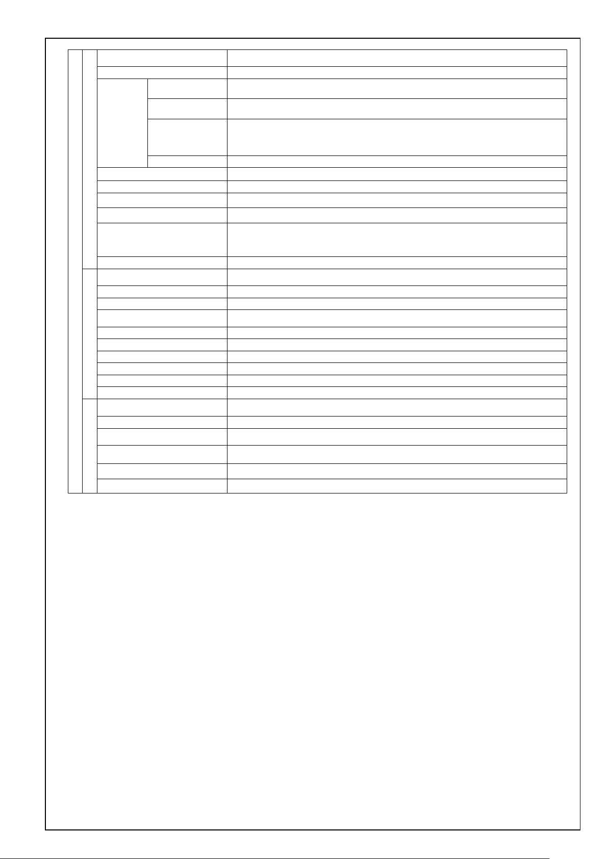
100 V,200 V size A, B
XA:Power supply input connection
05JFAT-SAXGGKK-A (JST)
(or equivalent)
Front panel
Charge lamp
XA: Power supply input
S05B-F32SK-GGXR (JST)
(or equivalent)
XB: Motor output
S06B-F32SK-GGXR (JST)
(or equivalent)
No. SX-DSV03015 - 6 -
X1:USB connection
UB-M5BR-S14-4S(LF)(SN) (JST)
(or equivalent)
XB:Motor connection
06JFAT-SAXGGKK-A (JST)
(or equivalent)
XA:Power supply input connection
XB:Motor connection
L1
L2
L3
L1C
L2C
P
N
B
U
V
W
Earth connection screw
Main power supply
input
Control power supply
input
Regenerative resistor
connection
Motor output
X6:Encoder connection
3E106-223AKV(3M)
(or equivalent)
X4:Parallel I/O connection
DF02R050NA2 (JAE)
(or equivalent)
Motor Business Unit, Panasonic Corporation
Page 10
No. SX-DSV03015 - 7 -
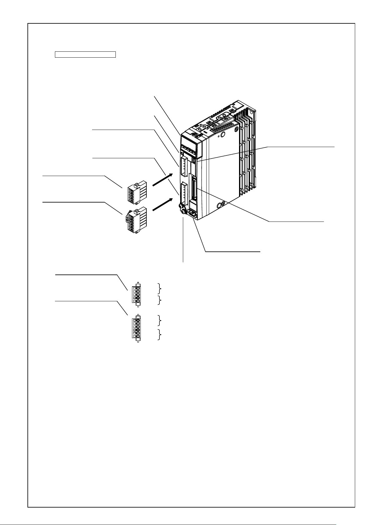
100 V,200 V size C, D
Front panel
Charge lamp
XA: Power supply input
S05B-F32SK-GGXR (JST)
(or equivalent)
XB: Motor output
S06B-F32SK-GGXR (JST)
(or equivalent)
XA:Power supply input connection
05JFAT-SAXGGKK-A (JST)
(or equivalent)
XB:Motor connection
06JFAT-SAXGGKK-A (JST)
(or equivalent)
XA:Power supply input connection
XB:Motor connection
Earth connection screw
L1
L2
L3
L1C
L2C
P
RB
B
U
V
W
Main power supply
input
Control power supply
input
Regenerative resistor
connection
Motor output
X6:Encoder connection
3E106-223AKV(3M)
(or equivalent)
X1:USB connection
UB-M5BR-S14-4S(LF)(SN) (JST)
(or equivalent)
X4:Parallel I/O connection
DF02R050NA2 (JAE)
(or equivalent)
Motor Business Unit, Panasonic Corporation
Page 11
No. SX-DSV03015 - 8 -
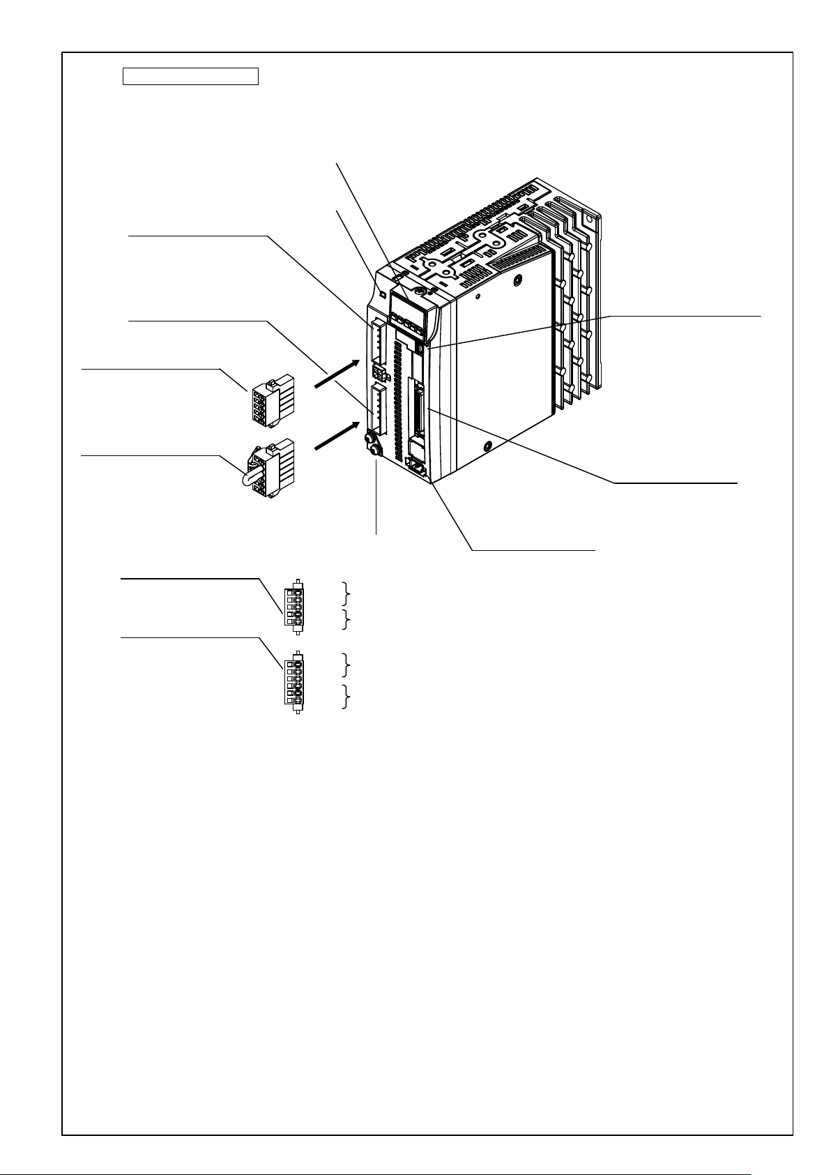
X1:USB connection
UB-M5BR-S14-4S(LF)(SN) (JST)
(or equivalent)
X4:Parallel I/O connection
DF02R050NA2 (JAE)
(or equivalent)
X6:Encoder connection
3E106-223AKV(3M)
(or equivalent)
Charge lamp
Front panel
Earth connection screw
XA:Power supply input connection
XC:Regenerative resistor connection
XB:Motor connection
XA:Power supply input connection
05JFAT-SAXGSA-L (JST)
(or equivalent)
XC:Regenerative resistor connection
04JFAT-SAXGSA-L (JST)
(or equivalent)
XB:Motor connection
03JFAT-SAXGSA-L (JST)
(or equivalent)
XA: Power supply input
S05B-JTSLSK-GSANXR (JST)
(or equivalent)
XB: Motor output
S03B-JTSLSK-GSANXR (JST)
(or equivalent)
XC: Regenerative resistor connection
S04B-JTSLSS-GSANXR (JST)
(or equivalent)
L1
L2
L3
L1C
L2C
P
RB
B
N
U
V
W
Main power supply
input
Control power supply
input
Regenerative resistor
connection
Motor output
200 V size E
Motor Business Unit, Panasonic Corporation
Page 12

No. SX-DSV03015 - 9 -
200 V size F
Front panel
Charge lamp
X1:USB connection
UB-M5BR-S14-4S(LF)(SN) (JST)
(or equivalent)
X4:Parallel I/O connection
DF02R050NA2 (JAE)
(or equivalent)
Earth connection screw
Main power supply
input
Control power supply
input
Regenerative resistor
connection
Motor output
L1
L2
L3
L1C
L2C
P
RB
B
N
U
V
W
X6:Encoder connection
3E106-223AKV(3M)
(or equivalent)
Motor Business Unit, Panasonic Corporation
Page 13

No. SX-DSV03015 - 10 -
Model number
Serial number
e.g.):
P 1 5 0 7 0 0 0 1 N
Lot number
Month of
production
Year of production
(Lower 2 digit of AD year)
Input/output voltage
Number of phase
Rated input/output
current
Input/output
frequency
Rated output of
applicable motor
QR code
standard mark
Country of
origin
Manufacture date
e.g.):
2 0 1 5 0 7 0 1
Manufacture date
Manufacture month
Manufacture year
Name plate
Motor Business Unit, Panasonic Corporation
Page 14
No. SX-DSV03015 - 11 -
Connector
pin No.
Terminal
symbol
+ 10 %
- 15 %
Use L1 and L3 terminal for single phase input
+ 10 %
- 15 %
+ 10 %
- 15 %
+ 10 %
- 15 %
When a trip happens due to a regenerative load protection error, connect
3
U
2 V 1
W
6. Configuration of connectors and terminal blocks
6-1 Power connector XA , XB , XC , XD and terminal block
[1] Size A, B of 100 V and 200 V system
XA
XB
5 L1
4 L2
3 L3 Use L1 and L3 terminal for single phase input
2 L1C
1 L2C 200 V Single phase 200-240 V
6 P
5 N
4 B
Name Description
Single phase 100-120 V
Single or 3 phase 200-240 V
an external regenerative resistor (prepared by customer) between P and
B.
U: U phase V: V phase W: W phase
Main power
supply input
Control power
supply input
Regen resistor
connection
Motor connection
Earth
100 V
200 V
100 V Single phase 100-120 V
Then, specify the extern al regenerative resistor for the parameter
Pr0.16.
Do not connect N terminal.
Connect each phase of the motor winding.
Earth terminal for grounding
50/60 Hz input
50/60 Hz input
50/60 Hz input
50/60 Hz input
* Tighten the earth screws M4 with the 0.7-0.8 Nm torque respectively.
Motor Business Unit, Panasonic Corporation
Page 15
No. SX-DSV03015 - 12 -
Connector
pin No.
Terminal
symbol
+ 10 %
- 15 %
Use L1 and L3 terminal for single phase input
+ 10 %
- 15 %
+ 10 %
- 15 %
+ 10 %
- 15 %
Normally, short out the circuit between B and RB. (Sizes C, D)
3
U
2 V 1
W
[2] Size C, D of 100 V and 200 V system
Name Description
XA
XC
XB
5 L1
Main power s upply
4 L2
3 L3 Use L1 and L3 terminal for single phase input
2 L1C
1 L2C 200 V Single phas e 200 – 240 V
4
N
3
2
P
1
6 P
5 RB
4 B
input
Control power
supply input
- Do not connect.
Regen resistor
connection
100 V
200 V
100 V Single phase 100-120 V
When a trip happens due to a re ge ner ati ve load prote c ti on e rror , o pen t h e
Then, specify the extern al regenerative resistor for the parameter
Pr0. 16.
Single phase 100-120 V
Single or 3 pha se 20 0 – 240 V
circuit between B and RB and conn ect an external regenerative resistor
(prepared by customer) bet w een P and B.
50/60 Hz input
50/60 Hz input
50/60 Hz input
50/60 Hz input
Motor connection
Earth
Connect each phase of the motor winding.
U: U phase V: V phase W: W phase
Earth terminal for grounding
* Tighten the earth screws M4 with the 0.7-0.8 Nm torque respectively.
Motor Business Unit, Panasonic Corporation
Page 16

No. SX-DSV03015 - 13 -
Connector
pin No.
Terminal
symbol
5
L1
4
L2 3 L3
2
L1C
1
L2C
3
U
2 V 1
W
[3] Size E of 200 V system
Name Description
XA
XC
XB
4 P
3 RB
2 B
1 N
Earth Earth terminal for grounding
Main power s upply
input
Control power
supply input
Regen resistor
connection
Motor connection
200 V 3 phase 200 - 240 V
200 V Single phase 200 - 240 V
Normally, short out the circuit between RB and B.
When a trip happens due to a regenerative load protection error, open the
circuit between RB and B and connect an external regenerative resisto r
(prepared by customer) between P and B.
Then, specify the external regenerative resistor for parameter Pr0. 1 6.
Do not connect N terminal.
Connect each phase of the motor winding.
U: U phase V: V phase W: W phase
+ 10 %
- 15 %
+ 10 %
- 15 %
50/60 Hz input
50/60 Hz input
* Tighten the earth screws M4 with the 0.7-0.8 Nm torque respectively.
Motor Business Unit, Panasonic Corporation
Page 17
No. SX-DSV03015 - 14 -
Terminal
bottom)
1
L1
2
L2 3 L3 4 L1C
- 15 %
5
L2C
Normally, short out the circuit between RB and B.
When a trip happens due to a regenerative load protection error, open the
7
RB 8 B
[4] Size F of 200V system
Terminal block is used instead of connector.
Terminal block
No.
(Upper to
6 P
9 N
10 U
11 V
12 W
Terminal
symbol
Name Description
Main power s upply
input
Control power
supply input
Regen resistor
connection
Motor connection
Earth
3 phase 200 - 240 V
Single phase 200 - 240 V
circuit between RB and B and connect an external regenerative resistor
(prepared by customer) b etween P and B.
Then, specify the external regenerative resistor for parameter Pr0. 16.
Do not connect N terminal.
Connect each phase of the motor winding.
U: U phase V: V phase W: W phase
Earth terminal for grounding
+ 10 %
- 15 %
+ 10 %
50/60 Hz input
50/60 Hz input
* Tighten the earth s crews M5 with the 1.4 -1.6 Nm torques respectively.
* Tighten the terminal block screws M5 with the 1.0-1.7 Nm torques respectively.
* Tighten the fixin g s crew M3 for the terminal block cover with the 0.2 Nm torque.
* If the maximum value of tightening torque is exceeded, the terminal block could be damaged.
Motor Business Unit, Panasonic Corporation
Page 18
No. SX-DSV03015 - 15 -
Connector
6-2 USB connector X1
By connecting to a computer or a controller via USB interface, the following operations are available
parameter reference / change parameter save / load monitoring of status checkin g ala rm status or alarm history
Name Symbol
VBUS 1
USB signal
D+ 3
For manufacturer use
Signal ground GND 5 Signal ground
−
pin No
Communicate with a computer or a controller D- 2
4 Do not connect
Description
Motor Business Unit, Panasonic Corporation
Page 19

nector
pin No.
Multi-function input 1
SI1
8
Multi-function input 2
SI2
9
Multi-function input 3
SI3
26
Multi-function input 4
SI4
27
Multi-function input 5
SI5
28
SI6
29
SI7
30
SI8
31
Multi-function input 9
SI9
32
Multi-function input 10
SI10
33
Name
Symbol
Description
When turned ON, the servo is turned on (power is supplied to the motor).
Po sitive overtravel limit.
Negative overtravel limit.
When this input is OF F, a ne ga tiv e tor que doe s not occ ur.
Deviation counter clear
CL
Clears the position deviation counter.
Command pulse inhibition
INH
Ignores the position comm a nd pul se.
Preset velocity 1
INTSPD1
Preset velocity 2
INTSPD2
Preset velocity 3
INTSPD3
Speed zero clamp
Sets the speed command to zero.
Anti-vibration switch 1
Anti-vibration switch 2
Gain switch
GAIN
Input to switch the gains.
Torque limit switch
TL-SEL
Switches the torque limits.
Alarm clear
A-CLR
Digital input to clear the alarm.
Command scaling switch
VC-SIGN
Specifies the sign of the speed command during the speed control.
Torque comm a nd sig n
TC-SIGN
Specifies the sign of the torque command during the torque control.
Command scaling switch 1
DIV1
Switches the scaling numerators of the command pulse.
Allows you to switch up to 4 numerators by combining DIVs 1, 2.
Command sca ling sw i tch 2
DIV2
Forced alarm input
E-STOP
Generates Err87. 0 "Abnormal forced alarm input."
Inertia ratio switch
Switches the inertia ratios.
6-3 Parallel I/O connector, X4
Common digital inputs
Name Symbol
Power supply input COM+ 7
Con
-
Description Circuit
・Connect to the + terminal of an external DC power supply (12 to 24 V)
・Use a 12 V (±5 %) to 24 V (±5 %) power supply
・Insulat ion i s needed against the prim ary s ide pow e r sup ply .
Please do not connect th em wit h the same power supply.
No. SX-DSV03015 - 16 -
Multi-function input 6
Multi-function input 7
Multi-function input 8
Functions allocatable to multi-function inputs
Servo ON SRV-ON
Control mode switch
Positive overtravel limit
Negative overtravel limit
C-MODE
POT
NOT
The function changes according to the parameter settin gs. See below. i-1
When turned OFF, t he s er vo is t urn ed of f a nd the m otor p ow er i s tur ne d of f .
Switches the contr ol m ode s.
Make sure to connect this so that the contact point will be opened when the movable
module positively exceeded the movable range.
When this input is OF F, a pos it ive t orq ue does no t occ ur .
Make sure to wire this input to be activated as the work over travels the limit in the
negative direction.
Preset s peed.
Allows you to set up t o 8 int er na l ve loci tie s by com bi ning I NT SPDs 1 - 3.
ZEROSPD
VS-SEL1
VS-SEL2
Switches the appli e d fr eque nc ies f or anti-vibration control.
J-SEL
Motor Business Unit, Panasonic Corporation
Page 20

No. SX-DSV03015 - 17 -
Con
pin No.
Command direction
Con
Pin No.
kpps for line driver input, and
Command direction
Input signals (command pulse train) and their functions
A suitable interface can be chosen from two kind of interface based on the specification of command pulses.
A. Pulse train interface with line driver
Command pulse
input 1
input 1
Command pulse
input 2
input 2
Name Symbol
PULSH1 44
PULSH2 45
SIGNH1 46
SIGNH2 47
-nector
Input t er min al for the position command pulse. It can be select ed by setting
corresponding parameters.
Disabled in such control modes as the speed control or the torque control,
which does not require position commands.
The maximum allowable input frequency is 8 Mpps.
B. Pulse train interface with optocoupler
Name Symbol
OPC1 1
PULS1 3
PULS2 4
OPC2 2
SIGN1 5
-nector
Input t er min al for the position command pulse. It can be selected by setting
corresponding parameters.
Disabled in such control modes as the speed control or the torque control,
which does not require position commands.
The maximum allowable input frequency is 500
200 kpps for open collector input.
Description Circuit
Di-2
Description Circuit
Di-1
SIGN2 6
Motor Business Unit, Panasonic Corporation
Page 21
Con
pin No.
SO1-
SO1+
10
11
SO2-
34
SO4-
SO4+
38
39
ALM-
36
Multi-function outp ut 5
SO5
12
Multi-function outp ut 6
SO6
40
The power capacity varies depending on a composition of I/O circuit.0.5A
Name
Symbol
Description
Servo alarm
ALM
Digital output to indicate the driver is in alarm status..
Motor holding break releas e
BRK-OFF
Digital output to provide the timing signal to control the motor holding brake.
Zero speed
ZSP
Outputs the zero speed detection signals.
Torque limited
TLC
Outputs the torque limit signal.
In-position
INP
Outputs the positioning completion signal.
At speed
AT-SPD
Outputs the at-speed signal.
V-COIN
V-COIN
Outputs the speed coincidence signal.
Outputs the warning output signal configured in Pr4. 40 "Warning output
selection 1".
Outputs the warning output signal configured in Pr4. 41 "Warning output
Position command ON/OFF
P-CMD
Outputs meaning positional command applied.
Speed in –limit output
V-LIMIT
Outputs meaning the speed is limited at torque control mode.
Alarm attribute output
Output s meani ng occur an alarm that can be cleared.
Turns on output transistor when the speed command is applied while the speed is
Servo on status output
SRV-ST
Turn on output transistor when servo is on.
Output signals (Common) and their functions
Name Symbol
Multi-function outp ut 1
-nector
No. SX-DSV03015 - 18 -
Description Circuit
Multi-function outp ut 2
Multi-function output 4
Servo alarm
Power supply input
SO2+
ALM+
COM- 41
The function changes according to the parameter settin gs. See below.
35
Digital output to indicate alarm status.
37
The function changes according to the parameter settin gs. See below. o-3
・Connect to the - terminal of an external DC power supply (12 to 24 V)
・
or more is recommended.
・Insulat ion i s needed against the prim ary s ide pow e r sup ply
Please do not connect the m w ith t he sa m e pow e r supply.
Functions allocatable to multi-function outputs
Servo ready S-RDY Digital output to indicate the driver is ready to be enabled.
Positioning comple tion 2 INP2 Outp uts the positioning completion signal 2.
Warning output 1 WARN1
o-1
Warning output 2 WARN2
Speed command ON/OFF V-CMD
ALM-ATB
selection 2".
controlled.
Motor Business Unit, Panasonic Corporation
Page 22

Connector
Connector
Pin No.
Pin No.
50,
shell
Sign a l ground
Internally insulated from the control signal power supply (COM-).
Do not conne ct
Output signals (Pulse output) and its function
Name Symbol
A phase output
B phase output
Z phase output
Z phase output CZ 19
pin No.
OA+ 21
OA- 22
OB+ 48
OB- 49
OZ+ 23
OZ- 24
No. SX-DSV03015 - 19 -
Description Circuit
Scaling processed encoder signal or external scale signal ( A/B/Z-phase) is
output in differential mode. (RS422 equivalent)
Scaling ratio can be set by parameters.
The ground pin of the line driver on the output circuit is not insulated and is
connected to signal ground (GND).
The maximum output frequency is 8 Mpps (after quadrature).
Open collector output of Z-phase signal.
Ground of line driver of the output circuit is connected to signal ground
(GND); not insulated.
Do-1
Do-2
Analog monitor signals and their functions
Name Symbol
Analog monitor output
Others
Name Symbol
Frame ground FG
Signal ground GND
−
IM 42
SP 43
Connector
13,15,
17,25
−
20
Description Circuit
Analog signal output for monitoring
Monitoring object changes according to the parameter setting.
Description Circuit
Internally connected to the earth terminal.
Ao-1
Motor Business Unit, Panasonic Corporation
Page 23

No. SX-DSV03015 - 20 -
Connector
pin No.
1
E5V 2 E0V (*Note 1)
3
Do not connect.
4
Do not connect.
Encoder signal I/O
(serial signal)
5
PS
6
/PS
Frame ground
shell
FG
6-4 Encoder connector X6
Name
Encoder power supply output
-
*Note 1) The E0V of the encoder power supply output is connected with the control circuit ground of the connector X4 .
Description
Motor Business Unit, Panasonic Corporation
Page 24

No. SX-DSV03015 - 21 -
o - 1
Do - 2
Di - 1
Ao - 1
V
DC
12 to 24 V
4.7 k
4.7 k
or
1 k
1 k
1000 p
1000 p
V
DC
12 to 24 V
Pins;
S:(X4) 8,9,26,27,28,29,30,31,32,33
P:(X4) 7
P
P
S
S
Pins;
+:(X4)11,35,37,39 -:(X4)10,34,36,38
Note) To directly run the relay, attach a diode in
Parallel with the relay and in the direction
shown in the figure above.
VCE sat = 1.2 V
50 mA
or less
R
10
V
DC
12 to 24 V
+
-
GND
1 k
Pins;
+: (X4) 42,43
-: (X4) 13,17,25
Note)Outputting signal amplitude is ±10 V
+
-
Twisted pair
220
GND
13
4,6
3,5
SIGN
PULS
H/L
H/L
220
GND
13
4,6
3,5
10 mA
R
Vp
12 to 24 V
SIGN
PULS
L/H
ON/OFF
1,2
2.2 k
220
GND
13
4,6
3,5
24 V
SIGN
PULS
L/H
ON/OFF
1,2
2.2 k
2.2 k
1000 p
2.2 k
1000 p
2.2 k
1000 p
<Line Driver>
<Open Collector>
①12-24 V Powersupply with external resistor
②24 V Power supply without external resistor
Vp-1.5
R+220
≒10 mA
Twisted pair
Equivalent of
AM26C31
GND
13
Pins;
+:21,23,48
-:22,24,49
+
-
Twisted pair
CZ
V
DD
30 V MAX
50 mA MAX
GND
17
19
10
Input and output interface
i - 1
Do - 1
Motor Business Unit, Panasonic Corporation
Page 25

Di - 2
Equivalent of
AM26C32
20 k
20 k
2 k
2 k
120
Twisted pair
H/L
13
GND
45
H/L
PULS
SIGN
44
47
46
Pins;
+:40,12
Note) To directly run the relay, attach a diode in
Parallel with the relay and in the direction
shown in the figure above.
50 mA
or less
R
10
V
DC
12 to 24 V
+
41
o-2
No. SX-DSV03015 - 22 -
Motor Business Unit, Panasonic Corporation
Page 26

7. Dimensions
External dimension size A
[Base-mounting TYPE (Standard: Mounting on the back)]
No. SX-DSV03015 - 23 -
2-M4 Effective screw depth 7
Name
plate
*Please do not use the screw holes of no description of the size value.
2-M4 Effective screw depth 7
Motor Business Unit, Panasonic Corporation
Page 27

[Rack-mounting TYPE (Option: Mounted on the front)]
Mounting bracket (Option)
No. SX-DSV03015 - 24 -
Name
plate
Mounting bracket (Option)
*Please do not use the screw holes of no description of the size value.
*Mounting bracket is optional parts. Mounting bracket does not shipped with the product.
Motor Business Unit, Panasonic Corporation
Page 28

No. SX-DSV03015 - 25 -
External dimension size B
[Base-mounting TYPE (Standard: Mounting on the back)]
2-M4 Effective screw depth 6.5
Name
plate
*Please do not use the screw holes of no description of the size value.
2-M4 Effective screw depth 7
Motor Business Unit, Panasonic Corporation
Page 29

[Rack-mounting TYPE (Option: Mounted on the front)]
Mounting bracket (Option)
No. SX-DSV03015 - 26 -
Name
plate
Mounting bracket (Option)
*Please do not use the screw holes of no description of the size value.
*Mounting bracket is optional parts. Mounting bracket does not shipped with the product.
Motor Business Unit, Panasonic Corporation
Page 30

No. SX-DSV03015 - 27 -
External dimension size C
[Base-mounting TYPE (Standard: Mounting on the back) ]
2-M4 Effective screw depth 6.5
Name
plate
*Please do not use the screw holes of no description of the size value.
2-M4 Effective screw depth 6
Motor Business Unit, Panasonic Corporation
Page 31

[Rack-mounting TYPE (Option: Mounted on the front)]
Mounting bracket (Option)
No. SX-DSV03015 - 28 -
Name
plate
Mounting bracket (Option)
*Please do not use the screw holes of no description of the size value.
*Mounting bracket is optional parts. Mounting bracket does not shipped with the product.
Motor Business Unit, Panasonic Corporation
Page 32

No. SX-DSV03015 - 29 -
External dimension size D 200V
[Base-mounting TYPE (Standard: Mounting on the back)]
2-M4 Effective screw depth 6.5
Name
plate
*Please do not use the screw holes of no description of the size value.
2-M4 Effective screw depth 6
Motor Business Unit, Panasonic Corporation
Page 33

Mounting bracket (Option)
Mounting bracket (Option)
Name
plate
[Rack-mounting TYPE (Option: Mounted on the front)]
No. SX-DSV03015 - 30 -
*Please do not use the screw holes of no description of the size value.
*Mounting bracket is optional parts. Mounting bracket does not shipped with the product.
Motor Business Unit, Panasonic Corporation
Page 34

No. SX-DSV03015 - 31 -
External dimension size E 200V
[Rack-mounting TYPE (Standard)]
4-M4 Effective screw depth 6
Name
plate
4-M4 Effective screw depth 6
Motor Business Unit, Panasonic Corporation
Page 35

[Base-mounting TYPE (Change from standard)]
No. SX-DSV03015 - 32 -
Name
plate
Motor Business Unit, Panasonic Corporation
Page 36

No. SX-DSV03015 - 33 -
External dimension size F 200V
[Rack-mounting TYPE (Standard)]
4-M4 Effective screw depth 9
Name
plate
4-M4 Effective screw depth 9
Motor Business Unit, Panasonic Corporation
Page 37

[Base-mounting TYPE (Change from standard)]
No. SX-DSV03015 - 34 -
Name
plate
Motor Business Unit, Panasonic Corporation
Page 38

No. SX-DSV03015 - 35 -
Maximum
cable length
Main power supply
L1, L2, L3
Refer to specification
Control power supply
L1C, L2C
Refer to specification
Encoder connection
X6
20m
Batch twisted shielded pair
Core cable: 0.18mm2 or more
I/O connection
X4
3m
Solder plug
(soldering type)
8. Wiring
8-1 Used cables and maximum cable lengths
Name
Motor connection
Earth cable
Symbol
Used cable
U, V, W, 20m Refer to specification
Refer to specification
8-2 Various connectors
Connector symbol Part name Part number Manufacturer
DF02P050F22A1
X4
JAE
Shell kit DF02D050B22A
X6 Connector 3E306-3200-008 3M Company
Please use the above part number connector, or equivalent connector.
Motor Business Unit, Panasonic Corporation
Page 39

No. SX-DSV03015 - 36 -
L1
L2
L3
L
ON
MC1
OFF
ALM
Coli surge suppression units
L1C
L2C
P
MC
U
V
W
motor
ALM+
ALM-
ALM
Main power
supply
Control power
supply
Motor
connection
MCCB
37
36
Built-in thermostat of an external
regenerative resistor (light yellow)
B
Red
White
Green or
Green/Yellow
Insulated
DC12 to 24 V
(±5 %)
+
-
Noise filter
N
External
regenerative
resistor
XA
XB
X4
*When you use single phase,
connect the main power
between L1 and L3 terminals.
Power supply
(3-phase)
Black
In case of using the external
regenerative resistor
In case of not using the external
regenerative resistor
Between P and B:
regenerative resistor.
8-3 Precautions for wiring
(1) Wiring to power connector and terminal block
100/ 200 V sizes A - B
■Connection of regenerative resistor
Shorting
Size
cable
regenerative
(Accessories)
A
B
Not attached
installed
- The circuit con nected to term inal X1 – X6 are secondary circuits.
Insulation is needed against the prim ary si de pow er su pply (powe r su pply of the m otor bra ke) .
Please do not connect them with the s ame power su pply.
Internal
resistor
Not
Connect the external
Connection of the connector XB
Between P and B:
Keep open
Motor Business Unit, Panasonic Corporation
Page 40

No. SX-DSV03015 - 37 -
In case of using the external
regenerative resistor
In case of not using the external
regenerative resistor
Between RB and B:
regenerative resistor
100/ 200 V sizes C - D
Built-in thermostat of an external
regenerative resistor (light yellow)
Power supply
(3-phase)
*When you use single phase,
connect the main power
between L1 and L3 terminals.
MCCB
Noise filter
Insulated
DC12 to 24 V
(±5 %)
Short cable
External
regenerative
resistor
motor
+
-
ON
MC
Red
White
Black
Green or
Green/Yellow
ALM
OFF
ALM
Coli surge suppression units
L
L1
L2
L3
L1C
L2C
P
N
P
RB
B
U
V
W
37
ALM+
36
ALM-
XA
Main power
supply
Control power
supply
XC
XB
Motor
connection
X4
MC1
■Connection of regenerative resistor
Shorting
Size
cable
(Accessories)
C
D
Supplied Installed
- The circuit con nected to term inal X1 – X6 are secondary circuits.
Insulation is needed against the pr im ary si de pow er s upply (powe r su pply of the m otor bra ke) .
Please do not connect them with the s ame power su pply.
Internal
regenerative
resistor
Disconnect the short cable
Between P and B:
Connect the external
Connection of the connector XB
Between RB and B:
Connect the shorting cable
Motor Business Unit, Panasonic Corporation
Page 41

No. SX-DSV03015 - 38 -
In case of using the external
regenerative resistor
In case of not using the external
regenerative resistor
Between RB and B:
regenerative resistor
200 V size E
Built-in thermostat of an external
regenerative resistor (light yellow)
Power supply
(3-phase)
MCCB
ON
Noise filter
Short cable
External
regenerative
resistor
Red
White
Black
Green or
Green/Yellow
motor
Insulated
DC12 to 24 V
(±5 %)
+
-
ALM
MC
OFF
ALM
Coli surge suppression units
L
L1
Main power
L2
supply
L3
L1C
Control power
supply
L2C
P
RB
B
N
U
Motor
V
connection
W
37
ALM+
36
ALM-
XA
XC
XB
X4
MC1
■Connection of regenerative resistor
Shorting
Size
cable
(Accessories)
E Supplied Installed
- The circuit con nected to term inal X1 – X6 are secondary circuits.
Insulation is needed agains t the prim ary s ide pow er s upply ( po w er su pply of the m otor brak e).
Please do not connect them with the s ame power su pply.
Internal
regenerative
resistor
Disconnect the short cable
Between P and B:
Connect the external
Connection of the connector XC
Between RB and B:
Connect the shorting cable
Motor Business Unit, Panasonic Corporation
Page 42

No. SX-DSV03015 - 39 -
L1
L2
L3
L
ON
MC1
OFF
ALM
L1C
L2C
P
MC
U
V
W
Motor
ALM+
ALM-
ALM
MCCB
37
36
+
-
RB
X4
N
B
Short bar
Noise filter
Power supply
(3-phase)
Built-in thermostat of an external
regenerative resistor (light yellow)
Coli surge suppression units
Main power
supply
Control power
supply
Motor
connection
External
regenerative
resistor
Red
White
Black
Green or
Green/Yellow
Insulated
DC12 to 24 V
(±5 %)
In case of using the external
regenerative resistor
In case of not using the external
regenerative resistor
Between RB and B:
regenerative resistor
200 V size F
■Connection of regenerative resistor
Internal
regenerative
resistor
Size
Short bar
(Accessories)
F Supplied Installed
-The standard of the ability of the built-in dynamic brake resistor is up
to continuousness three times in the stop from the allowance and maximum inertia and the rated speed.
Resistor is damaged and the dynamic brake might not work when using it under more critical operating condition.
- The circuit con nected to term inal X1 – X6 are secondary circuits.
Insulation is needed against the primary side pow er su pply (power su pply of the m otor bra ke).
Please do not connect them with the s ame power su pply.
Disconnect the short bar
Between P and B:
Connect the external
Connection of the connector XC
Between RB and B:
Connect the short bar
Motor Business Unit, Panasonic Corporation
Page 43

No. SX-DSV03015 - 40 -
[1] When the servo driver uses single p hase power supply for sizes A - D, co nnect the servo driver to the
terminals L1, L3 of main power supply i nput. Do not connect anything to the terminal L2.
[2] Surely insert the co nnector into place until it clicks.
[3] Make sure to use an insulation coated crimp terminal when connecting to each terminal on the terminal
block.
[4] Te rminal b lock co ver i s fixe d wit h scre ws. W hen wirin g to the ter minal b loc k, unscr ew t hese scre ws to
uncover the cover. Tighten the c over fixing screw with the torque of 0.2 Nm or less.
[5] To not use an external regenerative resistor, short out th e circuit between terminals RB and B. (For sizes C,
D, E, F)When a trip occurs due to the regenerative load protection error No.18.0, externally install a
regenerative resistor.
To externally install a regenerative resistor, remove a connection cable between terminals RB, B and then
connect the regenerative resistor between terminals P, B.
The products (Sizes A, B) supporting only the external regenerative resistor, connect an external
regenerative resistor if necessary.
To use an external regenerative resistor, se t Pr.0.16 (external regenerative resistor selection) to 1 or 2.
[6] Apply the power supply of the voltage indicated on the nameplate.
[7] Do not reverse-connect the power input terminals (L1, L2, and L3) and the motor output terminals (U, V,
and W).
[8] Do not connect the motor output terminals (U, V, and W) to ground or short out them.
[9] Because high voltage is applied to the power connectors XA , XB , XC , and XD , a nd the ter mina l
block, never touch them on any ac count. It may cause electric shock.
[10] Suitable for use on a circuit capable of delivering n ot more than 5000 rms symmetrical amperes, below the
maximum input voltage of the product.
[11] An AC servomo tor, unl ike an i nducti on moto r, ca nnot cha nge the rotat ion dir ectio n by exchanging three
phases.
Make sure to coincide the motor output terminals (U, V, and W) of the servo driver with the colors
(pin number for cannon plugs) of the motor output cables.
[12] Surely connect the ground terminals of the motor and the servo driver and earth the ground terminal as well
as that of the noise filter. In addition, earth the equipment unit. To earth them, ground resistance should be
100 ohm or less for grounding.
When the power supply voltage is over 300 V ground resistance should be 10ohm or less.
Please tight the earth screws by appropriate torque and use correct size earth cable decided in the
specifications.
In order to avoid the impact of electrolytic corrosion, do not immediately have any contact between
aluminum and copper.
[13] Attach the serge absorbing circuits for preventing n oises to an electromagnetic contactor placed around the
servo driver, a coil between relay contact points, and a brake winding of motor with a brake.
[14] Attach the no fuse breaker. In case of emergency, make sure to power off outside the servo driver. To use
an earth leakage circuit breaker, use that in which a high frequency wave c ountermeasure is taken.
[15] In order to reduce the terminal noise voltage, install a noise filter.
[16] Customer is responsible for the power supply of the brake attached to a motor.
[17] Turn ON the power after the wiring was finished.
Motor Business Unit, Panasonic Corporation
Page 44

No. SX-DSV03015 - 41 -
Input power voltage
Single phase
100 V
A
DV0P4280
DV0P4281 (100 W or less), DV0P4283 (20 0 W)
B
DV0P4283
DV0P4283
C
DV0P4282
DV0P4283
D
DV0P4284
F
DV0P4285 x 2 in parallel
Built-in thermal protector
operational temperature
Manu
model
Free air
Fan used
(1 m/s)
Ω [W]
[W]
DV0P4280
RF70M
50
10
25
140 ± 5 deg. Celsius
DV0P4281
RF70M
100
10
25
Contact point B
Open/close capacity (resistance
load)
DV0P4283
RF180B
50
17
50
1 A 125 VAC, 6000 times
DV0P4284
RF240
30
40
100
0. 5 A 250 VAC, 10000 times
DV0P4285
RH450F
20
52
130
* As for external regenerative resistor, we recommend the resistors below:
Size
E
-
Single/3 phase 2 00 V
DV0P4284 x 2 in parallel
or
DV0P4285 x 1
Manufacturer by Iwaki Musen K enkyusho
Specification
Part number
DV0P4282 RF180B 25 17 50
-facturer's
Resis
-tance
value
Rated power
(for reference) *
* Electric power available without running the built-in thermal protector.
For safety, a temperature fuse and a thermal protector are built in.
Configure the circuit so as to tur n off the power supply when the thermal protector is running.
The built-in temperature fuse can break according to the radiation condition, the used temperature range, the
power supply voltage, and the load change.
Make sure that the surface temperature of regenerative resistor is being kept 100 deg. Celsius or less under
bad conditions (high power supply voltage, large load inertia, short deceleration time, etc.) subject to
regeneration by embedding the regenerative resistor in equipments and running the equipments.
Attach the regenerative resistor on the incombustibles such as metal.
Install the regenerative resistor so that people can not directly touch it, such as the incombustible to cover it.
Keep the temperature of places, which people can directly touch, below 70 deg. Celsius.
Motor Business Unit, Panasonic Corporation
Page 45

No. SX-DSV03015 - 42 -
d Sizes A-F
10 mm or more
*) Dynamic brake
Servo driver(size A-F) has built-in dynamic brake function to stop motor in an em ergency.
Dynamic brake can be operated in the f ollowing cases
1. The m ain power off
2. The servo off
3. Protection action
4. Connector X4 driv in g ban import ati on ( PO T, NO T) acti on
On the above 1~4 cases, valid or inv alid of dyn amic brake can be determ in ed by the parameters .
However, when the control power off, dynamic brake of size A-F keep valid condition.
Dynamic brake shall be using in rated short time for emergency stop using. Please note the following points.
1. Do not start / stop the motor by the servo signal (SRV-ON) . Built-in dynamic brake circuit may be damag ed.
2. Do not drive the motor with external torque. Motor generates electricity by external torque.
Dynamic brake circuit will be damaged and it is possible that short-circuit current cause smok e or com bust ion.
3. Allow approx. 10 minutes pause when the dynamic brake is activated during high-speed running.
Resistor is damaged and the dynamic brake might not work when using it under more critical o perating
condition.
*) Mounting direction and spacing
-To perform effectiv e cooling, allow suff icient ambien t space.
-Provide a fan so as to m ake uniform t he tem perature in the control panel.
-Each of Sizes D to F is equipped with a cooli ng fan on t he bot tom .
-Adhere to environmental conditions for the environment in the control panel.
Fan
40mm
or
more
In case the portion to receiv e a f an is coated , peelin g off the coat ing before ins talling a f an or usin g hom ebuilt bracket
s with conductive plating provides eff ective ant i-noise measures.
d d
Direction of air flowing from
the internal cooling fan (Sizes D – F)
Control panel
Fan
d
100mm
or more
40mm
or
more
100mm
or more
Motor Business Unit, Panasonic Corporation
Page 46

No. SX-DSV03015 - 43 -
(2) Wiring to connector X4
[1] Customer is responsible for the control signal power supply at 12-24 VDC for external control connected
between COM+ and COM-.Insulation is needed against the primary side power supply (power supply of
the motor brake).
Please do not connect them with the same power supply.
[2] Place the servo driver and its peripheral device as nearly as possible (up to 3 m) so as to shorten the wiring.
[3] Wire the wiring as far away as possible (30 cm or more) from the power lin es (L1, L2, L 3, L1C, L2C, U, V ,
W,
). Do not p ut them in the same duct or bind them together.
Digital input
7
33
30
29
27
28
26
32
31
9
8
COM+
4.7 kΩ
INH
CL
SRV-ON
GAIN
DIV1
VS-SEL1
C-MODE
A-CLR
POT
NOT
V
DC
12 to 24 V
Command pulse
Inhibition input
Deviation counter
clear input
Servo-ON input
Gain switching input
Electronic gear
switching input 1
Damping control
switching input 1
Control mode
switching input
Alarm clear input
Positive direction
Over-travel inhibition input
Negative direction
Over-travel inhibition input
The functions of pins 8, 9, 26-33 are allocatable with parameters. The figure above shows the default setting.
Motor Business Unit, Panasonic Corporation
Page 47

No. SX-DSV03015 - 44 -
[4] Be aware of the polarity of the power supply for control signals. The polarity connection contrary to the
figure shown above can damage the servo driver.
[5] To directly drive the relay with each output signal, make sure to attach a diode in parallel to the relay and in
the direction as shown in the figure below. The servo driver can be dam aged if the diode is n ot attached or
the diode is attached in the oppo site direction.
[6] When a logic circuit such as a gate receives each output signal, take care so that a n oise doe s n ot im pact on
the circuit.
[7] Apply 50 mA or less of current to each output.
Digital output
35
34
37
36
39
38
11
BRKOFF+
10
BRKOFF-
40
S-RDY+
S-RDY-
ALM+
ALM-
AT-
SPEED+
AT-
SPEED-
TLC
V
DC
12 to 24 V
Servo-ready output
Servo-alarm output
At-speed output
External brake
release output
Torque in-limit output
Zero speed detection output
12
41
ZSP
COM-
The functions of pins 10, 11, 34, 35, 38, 39 are allocatable with parameters. The figure above shows the
default setting.
Motor Business Unit, Panasonic Corporation
Page 48

No. SX-DSV03015 - 45 -
PULS
44
45
46
47
13
represents twisted pair
120 Ω
2 kΩ
2 kΩ
20 kΩ
20 kΩ
120 Ω
2 kΩ
2 kΩ
20 kΩ
20 kΩ
SIGN
Pulse train command
A. Pulse train interface exclusively for line driver
B. Pulse train interface
The pulse train command input can support both line driver and open collector interfaces, but in order to
increase the certainty of signal transmissions, we recommend you to use the pulse train command input as an
line driver interface as shown in the figure below.
Be aware that the line driver and open collector interfaces differ from each other in the connection to the servo
driver.
Line driver interface
PULS1
3
4
5
6
13
PULS2
SIGN1
SIGN2
2.2 kΩ
220 Ω
2.2 kΩ
220 Ω
represents twisted pair
Motor Business Unit, Panasonic Corporation
Page 49

No. SX-DSV03015 - 46 -
1
4
2
6
13
OPC1
2.2 kΩ
220 Ω
PULS2
2.2 kΩ
OPC2
SIGN2
24 V
DC
2.2 kΩ
220 Ω
2.2 kΩ
represents twisted pair
Open collector interface
V
DC
- 1.5
R + 220
≒ 10 mA
3
PULS1
2.2 kΩ
13
4
5
6
PULS2
220 Ω
SIGN1
SIGN2
220 Ω
2.2 kΩ
R
V
DC
R
represents twisted pair
Note: Precautions for using the command pulse input as an open collector interface
Shorten the wire length (up to 1 m).
Be aware that the maximum pulse frequency of the open collector interface is small (200 kpps)
compared with that (500 kpps) of the line driver interface.
Motor Business Unit, Panasonic Corporation
Page 50

No. SX-DSV03015 - 47 -
Feedback pulse of rotary encoder
AM26LS32
(or equivalent)
AM26LS31
(or equivalent)
OA+
OA-
OB+
OB-
OZ+
OZ-
GND
21
22
48
49
23
24
25
A
Max. rating 30 V,
B
Z
High speed photo-coupler
1925CZ
GND
50 mA
TLP554
(or equivalent)
Connect signal ground of the host
and the driver without fail.
represents twisted pair
Note:
[1] As well as being output in the line driver, only the Z-phase signals are output to the pin 19 (CZ) in the
open collector. When using this CZ signal, be careful not to be subject to the noise impact.
[2] Use a line receiver (AM26C32 or equivalent) for receiving the output pulses. Then, attach ppropriate
terminating resistor between inputs of the line receiver.
[3] In the Z-phase signal output, be aware that the logic of line driver output (OZ) is the reverse of that of
the open collector output (CZ).
[4] Use the pulses at less than or equal to the maximum output frequency 4 Mpps (after quad edge
valuation).
Motor Business Unit, Panasonic Corporation
Page 51

No. SX-DSV03015 - 48 -
172169-1
Tyco Electronics
(or equivalent)
Motor side
Encoder cable
Driver side
E0V
BAT+
BAT-
PS
PS
FG
E5V
E0V
PS
PS
Shell (FG)
+5 V
0 V
1
2
3
4
5
6
7
8
1
2
4
5
3
Twisted pair
Regulator
172161-1
Tyco Electronics
(or equivalent)
E5V
Motor
White
Black
Red
Pink
Cyan
Purple
Yellow/Green
E5V
JL10-2A20-29P
JAE
(or equivalent)
Motor
Encoder cable
Driver side
E0V
BAT+
BAT-
PS
PS
FG
E5V
E0V
PS
PS
Shell (FG)
+5 V
0 V
1
2
3
4
5
6
H
G
T
S
K
L
J
Twisted pair
Regulator
JL10-6A20-29S-EB
N/M3057-12A
JAE
(or equivalent)
(3) Wiring to connector X6
[1] As for the e ncoder cable, use the batch shielded twisted wire pairs whose core is 0.18 mm2 or more.
[2] The cable length should be up to 20 m. When the wiring is long, we recommend you to use the double wiring
for the 5 V power supply in order to reduce the impact of voltage drop.
[3] Connect the coat of shielded cable at the motor side to the shield of shielded cable from the encoder.
Make sure to connect the coat of shielded cable at the servo driver side to the shell (FG) of X6 .
[4] Wire the wiring as far away as possible (30 cm or more) from the power lines (L1, L2, L3, L1C, L 2C, U, V, W,
).
Do not put them in the same duct or bind them together.
[5] Do not connect anything to the empty pins of X6 .
In case of using as singleturn encoder
In case of lead wire type:
In case of canon plug type:
Motor Business Unit, Panasonic Corporation
Page 52

No. SX-DSV03015 - 49 -
CSA standard
C22. 2 No. 14
KN11
KN61000-4-2,3,4,5,6,8,11
9. Compliance with global standards
9-1 Conforming standards
EN55011
European EC
EMC directive
directive
Low voltage directive
UL standard UL508C (File No. E164620)
KC
EN61000-6-2
EN61000-6-4
EN61800-3
EN61800-5-1
EN50178
IEC : International Electrotechnical Commissio n
EN : Europa i s chen Norman
EMC : Electromagnetic Compatibility
UL : Under writers Laboratoris
CSA : Canadian Standards Association
KC : Radio Waves Act(South Korea)
9-2 European EC directive
Our products, in orde r to make it easy for th e embedded equ ipmen ts and devi ces to be compli ant with EC direct ive,
provide the compliance with the standards associated with low voltage directive.
9-2-1 Compliance with EMC directive
Our servo sys t em determines the model (conditions) such as the installed distance and the wir ing of the servo
driver and the servomotor and makes the model compliant with the standards associated with EMC directive.
When equipments and devices are embedded in practice, wiring and grounding conditions, etc. may be not the
same as the model. Thus, it is necessary to m easure how t he final equipments and devices w here the servo driver
and the servo motor are embedded are compliant (especially unnecessary radiation noise, noise terminal voltage)
with EMC directive.
Motor Business Unit, Panasonic Corporation
Page 53

No. SX-DSV03015 - 50 -
Metallic control box
Driver
L1
L2
L3
L1C
L2C
U
V
W
Residual
current
device
(RCD)
Circuit
breaker
Noise filter
Surge
absorber
Ferrite core
<Dedicated to power supply cable>
Ferrite core
Insulated power
supply for interface
Ferrite core
Controller
Ferrite core
<Dedicated to
power supply cable>
XA
XB
M
RE
X6
Ferrite core
Safety
controller
X3
Ground (PE)
Motor
X4
Power
supply
9-3 Peripheral device configuration
9-3-1 Installation environment
Use the servo driver under the environment of pollution level 2 or 1 defined in IEC60664-1.
(Example: Installed in the IP54 c ontrol panel.)
100 V/200 V type
Motor Business Unit, Panasonic Corporation
Page 54

No. SX-DSV03015 - 51 -
9-3-2 Power supply
100 V system: Single phase 100 V - 120 V
+10 %
-15%
50/60 Hz
+10 %
-15%
+10 %
-15%
50/60 Hz
50/60 Hz
200 V system (Sizes A-D): Single / 3 phase 200 V - 240 V
200 V system (Sizes E-F): 3 phase 200 V - 240 V
(1) Use it under the environment of overvoltage category III defined in IEC60664-1.
(2) As for the pa rallel I/O power supply, use the CE marking conforming product or the 12-24 VDC power
supply of insulation type compliant with EN standard (E N 60 950).
Motor Business Unit, Panasonic Corporation
Page 55

No. SX-DSV03015 - 52 -
L
9-3-3 Power supply
Make sure to connect a circuit breaker compliant with IEC standard and UL certification (marked with
LISTED, ) between the power supply and the noise filter.
U
Integral solid state short circui t protection does not provide branch circuit protection. Br a nch circ uit p rotection
must be provided in accordance with the National Electrical Code and any additional local codes.
9-3-4 Noise filter
To install one noise filter as a whole i n the power unit when multiple servo drivers are used, consult the noise
filter manufacturer.
9-3-5 Surge absorber
Install the surge absorber in the primary side of the noise filter.
- Please!
To carry out a pressure test of equipments and devices, make sure to detach the surge absorber.
Otherwise, the surge absorber can be damaged.
9-3-6 Ferrite core
Install the noise filters for signal lines in all cables (power supply, motor, encoder, and interface cables).
9-3-7 Grounding
(1) In order to avoid an electric shock, make sure to connect a protection ground terminal (
) of the ser vo
driver and the protection ground (PE) of the control panel.
(2) Do not tighte n the co nnection to the protection ground terminal (
) along wit h other parts. The servo
driver has two protection ground terminals.
Motor Business Unit, Panasonic Corporation
Page 56

No. SX-DSV03015 - 53 -
Electromagnetic
current)
Single
DV0PM20043
9-4 List of peripheral devices ap plicable to servo driver
Servo driver
MADL*01**
MADL*11**
MADL*05**
MADL*15**
MBDL*21**
MBDL*25**
MCDL*31**
MCDL*35**
MDDL*45**
MDDL*55**
Voltage
spec
Single
phase
100 V
Single/
3 phase
200 V
phase
100 V
Single/
3 phase
200 V
Single
phase
100 V
Single/
3 phase
200 V
Single/
3 phase
200 V
Power capacity
(Rated current)
Approx.
0.4 kVA
Approx.
0.5 kVA
Approx.
0.5 kVA
Approx.
0.9 kVA
Approx.
0.9 kVA
Approx.
1.3 kVA
Approx.
1.8 kVA
Approx.
2.3 kVA
contactor
(Rated current/
Released heat
20 A
30 A 20 A
Circuit breaker
(Rated current)
10 A
15 A
Noise f ilter Surge absor ber
DV0P4170
(for s ingle
phase)
/
DV0PM20042
/
RTHN-5010
DV0P4190
(for s ingle phase )
DV0P1450
DV0PM20042
/
RTHN-5010
DV0P4220
/
RTHN-5030
(for 3 phase)
Noise filter for signals
Power
cable
/
DV0P
1460
DV0P
1460
Motor
cable
DV0P
1460
MEDL*83**
MEDL*93**
MFDL*A3**
MFDL*B3**
3phase
200 V
Approx.
3.8 kVA
Approx.
4.5 kVA
Approx.
7.5 kVA
60 A 30 A
100 A 50 A
/
RTHN-5050
DV0P3410
/
RTHN-5050
DV0P1450 RJ8035
Select the specification common to single/ 3 phase 200 V according to the power supply.
To become compliant with European EC directive, make sure to connect a circuit breaker compliant with
IEC standard and UL certification (marked with LISTED) between the power supply and the noise filter.
- Please!
Select a circuit breaker and a noise filter with the capacity comparable to the power capacity
(by taking into account the load condition).
Terminal block and earth terminal
For wiring, use the copper conductor cable of the temperature rating 75deg. Celsius or more.
For the protection earth terminal, use M4 for Sizes A-E, M5 for Sizes F.
The terminal block can be damaged if the screw tightening torque exceeds the maximum value.
(See the page for explanation of terminal blocks.)
Motor Business Unit, Panasonic Corporation
Page 57

No. SX-DSV03015 - 54 -
2
Use earth cable having a cross section area of 2.0 mm
2
3.5 mm
6.0 kW to 11.0 kW, or 21.1 mm
(AWG 12) or more for an ou tpu t of 3.0 kW to 5.0 kW, 13.3 mm2 (AWG 6) or more for an output of
2
(AWG 4) or more for an output of 15 kW.
(AWG 14) or more for an output of 50 W to 2.5 kW,
For Sizes A - E, use the dedicated connector which came with the product.
In this case, the stripped cable length should be 8-9 mm.
The tightening torque of connec tor (X4) with the upper controller should be 0.3 - 0.35 Nm.
The torque which exceeds 0.35 Nm can damage the driver's connector.
Optional part number
DV0P1450 RAV-781BXZ-4
Part number of
manufacturer
Manufacturer
Absorber
Ferrite core
Noise filter
DV0P4190 RAV-781BWZ-4
DV0PM20050
DV0P1460 ZCAT3035-1330 TDK
-
DV0P4170 SUP-EK5-ER-6
DV0P4220 3SUP-HU30-ER-6
DV0P3410 3SUP-HL50-ER-6B
DV0PM20042 3SUP-HU10-ER-6
DV0PM20043 3SUP-HU50-ER-6
-
-
-
-
-
-
RAV-801BXZ-4
RJ8035 Konno Kogyousho
FN258L-16-07(29)
FN258L-30-07(33)
FS5559-60-34
FS5559-80-34
FN258-42-07(33)
RTHN-5010
Okaya Electric Industries
Okaya Electric
Industries
Schaffner
TDK
Motor Business Unit, Panasonic Corporation
Page 58

No. SX-DSV03015 - 55 -
L
9-5 Compliance with UL standard
Certified by the UL508C (file No. E164620) standard by observing the installation conditions 1, 2 below.
[1] Installation environment
Use the servo driver under the environment of pollution level 2 or 1 defined in IEC60664-1.
(Example: Installed in the IP54 c ontrol panel.)
Make
sure to connect a circuit breaker or fuse compliant with UL certification (marked with LISTED, )
between the power supply and the noise filter.
For information about rated current of the circuit breaker/ fuse, refer to "9-4 List of peripheral devices
applicable to servo driver".
For wiring, use the
The terminal block can
See the page for explanation of te rminal blocks.)
(
copper conductor cable of the temperature rating 75deg.Celsius or more.
be damaged if the screw tightening torque exceeds the maximum value.
U
[2] Short Circuit Current Ratings (SCCR)
This servo driver compiles with the power of the following c onditions.
- The power supply voltage is less than the maximum input voltage of the product.
- Symmetrical short current of the power supply is less than 5000A.
[3]
Protection of branch circuit
Protection of branch circuit, please follow the NEC(National Electrical Code) and Standard regional.
[4]
Overload protection, overheat protection
The
overloa d protec tion function of the serv o driver works when the effective current will be 115 % or more of
the rated current based on the tim e proper ty . Check that the effective current of the serv o driver does not exceed
the rated current. Set up the maximum instantaneous al lowable current at the Pr0. 13 (first torque limit) and
Pr5.22 (
There is no overheat protection in the servo motor. If you need to conform to the NEC, please implement the
overheating protection measures.
second torque limit).
Motor Business Unit, Panasonic Corporation
Page 59

No. SX-DSV03015 - 56 -
9-6 Radio waves act (South Korea) precautions
This servo driver is a Class A commercial electromagnetic radio wave generator not designed for home use.
The user and distributor should be aware of this fact.
9-7 Compliance with SEMI F4 7 instantaneous stop standard
This function corresponds to the F47 power supply instantaneous stop standard in the SEMI standard
during no/ light load condition.
Useful when used in the semi conductor manufacturing equipment.
-Warning:
[1] Not applicable to the driver w h ich h as a s ingle phas e 100V specifi cation and a 24 VDC specification
for control power input.
[2] Make sure to evaluate and confirm the compliance with F47 power supply instantaneous stop
standard with an actual device.
9-8 Harmonic suppression measures
Harmonic suppression measures will vary by the country.
Please install in accordance with the regulations of each country.
Motor Business Unit, Panasonic Corporation
Page 60

No. SX-DSV03015 - 57 -
SAFETY PRECAUTIONS
10. Safety precautions
■ Danger and damage caused when the safety precautions are ignored are described in the following categories and
signs:
DANGER
ATTENTION
■ Rules to keep are categorized and described with the following graphics.
This graphic indicates “Prohibite d” acts that are not permitted.
Description of this sign indicates “urgent danger that may cause death o r serious injury. ”
Description of this sign indicates “danger that may cause injury or property damage. ”
This graphic indicates “Mandatory” acts that must be performed forcibly.
(1) Be sure not to store or use the equipm ent un der con dit ions subjected to v ibra tion s (5. 88 m/s2 or heavier) or
an impact shock, foreign matters such as dust, metal particles oil mist, liquids such as water, oil and
polishing liquid, near flammab le objects, in an atmosphere of corrosive gas (such as H
in an atmosphere of flammable gas.
(2) Do not place any flammable objects near a motor, a driver, or a regenerative resistor.
(3) Do not driver the motor with external torque. Motor generates electricity by extern al torque.
Dynamic brake circuit will be damaged and it is possible that short-circuit current cause smoke or combustion.
(4) Do not damage or strain the cable, or do not appl y ex cess ive stre ss . Do not pl ace a heavy item on the cable
or do not pi nch the cable.
(5) Do not use the equipment with the cable soaked in oil or water.
(6) Do not install the equipment near a heating object such as a heater or a large wire-wound resistor.
(Install a thermal shield, etc. to a void the influences of heating object.)
(7) Do not connect the motor directly with a commercial power.
DANGER
S, SO2, NO2, Cl2) or
2
(8) Do not use the equipment under conditions subject to strong vibrations or an impact shock.Please attach the
anti-vibration equip ment to servo driver mounting surface If you install the servo driver in the vicinity of
the vibration source.
(9) Be sure not to touch a rotating part of a motor during operation.
(10) Do not touch the key flutes of motor output shaft with bare hands.
(11) Be sure not to touch inside a servo driver.
(12) Motor drive heat sink and peripheral device become very hot. Do not touch them.
(13) Do not carry out wiring or do not operate the equipment with wet hands.
Motor Business Unit, Panasonic Corporation
Page 61

No. SX-DSV03015 - 58 -
SAFETY PRECAUTIONS
(14) Wiringwork is stric tly allowed only for an engineer specializing electrica l work.
(15) A motor other than specified is not provided with a protection device. Pro te c t a motor with an
overcurrent protection device, a ground-fault interrupter, overheating protection device, and emergency
stop device,etc.
(16) When operating the driver after an earthquake, inspect installation conditions of the driver and t he
motor and sa fety of the equipment to make sure that no fault exists.
(17) After turning off the power, the inside circui t remains charged at a high voltage for a whi le. When
moving, wiring or inspection the equipment, completely shut off the power supply input outside the
driver and leave for 15 minutes or longer before working.
(18) Install and mount the equipment securely to p revent personal injury caused by poor i ns tallation or
mounting o n an earthquake.
(19) Install an external emergency shutoff circuit to stop operation and interrupt power immediately upon
emergency. Emission of smoke or dust may occur due to a fault of a motor or a driver used in
combination.For example, if the system is energized with the regenerative control power transistor
shorted by failure,overheating of a regenerative resistor installed outside the driver may occur and it may
emit smoke and dust. If a regenerative resistor is connected outside a driver, provide a means of
detecting overheating such as a thermal protector to shut off power upon detecting abnormal heating.
(20) Mount the motor, the driver and the peripheral devices on a noncombustible material such as metal.
(21) Provide correct and secure wiring. Insecure wiring or incorrect wiring may cause runaway or burning of
a motor. During wiring work, avoid entry of conductive dust such as wire chippings in an driver.
(22) Connect cables securely and provide secure insulation on current-carrying parts using insula tion aterial.
(23) Be sure to instal l a f useless breaker in a power supply. Be sure to connect grounding terminals and
grounding wires. To prevent an elec tric shock and malfunct ion, type D grounding (grounding resistance
at 100 Ω or lower) or higher grade is recommended.
(24) Tighten the screws on the terminal block and earth terminal securely at appropriate torque shown in the
specifications.
(25) When building a system by using the safety feature, design it by fully understanding and being compliant
with the related safety standards and items described in our operation manual or technical reference.
(26) Do not hold cables or motor shaft when carrying the equipment.
(27) Do not adjust or change drive gains extremely, and do not make operations of the machine i ns table.
(28) The equipment may suddenly restart after recovery from shutdown upon a power failure. Keep away
from the equipment. Specify settings of the equipment to secure safety for human against such restart
operations.
(29) When the equipment is energized, keep away from the motor and mechanism driven by the motor in case
of malfunctio n.
(30) Avoid a strong shock to the motor shaft.
(31) Avoid a strong shock to the product.
(32) Be sure not to use the electromagnetic contactor installed on the main power supply to start or stop the
motor.
(33) Avoid frequent switching on and off the main power supply of the driver.
(34) The built-in brake of the motor is used for holding only. Do not use the brake to stop (braking) for
securing sa fety of the equipment.
ATTENTION
Motor Business Unit, Panasonic Corporation
Page 62

No. SX-DSV03015 - 59 -
SAFETY PRECAUTIONS
(35) Do not fall or topple over the equipment when carrying or installing.
(36) Do not climb the motor or do not place a heavy item on the motor.
(37) Do not bloc k ra diation slits of the driver and do not put a foreign mat ter into the driver.
(38) Do not use the equipment under direct sunlight. When storing the equipment, avoid direct sunlight and
store under conditions of operating temperatures and humidity.
(39) Be sure not to d isassemble or modify the equipment. Disassembling and repa ir is allowed only for the
manufacturer or sales agency authorized by the manufacturer.
(40) Do not start / stop the motor by the servo signal (SRV-ON). Built-in dynamic brake c i rcuit may be
damaged.
(41) Use a motor and a driver in combination specified by the manufacturer. A customer shall be
responsible for verifying performances and safety of combination with other driver.
(42) A failure of a motor or a combined driver may cause burning of motor, or emission of smoke and
dust. Take this into consideration when the application of the machine is clean room related.
(43) Install the equipment adequately in consideration of output and main unit we ight.
(44) Keep the a mbie nt conditions of an installed motor within a range of allowable ambient temperatures
and of allowable humidity.
(45) Install the equipment by specified procedures and in specified orientation.
(46) Install the devices by keeping specified distances between a driver and inside control panel or other
devices.
(47) If a motor has an eyebolt, use the eyebolt to carry the motor only. Do not use the eyebolt to carry
equipment.
(48) Connect a relay breaking upon emergency stop in series with a brake control relay.
(49) For a test run, hold down a motor and disconnect from a mechanical system to verify operations before
installing on the equipment.
(A motor must run smoothly at 30 r/min driven with a n driver. )
(50) Verify that an input power supply voltage satisfies the driver specifications before turning on the
power and start operation.
An input voltage higher than ra ted may cause ignitio n and smoking in the driver, which may cause
runaway or burning of a motor in some cases.
(51) When an alarm status occurs, remove a cause of the problem before restarting.
Careless restarting without removing a cause of problem may cause malfunction or burning of a motor.
(52) The built-in brake of the motor may not be able to hold due to expiring useful life or a mechanical
structure.Install a braking device on the equipment to secure safety.
(53) Pay attentio n to heat radiation. The driver generates heat by operating a motor. A driver used in a
sealed control box may cause an extreme rise of temperature.
Consider cooling so that an ambient temperature around the driver satisfies an operating range.
(54) Maintenance and inspection is allowed only for a specializing person.
(55) Turn off the power when the equipment is not used for a long term.
(56) The cooling fan in the top side of size H stops for energy saving when driver is servo off. It is not
abnormal.
(57) Allow approx. 10 minutes pause when the dynamic brake is activated during high-speed running.
(58) Resistor is damaged and the dynamic brake might not work when using it under more critical operating
condition.
Capacitance of the capacitors of power supply rectifier circuit drops over time. To avoid a secondary
problem due to a failure, replacement of capacitors is recommended at an interval of Abt imately 5
years. Commission the manufacturer or sales agency authorized by the manufacturer to replace the
parts.
Be sure to read operating manual (safety guide) that shipped with product before use.
Motor Business Unit, Panasonic Corporation
Page 63

Servo drive
No. SX-DSV03015 - 60 -
SAFETY PRECAUTIONS
Servo driver's ambient temperature
The driver's service life significantly depends on the
ambient temperature.
Make sure that the driver's ambient temperature
(at 5 cm distant from the driver) does not exceed the
operating temperature range.
Operating temperature range: 0 to 55 °C
We have made the best efforts to ensure quality of this product. However, application of external
noise( include radiation) or static electricity, or a defect of the input power supply, wiring or components may
cause the servo driver to operate beyond the preset conditions. Therefore, you should exercise thorough
caution to ensure safety against an unexpected operation.
5 cm
5 cm
5 cm
Motor Business Unit, Panasonic Corporation
Page 64

No. SX-DSV03015 - 61 -
11. Life and warranty
11-1 Life expec tancy of the driver
The Driver has 28000 hours of life expectancy when used continuously under the following conditions,
Definition of the life: Life end shall be defined as the capacitance of the electrolytic capacitor is
reduced by 20 % from the ex-factory status.
Condition Input power : Single phase 100 VAC 50/60 Hz
3 phase 200 VAC 50/60 Hz
Working tempera ture. : 55 degrees C
Output thrust : Constant thrust at rating
Speed : Constant speed at rating
Note that t he life varies due to the working conditions.
11-2 Typical life
[1] In-rush current prevention rela y
Replace the in-rush current prevention relay when it is activated typically 20000 times. Note that the criteria may
vary depending on the environmental and working condition.
[2] Cooling fan
Replace the cooling fa n in 100 00 to 30000 hours. Note that the criteria may vary depending on the environmental
and working condition.
11-3 Warranty period
(1) Warranty period shall be 12 months from the ex-factory date or 18 months from the date of manufacturing.
This Warranty shall be exempted in the following cases,
[1] defects resulting from misuse and/or repair or modification by the customer
[2] defects resulting from drop of the Product or damage during transportation
[3] defects resulting from improper usage of the Product beyond the Specifications
[4] defects resulting from fire, earthquake, lightening, flood, damage from salt, abnormal voltage or other Act of
God, or other disaster.
[5] defects resulting from the intrusion of foreign material to the Product, such as water, oil or metallic particles.
This Warranty shall be exempted when the life of the components described in 7-2 exceeds its typical life.
(2) Warranty scope
Panasonic warrants the replacement of the defected parts of the Product or repair of them when the defects of the
Product occur during the Warranty Period, and when the defects are under Panasonic responsibility.This
Warranty only covers the Product itself and does not cover any damage incurred by such defects.
Motor Business Unit, Panasonic Corporation
Page 65

No. SX-DSV03015 - 62 -
12. Others
Precautions for export of this product and the equipment incorporating this product
If the end user or en d pu rpose of th is produ ct re late s to m ilit ary affai rs, arm amen t and s o on, th is produ ct may
be subjec t to the export regulations prescribed in "Foreign Exchange and Foreign Trade Control Law".To
export this product, take thorough examination, and follow the required export procedure.
We cannot warra nt this product, if it is used beyond the specified operating conditions.
Compliance with the relevant standards should be considered by the user.
The final decisio n o n the compatibility with the installations and components at the user's site, in terms of
structure, dimensions, characteristics and other conditions, should be made by the user.
When us ing this product in your equipment, be careful about the compatibility with the servomotor and the
servo driver to be used together.
For performance impr ovem en t or ot h er rea s on s , s ome components of this product may be m odi fied in a rang e
that satisfies the specifications given in this document.
Any specification change shall be based on our authorized specifications or the documents presented by the
user. If a specification change may affect the functions and characteristics of this product, we will produce a
trial product, and conduct examination in advance.Note that the produce price may be changed with a change
in its specifications.
We have made the best efforts to ensure the product quality. However, com plete equipment at customer’s s ite
may malfunction due to a failure of this product. Therefore, take precautions by providing fail-safe design at
customer’s site, and ensure safety within the operating range of the work place.
Failure of this product depending on its content, may generate smoke of about one cigarette.
Take this into consideration when the application of the machine is clean room related.
When the equipment runs without connecting the servomotor's shaft electrically to ground, electrolytic
corrosion may occur on the motor bearing and the bearing noise may get louder depending on the equipment
and installing environment. So, customer is responsible to check and verify it.
A customer must verify and inspect the equipment. Please be careful when using in an environment with high
concentrations of sulphur or sulphuric ga ses, a s sulpharation can lead to disconnection from the chip resis tor
or a poor contact connection.
Do not use benzene, thinner, alcohol, and acid or alkaline detergent, because they can discolor and damage the
packaging chassis.
Apply adequate tightening torque to the pro duct mounting screw by taking into consideration strength of the
screw and the characteristics of material to which the product is installed. Over-tightening can damage the
screw and/or material; under-tightening can result in loosening.Example) Steel screw(M5) into steel
section:2.7-3.3Nm.
Take care to avoid inputting a supply voltage which significantly exceeds the rated range to the power supply
of this product. Failure to heed this caution m ay result in damage to the internal parts, causing smoking and/or
a fire and other trouble.
When discard batteries, provide insulation using a tape, e tc . and discard the batteries abiding by a municipal
law.
When discarding the equipment, process the item as an industrial waste.
Motor Business Unit, Panasonic Corporation
Page 66

No. SX-DSV03015 - 63 -
Single phase
100 V
Single phase
100 V
Single pha se/
3 phase 200 V
Single pha se/
3 phase 200 V
Control power cable
HVSF 0.75 mm2
HVSF 0.75 mm2
HVSF 0.75 mm2
HVSF 0.75 mm2
HVSF
0.75 - 2.0 mm2
HVSF
0.75 - 2.0 mm2
HVSF
0.75 - 2.0 mm2
HVSF
0.75 - 2.0 mm2
HVSF
0.75 - 2.0 mm2
HVSF
0.75 - 2.0 mm2
HVSF
0.75 - 2.0 mm2
HVSF
0.75 - 2.0 mm2
Inrush current
(Main power supply) (*1)
Inrush current
(Control power supply) (*1)
Weight
Approx 0.8 kg
Approx 0.8 kg
Approx 0.8 kg
Approx 0.8 kg
13. Specification for each model
Model MADLN01SE MADLN11SE MADLN05SE MADLN15SE
Power supply input
Maximum current rating 6 A 8 A 6 A 8 A
Rotary encoder feedback signal Resolution: 8388608 P/r Resolution: 8388608 P/r Resolution: 8388608 P/r Resolution: 8388608 P/r
Regenerative discharge resistor E x ternally connected Externally connected Externally connected Externally connected
Auto gain tuning function Provided Provided Provided Provided
Dynamic brake funct io n Provided Provided Provided Provided
Absolute s ystem Available
Ambient t emperature main power
supply cable
AWG18 AWG18 AWG18 AWG18
Main power supply cable
AWG14 - 18 AWG14 - 18 AWG14 - 18 AWG14 - 18
Ground cable HVSF 2.0 mm2 HVSF 2.0 m m2 HVSF 2.0 m m2 HVSF 2.0 m m2
Motor cable
AWG14 - 18 AWG14 - 18 AWG14 - 18 AWG14 - 18
Dimensions Size A Size A Size A Size A
0 – 55 °C 0 – 55 °C 0 – 55 °C 0 – 55 °C
Max. 7 A Max. 7 A Max. 14 A Max. 14 A
Max. 7 A Max. 7 A Max. 14 A Max. 14 A
NOTE)
Available
AWG14 AWG14 AWG14 AWG14
NOTE)
Available
NOTE)
Available
(*1) Current values were calculated on the basis of the power supply input described above, assuming a voltage of
100 V or 200 V.
(Note) The absolute encoder backup battery is externally connected.
<Caution>
The lithium-metal battery is used as a backu p battery.
There are restrictions for transportation of the lithium-metal batteries by an international transport rule
of dangerous goods etc.
Please inquire in detail through the purchase shop.
NOTE)
Motor Business Unit, Panasonic Corporation
Page 67

Single phase
100 V
Single pha se/
3 phase 200 V
Single phase
100 V
Single pha se/
3 phase 200 V
HVSF
0.75 - 2.0 mm2
HVSF
0.75 - 2.0 mm2
HVSF
0.75 - 2.0 mm2
HVSF
0.75 - 2.0 mm2
HVSF
0.75 - 2.0 mm2
HVSF
0.75 - 2.0 mm2
HVSF
0. 5 - 2.0 mm2
HVSF
0.75 - 2.0 mm2
Inrush current
(Main power supply) (*1)
Inrush current
(Control power supply) (*1)
Model MBDLN21SE MBDLN25SE MCDLN31SE MCDLN35SE
No. SX-DSV03015 - 64 -
Power supply input
Maximum current rating 12 A 12 A 22 A 22 A
Rotary encoder feedback signal Resolution: 8388608 P/r Resolution: 8388608 P/r Resolution: 8388608 P/r Resolution: 8388608 P/r
Regenerative discharge resistor Externally c o nnected Externally connected Built-in Built-in
Auto gain tuning function Provided Provided Provided Provided
Dynamic brake funct io n Provided Provided Provided Provided
Absolute s ystem Available
Ambient t emperature main power
supply cable
Control power cable HVSF 0.75 mm2 HVSF 0.75 mm2 HVSF 0.75 mm2 HVSF 0.75 mm2
AWG18 AWG18 AWG18 AWG18
0 – 55 °C 0 – 55 °C 0 – 55 °C 0 – 55 °C
NOTE)
Available
NOTE)
Available
NOTE)
Available
NOTE)
Main power supply cable
AWG14 - 18 AWG14 - 18 AWG14 - 18 AWG14 - 18
Ground cable HVSF 2.0 mm2 HVSF 2.0 mm2 HVSF 2. 0 mm2 HVSF 2.0 m m2
AWG14 AWG14 AWG14 AWG14
Motor cable
AWG14 - 18 AWG14 - 18 AWG14 - 18 AWG14 - 18
Max. 7 A Max. 14 A Max. 15 A Max. 29 A
Max. 7 A Max. 14 A Max. 7 A Max. 14 A
Weight Approx 1.0 kg Approx 1.0 kg Approx 1.6 kg Approx 1.6 kg
Dimensions Size B Size B Size C Size C
(*1) Current values were calculated on the basis of the power supply input described above, assuming a voltage of
100 V or 200 V.
(Note) The absolute encoder backup battery is externally connected.
<Caution>
The lithium-metal battery is used as a backu p battery.
There are restrictions for transportation of the lithium-metal batteries by an international transport rule
of dangerous goods etc.
Please inquire in detail through the purchase shop.
Motor Business Unit, Panasonic Corporation
Page 68

Inrush current
Inrush current
(Control power dupply) (*1)
Model MDDLN45SE MDDLN55SE MEDLN83SE MEDLN93SE
No. SX-DSV03015 - 65 -
Power supply input
Maximum current rating 24 A 40 A 60 A 80 A
Rotary encoder feedback signal Resolution: 8388608 P/r Resolution: 8388608 P/r Resolution: 8388608 P/r Resolution: 8388608 P/r
Regenerative discharge resistor Built-in Built-in Built-in Built-in
Auto gain tuning function Provided Provided Provided Provided
Dynamic brake funct io n Provided Provided Provided Provided
Absolute s ystem Available
Single pha se/
3 phase 200 V
NOTE)
Available
Single pha se/
3 phase 200 V
NOTE)
3 phase 200V 3 phase 200V
Available
NOTE)
Available
NOTE)
Ambient t emperature main power
supply cable
Control power cable HVSF 0.75 mm2 HVSF 0.75 mm2 HVSF 0.75 mm2 HVSF 0.75 mm2
AWG18 AWG18 AWG18 AWG18
Main power supply cable HVSF 2.0 mm2 HVSF 2.0 mm2 HVSF 2.0 mm2 HVSF 2.0 mm2
AWG14 AWG14 AWG14 AWG14
Ground cable HVSF 2.0 mm2 HVSF 2.0 mm2 HVSF 2.0 mm2 HVSF 2.0 mm2
AWG14 AWG14 AWG14 AWG14
Motor cable HVSF 2.0 mm2 HVSF 2.0 mm2 HVSF 2.0 mm2 HVSF 3.5 mm2
AWG14 AWG14 AWG14 AWG12
(Main power supply) (*1)
Weight Approx 1.8 kg Approx 1.8 kg Approx 2.7 kg Approx 2.5 kg
Dimensions Size D Size D Size E Size E
0 – 55 °C 0 – 55 °C 0 – 55 °C 0 – 55 °C
Max. 29 A Max. 29 A Max. 29 A Max. 29 A
Max. 14 A Max. 14 A Max. 14 A Max. 14 A
(*1) Current values were calculated on the basis of the power supply input described above, assuming a voltage of 200 V.
(Note) The absolute encoder backup battery is externally connected.
<Caution>
The lithium-metal battery is used as a backu p battery.
There are restrictions for transportation of the lithium-metal batteries by an international transport rule
of dangerous goods etc.
Please inquire in detail through the purchase shop.
Motor Business Unit, Panasonic Corporation
Page 69

Inrush current
Model MFDLNSE MFDLNSE
Power supply input 3 phase 200 V 3 phase 200 V
Maximum current rating 100 A 120 A
Rotary encoder feedback signal Resolution: 8388608 P/r Resolution: 8388608 P/r
Regenerative discharge resistor Built-in Built-in
Auto gain tuning function Provided Provided
Dynamic brake funct io n Provided Provided
Absolute s ystem Available
Ambient t emperature main power
supply cable
Control power cable HVSF 0.75 mm2 HVSF 0.75 mm2
AWG18 AWG18
0 – 55 °C 0 – 55 °C
NOTE)
Available
NOTE)
No. SX-DSV03015 - 66 -
Main power supply cable HVSF 3.5 mm2 HVSF 3.5 mm2
AWG12 AWG12
Ground cable HVSF 3.5 mm2 HVSF 3.5 mm2
AWG12 AWG12
Motor cable HVSF 3.5 mm2 HVSF 3.5 mm2
AWG12 AWG12
(Main power supply) (*1)
Inrush current
(control power supply) (*1)
Weight Approx 4.8 kg Approx 4.8 kg
Dimensions Size F Size F
Max. 22 A Max. 22 A
Max. 14 A Max. 14 A
(*1) Current values were calculated on the basis of the power su pply inpu t descri bed above, as suming a voltage of 200 V.
(Note) The absolute encoder backup battery is externally connected.
<Caution>
The lithium-metal battery is used as a backu p battery.
There are restrictions for transportation of the lithium-metal batteries by an international transport rule
of dangerous goods etc.
Please inquire in detail through the purchase shop.
Motor Business Unit, Panasonic Corporation
 Loading...