

Panasonic MADHT1105 Installation Manual

Operating Instructions (Overall)
AC Servo Motor & Driver
MINAS A5-series
*
This product image is 200W type of A5-series.
Thank you for purchasing this Panasonic product.
•
Before operating this product, please read the instructions carefully, and save this manual for future use.
•

Thank you for purchasing Digital AC Servo Motor & Driver, MINAS A5-series. This
instruction manual contains information necessary to correctly and safely use the MINAS
A5-series motor and driver. By reading this instruction manual, you will learn how to
identify the model of the motor and driver that will be best suitable your application, how
to wire and set up them, how to set parameters, and how to locate possible cause of
symptom and to take corrective action.
Caution
1) Any part or whole of this document shall not be reproduced without written permission from us.
Contents of this document are subject to change without notice.
2)
2

Organization of this manual
1. Before Using the Products
Check of the Driver Model ... Installation
Describes how to identify and select the desired product and components, how to
read the specications, and how to install the equipment.
2. Preparation
Operating requirements and procedure
Shows the timing chart and the list of parameters, and describes how to make
wiring and to use the front panel.
1
Before Using the Products
2
Preparation
3
Connection
3. Connection
Wiring ... I/O settings
Shows block diagrams for each control mode and connection diagrams to the host
controllor, I/O settings.
4. Setup
Describes parameters ... JOG running
Shows describes parameters and procedure of test operation.
5. Adjustment
Gain adjustment ... Auto tuning
Describes various adjusting method including auto tuning and manual gain tuning.
6. When in Trouble
4
Setup
5
Adjustment
6
When in Trouble
Read this section when you encounter trouble or error.
7. Supplement
Contains S-T characteristic diagram, dimensional outline drawing, supplemental
description on communications and operation.
7
Supplement
3

Contents
page
Organization of this manual ............................................................................................3
Safety Precautions .............................................................................................................6
Conformance to international standards ...................................................................10
Maintenance and Inspections .......................................................................................11
Guideline for Parts Replacement .................................................................................12
1. Before Using the Products
1. Introduction ...............................................................................................................1-2
2. Driver ........................................................................................................................1-
3. Motor .......................................................................................................................1-10
4. Check of the Combination of the Driver and the Motor ...........................................1-13
6. Installation ...............................................................................................................1-16
7. Permissible Load at Output Shaft ...........................................................................1-23
...................................................................1-1
2. Preparation .........................................................................................................2-1
1. Conformance to international standards ...................................................................2-2
2. System Conguration and Wiring .............................................................................2-6
3. Wiring to the Connector, X1 ....................................................................................2-20
4. Wiring to the Connector, X2 ....................................................................................2-20
5. Wiring to the Connector, X3 ....................................................................................2-22
6. Wiring to the Connector, X4 ....................................................................................2-23
7. Wiring to the Connector, X5 ....................................................................................2-24
3
8. Wiring to the Connector, X6 ....................................................................................2-26
9. Wiring to the Connector, X7 ....................................................................................2-29
10. Timing Chart ..........................................................................................................2-30
11. Built-in Holding Brake ............................................................................................2-34
12. Dynamic Brake .......................................................................................................2-36
13. Setup of Parameter and Mode ..............................................................................2-42
14. Division Ratio for Parameters ...............................................................................2-52
16. How to Use the Front Panel ..................................................................................2-54
3. Connection
1. Outline of mode .........................................................................................................3-2
2. Control Block Diagram ............................................................................................3-14
3. Wiring to the Connector, X4 ....................................................................................3-18
4. Inputs and outputs on connector X4 .......................................................................3-30
.........................................................................................................3-1
4

page
4. Setup
1. Describes parameters ...............................................................................................4-2
........................................................................................................................4-1
1
1
Before Using the Products
Before Using the Products
2. JOG running ............................................................................................................4-58
5. Adjustment
1. Gain Adjustment ........................................................................................................5-2
2. Real-T
3. Adaptive Filter .........................................................................................................5-10
4. Manual Auto-Gain Tuning (Basic) ............................................................................5-13
5. Manual Auto-Gain Tuning (Application) ...................................................................5-24
6. About Homing Operation .........................................................................................5-39
ime Auto-Gain Tuning .....................................................................................5-4
6. When in Trouble
1. When in Trouble ........................................................................................................6-2
2. Setup of gain pre-adjustment protection .................................................................6-15
3. Troubleshooting ......................................................................................................6-17
..........................................................................................................5-1
.............................................................................................6-1
2
2
Preparation
Preparation
3
3
Connection
Connection
4
4
Setup
Setup
7. Supplement
1. Safety function ..........................................................................................................7-2
2.
3. Setup Support Software, PANATERM .....................................................................7-26
4. Communication .......................................................................................................7-27
5. Motor Characteristics (S-T Characteristics) ............................................................7-56
6. Dimensions .............................................................................................................7-63
7. Options ....................................................................................................................7-72
Warranty .............................................................................................................................7-96
Cautions for Proper Use .....................................................................................................7-97
After-Sale Service .................................................................................................... Back cover
Absolute System .....................................................................................................7-10
........................................................................................................7-1
5
5
Adjustment
Adjustment
6
6
When in Trouble
When in Trouble
7
7
Supplement
Supplement
5
Safety Precautions
The following explanations are for things that must be observed in order to prevent harm to
people and damage to property.
•
Misuses that could result in harm or damage are shown as follows, classied according to the
degree of potential harm or damage.
Please observe safety precautions fully.
Danger
Caution
• The following indications show things that must be observed.
Indicates great possibility of death or serious injury.
Indicates the possibility of injury or property damage.
Indicates something that must not be done.
Indicates something that must be done.
Danger
Do not subject the Product to water, corrosive or
ammable gases, and combustibles.
Do not place combustibles near by the motor,
driver and regenerative resistor.
Don't use the motor in a place subject to excessive vibration or shock.
Don't use cables soaked in water or oil.
Do not place the console close to a heating unit
such as a heater or a large wire wound resistor.
Never connect the motor directly to the commercial power supply.
Don't attempt to carry out wiring or manual operation with wet hand.
Do not put your hands in the servo driver.
Failure to observe this instruc-
tion could result in re.
Failure to observe this instruction could result in electrical
shock, injury or re.
Failure to observe this instruction could result in electrical
shocks, damages and breakdowns.
Failure to observe this instruc-
tion could result in re and
breakdowns.
Failure to observe this instruc-
tion could result in electrical
shock, injury or re.
Failure to observe this instruction could result in burn and
electrical shocks.
6
1
Before Using the Products
In the case of the motor with shaft end keyway, do
not touch the keyway with bare hands.
Do not touch the rotating portion of the motor
while it is running.
Do not touch the motor, servo driver, heat sink
and regenerative resistor, since they become very
hot.
Do not drive the motor with external power.
Do not subject the cables to excessive force,
heavy object, or pinching force, nor damage the
cables.
Installation area should be free from excessive
dust, and from splashing water and oil.
Mount the motor, driver and regenerative resistor
on incombustible material such as metal.
Wiring has to be carried out by the qualied and
authorized specialist.
Correctly run and arrange wiring.
After correctly connecting cables, insulate the live
parts with insulator.
Ground the earth terminal of the motor and driver
without fail.
Install and mount the Product and machinery
securely to prevent any possible re or accidents
incurred by earthquake.
Install an emergency stop circuit externally so that
you can stop the operation and shut off the power
immediately.
Install an overcurrent protection, earth leakage
breaker, over-temperature protection and emergency stop apparatus without fail.
Check and conrm the safety of the operation
after the earthquake.
Before transporting, wiring and inspecting the
driver, turn off power and wait for a time longer
than that specied on the name plate on the side
panel of the product; and make sure that there is
no risk of electrical shock.
Failure to observe this instruction could result in personal
injury.
Failure to observe this instruction could result in burns.
Failure to observe this instruc-
tion could result in re.
Failure to observe this instruction could result in electrical
shocks, damages and breakdowns.
Failure to heed this precaution
will result in electric shock, per-
sonal injury, re, malfunction or
damage.
Installation on a ammable ma-
terial may cause re.
Allowing a person with no expertise to carry out wiring will
result in electrical shocks.
Incorrect wiring will result in
short circuit, electric shock, personal injury, etc.
Incorrect wiring will result short
circuit, electric shock, re or
malfunction.
Floating ground circuit will
cause electric shock.
Failure to heed this requirement
will result in electric shock, per-
sonal injury, re, malfunction or
damage.
Failure to heed these requirements will result in electric
shock, personal injury or re.
Energized circuit will cause
electric shock.
2
Preparation
3
Connection
4
Setup
5
Adjustment
6
When in Trouble
7
Supplement
7
Safety Precautions
Please observe safety precautions fully.
Caution
Do not hold the motor cable or motor shaft during
the transportation.
Don't drop or cause topple over of something during transportation or installation.
Do not step on the Product nor place the heavy
object on them.
Don't use the equipment under direct sunshine.
Do not block the heat dissipating holes or put the
foreign particles into them.
Do not give strong impact shock to the Product.
Do not give strong impact shock to the motor
shaft.
Failure to observe this instruction could result in injuries.
Failure to observe this instruction could result in injuries and
breakdowns.
Failure to observe this instruction could result in electrical
shocks, injuries, breakdowns
and damages.
Failure to heed these instructions will cause personal injury
or re.
Failure to observe this instruction could result in electrical
shocks and re.
Failure to observe this instruction could result in breakdowns.
Failure to observe this instruction could result in a failure of
the detector etc.
Do not turn on and off the main power of the driver repeatedly.
Never run or stop the motor with the electro-magnetic contactor installed in the main power side.
Do not make an extreme gain adjustment or
change of the drive.
Do not keep the machine running/operating unstably.
Do not use the built-in brake as a "Braking" to
stop the moving load.
Do not approach to the machine since it may suddenly restart after the power resumption.
Design the machine to secure the safety for the
operator even at a sudden restart.
Never attempt to perform modication, dismantle
or repair.
Make an appropriate mounting of the Product
matching to its wight and output rating.
Failure to observe this instruction could result in breakdowns.
Failure to observe this instruction could result in injuries.
Failure to observe this instruction could result in injuries and
breakdowns.
Failure to observe this instruction could result in injuries.
Failure to heed this instruction
will result in re, electric shock,
personal injury or malfunction.
Failure to heed these require-
ments will result in personal
injury or malfunction.
8

1
Before Using the Products
Observe the specied mounting method and direction.
Use the eye bolt of the motor for transportation of
the motor only, and never use this for transportation of the machine.
Don't place any obstacle object around the motor
and peripheral, which blocks air passage.
Adjust the motor and driver ambient environmental condition to match the motor operating temperature and humidity.
Create the specied clearance between the driver
and the control panel inner surface or other devices.
Observe the specied voltage.
Connect the brake control relay to the relay which
is to shut off at emergency stop in series.
Provide protection device against idling of electromagnetic brake or gear head, or grease leakage
from gear head.
Failure to heed these requirements will result in personal
injury or malfunction.
Using it for transportation of the
machine will cause personal
injury or malfunction.
Temperature rise will cause
burn injury or re.
Failure to heed these require-
ments will result in personal
injury or malfunction.
Operation from a voltage outside the rated voltage will cause
electric shock, personal injury
or re.
Missing of one of these devices
will result in personal injury or
malfunction.
No protection will cause personal injury, damage, pollution
or re.
2
Preparation
3
Connection
4
Setup
Use the motor and the driver in the specied combination.
Test-run the securely xed motor without loading
to verify normal operation, and then connect it to
the mechanical system.
When any error occurs, remove the cause and
release the error after securing the safety, then
restart.
If the driver fails, shut off the power on the power
supply side of the driver.
Maintenance must be performed by an experienced personnel.
Always keep power disconnected when the power
is not necessary for a long time.
When you dispose the batteries, observe any applicable regulations or laws after
insulating them with tape.
This Product shall be treated as Industrial Waste when you dispose.
Not using the motor and the
driver in the specied combina-
tion will result in re.
Operation using a wrong model
or wrong wiring connection will
result in personal injury.
Not removing the cause of the
error will result in personal injury.
Allowing a large current to con-
tinue to pass will result in re.
Wrong wiring will cause personal injury or electric shock.
Improper operation will cause
personal injury.
5
Adjustment
6
When in Trouble
7
Supplement
9
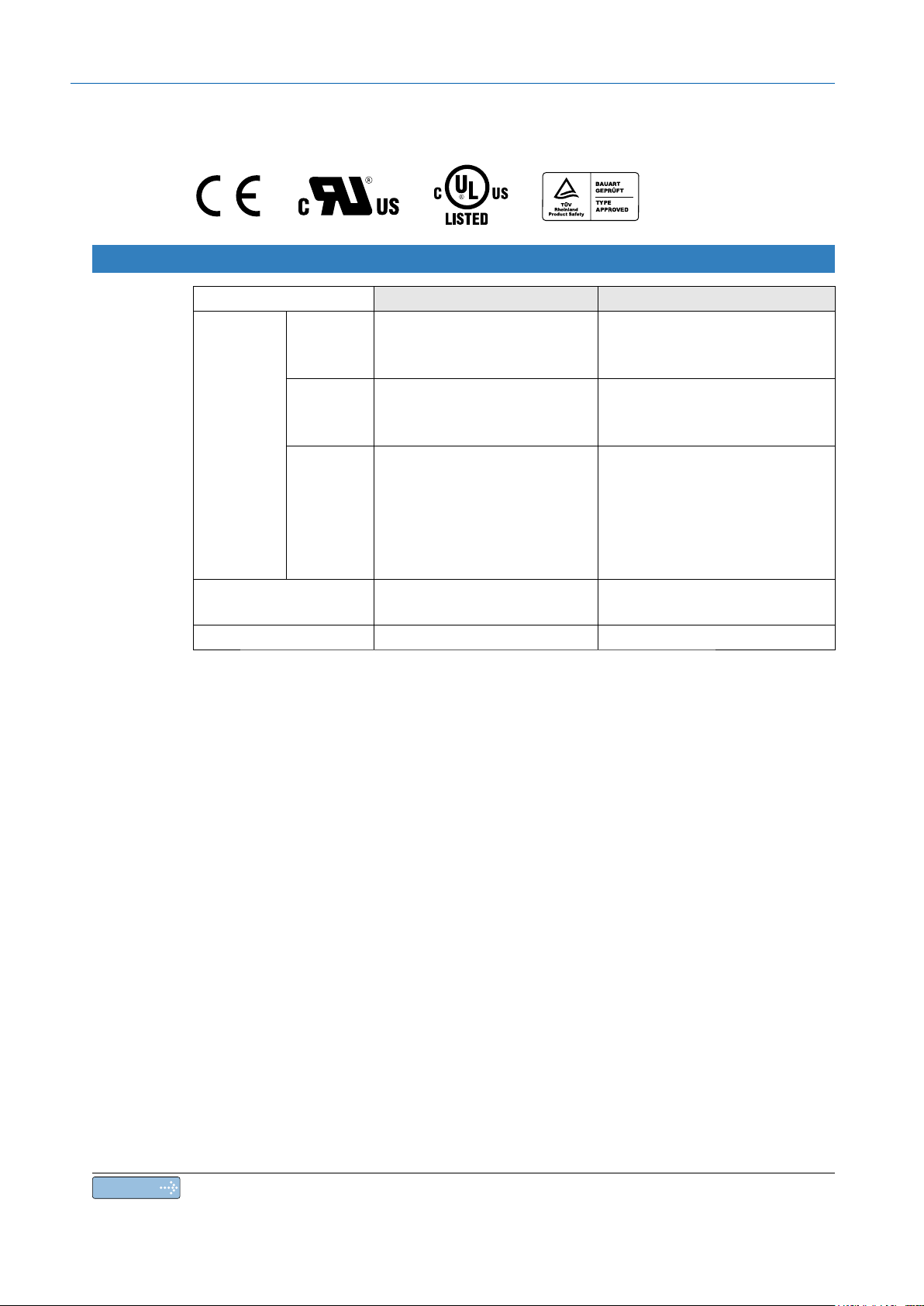
Conformance to international standards
Conformed Standards
Driver Motor
EMC
Directives
Low-
Voltage
EC Directives
UL Standards UL508C (E16
CSA Standards C22.2 No.1
Directives
Functional
safety
EN55011
EN61000-6-2
EN61800-
EN61800-5-1
EN95
ISO13849-1 (PL d)
EN61508 (SIL 2)
EN62061 (SIL 2)
EN61800-5-2 (STO)
IEC61326-3-1
3
4-1 (Cat. 3)
4620)
4 C22.2 No.100
–
EN600
EN60034-5
UL1004-1 (E327868: Small type)
UL1004 (E166557: Large type)
34-1
–
IEC : International Electrotechnical Commission
EN : Europaischen Normen
: Electromagnetic Compatibility
EMC
UL : Underwriters Laboratories
CSA : Canadian Standards Association
Pursuant to the directive 200
4/108/EC, article 9(2)
Panasonic Testing Centre
Panasonic Service Europe, a division of
Panasonic Marketing Europe GmbH
Winsbergring 15, 22525 Hamburg, F.R. Germany
10
Note
For details on compatibility with international standard, refer to P.2-2 Conformance to
international standards.

Maintenance and Inspections
Routine maintenance and inspection of the driver and motor are essential for the
proper and safe operation.
1
Before Using the Products
Notes on Maintenance and Inspection
1) Turn on and turn off should be done by operators or inspectors themselves.
2) Internal circuit of the driver is kept charged with high voltage for a while even after
power-off. Turn off the power and allow 15 minutes or longer after LED display of the
front panel has gone off, before performing maintenance and inspection.
) Disconnect all of the connection to the driver when performing megger test (Insulation
3
resistance measurement) to the driver, otherwise it could result in breakdown of the
driver.
Do not use benzine, thinner, alcohol, acidic cleaner and alkaline cleaner because they can
)
4
discolor or damage the exterior case.
Inspection Items and Cycles
General and normal running condition
Ambient conditions : 30˚C (annual average), load factor of 80% or
lower, operating hours of 20 hours or less per day.
Perform the daily and periodical inspection as per the items below.
Type Cycles Items to be inspected
2
Preparation
3
Connection
4
Setup
Daily
inspection
Motor
with Gear
Reducer
Daily
Annual
• Ambient temperature, humidity, speck, dust or foreign object
• Abnormal vibration and noise
• Main circuit voltage
• Odor
• Lint or other particles at air holes
• Cleanness at front portion of the driver and connector
• Damage of the cables
• Loose connection or misalignment between the motor and
machine or equipment
• Pinching of foreign object at the load
• Loose tightening
• Trace of overheat
• Damage to the terminal block
• Loose fasteners on terminal block
5
Adjustment
6
When in Trouble
7
Supplement
Note
Inspection cycle may change when the running conditions of the above change.
11
Maintenance and Inspections
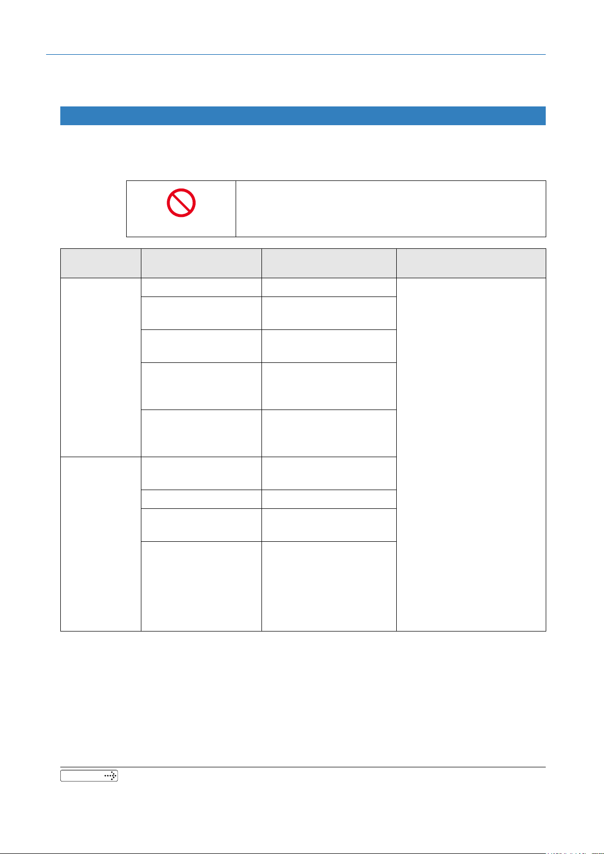
Guideline for Parts Replacement
Use the table below for a reference. Parts replacement cycle varies depending on the actual operating conditions. Defective parts should be replaced or repaired when any error
have occurred.
Disassembling for inspection and repair should be
carried out only by authorized dealers or service
Prohibited
company.
Product Component
Smoothing condenser Approx. 5 years
Cooling fan
Aluminum electrolytic
capacitor (on PCB)
Driver
Rush current
preventive relay
Rush current
preventive resistor
Bearing
Oil seal 5000 hours
Encoder
Motor
Battery
for absolute encoder
Standard replacement
cycles (hour)
3 years
2 to
(10,000 to 30,000 hours)
Approx. 5 years
Approx. 100,000 times
(depending on working
condition)
Approx. 20,000 times
(depending on working
condition)
3
to 5 years
(20,000 to 30,000 hours)
3
to 5 years
(20,000 to 30,000 hours)
Life time varies depending
on working conditions.
Refer to the Operating
Instructions attached to the
battery for absolute
encoder.
Note
These hours or cycles are
reference.
When you experience any
error, replacement is required
even before this standard
replacement cycle.
Related page
12
• P.7-96 “Warranty”

1. Before Using the Products
1. Introduction
Outline .........................................................................................................1-2
On Opening the Product Package ...............................................................1-2
2. Driver
Check of the Model ......................................................................................1-3
Parts Description (A to E-frame) ..................................................................1-
Parts Description (F-frame) .........................................................................1-5
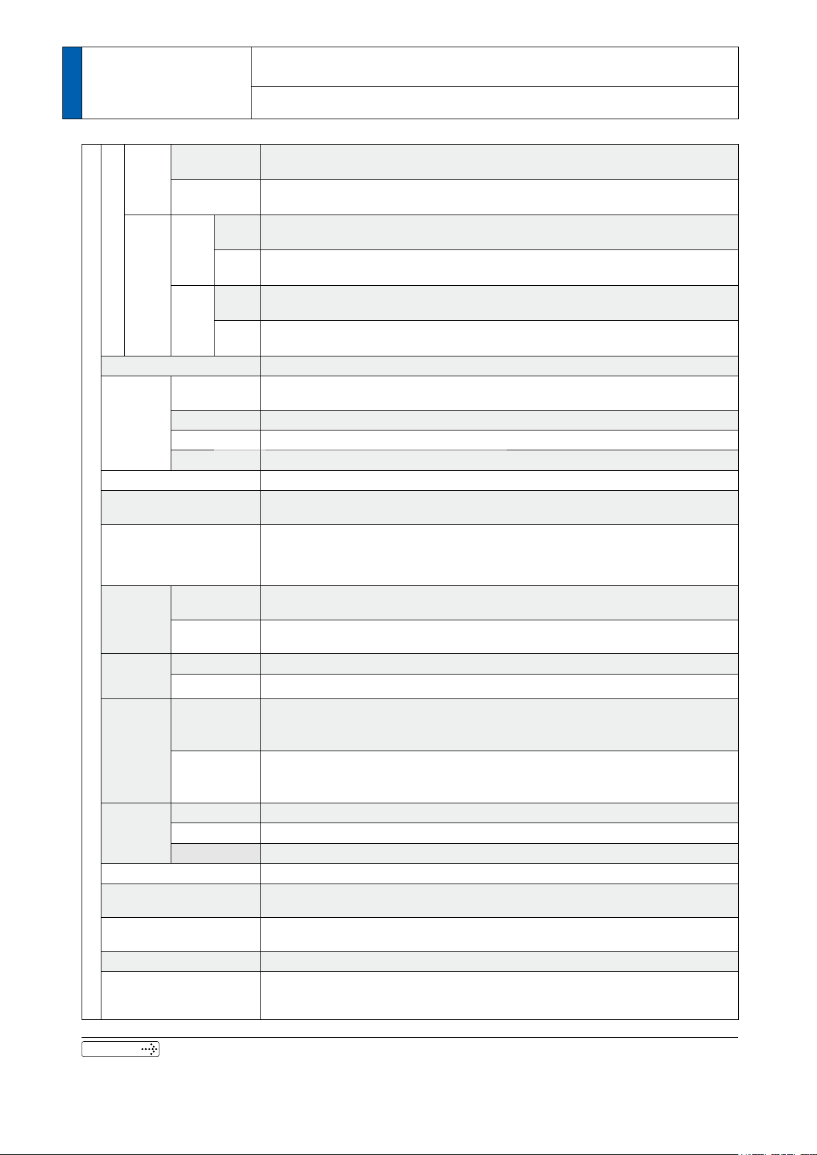
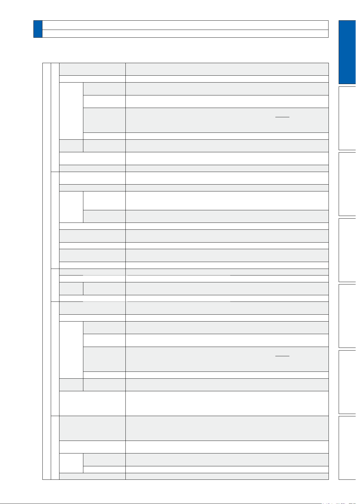
Specifications...............................................................................................1-6
Block Diagram .............................................................................................1-8
3. Motor
Check of the Model ....................................................................................1-10
Parts Description .......................................................................................1-12
4. Check of the Combination of the Driver and the Motor
Incremental Specifications, 20-bit ..............................................................1-13
Absolute Specifications, 17-bit...................................................................1-1
Junction cable for motor ...........................................................................1-15
5. Installation
Driver .........................................................................................................1-16
Motor..........................................................................................................1-20
4
4
1
Before Using the Products
2
Preparation
3
Connection
4
Setup
6. Permissible Load at Output Shaft
Motor..........................................................................................................1-23
5
Adjustment
6
When in Trouble
7
Supplement
1-1

1 Before Using
1. Introduction
the Products
The AC Servo Motor & Driver, MINAS A5-series is the latest servo system that meets all
demands from a variety of machines which require high speed, high precision and high
performance or which require simplied settings.
ompared with the preceding A4-series, product of A5-series offers superior performance
C
while requiring simple setup and adjustment by the user.
Newly designed motors have wide range of outputs from 50 W to 5.0 kW, associated with
20-bit incremental encoder and reduced cogging torque.
They are compatible with 2 closed controls (serial communication type and A-/B-phase
output type) and provided with various automatic adjusting functions such as real time
auto tuning with many automatic setting parameters to make complex tuning easy.
These motors assure higher stability with low stiffness machine and high-speed, high
accurate operation with high stiffness machine. They can be used in combination with a
wide variety of machines.
This manual is written as a complete guide for you so that you can fully and correctly
make use of all functions available from MINAS A5.
Outline
1 Before Using
the Products
• Make sure that the model is what you have ordered.
• Check if the product is damaged or not during transportation.
• Check if the Operating Instructions (safety) are included or not.
• Check if the power connector, motor connectors, connector for external regenerative
resistor connection (only E-frame) and safety by-pass plug are included or not.
(Neither the power connector nor motor connector are included to F-frame.)
Contact to a dealer if you nd any failures.
1. Introduction
On Opening the Product Package
1-2
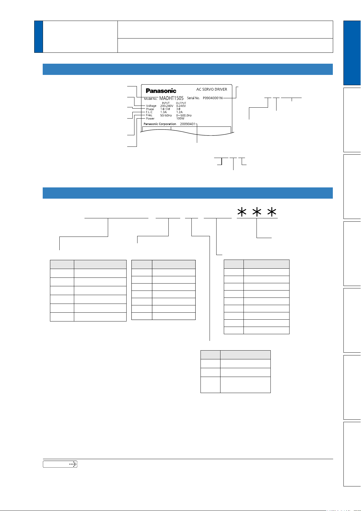
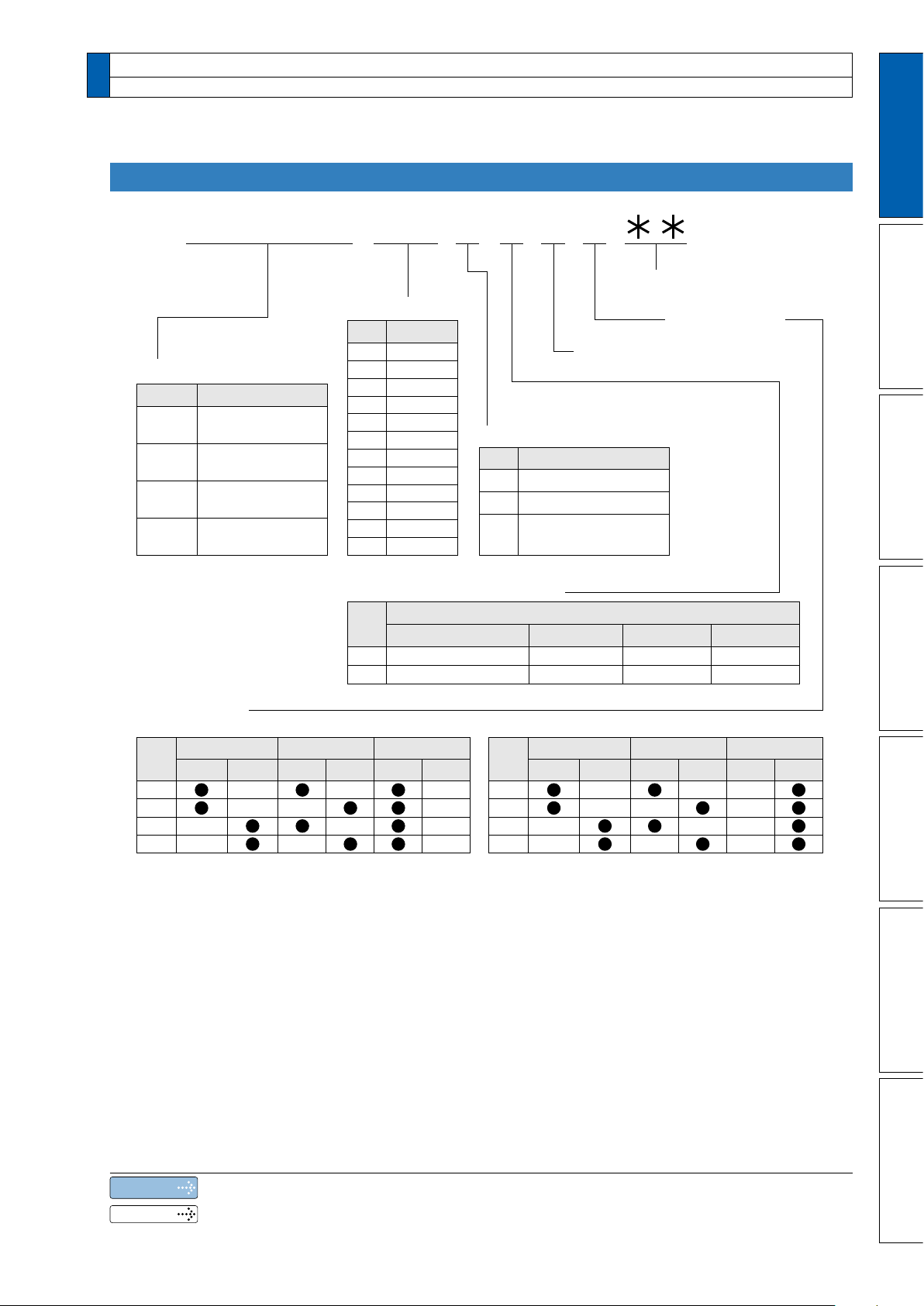
1 Before Using
Model number
Input/output voltage
Rated output of
applicable motor
Rated input/output current
Input/output frequency
Number of phase
Serial Number
e.g.) : P09040001N
Lot number
Month of production
Year of production
(Lower 2 digits of AD year)
Manufacture date
e.g.) : 20090401
Manufacture dateManufacture year
Manufacture month
M A D H T 1 5 0 5
Special specifications
(letters and numbers)
Current detector rating
Power supply
Max. current rating
of power device
Frame-size symbol
MADH
MBDH
MCDH
MDDH
MEDH
MFDH
Frame
Symbol
A5-series, A-frame
A5-series, B-frame
A5-series, C-frame
A5-series, D-frame
A5-series, E-frame
A5-series, F-frame
T1
T2
T3
T5
T7
TA
TB
Current rating
Symbol
Specifications
10A
15A
30A
50A
70A
100A
150A
Symbol
1
3
5
Single phase, 100V
3-phase, 200V
Single/3-phase,
200V
05
07
10
20
30
40
64
90
A2
Current rating
Symbol
5A
7.5A
10A
20A
30A
40A
64A
90A
120A
1 to 4 75 to 6 10 to 128 to 9
2. Driver
1
Before Using the Products
the Products
Check of the Model
Contents of Name Plate
Model Designation
2
Preparation
3
Connection
Related page
• P.1-14 “Check of the Combination of the Driver and the Motor”
1-3
4
Setup
5
Adjustment
6
When in Trouble
7
Supplement
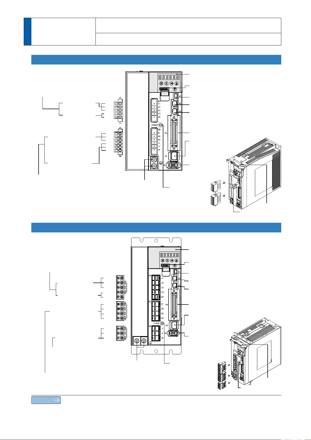
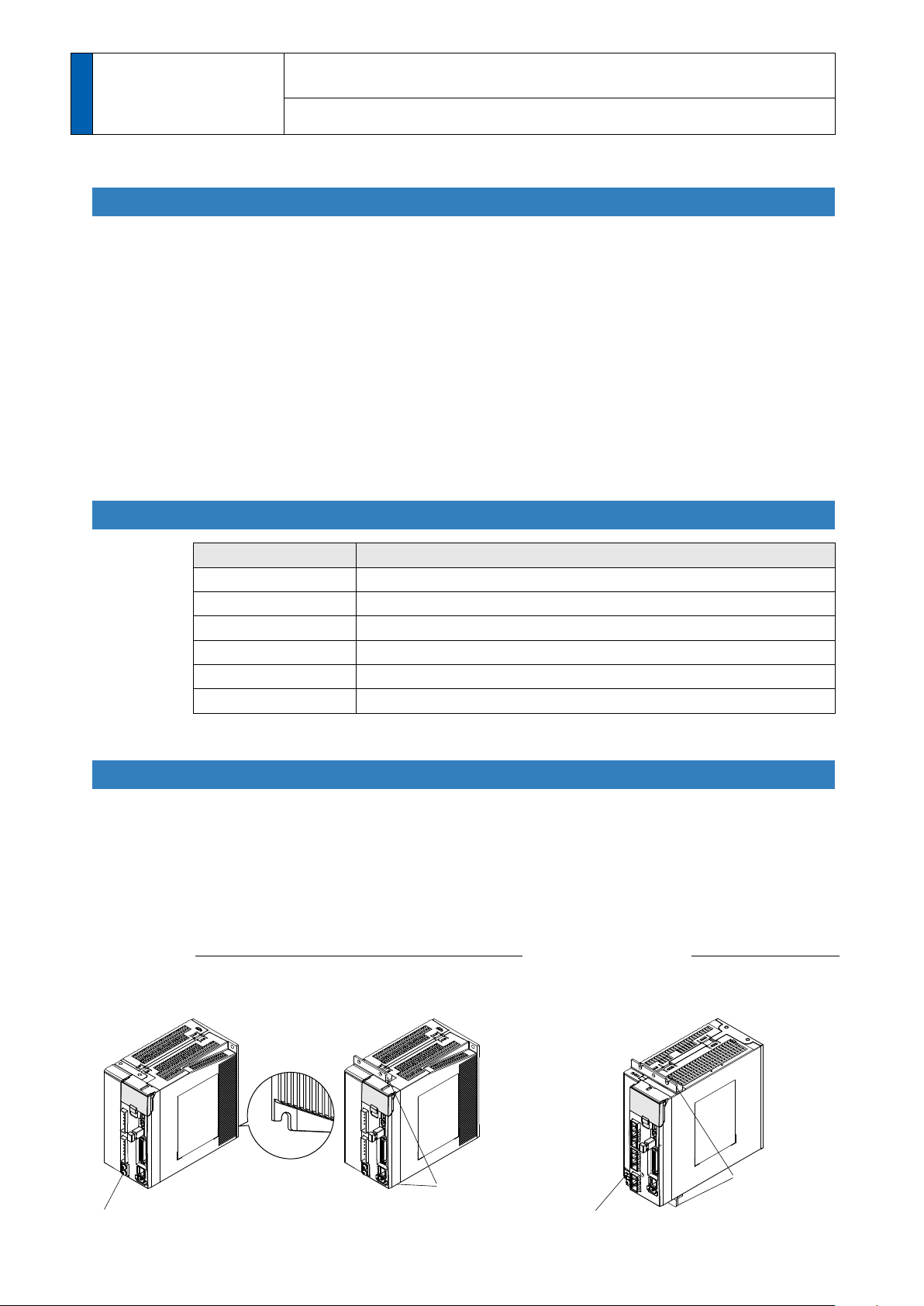
Charge lamp
L1C
L2C
L1
L2
L3
B1
B3
B2
V
U
W
Connector XA:
for main power connection
05JFAT-SAXGF (JST)
Connector XB:
for motor connection
06JFAT-SAXGF (JST)
Terminals for external
regenerative resistor
(Normally short-circuit
B3 to B2)
Connector X6:
for encoder
connection
Connector X4: Parallel I/O connector
Connector X3: Safety function connector
Connector X2: for Serial bus
Connector X1: USB connector
Connector X5:
for feedback scale
connection
Connector X7: Monitor connector
Front panel
LED cover
Safety by-pass prug
Screws for earth (x2)
Main power
input terminals
Control power
input terminals
Terminals for motor
connection
1 Before Using
Screws for earth
(x2)
Charge lamp
L1C
L2C
L1
L2
L3
B1
B3
B2
NC
U
V
W
Connector XA:
for main power connection
05JFAT-SAXGSA-L (JST)
Connector XB:
Connector for external
regenerative resistor
03JFAT-SAXGSA-L (JST)
Connector XC:
for motor connection
04JFAT-SAXGSA-L (JST)
Terminals for external
regenerative resistor
(Normally short-circuit
B3 to B2)
Terminals for motor
connection
Control power
input terminals
Main power
input terminals
Connector X6:
for encoder
connection
Connector X4: Parallel I/O connector
Connector X3: Safety function connector
Connector X2: for Serial bus
Connector X1: USB connector
Connector X5:
for feedback scale
connection
Connector X7: Monitor connector
Front panel
LED cover
Safety by-pass prug
2. Driver
the Products
A to D-frame
Parts Description
F-frame
Note
1-4
Connector X1 and X2 are attached in A to D-frame driver.
Connector XA, XB and XC are attached in E-frame driver.
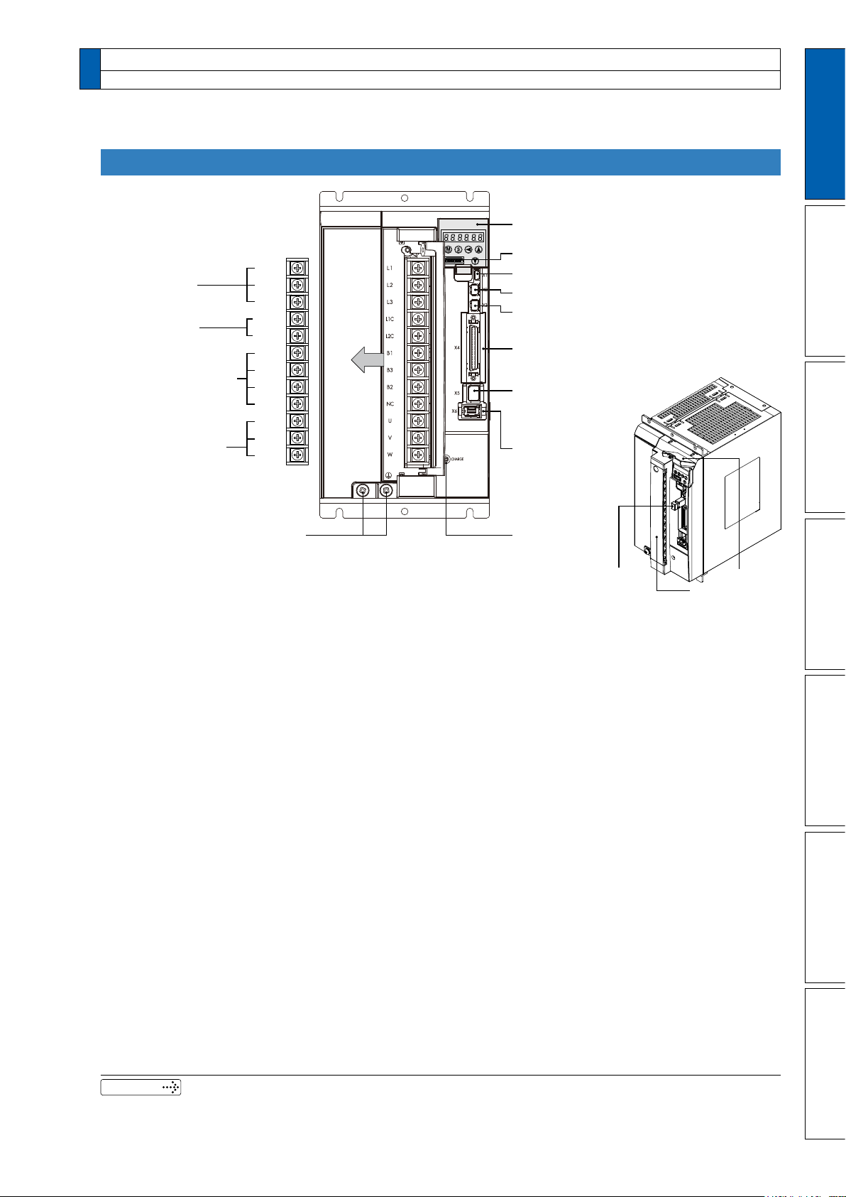
2. Driver
Control power
input terminals
L1
L2
L3
L1C
L2C
B1
B3
B2
NC
U
V
W
Main power
input terminals
Terminals for motor
connection
Screws for earth (x2)
Terminals for external
regenerative resistor
(Normally short-circuit
B3 to B2)
Charge lamp
Terminal cover
LED cover
Connector X6:
for encoder
connection
Connector X4: Parallel I/O connector
Connector X3: Safety function connector
Connector X2: for Serial bus
Connector X1: USB connector
Connector X5:
for feedback scale
connection
Connector X7: Monitor connector
Front panel
Safety by-pass prug
Parts Description
E-frame
1
Before Using the Products
2
Preparation
3
Connection
Related page
• P.1-14 “Check of the Combination of the Driver and the Motor”
• P.1-16 “Installation”
• P.2-6 “Driver and List of Applicable Peripheral Equipments”
4
Setup
5
Adjustment
6
When in Trouble
7
Supplement
1-5
1 Before Using
2. Driver
the Products
Main circuit
100V
Control circuit
Input power
D-frame
Main
circuit
200V
Control
Withstand voltage Primary to earth: withstand 1500 VAC, 1 min,(sensed current: 20 mA)
Environment
Control method IGBT PWM Sinusoidal wave drive
Encoder feedback
Basic Specications
Feedback scale feedback
Control
signal
Analog
/Digital
signal
Pulse
signal
Communication
function
Safety function Used for IEC61800-5-2: STO.
Front panel
Regeneration
Dynamic brake Built-in
Control mode
F-frame
D-frame
circuit
F-frame
temperature
humidity Both operating and storage : 20 to 85%RH or less (free from condensation)
Altitude Lower than 1000m
Vibration 5.88m/s
Input
Output
Input 3 inputs (16Bit A/D : 1 input, 12Bit A/D : 2 inputs)
Output 3 outputs (Analog monitor: 2 output, Digital monitor: 1 output)
Input
Output
USB Connection with PC etc.
RS232 1 : 1 communication to a host.
RS485 1 : n communication up to 31 axes to a host.
Specifications
Single phase, 100 to 120V
Single phase, 100 to 120V
A to
Single/3-phase, 200 to 240V
E to
3-phase, 200 to 230V
A to
Single phase, 200 to 240V
E to
Single phase, 200 to 230V
Ambient temperature: 0˚C to 55˚C (free from freezing)
Storage temperature: –20˚C to 65˚C (Max.temperature guarantee: 80˚C for 72 hours)
2
or less, 10 to 60Hz (No continuous use at resonance frequency)
17-bit (131072 resolution) absolute encoder, 7-wire serial
20-bit (1048576 resolution) incremental encoder, 5-wire serial
A/B phase, initialization signal defferential input.
Manufacturers that support serial communication scale:
Mitsutoyo Corp.
Sony Manufacturing Systems Corp.
General purpose 10 inputs
The function of general-purpose input is selected by parameters.
General purpose 6 outputs
The function of general-purpose input is selected by parameters.
2 inputs (Photo-coupler input, Line receiver input)
Photocoupler input is compatible with both line driver I/F and open collector I/F.
Line receiver input is compatible with line driver I/F.
4 outputs ( Line driver: 3 output, open collector: 1 output)
Feed out the encoder pulse (A, B and Z-phase) or feedback scale pulse (EXA, EXB and
EXZ-phase) in line driver. Z-phase and EXZ-phase pulse is also fed out in open collector.
(1) 5 keys (MODE, SET, UP, DOWN, SHIFT) (2) LED (6-digit)
(3) Analog monitor output (2ch) (4) Digital monitor output (1ch)
A, B-frame: no built-in regenerative resistor (external resistor only)
C to F-frame: Built-in regenerative resistor (external resistor is also enabled.)
Switching among the following 7 mode is enabled,
(1) Position control (2) Velocity control (3) Toque control (4) Position/Velocity control
(5) Position/Torque control (6) Velocity/Torque control (7) Full-closed control
+10%
–15%
+10%
–15%
+10%
–15%
+10%
–15%
+10%
–15%
+10%
–15%
50/60Hz
50/60Hz
50/60Hz
50/60Hz
50/60Hz
50/60Hz
Related page
1-6
• P.1-16 “Installation of Driver”
• P.1-20 “Installation of Motor”
2. Driver
Specifications
1
Before Using the Products
Control input
Control output Positioning complete (In-position) etc.
Max. command
pulse frequency
Position control
Pulse
input
Analog
input
Instantaneous Speed
Observer
Damping Control Available
Control input
Control output Speed arrival etc.
Velocity control
Analog
input
Internal velocity command Switching the internal 8speed is enabled by command input.
Soft-start/down function
Zero-speed clamp 0-clamp of internal velocity command with speed zero clamp input is enabled.
Instantaneous Speed
Observer
Function
Velocity Control lter Available
Torque control
Control input Speed zero clamp, Torque command sign input etc.
Control output Speed arrival etc.
Analog
input
Speed limit function Speed limit value with parameter t is enabled.
Control input
Control output Full-closed positioning complete etc.
Full-closed control
Pulse
input
Analog
input
Setup range of division/
multiplication of
feedback scale
Auto tuning
Common
Division of encoder
feedback pulse
Protective
function
Traceability of alarm data The alarm data history can be referred to.
Input pulse
signal format
Electronic gear
(Division/
Multiplication of
command pulse)
Smoothing lter Primary delay lter or FIR type lter is adaptable to the command input
Torque limit
command input
Velocity
command input
Torque limit
command input
Torque command
input
Max. command
pulse frequency
Input pulse
signal format
Electronic gear
(Division/
Multiplication of
command pulse)
Smoothing lter Primary delay lter or FIR type lter is adaptable to the command input
Torque limit
command input
Hard error
Soft error Excess position deviation, command pulse division error, EEPROM error etc.
(1) Deviation counter clear (2) Command pulse inhibition
(3) Command dividing gradual increase switching (4) Damping control switching etc.
Exclusive interface for Photo-coupler: 500kpps
Exclusive interface for line driver : 4Mpps
Differential input. Selectable with parameter. ((1) Positive and Negative direction,
(2) A and B-phase, (3) Command and direction)
Process command pulse frequency × electronic gear ratio
command input. Use electronic gear ratio in the range 1/1000 to 1000 times.
Individual torque limit for both positive and negative direction is enabled.
Available
(1) Selection of internal velocity setup 1 (2) Selection of internal velocity setup 2
(3) Selection of internal velocity setup 3 (4) Speed zero clamp etc.
Speed command input can be provided by means of analog voltage.
Parameters are used for scale setting and command polarity. (6V/Rated rotational
speed Default)
Individual torque limit for both positive and negative direction is enabled.
Individual setup of acceleration and deceleration is enabled, with 0 to 10s/1000r/min.
Sigmoid acceleration/deceleration is also enabled.
Available
Speed command input can be provided by means of analog voltage.
Parameters are used for scale setting and command polarity. (3V/rated torque Default)
(1) Deviation counter clear (2) Command pulse inhibition
(3) Command dividing gradual increase switching (4) Damping control switching etc.
Exclusive interface for Photo-coupler: 500kpps
Exclusive interface for line driver : 4Mpps
Differential input. Selectable with parameter. ((1) Positive and Negative direction, (2) A
and B-phase, (3) Command and direction)
Process command pulse frequency × electronic gear ratio
command input. Use electronic gear ratio in the range 1/1000 to 1000 times.
Individual torque limit for both positive and negative direction is enabled.
1/40 to 160 times
The ratio of encoder pulse (numerator) to external scale pulse (denominator) can be set
to 1 to 2
range shown above.
The load inertia is identified in real time by the driving state of the motor operating
according to the command given by the controlling device and set up support software
“PANATERM”.
The gain is set automatically in accordance with the rigidity setting.
Set up of any value is enabled (encoder pulses count is the max.).
Over-voltage, under-voltage, over-speed, over-load,
over-heat, over-current and encoder error etc.
20
(numerator) to 1 to 220 (denominator), but should be set to a ratio within the
1 to 2
(
1 to 2
1 to 2
(
1 to 2
30
)
as positional
30
30
)
as positional
30
2
Preparation
3
Connection
4
Setup
5
Adjustment
6
When in Trouble
7
Supplement
1-7
L 1
L 2
L 3
B1
B3
N
P
+
Fuse
抵抗
Fuse
Fuse
Error
detection
Voltage
detection
Sequence control
B2
L1C
L2C
X5
Feedback scale signal
processing limit
Feedback scale unit
DC/DC
X1
X2
X6
U
V
W
M
RE
X4
+
±12V
+5V
PS for gate drive
Gate drive
PS for RE
Front panel
Alarm
signal
USB
Serial
Pulse train
command
Pusle
output
Analog
velocity
command
Control
input
Division/
mulitiplication
+
+
–
–
A/D
A/D
16-bit
Position
Speed
Velocity
Torque
Internal
External
Deviation
counter
Internal speed
command
Speed
detection
Division
processing
Position
deviation amp.
Display
operation
control
Parameter control
Protective
curcuit
EEPROM
Speed
deviation
amp.
Torque
limit
Current
control
PWM
circuit
Encoder signal
processing
limit
Control
output
X3
Safety function
L 1
L 2
L 3
B1
B3
N
P
+
Fuse
抵抗
Fuse
Error
detection
Voltage
detection
Sequence control
B2
L1C
L2C
Division
processing
Feedback scale signal
processing limit
DC/DC
X6
U
V
W
M
RE
+
±12V
+5V
PS for gate drive
Gate drive
PS for RE
Alarm
signal
Pulse train
command
Pusle
output
Analog
velocity
command
Control
input
Division/
mulitiplication
+
+
–
–
A/D
A/D
16-bit
Position
Speed
Velocity
Torque
Internal
External
Deviation
counter
Internal speed
command
Speed
detection
Position
deviation amp.
Display
operation
control
Parameter control
Protective
curcuit
EEPROM
Speed
deviation
amp.
Torque
limit
Current
control
PWM
circuit
Encoder signal
processing
limit
Control
output
Fuse
Fan
(D-frame only)
Front panel
X5
Feedback scale unit
X1
X2
X4
USB
Serial
X3
Safety function
1 Before Using
2. Driver
the Products
A, B-frame
Block Diagram
C, D-frame
1-8
L 1
L 2
L 3
B1
B3
N
P
+
Fuse
抵抗
Fuse
Error
detection
Voltage
detection
Sequence control
B2
L1C
L2C
Division
processing
DC/DC
X6
U
V
W
M
RE
+
±12V
+5V
PS for gate drive
PS for RE
Fuse
Parameter control
EEPROM
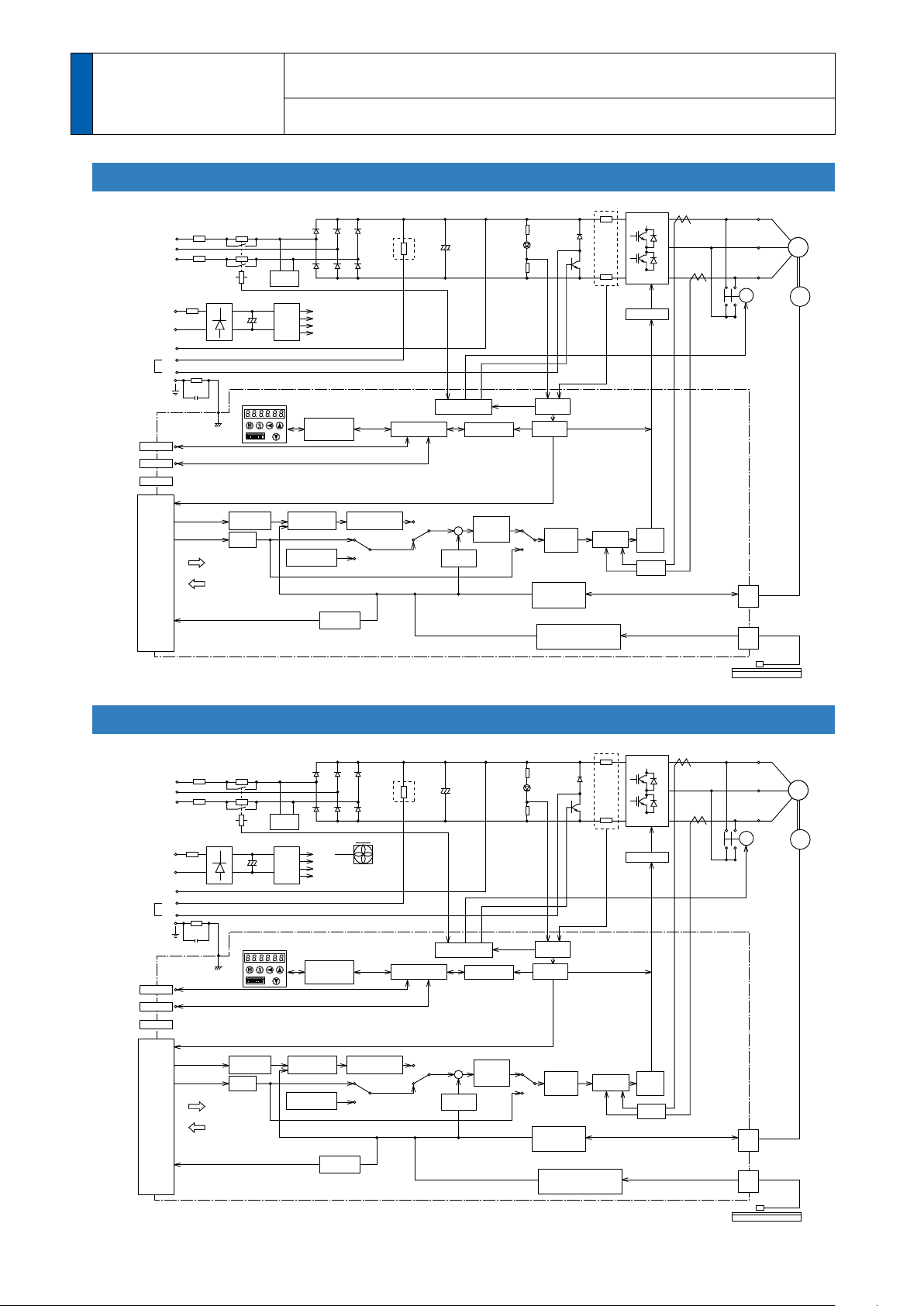
Fan
Front panel
Display
operation
control
Protective
curcuit
Alarm
signal
Pulse train
command
Pusle
output
Analog
velocity
command
Control
input
Control
output
Division/
mulitiplication
+
+
–
–
A/D
A/D
16-bit
Position
Speed
Velocity
Torque
Internal
External
Deviation
counter
Internal speed
command
Speed
detection
Position
deviation amp.
Speed
deviation
amp.
Torque
limit
Current
control
PWM
circuit
Encoder signal
processing
limit
Gate drive
X5
Feedback scale signal
processing limit
Feedback scale unit
X1
X2
X4
USB
Serial
X3
Safety function
L 1
L 2
L 3
B1
B3
N
P
+
Fuse
抵抗
Fuse
Error
detection
Voltage
detection
Sequence control
B2
L1C
L2C
Division
processing
DC/DC
X6
U
V
W
M
RE
+
±12V
+5V
PS for gate drive
PS for RE
Fuse
Parameter control
EEPROM
Fan
Front panel
Display
operation
control
Protective
curcuit
Alarm
signal
Pulse train
command
Pusle
output
Analog
velocity
command
Control
input
Control
output
Division/
mulitiplication
+
+
–
–
A/D
A/D
16-bit
Position
Speed
Velocity
Torque
Internal
External
Deviation
counter
Internal speed
command
Speed
detection
Position
deviation amp.
Speed
deviation
amp.
Torque
limit
Current
control
PWM
circuit
Encoder signal
processing
limit
Gate drive
X5
Feedback scale signal
processing limit
Feedback scale unit
X1
X2
X4
USB
Serial
X3
Safety function
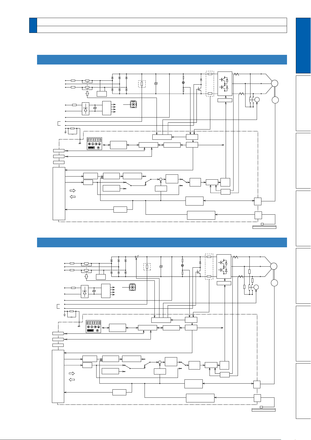
2. Driver
Block Diagram
E-frame
1
Before Using the Products
2
Preparation
3
Connection
F-frame
1-9
4
Setup
5
Adjustment
6
When in Trouble
7
Supplement

1 Before Using
Serial Number
e.g.) : 09 040001N
Lot number
Month of production
Year of production
(Lower 2 digits of AD year)
Manufacture date
e.g.) : 20090401
Manufacture dateManufacture year
Manufacture month
Model
Rated output
Rated input voltage/current
Rated frequency
Rated
rotational speed
3. Motor
the Products
Check of the Model
Contents of Name Plate
1-10
M S M E 5 A Z S 1 S
1 to 4
5 to 6
11 to 12
7
8 9 10
Special specifications
Motor structure
Design order 1: Standard
Rotary encoder specifications
Voltage specifications
Specifications
Type
Symbol
Low inertia
(50W to 5.0kW)
Middle inertia
(1.0kW to 5.0kW)
Middle inertia
(900W to 3.0kW)
High inertia
(1.0kW to 5.0kW)
G
S
Incremental
Absolute
Specifications
Symbol
Format
Pulse count
Output
Motor rated output
Symbol
Specifications
Symbol
Resolution
5-wire
7-wire
Wire count
Motor structure
MSME
(50W to 750W)
*1
The product with oil seal is a special order product.
*2 Key way with center tap
[
Products are standard stock items or manufactured by order. For details, inquire the dealer.]
A
B
S
T
Shaft
Holding brake
Oil seal
Without
With
Round
Key way
Without
With
Symbol
MSME
(1.0kW to 5.0kW)
, MDME, MGME, MHME
C
D
G
H
Shaft
Holding brake
Oil seal
Without
With
Round
Key way
Without
With
Symbol
*1
*2
*2
MSME
MDME
MGME
MHME
5A
01
02
04
08
09
10
15
20
30
40
50
50W
100W
200W
400W
750W
900W
1.0kW
1.5kW
2.0kW
3.0kW
4.0kW
5.0kW
1
2
Z
100 V
200 V
100/200 common
(50W only)
20bit
17bit
1,048,576
131,072
3. Motor
Check of the Model
Model Designation
1
Before Using the Products
2
Preparation
3
Connection
Note
Related page
For details of specic model, refer to the Dimensions of Supplement.
• P.1-14 “Check of the Combination of the Driver and the Motor”
• P.7-66 “Dimensions”
1-11
4
Setup
5
Adjustment
6
When in Trouble
7
Supplement

1 Before Using
Motor frame
Flange
Connector for motor
Connector for encoder
Connector for motor
Connector for brake
Connector for encoder
[with Brake]
Motor frame
Flange
Mounting holes (X4)
Mounting holes (X4)
Connector for motor
Connector for encoder
Oil seal
Motor frame
Flange
Mounting holes (X4)
3. Motor
the Products
• MSME 50W to 750W
Parts Description
• MSME
• MDME
• MGMA 0.9kW to
• MHME
1.0kW to 5.0kW
1.0kW to 5.0kW
1.0kW to 5.0kW
3.0kW
e.g.) : Low inertia type (MSME series, 50W)
1-12
Note
e.g.) : Middle inertia type (MDME series, 1.0kW)
For details of specic model, refer to the Dimensions of Supplement. (P.7-66)

1 Before Using
4.
Check of the Combination of the Driver and the Motor
1
Before Using the Products
the Products
This driver is designed to be used in a combination with the motor which are specied by
us. Check the series name of the motor, rated output torque, voltage specications and
encoder specications.
Remarks
Power
supply
Single
phase,
100V
Single/
-phase,
3
200V
-phase,
3
200V
Single/
-phase,
3
200V
3-phase,
200V
Single/
-phase,
3
200V
3-phase,
200V
Single/
-phase,
3
200V
3-phase,
200V
Do not use in other combinations than those listed below.
Type
MSME
Low inertia
MDME
Middle inertia
MGME
Middle inertia
MHME
High inertia
Incremental Specifications, 20-bit
Motor Driver
Rated rotational
speed
3
000r/min
2000r/min
1000r/min
2000r/min
Model
MSME5AZG1
MSME011G1
MSME021G1
MSME0
MSME5AZG1
MSME022G1
MSME0
MSME082G1
MSME102G1
MSME152G1
MSME202G1
MSME302G1
MSME502G1
MDME102G1
MDME152G1
MDME202G1
MDME302G1
MDME502G1
MGME092G1
MGME202G1
MGME
MHME102G1
MHME152G1
MHME202G1
MHME302G1
MHME502G1
41G1
42G1
402G1
402G1
302G1
402G1
*
*
*
*
*
*
*
*
*
*
*
*
*
*
*
*
*
*
*
*
*
*
*
*
*
*
*
*
*
*
Rated
output
50W MADHT1105
100W MADHT1107
200W MBDHT2110 B-frame
4
00W MCDHT3120 C-frame
50W
100W
200W MADHT1507
4
00W MBDHT2510 B-frame
750W MCDHT
1.0kW
1.5kW
2.0kW MEDHT7
3
.0kW MFDHTA390
4
.0kW
5.0kW
1.0kW MDDHT3530
1.5kW MDDHT55
2.0kW MEDHT7
3
.0kW MFDHTA390
4
.0kW
5.0kW
0.9kW MDDHT55
2.0kW MFDHT
3
.0kW MFDHTB3A2
1.0kW MDDHT3530
1.5kW MDDHT55
2.0kW MEDHT7
3
.0kW MFDHTA390
4
.0kW
5.0kW
MADHT1505
MDDHT55
MFDHTB3A2
MFDHTB3A2
MFDHTB3A2
Model Frame
A-frame
A-frameMSME012G1
3520 C-frame
40 D-frame
364 E-frame
F-frameMSME
40
364 E-frame
40 D-frame
A390
40
364 E-frame
D-frame
F-frameMDME
F-frame
D-frame
F-frameMHME
2
Preparation
3
Connection
4
Setup
5
Adjustment
6
When in Trouble
7
Note
Supplement
Sufx of " * " in the applicable motor model represents the motor structure.
1-13

1 Before Using
the Products
This driver is designed to be used in a combination with the motor which are specied by
us. Check the series name of the motor, rated output torque, voltage specications and
encoder specications.
4.
Check of the Combination of the Driver and the Motor
Absolute Specifications, 17-bit
Remarks
Power
supply
Single
phase,
100V
Single/
-phase,
3
200V
-phase,
3
200V
Single/
-phase,
3
200V
3-phase,
200V
Single/
-phase,
3
200V
3-phase,
200V
Single/
-phase,
3
200V
3-phase,
200V
Do not use in other combinations than those listed below.
Motor Driver
Type
MSME
Low inertia
MDME
Middle inertia
MGME
Middle inertia
MHME
High inertia
Rated rotational
speed
3
000r/min
2000r/min
1000r/min
2000r/min
Model
MSME5AZS1
MSME011S1
MSME021S1
MSME0
MSME5AZS1
MSME022S1
MSME0
MSME082S1
MSME102S1
MSME152S1
MSME202S1
MSME302S1
MSME502S1
MDME102S1
MDME152S1
MDME202S1
MDME302S1
MDME502S1
MGME092S1
MGME202S1
MGME
MHME102S1
MHME152S1
MHME202S1
MHME302S1
MHME502S1
41S1
42S1
402S1
402S1
302S1
402S1
*
*
*
*
*
*
*
*
*
*
*
*
*
*
*
*
*
*
*
*
*
*
*
*
*
*
*
*
*
*
Rated
output
50W MADHT1105
100W MADHT1107
200W MBDHT2110 B-frame
4
00W MCDHT3120 C-frame
50W
100W
200W MADHT1507
4
00W MBDHT2510 B-frame
750W MCDHT
1.0kW
1.5kW
2.0kW MEDHT7
3
.0kW MFDHTA390
4
.0kW
5.0kW
1.0kW MDDHT3530
1.5kW MDDHT55
2.0kW MEDHT7
3
.0kW MFDHTA390
4
.0kW
5.0kW
0.9kW MDDHT55
2.0kW MFDHT
3
.0kW MFDHTB3A2
1.0kW MDDHT3530
1.5kW MDDHT55
2.0kW MEDHT7
3
.0kW MFDHTA390
4
.0kW
5.0kW
Model Frame
MADHT1505
3520 C-frame
MDDHT55
MFDHTB3A2
MFDHTB3A2
MFDHTB3A2
40 D-frame
364 E-frame
40
364 E-frame
40 D-frame
A390
40
364 E-frame
A-frame
A-frameMSME012S1
F-frameMSME
D-frame
F-frameMDME
F-frame
D-frame
F-frameMHME
1-14
Note
1) Sufx of " * " in the applicable motor model represents the motor structure.
2) Default of the driver is set for the incremental encoder specications.
When you use in absolute, make the following operations.
a) Install a battery for absolute encoder.
b)
Switch the parameter Pr0.15 (Absolute encoder setup) from "1 (default)" to "0".
1 Before Using
4.
Check of the Combination of the Driver and the Motor
1
Before Using the Products
the Products
Junction cable for motor
Encoder cable
Motor series Incremental Specications, 20-bit
MSME 50W to 750W MFECA0**0MJD MFECA0**0MJE
MSME 1.0kW to 5.0kW MFECA0**0ETD MFECA0**0ETE
MDME 1.0kW to 5.0kW MFECA0**0ETD MFECA0**0ETE
MGME 0.9kW to 3.0kW MFECA0**0ETD MFECA0**0ETE
MHME 1.0kW to 5.0kW MFECA0**0ETD MFECA0**0ETE
Note)1 “
** ”
represents the cable length.
Note)1
Absolute Specifications, 17-bit
Motor cable/ Brake cable
Motor series
MSME 50W to 750W MFMCA0**0NJD — MFMCB0**0PJT
MSME 1.0kW to 2.0kW MFMCD0**2ECD MFMCA0**2FCD
MSME 3.0kW to 5.0kW MFMCA0**3
Motor cable
ECT MFMCA0**3FCT
Note)1
with Brake
Brake cable
—
Note)1
Note)1
Detail
page
7-76
7-77
Detail
page
7-78
7-82
2
Preparation
3
Connection
4
MDME 1.0kW to 2.0kW MFMCD0**2ECD MFMCA0**2FCD
MDME
MGME 0.9kW MFMCD0**2ECD MFMCA0**2FCD
MGME 2.0kW to
MHME 1.0kW to 1.5kW MFMCD0**2ECD MFMCA0**2FCD
MHME 3.0kW to 5.0kW
Note)1 “
3.0kW to 5.0kW MFMCA0**3
3.0kW MFMCA0**3
MFMCA0**3
** ”
represents the cable length.
ECT MFMCA0**3FCT
ECT MFMCA0**3FCT
ECD MFMCE0**3FCD
ECT MFMCA0**3FCT
—
—
—MHME 2.0kW MFMCE0**3
7-78
…
7-81
Setup
5
Adjustment
6
When in Trouble
Related page
• For other cable, connector and connector kit, refer to P.7-72 “Options”
1-15
7
Supplement
1 Before Using
A to D-frame E, F-frame
Basemount (Standard)
[Rear mount]
Frontmount
[Use mounting fixture]
Front or Basemount
[Use mounting fixture]
Mounting fixture
(optional parts)
Mounting fixture
(Attachment)
Fastening torque of earth screws (M4)
to be 0.7 to 0.8 N
•
m.
Fastening torque of earth screws (M5)
to be 1.4 to 1.6 N•m.
5. Installation
the Products
Driver
Install the driver properly to avoid a breakdown or an accident.
Installation Place
1) Install the driver in a control panel enclosed in noncombustible material and placed indoor where the product is not subjected to rain or direct sunlight. The products are not
waterproof.
Where the products are not subjected to corrosive atmospheres such as hydrogen sul-
2)
de, sulfurous acid, chlorine, ammonia, sulfur, chloric gas, sulfuric gas, acid, alkaline
and salt and so on, and are free from splash of inammable gas.
) Where the motor is free from grinding oil, oil mist, iron powder or chips.
3
4) Well-ventilated and low humidity and dust-free place.
5) Vibration-free place.
Do not use benzine, thinner, alcohol, acidic cleaner and alkaline cleaner because they can
6)
discolor or damage the exterior case.
Environmental Conditions
Item Conditions
Ambient temperature 0˚C to 55˚C (free from freezing)
Ambient humidity 20% to 85% RH (free from condensation)
*
Storage temperature
Storage humidity 20% to 85% RH (free from condensation)
Vibration Lower than 5.88m/s
Altitude Lower than 1000m
1
–20˚C to 65˚C (Max.temperature guarantee: 80˚C for 72 hours)
2
(0.6G), 10 to 60Hz
*
Extreme temperatures are permissible only for short period such as during transportation.
1
How to Install
1) Rack-mount type. Install in vertical position, and reserve enough space around the
servo driver for ventilation.
2) Base mount (rear mount) is standard for A/B/C/D-frame driver.
) To change the mounting surface of A/B/C/D-frame driver, use the optional mounting
3
xture. For choosing the correct optional mounting xture, refer to P.7-90 “Mounting
Bracket”.
1-16
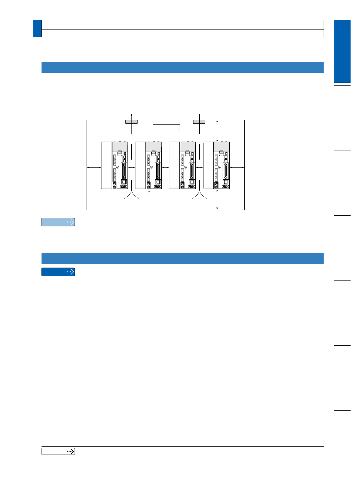
Fan Fan
100mm
or more
100mm
or more
40mm
or
more
40mm
or
more
10
mm
or
more
10
mm
or
more
10
mm
or
more
Direction of air flowing
from the internal
cooling fan (D/E/F frame)
Control panel
5. Installation
Driver
Mounting Direction and Spacing
• Reserve enough surrounding space for effective cooling.
• Install fans to provide uniform distribution of temperature in the control panel.
• D/E/F frame is provided with a cooling fan at the bottom.
Observe the environmental conditions of the control panel described in the previous page.
•
1
Before Using the Products
2
Preparation
3
Connection
Note
It is recommended to use the conductive paint when you make your own mounting xture, or repaint after peeling off the paint on the machine for installing the products, in
order to make noise countermeasure.
Caution on Installation
•
Caution
We have been making the best effort to ensure the highest quality, however, application of
exceptionally large external noise disturbance and static electricity, or failure in input power, wiring and components may result in unexpected action. It is highly recommended that
you make a fail-safe design and secure the safety in the operative range.
•
If stranded wires are used as the cable, bunch the conductors of the cable using a rod terminals or a round terminals. If stranded wires are used as they are, unexpected accidents such
as an electric shock and short circuit or injury may result.
• There might be a chance of smoke generation due to the failure of these products. Pay
an extra attention when you apply these products in a clean room environment.
Be sure to ground the protective earth terminal.
•
If the product is grounded insufciently, not only the driver may not deliver its perfor
mance sufciently, but also safety hazards such as a malfunction due to a electrication
or a disturbance may be caused.
If electric wires are bound and run through metal duct, they cannot carry the rated cur-
•
rent due to temperature rise. If they are forced to carry the rated current, they may burn.
When determining size of the wire.
4
Setup
5
Adjustment
6
-
When in Trouble
7
Related page
• P.1-6 “Specications” • P.1-20 “Installation of motor”
• P.7-63 “Dimensions” • P.7-90 “Mounting xture”
Supplement
1-17
27
37
49
61
88
115
139
2 to 3.5 (excl.)
3.5 to 5.5 (excl.)
5.5 to 8 (excl.)
8 to 14 (excl.)
14 to 22 (excl.)
11 to 30 (excl.)
30 to 38 (excl.)
Stranded
conductor
(nominal cross section: mm2)
Copper
wire
(unit: A)
•
Fundamental permissible current
5. Installation
Driver
Recommended Electric Wires for Driver
• For the main circuit, use electric wire that withstands at least 600 VAC with tempera-
ture rating 75℃ or higher.
When using bundled wires running through metallic conduit, the amounts of current
•
determined according to the reduction rate must be subtracted from the nominal allowable current.
Electric wires
•
<In high ambient temperature>
Use heat resistant wire.
Common polyvinyl chloride wires will deteriorate by heat at a higher rate.
<In low ambient temperature>
The surface of vinyl chloride insulation becomes hardened and brittle at low tempera-
ture and needs specic protective measure when used in cold region.
• Bend radius of the cable must be 10 times or more its nish outside diameter.
• Cables cannot be used for continuous regeneration because they are not designed for
such application.
Relationship between Wire Diameter and Permissible Current
• When selecting a cable, refer to the following selection guide showing relationship be-
tween cable specication and current carrying capacity.
Example: Power supply 3-phase, 200 V, 35 A, ambient temperature 30°C
Determine the fundamental permissible current according
to the cable conductor material (example: stranded copper wire).
(For the purpose of this example, the ampere indicated by
Next, determine the number of conductors.
(
ground).)
Determine the applicable permissible current using the
following formula.
Applicable permissible current
=
= 37 x 0.7 x 1.414
.=.
This permissible value is larger than 35 A to be carried though the cable. Therefore,
according to the list of recommended eco-cables, the cable to be selected for the cable
with
1-18
ductor power cable having 13.5 mm nish O.D. (approx. 14.5 mm with shield).
is selected from the table right.)
In this example, the cable contains 4 conductors (3 +
fundamental permissible current x current reduction coefcient x current correction coefcient
36.6 (A)
2
nominal cross section 3.5 mm
is a polyethylene-insulated heat-resistant 4-con-
 Loading...