

Page 1
Technical referenc
e
AC Servo Motor & Drive
r
MINAS A4-series
If you are the first user of this product, please be sure to purchase and read
the optional Engineering Material (DV0P4210), or downloaded Instruction
Manual from our Web Site.
[Web address of Motor Company, Matsushita Electric Industrial Co., Ltd.]
http://industrial.panasonic.com/ww/i_e/25000/motor_fa_e/motor_fa_e.html
Thank you very much for your
purchase of Panasonic AC Servo
Motor & Driver, MINAS A4-series.
Before use, refer this technical
reference and safety instructions
to ensure proper use. Keep this
technical reference and read
when necessary.
Make sure to forward this technical
reference for safety to the final
user.
•
•
•
IMC54D
Z0404-6066
1. Introduction................................. B2
On Opening the Package ............................... B2
Check of the Driver Model .............................. B2
Check of the Motor Model .............................. B3
2. Installation .................................. B4
Driver .............................................................. B4
Motor .............................................................. B6
Console .......................................................... B8
3. System Configuration and
Wiring ........................................B10
Overall Wiring
(Connecting Example of C-frame, 3-
phase) ..............................................................
B10
Overall Wiring
(Connecting Example of E-frame) ....
B12
Driver and List of Applicable Peripheral
Equipments .................................................. B14
Wiring of the Main Circuit (A to D-frame) ..... B16
Wiring of the Main Circuit (E and F-frame) ... B17
Wiring method to connector (A to D-frame).. B18
Wiring to the Connector, CN X6
(Connection to Encoder) .............................. B22
Wiring for Typical Control Modes
to the Connector CN X5 ............................... B24
4. Parameter.................................. B27
Outline of Parameter .................................... B27
How to Set .................................................... B27
Setup with the Front Panel ........................... B27
Outline of PANATERM
®
.......................................................
B28
Setup with the Console ................................ B28
How to Connect ............................................ B29
Composition and List of Parameters ............ B30
5. Protective Functions................ B36
Protective Function (What Is Error Code ?) .....
B36
6. Maintenance and Inspections . B38
7. Conformity to EC Directives
and UL Standards ..................... B40
Composition of Peripheral Equipments ........ B41
Conformity to UL Standards ......................... B44
8. Built-in Holding Brake ............. B45
9. Dynamic Brake ......................... B47
10.
Check of the Combination of
the Driver and the Motor ............
B48
After-Sale Service (Repair) .......... B51
page page
<Contents>
Page 2
R
ated input voltage/current
r)
Check of the Motor Model
Contents of Name Plate
Model Designation
s
s)
MAMA
MQMA
MSMD
MSMA
MDMA
MHMA
MFMA
MGMA
Symbol
Motor structure
MSMD, MQMA MAMA
*
1 The product with oil seal is a special order
product.
*
2 Key way with center tap
A
B
S
T
Symbol
Products are standard stock items or build to
order items. For details, inquire of the dealer.
1. Introduction
On Opening the Product Package
• Make sure that the model is what you have ordered.
• Check if the product is damaged or not during transportation.
• Check if the instruction manual is attached or not.
• Check if the power connector and motor connecters (CN X1 and CN X2 connectors)
are attached or not (A to D-frame).
Contact to a dealer if you find any failures.
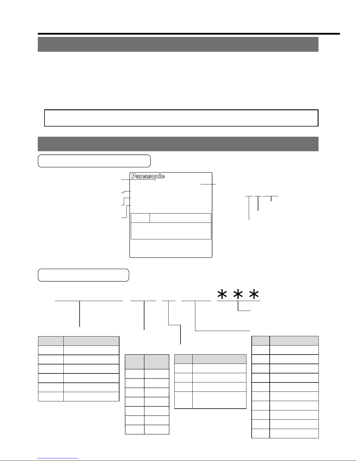
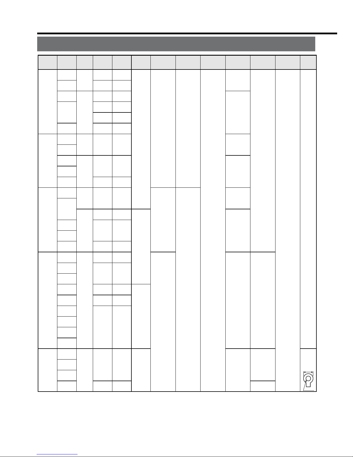
Check of the Driver Model
Contents of Name Plate
Model Designation
M A D D T 1 2 0 5
Special specification
s
(letters and numbers
)
Current detector ratin
g
Power supply
Max. current
rating of
power device
F
rame-size symbol
MADD
MBDD
MCDD
MDDD
MEDD
MFDD
Frame
Symbol
A4-series, A-frame
A4-series, B-frame
A4-series, C-frame
A4-series, D-frame
A4-series, E-frame
A4-series, F-frame
T1
T2
T3
T5
T7
TA
TB
Current
rating
Symbol
Specifications
10A
15A
30A
50A
70A
100A
150A
Symbol
1
2
3
5
Single phase, 100V
Single phase, 200V
3-phase, 200V
Single/3-phase,
200V
05
07
10
15
20
30
40
64
90
A2
Current rating
Symbol
5A
7.5A
10A
15A
20A
30A
40A
64A
90A
120A
1 to 4 75 to 6 10 to 128 to 9
Model number
R
ated input/output voltage
Rated output of
applicable motor
Rated input/output current
Serial Number
MADDT1205
e.g.) :
P04 11 0001Z
Lot number
Month of productio
n
Year of production
(Lower 2 digits of AD yea
r)
50/60Hz
100W
1.3A
1ø
200-240V
Freq.
Model No.
AC SERVO
Serial No.P04110001Z
INPUT
Voltage
Phase
F.L.C
Power
OUTPUT
69V
3ø
1.2A
0~333.3Hz
Page 3
– B3 –– B2 –
AC SERVO MOTOR
RATING S1
MODEL No.
MSMD5AZS1S
INS. CLASS B (TÜV) A (UL)
CONT. TORQUE
0.64
Nm
A1.6
CONNECTION
RATED OUTPUT
RATED FREQ.
kW
0.2
SER No.
04110001
Hz
200
RATED REV.
r/min
3000
INPUT 3ØAC
92
IP65
V
Model
Rated output
R
ated input voltage/current
Rated rotational speed
Serial Number
e.g.) :
0411 0001
Lot number
Month of production
Year of production
(Lower 2 digits of AD yea
r)
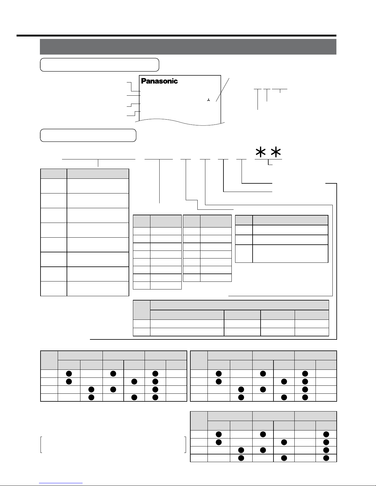
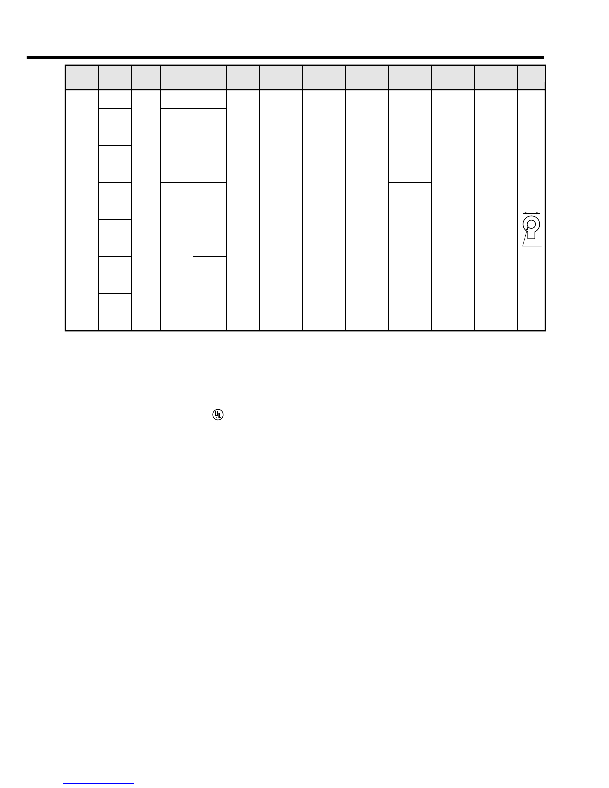
Check of the Motor Model
Contents of Name Plate
Model Designation
M S M D 5 A Z S 1 S
1 to 4
5 to 6
11 to 12
7
8 9 10
Special specification
s
(letters and number
s)
Motor structure
Design order
1: Standard
Rotary encoder specifications
Voltage specifications
MAMA
MQMA
MSMD
MSMA
MDMA
MHMA
MFMA
MGMA
Type
Symbol
Ultra low inertia
(100W to 750W)
Low inertia
(100W to 400W)
Low inertia
(50W to 750W)
Low inertia
(1.0kW to 5.0kW)
Middle inertia
(1.0kW to 5.0kW)
High inertia
(500W to 5.0kW)
Middle inertia
(400W to 4.5kW)
Middle inertia
(900W to 4.5kW)
P
S
Incremental
Absolute/Incremental common
Specifications
Symbol
Format
2500P/r
17bit
Pulse count
5A
01
02
04
05
08
09
10
Output
Motor rated output
Symbol
50W
100W
200W
400W
500W
750W
900W
1.0kW
15
20
25
30
40
45
50
Output
Symbol
1.5kW
2.0kW
2.5kW
3.0kW
4.0kW
4.5kW
5.0kW
1
2
Z
Specifications
Symbol
100 V
200 V
100/200 common
(50W only)
10,000
131,072
Resolution
5-wire
7-wire
Wire count
Motor structure
MSMD, MQMA MAMA
*
1 The product with oil seal is a special order
product.
*
2 Key way with center tap
A
B
E
F
Shaft
Holding brake
Oil seal
Without
With
Round
Key way
Without
With
Symbol
A
B
S
T
Shaft
Holding brake
Oil seal
Without
With
Round
Key way
Without
With
Symbol
MSMA, MDMA, MFMA, MGMA, MHMA
C
D
G
H
Shaft
Holding brake
Oil seal
Without
With
Round
Key way
Without
With
Symbol
*
1
*
2
*
2
Products are standard stock items or build to
order items. For details, inquire of the dealer.
Page 4
Install the driver and the motor properly to avoid a breakdown or an accident.
Driver
Installation Place
1) Indoors, where the products are not subjected to rain or direct sun beams. The products are not waterproof.
2) Where the products are not subjected to corrosive atmospheres such as hydrogen
sulfide, sulfurous acid, chlorine, ammonia, chloric gas, sulfuric gas, acid, alkaline and
salt and so on, and are free from splash of inflammable gas, grinding oil, oil mist, iron
powder or chips and etc.
3) Well-ventilated and low humidity and dust-free place.
4) Vibration-free place.
Environmental Conditions
Ambient temperature
Ambient humidity
Storage temperature
Storage humidity
Vibration
Altitude
ConditionsItem
0˚C to 55˚C (free from freezing)
Less than 90% RH (free from condensation)
–20˚C to 80˚C (free from freezing)
Less than 90% RH (free from condensation)
Lower than 5.9m/s
2
(0.6G), 10 to 60Hz
Lower than 1000m
Fan Fan
100mm
or more
100mm
or more
40mm
or
more
40mm
or
more
10mm
or
more
10mm
or
more
10mm
or
more
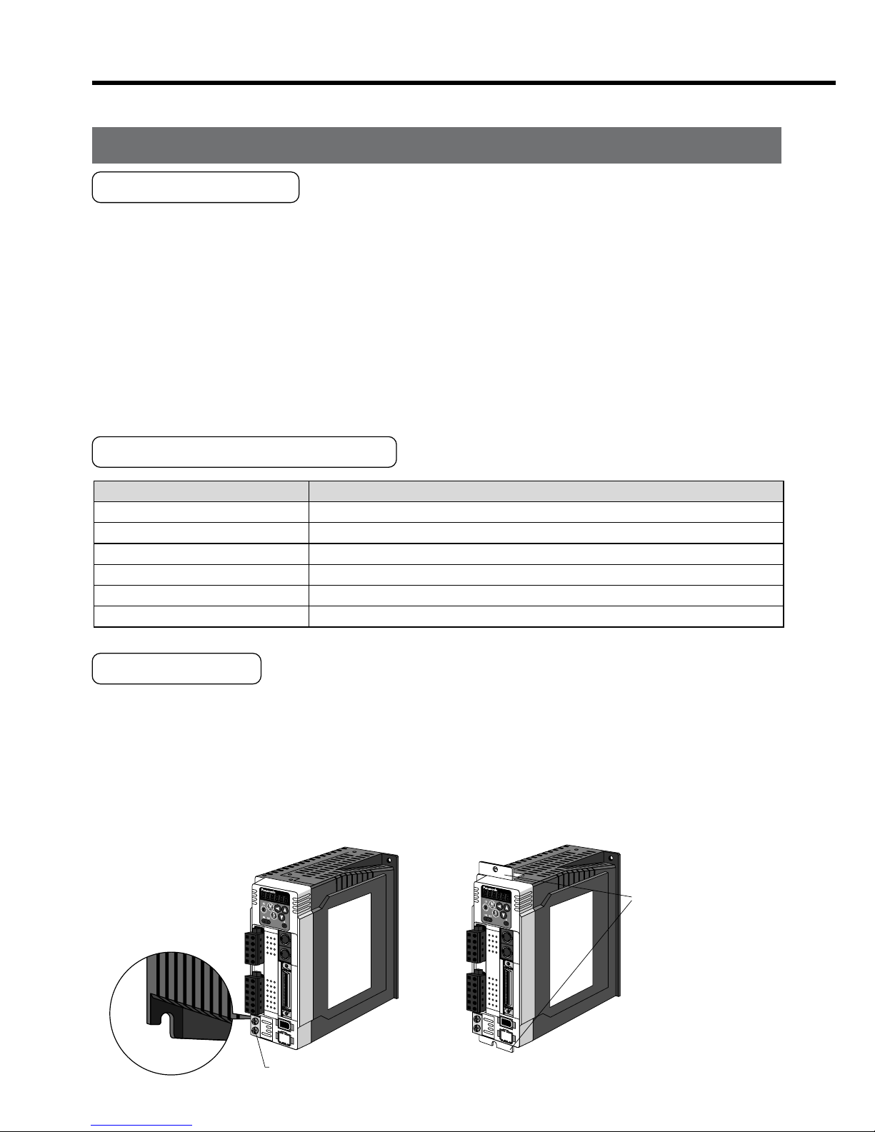
A
to D-frame e.g.) In case of C-frame
Fastening torque of earth screws (M4) to be 0.39 to 0.59N
•
m.
Mounting brack
et
(optional parts)
MADD
MBDD
MCDD
MDDD
E
et
2. Installation
How to Install
1) Rack-mount type. Install in vertical position, and reserve enough space around the
servo driver for ventilation.
Base mount type (rear mount) is standard (A to D-frame)
2) Use the optional mounting bracket when you want to change the mounting face.
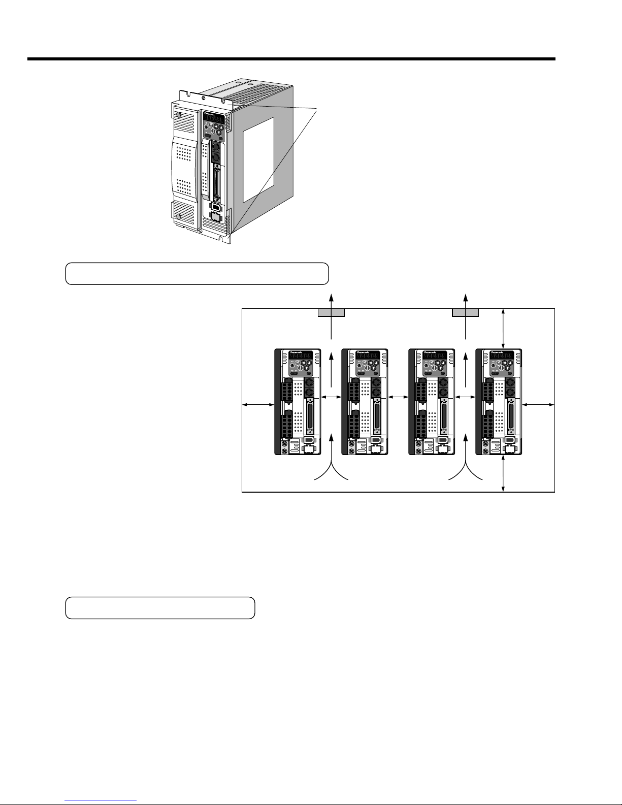
Mounting Direction and Spacing
• Reserve enough surround-
ing space for effective cool-
ing.
• Install fans to provide uni-
form distribution of tem-
perature in the control
panel.
• Observe the environmental
conditions of the control
panel described in the next
page.
<Note>
It is recommended to use the conductive paint when you make your own mounting
bracket, or repaint after peeling off the paint on the machine for installing the products, in
order to make noise countermeasure.
Caution on Installation
We have been making the best effort to ensure the highest quality, however, application
of exceptionally large external noise disturbance and static electricity, or failure in input
power, wiring and components may result in unexpected action. It is highly recommended
that you make a fail-safe design and secure the safety in the operative range.
There might be a chance of smoke generation due to the failure of these products. Pay
an extra attention when you apply these products in a clean room environment.
Page 5
– B5 –– B4 –
Fan Fan
100mm
or more
100mm
or more
40mm
or
more
40mm
or
more
10mm
or
more
10mm
or
more
10mm
or
more
E
and F-frame
Mounting brack
et
Mounting Direction and Spacing
• Reserve enough surrounding space for effective cooling.
• Install fans to provide uniform distribution of temperature in the control
panel.
• Observe the environmental
conditions of the control
panel described in the next
page.
<Note>
It is recommended to use the conductive paint when you make your own mounting
bracket, or repaint after peeling off the paint on the machine for installing the products, in
order to make noise countermeasure.
Caution on Installation
We have been making the best effort to ensure the highest quality, however, application
of exceptionally large external noise disturbance and static electricity, or failure in input
power, wiring and components may result in unexpected action. It is highly recommended
that you make a fail-safe design and secure the safety in the operative range.
There might be a chance of smoke generation due to the failure of these products. Pay
an extra attention when you apply these products in a clean room environment.
Page 6

Ambient temperature
Ambient humidity
Storage temperature
Storage humidity
Vibration
Impact
Enclosure
rating
ConditionItem
0˚C to 40˚C (free from freezing)
*1
Less than 85% RH (free from condensation)
–20˚C to 80˚C (free from freezing)
*2
Less than 85% RH (free from condensation)
Lower than 49m/s
2
(5G) at running, 24.5m/s2 (2.5G) at stall
Lower than 98m/s
2
(10G)
IP65 (except rotating portion of output shaft and lead wire end)
These motors conform to the test conditions specified in EN standard
s
(EN60529, EN60034-5). Do not use these motors in application wher
e
water proof performance is required such as continuous wash-dow
n
operation.
Motor only
Motor only
Motor only
•
2. Installation
Motor
Installation Place
Since the conditions of location affect a lot to the motor life, select a place which meets
the conditions below.
1) Indoors, where the products are not subjected to rain or direct sun beam. The products are not waterproof.
2) Where the products are not subjected to corrosive atmospheres such as hydrogen
sulfide, sulfurous acid, chlorine, ammonia, chloric gas, sulfuric gas, acid, alkaline and
salt and so on, and are free from splash of inflammable gas, grinding oil, oil mist, iron
powder or chips and etc.
3) Where the motor is free from grinding oil, oil mist, iron powder or chips.
4) Well-ventilated and humid and dust-free place, far apart from the heat source such as
a furnace.
5) Easy-to-access place for inspection and cleaning
6) Vibration-free place.
7) Avoid enclosed place. Motor may gets hot in those enclosure and shorten the motor life.
Environmental Conditions
*1 Ambient temperature to be measured at 5cm away from the motor.
*2 Permissible temperature for short duration such as transportation.
How to Install
You can mount the motor either horizontally or vertically as long as you observe the followings.
1) Horizontal mounting
• Mount the motor with cable outlet facing downward for water/oil countermeasure.
2) Vertical mounting
• Use the motor with oil seal (non-standard) when mounting the motor with gear
reducer to prevent the reducer oil/grease from entering to the motor.
3) For mounting dimensions, refer to the technical reference. (DV0P4210)
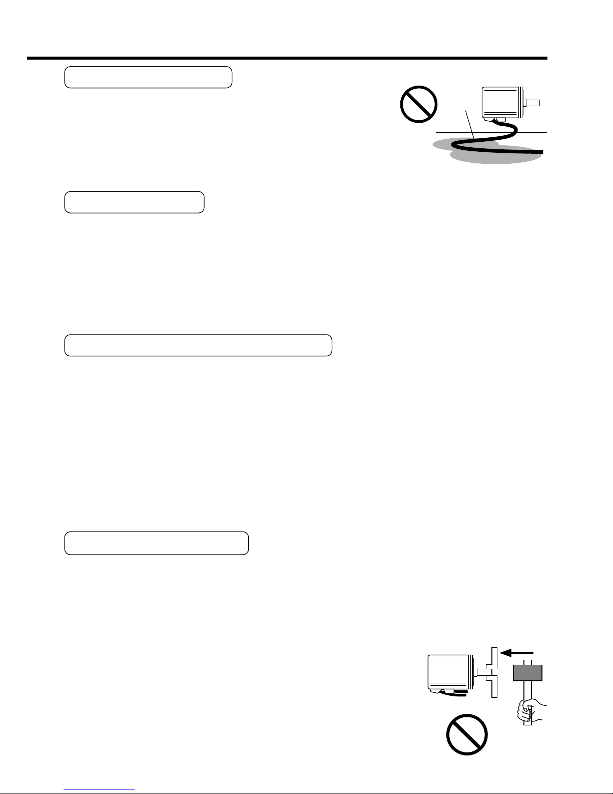
Oil/Water Protection
1) Don't submerge the motor cable to water or oil.
2) Install the motor with the cable outlet facing downward.
3) Avoid a place where the motor is subjected to oil or water.
4) Use the motor with an oil seal when used with the gear re-
ducer, so that the oil may not enter to the motor through shaft.
Stress to Cables
1) Avoid a stress application to the cable outlet and connecting portion by bending or
self-weight.
2) Especially in an application where the motor itself travels, fix the attached cable and
contain the extension junction cable into the bearer so that the stress by bending can
be minimized.
3) Take the cable bending radius as large as possible. (Minimum R20mm)
Permissible Load to Output Shaft
1) Design the mechanical system so that the applied radial load and/or thrust load to the
motor shaft at installation and at normal operation can meet the permissible value
specified to each model.
2) Pay an extra attention when you use a rigid coupling. (Excess bending load may
damage the shaft or deteriorate the bearing life.
3) Use a flexible coupling with high stiffness designed exclusively for servo application in
order to make a radial thrust caused by micro misalignment smaller than the permis-
sible value.
4) For permissible load of each model, refer to the technical reference. (DV0P4210)
Notes on Installation
1) Do not apply direct impact to the shaft by hammer while attaching/detaching a cou-
pling to and from the motor shaft.
(Or it may damage the encoder mounted on the other side of the shaft.)
2) Make a full alignment. (incomplete alignment may cause vibration and damage the
bearing.)
3) If the motor shaft is not electrically grounded, it may cause
electrolytic corrosion to the bearing depending on the condi-
tion of the machine and its mounting environment, and may
result in the bearing noise. Check and verification by customer
is required.
Page 7
– B7 –– B6 –
Motor
Oil / Water
Cable
Motor
Oil/Water Protection
1) Don't submerge the motor cable to water or oil.
2) Install the motor with the cable outlet facing downward.
3) Avoid a place where the motor is subjected to oil or water.
4) Use the motor with an oil seal when used with the gear reducer, so that the oil may not enter to the motor through shaft.
Stress to Cables
1) Avoid a stress application to the cable outlet and connecting portion by bending or
self-weight.
2) Especially in an application where the motor itself travels, fix the attached cable and
contain the extension junction cable into the bearer so that the stress by bending can
be minimized.
3) Take the cable bending radius as large as possible. (Minimum R20mm)
Permissible Load to Output Shaft
1) Design the mechanical system so that the applied radial load and/or thrust load to the
motor shaft at installation and at normal operation can meet the permissible value
specified to each model.
2) Pay an extra attention when you use a rigid coupling. (Excess bending load may
damage the shaft or deteriorate the bearing life.
3) Use a flexible coupling with high stiffness designed exclusively for servo application in
order to make a radial thrust caused by micro misalignment smaller than the permissible value.
4) For permissible load of each model, refer to the technical reference. (DV0P4210)
Notes on Installation
1) Do not apply direct impact to the shaft by hammer while attaching/detaching a coupling to and from the motor shaft.
(Or it may damage the encoder mounted on the other side of the shaft.)
2) Make a full alignment. (incomplete alignment may cause vibration and damage the
bearing.)
3) If the motor shaft is not electrically grounded, it may cause
electrolytic corrosion to the bearing depending on the condition of the machine and its mounting environment, and may
result in the bearing noise. Check and verification by customer
is required.
Page 8
How to Connect
<Remarks>
• Connect the console connector securely to CN X4 connector of the driver.
• Never pull the cable to plug in or plug out.
Ambient temperature
Ambient humidity
Storage temperature
Storage humidity
Vibration
Impact
Altitude
ConditionItem
0˚C to 55˚C (free from freezing)
Less than 90% RH (free from condensation)
–20˚C to 80˚C (free from freezing)
Less than 90% RH (free from condensation)
Lower than 5.9m/s
2
(0.6G), 10 to 60Hz
Conform to JISC0044
(Free fall test, 1m for 2 directions, 2 cycles)
Lower than 1000m
2. Installation
Console
Installation Place
1) Indoors, where the products are not subjected to rain or direct sun beam. The products are not waterproof.
2) Where the products are not subjected to corrosive atmospheres such as hydrogen
sulfide, sulfurous acid, chlorine, ammonia, chloric gas, sulfuric gas, acid, alkaline and
salt and so on, and are free from splash of inflammable gas, grinding oil, oil mist, iron
powder or chips and etc.
3) Well-ventilated and low humidity and dust-free place.
4) Easy-to-access place for inspection and cleaning
Environmental Conditions
<Cautions>
• Do not give strong impact to the products.
• Do not drop the products.
• Do not pull the cables with excess force.
• Avoid the place near to the heat source such as a heater or a large winding resistor.
Page 9
– B9 –– B8 –
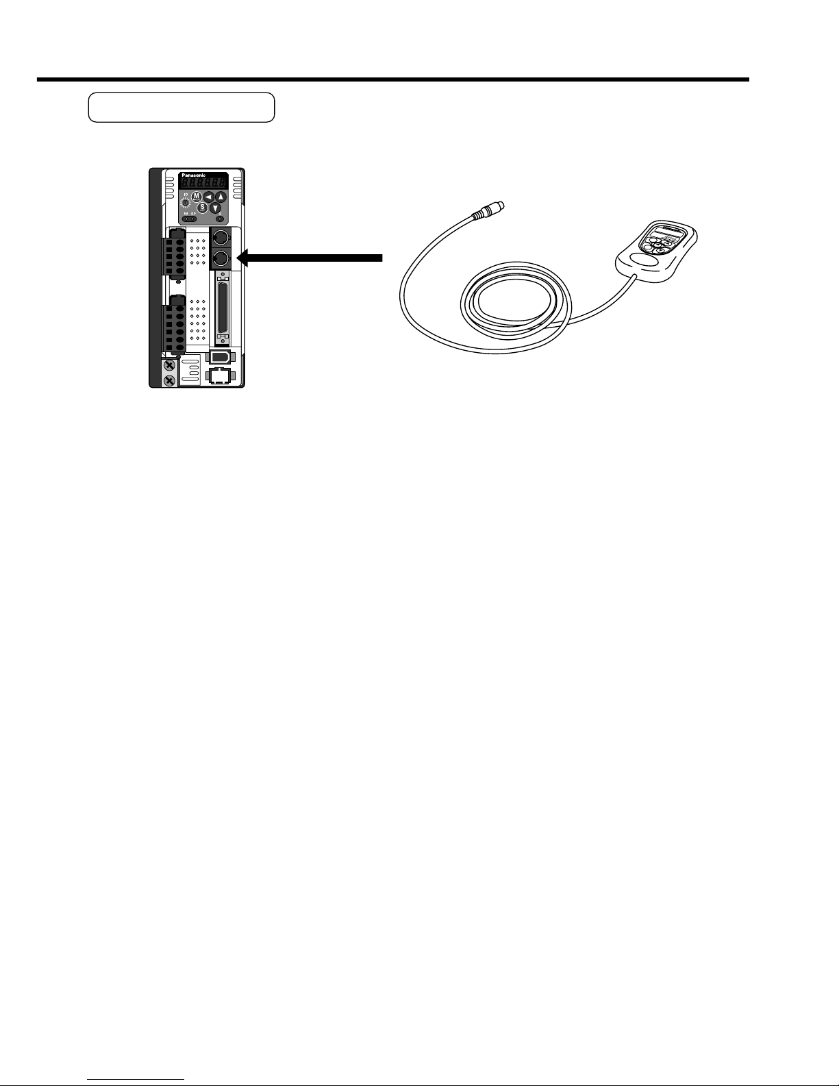
How to Connect
<Remarks>
• Connect the console connector securely to CN X4 connector of the driver.
• Never pull the cable to plug in or plug out.
MODE
SHIFT
SET
S
M
Connect to CN X4.
Page 10
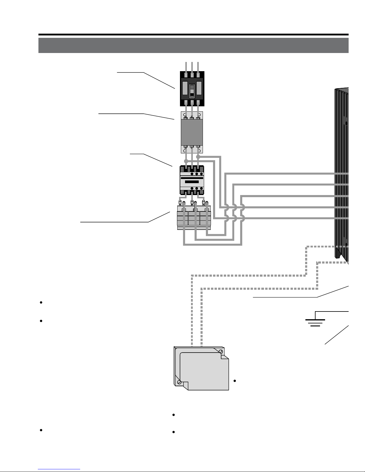
C
ircuit Breaker (NFB)
U
se the circuit breaker matching
c
apacity of the power source to
p
rotect the power lines.
N
oise Filter (NF)
P
revents external noise from the pow-
e
r lines. And reduces an effect of the
n
oise generated by the servo driver.
M
agnetic Contactor (MC)
T
urns on/off the main power of the
s
ervo driver.
U
se a surge absorber together
w
ith this.
•
Never start nor stop the servo mo-
tor with this Magnetic Contactor.
R
eactor (L)
R
educes harmonic current of the
m
ain power.
F
or specifications, refer to the
d
ownloaded Instruction Manual
f
rom our Web Site.
•
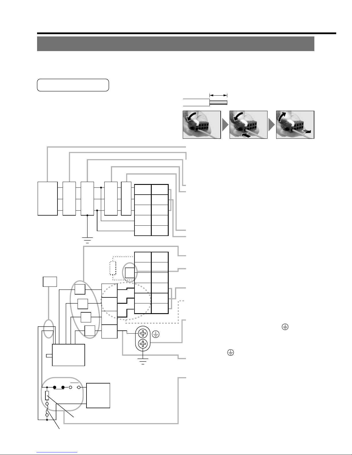
Wiring of the Main Circuit
Ground
(earth)
• Connection to
the Connector, CN X1
(connection to input power)
• Connection to the Connector, CN X2
(connection to external components)
Short bar
Junction cable for motor
Junction cable
for brake
RB1 (Pin-6)
RB2 (Pin-4)
• Wiring to Connector,
CN X2
(Connection to
motor driving
phase and
ground)
L1 (Pin-5)
L2 (Pin-4)
L3 (Pin-3)
L1C (Pin-2)
L2C (Pin-1)
P
in RB1 (6-pin), RB2 (4-pin), and
R
B3 (5-pin)
RB2 and RB3 to be kept shorted for
normal operation.
When the capacity shortage of
the regenerative resister is found,
disconnect a shorting bar between RB2 and RB3, then connect
the external regenerative resister
between RB1 and RB2.
(Note that no regenerative resister
is equipped in Frame A and B type.
Install an external regenerative
resister on incombustible material, such as metal. Follow the same
wiring connection as the above.)
When you connect an external regenerative resister, set up Parameter No. 6C to 1 or 2.
Handle lever
Use this for connector
connection. Store this
after connection for other
occasions.
(see page for connection.)
Regenerative resistor
(optional)
<Remarks>
When you use an external
regenerative resister, install
an external protective apparatus, such as
thermal fuse without fail.
For resistor value and capacity, refer to the
downloaded Instruction Manual from our Web Site.
Thermal fuse and thermostat are built in to the
regenerative resistor (Option). If the thermal
fuse is activated, it will not resume.
U-phase (red)
V-phase (white)
W-phase (black)
3. System Configuration and Wiring
Overall Wiring (Connecting Example of C-frame, 3-phase)
Page 11
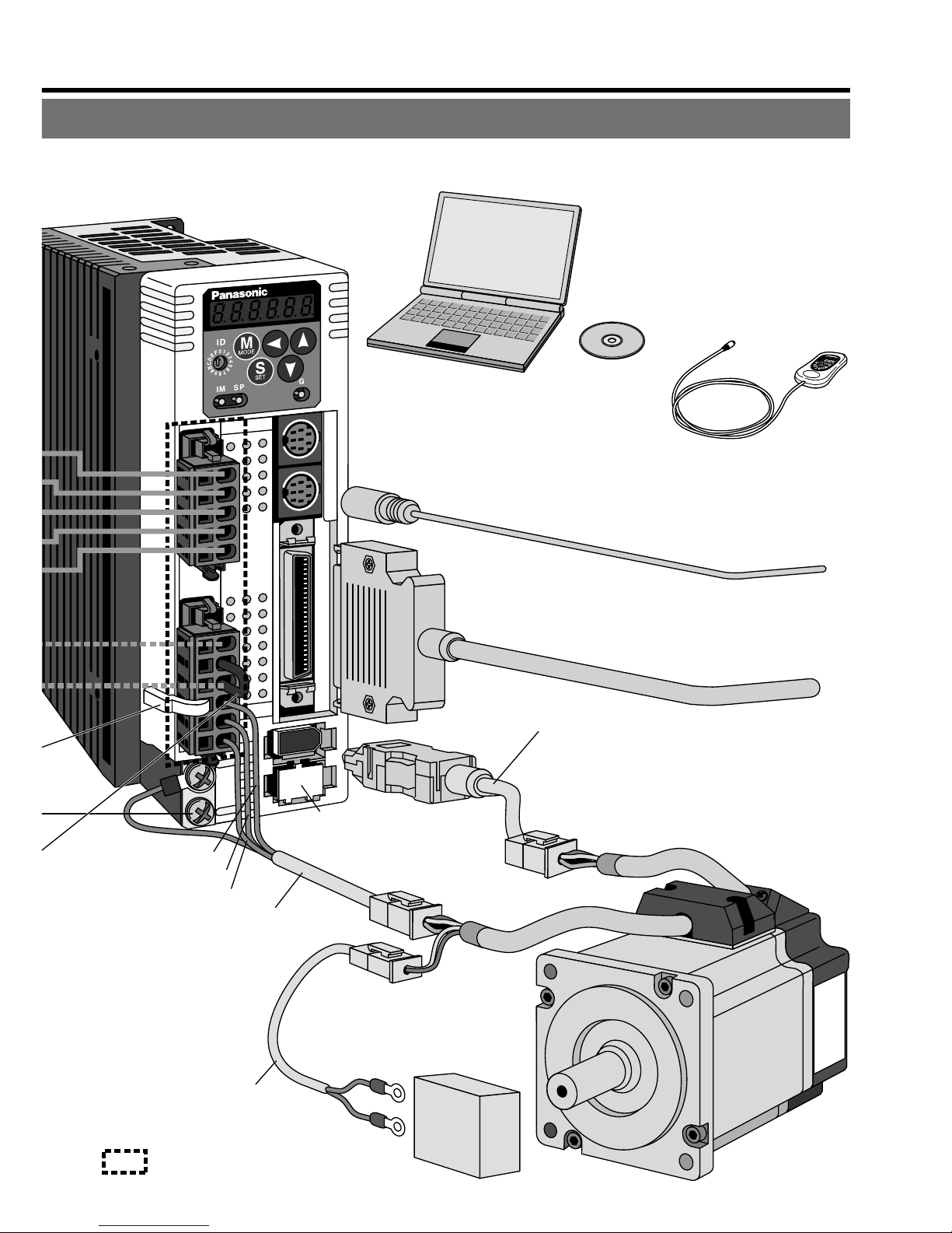
– B11 –– B10 –
X3
X4
X5
X6
X7
• Wiring to Connector, CN X3/X4 (option)
(Connection to PC or host controller)
• Wiring to Connector, CN X5
(Connection to host controller)
• Wiring to Connector, CN X6
(Connection to encoder)
• Wiring to
Connector, CN X7
(Connection to
external scale)
Junction cable for encoder
Junction cable for motor
Junction cable
for brake
DC Power supply for brake
DC24V
(to be supplied by customer)
• Wiring to Connector,
CN X2
(Connection to
motor driving
phase and
ground)
: High voltage
X1
X2
U-phase (red)
V-phase (white)
W-phase (black)
PC (to be supplied by customer)
Setup support software
"PANATERM
®
"
DV0P4460
Console (option)
DV0P4420
Page 12
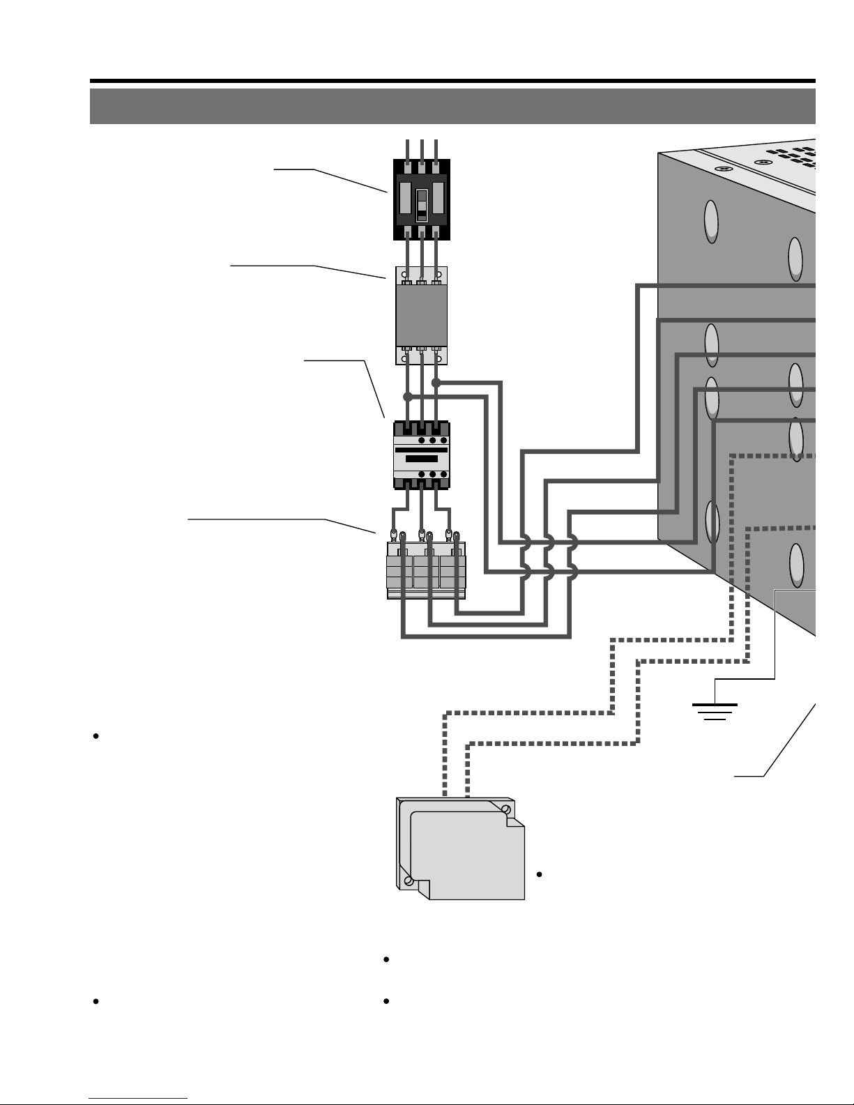
3. System Configuration and Wiring
Overall Wiring (Connecting Example of E-frame)
Ground
(earth)
• Connection
with input
power supply
• Connection to external
components
Short bar
P
B2
L1
L2
L3
r
t
P
in P, B1 and B2...
B1 and B2 to be kept shorted for
normal operation.
When the capacity shortage of
the regenerative resister is
found, disconnect a short bar
between B1 and B2, then con-
nect the external regenerative
resister between P and B2.
Install an external regenerative resister on incombustible
material, such as metal. Follow
the same wiring connection as
the above.
When you connect an external
regenerative resister, set up
Parameter No. 6C to 1 or 2.
Regenerative resistor
(optional)
<Remarks>
When you use an external
regenerative resister, install
an external protective apparatus, such as thermal
fuse without fail.
For resistor value and capacity, refer to the
downloaded Instruction Manual from our Web Site.
Thermal fuse and thermostat are built in to the
regenerative resistor (Option). If the thermal fuse
is activated, it will not resume.
C
ircuit Breaker (NFB)
U
se the circuit breaker matching
c
apacity of the power source to
p
rotect the power lines.
N
oise Filter (NF)
P
revents external noise from the pow-
e
r lines. And reduces an effect of the
n
oise generated by the servo driver.
M
agnetic Contactor (MC)
T
urns on/off the main power of the
s
ervo driver.
U
se a surge absorber together
w
ith this.
•
Never start nor stop the servo mo-
tor with this Magnetic Contactor.
R
eactor (L)
R
educes harmonic current of the
m
ain power.
F
or specifications, refer to the
d
ownloaded Instruction Manual
f
rom our Web Site.
•
Wiring of the Main Circuit
Page 13
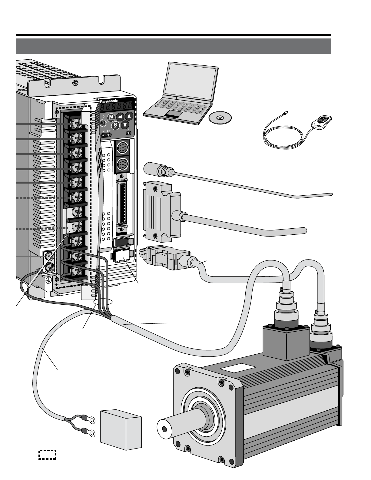
– B13 –– B12 –
: High voltage
X3
X4
X5
X7
X6
• Wiring to Connector, CN X3/X4 (option)
(Connection to PC or host controller)
• Wiring to Connector, CN X5
(Connection to host controller)
Junction cable
for motor
Junction cable for brake
DC Power supply for brake
DC24V
(to be supplied by customer)
U-phase
V-phase
W-phase
X1
• Wiring to Connector, CN X6
(Connection to encoder)
Junction cable
for encoder
From a top
• Wiring to Connector, CN X7
(Connection to external scale)
• Connection to motor driving
phase and ground
PC (to be supplied by customer)
Setup support software
"PANATERM
®
"
DV0P4460
Console (option)
DV0P4420
Page 14
3. System Configuration and Wiring
Connection
Driver
Applicable
motor
Voltage
Rated
output
Required
Power
(at the rated
load)
Noise
filter for
signal
Noise
filter
Surge
absorber
Magnetic
contactor
Cable
diameter
(main circuit)
Cable
diameter
(control circuit)
MADD
MBDD
MCDD
MDDD
MEDD
MSMD
MQMA
MSMD
MQMA
MAMA
MSMD
MQMA
MSMD
MQMA
MAMA
MQMA
MSMD
MAMA
MFMA
MHMA
MAMA
MDMA
MHMA
MGMA
MSMA
MHMA
MDMA
MSMA
MFMA
MDMA
MSMA
MHMA
MFMA
Single
phase,
100V
Single
phase,
200V
Single
phase,
100V
Single
phase,
200V
Single
phase,
100V
Single/
3- phase,
200V
Single/
3- phase,
200V
3- phase,
200V
50W
to 100W
100W
50W
to 200W
100W
200W
100W
200W
400W
200W
400W
750W
400W
500W
750W
1.0kW
900W
1.0kW
1.5kW
2.0kW
2.5kW
approx.
0.4kVA
approx.
0.4kVA
approx.
0.5kVA
approx.
0.3kVA
approx.
0.5kVA
approx.
0.3kVA
approx.
0.5kVA
approx.
0.9kVA
approx.
0.5kVA
approx.
0.9kVA
approx.
1.3kVA
approx.
0.9kVA
approx.
1.1kVA
approx.
1.6kVA
approx.
1.8kVA
approx.
1.8kVA
approx.
1.8kVA
approx.
2.3kVA
approx.
3.3kVA
approx.
3.8kVA
Circuit
breaker
(rated
current)
10A
15A
20A
30A
DV0P4170
DV0P4180
DV0P4220
Connection to exclusive connector
DV0P4190
DV0P1450
DV0P1460
BMFT61041N
(3P+1a)
BMFT61542N
(3P+1a)
BMFT61041N
(3P+1a)
BMFT61542N
(3P+1a)
BMFT61541N
(3P+1a)
BMFT61542N
(3P+1a)
BMFT61842N
(3P+1a)
BMF6352N
(3P+2 a 2b)
0.75 to
2.0mm
2
AWG
14 to 18
2.0mm
2
AWG14
2.0mm
2
AWG14
3.5mm
2
AWG12
0.75mm
2
AWG18
Termina
l
block
M5
11.0 or
smaller
ø5.3
Driver
MFDD
l
Driver and List of Applicable Peripheral Equipments
• Select a single and 3-phase common specifications according to the power source.
• Manufacturer of circuit breaker and magnetic contactor : Matsushita Electric Works.
To comply to EC Directives, install a circuit breaker between the power and the noise
filter without fail, and the circuit breaker should conform to IEC Standards and UL
recognized (Listed and marked).
5000Arms, 240V is the maximum capacity to be delivered to the circuit of 750W or
larger model when the maximum current value of the circuit breaker is limited to 20A.
• For details of noise filters, refer to P.B42, "Noise Filter".
<Remarks>
• Select and use the circuit breaker and noise filter with matching capacity to those of
the power source, considering the load conditions as well.
• Terminal block and protective earth terminal
Use a copper conductor cable with temperature rating of 60˚C or higher.
Protective earth terminal is M4 for A to D-frame, and M5 for E and F-frame.
Larger tightening torque of the screw than the max. value (M4 : 1.2 N
may damage the terminal block.
• Earth cable diameter should be 2.0mm
and 3.5mm
for 4.5kW to 5kW model.
• Use the attached exclusive connectors for A to D-frame, and maintain the peeled off
length of 8 to 9mm.
• Tightening torque of the screws for connector (CN X5) for the connection to the host
to be 0.3 to 0.35 N
at the driver side.
Page 15
– B15 –– B14 –
Connection
Driver
Applicable
motor
Voltage
Rated
output
Required
Power
(at the rated
load)
Noise
filter for
signal
Noise
filter
Surge
absorber
Magnetic
contactor
Cable
diameter
(main circuit)
Cable
diameter
(control circuit)
Circuit
breaker
(rated
current)
MFDD
MGMA
MDMA
MHMA
MSMA
MGMA
MDMA
MHMA
MSMA
MFMA
MGMA
MDMA
MHMA
MSMA
3- phase,
200V
2.0kW
3.0kW
4.0kW
4.5kW
5.0kW
approx.
3.8kVA
approx.
4.5kVA
approx.
6kVA
approx.
6.8kVA
approx.
7.5kVA
approx.
7.5kVA
50A
DV0P3410 DV0P1450 DV0P1460
BMF6352N
(3P+2a2b)
BMF6652N
(3P+2a2b)
3.5mm
2
AWG12
5.3mm
2
AWG10
0.75mm
2
AWG18
Termina
l
block
M5
11.0 or
smaller
ø5.3
• Select a single and 3-phase common specifications according to the power source.
• Manufacturer of circuit breaker and magnetic contactor : Matsushita Electric Works.
To comply to EC Directives, install a circuit breaker between the power and the noise
filter without fail, and the circuit breaker should conform to IEC Standards and UL
recognized (Listed and marked).
5000Arms, 240V is the maximum capacity to be delivered to the circuit of 750W or
larger model when the maximum current value of the circuit breaker is limited to 20A.
• For details of noise filters, refer to P.B42, "Noise Filter".
<Remarks>
• Select and use the circuit breaker and noise filter with matching capacity to those of
the power source, considering the load conditions as well.
• Terminal block and protective earth terminal
Use a copper conductor cable with temperature rating of 60˚C or higher.
Protective earth terminal is M4 for A to D-frame, and M5 for E and F-frame.
Larger tightening torque of the screw than the max. value (M4 : 1.2 N
•
m, M5 : 2.0 N•m)
may damage the terminal block.
• Earth cable diameter should be 2.0mm
2
(AWG14) or larger for 50W to 2.0kW model,
and 3.5mm
2
(AWG12) or larger for 2.5kW to 4.0kW, and 5.3mm2(AWG10) or larger
for 4.5kW to 5kW model.
• Use the attached exclusive connectors for A to D-frame, and maintain the peeled off
length of 8 to 9mm.
• Tightening torque of the screws for connector (CN X5) for the connection to the host
to be 0.3 to 0.35 N
•
m. Larger tightening torque than these may damage the connector
at the driver side.
Page 16
Red
Black
Green
yellow
Motor
Surge absorber
DC
24V
White
NFB
Power
supply
DC power supply
for brake
NF MC
1
2
3
4
U
V
W
E
L1C
L3
L2
L1
L2C
RB1
RB3
RB2
U
V
W
2
3
4
5
1
6
5
4
3
2
1
CN X1
CN X2
L
Yellow
(X2)
Fuse (5A)
Ground resistance : 100Ω max.
For applicable wire,
refer to P.B14 and B15.
• Check the name plate of the driver for power
specifications.
• Provide a circuit breaker, or a leakage breaker.
The leakage breaker to be the one designed for
"Inverter" and is equipped with countermeasures
for harmonics.
• Provide a noise filter without fail.
• Provide a surge absorber to a coil of the Magneti
c
Contactor. Never start/stop the motor with this
Magnetic Contactor.
Connect a fuse in series with the surge absorber
.
Ask the manufacturer of the Magnetic Contactor
for the fuse rating.
• Provide an AC Reactor.
• Connect L1 and L1C, and L3 and L2C at singl
e
phase use (100V and 200V), and don't use L2.
•
Match the colors of the motor lead wires to those of
the corresponding motor output terminals (U,V,W).
•
Don't disconnect the shorting cable between RB2
and RB3 (C and D frame type). Disconnect this only
when the external regenerative register is used.
• Avoid shorting and ground fault. Don't
connect the main power.
*
Connect pin 3 of the connector on the amplifier
side with pin 1 of the connector on the motor side.
• Earth-ground this.
•
Connect the protective earth terminal ( ) of the
driver and the protective earth (earth plate) of the
control panel without fail to prevent electrical shock.
• Don't co-clamp the earth wires to the protective
earth terminal ( ) . Two terminals are provided.
• Don't connect the earth cable to other
inserting slot, nor make them touch.
• Compose a duplex Brake Control Circuit so that
the brake can also be activated by an external
emergency stop signal.
• The Electromagnetic Brake has no polarity.
• For the capacity of the electromagnetic brake and
how to use it, refer to P.B45, "Specifications of
Built-in Holding Brake".
• Provide a surge absorber.
•
Connect a 5A fuse in series with the surge absorber
.
3. System Configuration and Wiring
Wiring of the Main Circuit (A to D-frame)
• Wiring should be performed by a specialist or an authorized personnel.
• Do not turn on the power until the wiring is completed.
Tips on Wiring
1) Peel off the insulation cover of the cable.
(Observe the dimension as the right fig. shows.)
2) Insert the cable to the connector detached
from the driver.(See P.B18 for details.)
3) Connect the wired connector to the driver.
8~9mm
Power
supply
r
.
.
d
.
Wiring of the Main Circuit (E and F-frame)
• Wiring should be performed by a specialist or an authorized personnel.
• Do not turn on the power until the wiring is completed.
Tips on Wiring
1) Take off the cover fixing screws, and detach the terminal cover.
2) Make wiring
Use clamp type terminals of round shape with insulation cover for wiring to the termi-
nal block. For cable diameter and size, rater to "Driver and List of Applicable Periph-
eral Equipments" (P.B14 and B15).
3) Attach the terminal cover, and fix with screws.
Fastening torque of cover fixed screw in less than 0.2 N
Page 17

– B17 –– B16 –
Surge absorber
Motor
DC
24V
Power
supply
DC power supply
for brake
NFB
NF MC
L1
U
V
W
E
L2
L3
r
t
P
B1
B2
U
V
W
L
Ground resistance : 100Ω max.
For applicable wire,
refer to P.B14 and B15.
Red
Black
Green
yellow
Yellow
(X2)
• Check the name plate of the driver for power
specifications.
• Provide a circuit breaker, or a leakage breaker.
The leakage breaker to be the one designed for
"Inverter" and is equipped with countermeasures
for harmonics.
• Provide a noise filter without fail.
• Provide a surge absorber to a coil of the
Magnetic Contactor. Never start/stop the moto
r
with this Magnetic Contactor.
Connect a fuse in series with the surge absorber
.
Ask the manufacturer of the Magnetic Contactor
for the fuse rating.
• Provide an AC Reactor.
• Don't disconnect the short bar between B1 and
B2. Disconnect this only when an external
regenerative register is used.
• Match the colors of the motor lead wires to those
of the corresponding motor output terminals
(U,V,W).
• Avoid shorting and ground fault.
Don't connect the main power.
• Earth-ground this.
• Connect the protective earth terminal ( ) of the
driver and the protective earth (earth plate) of the
control panel without fail to prevent electrical
shock.
• Don't co-clamp the earth wires to the protective
earth terminal ( ) . Two terminals are provided
.
• Don't connect the earth cable to other
inserting slot, nor make them touch.
• Compose a duplex Brake Control Circuit so that
the brake can also be activated by an external
emergency stop signal.
• The Electromagnetic Brake has no polarity.
• For the capacity of the electromagnetic brake an
d
how to use it, refer to P.B47, "Specifications of
Built-in Holding Brake".
• Provide a surge absorber.
•
Connect a 5A fuse in series with the surge absorber
.
White
Fuse (5A)
Wiring of the Main Circuit (E and F-frame)
• Wiring should be performed by a specialist or an authorized personnel.
• Do not turn on the power until the wiring is completed.
Tips on Wiring
1) Take off the cover fixing screws, and detach the terminal cover.
2) Make wiring
Use clamp type terminals of round shape with insulation cover for wiring to the terminal block. For cable diameter and size, rater to "Driver and List of Applicable Peripheral Equipments" (P.B14 and B15).
3) Attach the terminal cover, and fix with screws.
Fastening torque of cover fixed screw in less than 0.2 N
•
m.
Page 18

3. System Configuration and Wiring
•
Follow the procedures below for the wiring connection to the Connector CN X1 and X2
.
How to connect
1
. Peel off the insulation cover of the cable.
(see the right fig for exact length for peeling.)
2
. Insert the cable to the connecter in the following 2 methods.
(a) Using the attached Handle Lever
(b) Using a screw driver (blade width of 3.0 to 3.5 mm)
(a) Using handle lever
* You can pull out the cable by pushing down the spring as the above.
* You can pull out the cable by pushing down the spring as the above.
8 to 9mm
Attach the handle lever
to the handling slot on
the upper portion. Press
down the lever to push
down the spring.
Insert the peeled cable
while pressing down the
lever, until it hits the
insertion slot (round
hole).
Release the lever.
(b) Using screw driver
<CAUTION>
•
Peel off the cable with exact length (8 to 9 mm).
•
Take off the connector from the Servo Driver before making connection.
•
Insert one cable into each one of cable insertion slot.
•
Pay attention to injury by screw driver.
Press the screw driver
to the handling slot on
the upper portion to
push down the spring.
Insert the peeled cable
while pressing down the
screw driver, until it hits the
insertion slot (round hole).
Release the screw
driver.
Wiring method to connector (A to D-frame)
Wiring Diagram
Compose the circuit so that the main circuit power will be shut off when an error occurs.
In Case of Single Phase, 100V (A and B-frame)
In Case of Single Phase, 200V (A and B-frame)
Power supply Single phase, 100V to 115V
Power supply Single phase, 200V to 240V
1 2
3
1 2 3
Page 19

– B19 –– B18 –
Wiring Diagram
Compose the circuit so that the main circuit power will be shut off when an error occurs.
Noise
filter
Main power
supply
Control power
supply
Motor
ALM
37
ALM+
L3
L1C
L2C
RB1
MC
NFB
RB3
RB2
U
V
W
L1
CN X2
Surge absorber
External regenerative resistor
ALM–
36
DC12 to 24V
(±5%)
Red
White
Black
Green
1
2
3
4
1
2
3
4
Motor
connection
CN X5
CN X1
172167-1
Tyco Electronics AMP
172159-1
Tyco Electronics AMP
L
MC
ALMON OFF
Noise
filter
Main power
supply
Control power
supply
Motor
ALM
37
ALM+
L3
L1C
L2C
RB1
MC
NFB
RB3
RB2
U
V
W
L1
CN X2
External regenerative resistor
ALM–
36
DC12 to 24V
(±5%)
Red
White
Black
Green
1
2
3
4
1
2
3
4
Motor
connection
CN X5
CN X1
172167-1
Tyco Electronics AMP
172159-1
Tyco Electronics AMP
L
MC
ALMON OFF
In Case of Single Phase, 100V (A and B-frame)
In Case of Single Phase, 200V (A and B-frame)
Power supply Single phase, 100V to 115V
+10%
–15%
+10%
–15%
Power supply Single phase, 200V to 240V
+10%
–15%
+10%
–15%
Use a reactor for
3-phase
Built-in thermostat of an external
regenerative resistor (light yellow)
MC
Surge absorber
Built-in thermostat of an external
regenerative resistor (light yellow)
MC
Page 20

3. System Configuration and Wiring
PIN No. Application
PIN No. Application
External regenerative resistor
<
Remarks>
W
hen you use single
p
hase, connect the main
p
ower between L1 and
L
3 terminals.
Motor
L2
L3
L1C
L2C
RB1
MC
NFB
RB3
RB2
U
V
W
L1
1
2
3
4
1
2
3
4
(Remove the short wire when you connect
the external regenerative resistor.)
172167-1
Tyco Electronics AMP
172159-1
Tyco Electronics AMP
L
<
Remarks>
W
hen you use single
p
hase, connect the main
p
ower between L1 and L3
t
erminals.
Motor
L2
L3
L1C
L2C
RB1
MC
NFB
RB3
RB2
U
V
W
L1
1
2
3
4
1
2
3
4
(Remove the short wire when you connect
the external regenerative resistor.)
*
172167-1
Tyco Electronics AMP
172159-1
Tyco Electronics AMP
L
A
B
D
C
AHG
CDE
BIF
CBA
IHG
FED
A
JL04V-2E20-4PE-B-R
JL04HV-2E22-22PE-B-R
JL04V-2E20-18PE-B-R
JL04V-2E24-11PE-B-R
U-phase
V-phase
W-phase
Ground
PIN No.
B
C
D
Application
G
H
A
F
I
B
E
D
C
Brake
Brake
NC
U-phase
V-phase
W-phase
Ground
Ground
NC
A Brake
Brake
NC
U-phase
V-phase
W-phase
Ground
Ground
NC
B
C
D
E
F
G
H
I
<Remark>
Do not connect anything to NC.
* When you use motor model of
MSMA, MDMA, MFMA, MHMA
and MGMA, use the connections
as the below table shows.
[Motor portion]
Connector : by Japan Aviation Electronics In
d.
In Case of Single Phase, 200V (C and D-frame)
In Case of 3-Phase, 200V (C and D-frame)
CN X2
CN X1
ALM
37
ALM+
ALM–
36
DC12 to 24V
(±5%)
CN X5
CN X2
CN X1
CN X5
ALM
37
ALM+
ALM–
36
DC12 to 24V
(±5%)
MC
ALMON OFF
MC
ALMON OFF
Use a reactor for
3-phase
Noise
filter
Noise
filter
Main power
supply
Control power
supply
Motor
connection
Main power
supply
Control power
supply
Motor
connection
Power supply Single phase, 200V to 240V
+10%
–15%
+10%
–15%
Power supply 3-phase, 200V to 240V
+10%
–15%
+10%
–15%
Red
White
Black
Green
External regenerative resistor
Red
White
Black
Green
*
Surge absorber
Built-in thermostat of an external
regenerative resistor (light yellow)
MC
Surge absorber
Built-in thermostat of an external
regenerative resistor (light yellow)
MC
.
In Case of 3-Phase, 200V (E and F-frame)
(Remove the short bar when you connect
Power supply 3-phase, 200V to 230V
Page 21

– B21 –– B20 –
Red
White
Black
Green
PIN No. Application
PIN No. Application
[Motor portion]
Connector : by Japan Aviation Electronics Ind
.
In Case of 3-Phase, 200V (E and F-frame)
A
B
D
C
AHG
CDE
BIF
CBA
IHG
FED
A
JL04V-2E20-4PE-B-R
JL04HV-2E22-22PE-B-R
JL04V-2E20-18PE-B-R
JL04V-2E24-11PE-B-R
U-phase
V-phase
W-phase
Ground
PIN No.
B
C
D
Application
G
H
A
F
I
B
E
D
C
Brake
Brake
NC
U-phase
V-phase
W-phase
Ground
Ground
NC
A Brake
Brake
NC
U-phase
V-phase
W-phase
Ground
Ground
NC
B
C
D
E
F
G
H
I
Motor
ALM
37
ALM+
L2
L3
r
t
P
MC
MC
NFB
ALM
ON
OFF
B1
B2
U
V
W
L1
ALM–
DC12 to 24V
(±5%)
(Remove the short bar when you connect
the external regenerative resistor.)
36
L
<Remark>
Do not connect anything to NC.
Power supply 3-phase, 200V to 230V
+10%
–15%
+10%
–15%
Noise
filter
Main power
supply
Control power
supply
Motor
connection
External regenerative resistor
Surge absorber
Built-in thermostat of an external
regenerative resistor (light yellow)
MC
Page 22

Wiring Diagram In case of 17-bit absolute/incremental encoder
Regulator
MSMD 50W to 750W
MAMA 100W to 750W
MQMA 100W to 400W
motor
1
+5V
0V
2
3
4
5
6
4
5
2
3
6
Twisted pair
Junction cable
(by Tyco Electronics, AMP)
172160-1172168-1
(by Tyco Electronics, AMP)
Motor side Driver side
Case
Case
CN X6
CN X6
Black
Purple
White
Light Blue
Regulator
E5V
E0V
E5V
E0V
PS
PS
PS
FG
PS
+5V
0V
motor
(by Japan Aviation Electronics Ind.)
1
2
3
4
5
6
H
G
K
L
Twisted pair
Pin No. of connector
Junction cable
Straight plug
Cable clamp
N/MS3106B20-29S
N/MS3057-12A
Motor side Driver side
E5V
E0V
PS
PS
J
PS
PS
FG
E5V
E0V
MSMA 1kW to 5kW
MDMA 1kW to 5kW
MHMA 500W to 5kW
MFMA 400W to 4.5kW
MGMA 900W to 4.5kW
3. System Configuration and Wiring
MSMD 50W to 750W
MAMA 100W to 750W
MQMA 100W to 400W
MSMA 1kW to 5kW
MDMA 1kW to 5kW
MHMA 500W to 5kW
Wiring to the Connector, CN X6 (Connection to Encoder)
Wiring Diagram In case of 2500P/r incremental encoder
Page 23

– B23 –– B22 –
Wiring Diagram In case of 17-bit absolute/incremental encoder
MSMD 50W to 750W
MAMA 100W to 750W
MQMA 100W to 400W
motor
1
+5V
0V
+5V
0V
2
3
4
5
6
1
battery
battery
2
7
8
4
5
3
Twisted pair
Junction cable
(by Tyco Electronics, AMP)
172161-1172169-1
(by Tyco Electronics, AMP)
Motor side Driver side
Black
Purple
Yellow/Green
White
Light Blue
Pink
Red
E5V
E0V
E5V
E0V
BAT+
BAT–
PS
PS
motor
(Japan Aviation Electronics Industry, Ltd.)
1
2
3
4
5
6
H
G
K
L
J
T
S
Twisted pair
Pin No. of connector
Junction cable
Straight plug
Cable clamp
N/MS3106B20-29S
N/MS3057-12A
Motor side Driver side
E5V
E0V
PS
PS
PS
PS
FG
E5V
E0V
PS
PS
Case
Case
BAT+
BAT–
FG
Regulator
Regulator
CN X6
CN X6
MSMA 1kW to 5kW
MDMA 1kW to 5kW
MHMA 500W to 5kW
MFMA 400W to 4.5kW
MGMA 900W to 4.5kW
Page 24

Wiring Example of Velocity Control Mode
7
4.7k
Ω
COM+
OA+
OA
-
OB+
OB
-
OZ+
OZ
-
GND
CZ
SPR/TRQR
GND
CCWTL/TRQR
GND
CWTL
SP
IM
21
22
48
24
25
19
49
23
3.83k
Ω
3.83k
Ω
20k
Ω
10k
Ω
10k
Ω
1k
Ω
1k
Ω
INTSPD1
INTSPD2
SRV-ON
GAIN
INTSPD3
ZEROSPD
C-MODE
A-CLR
CCWL
CWL
S-RDY+
S-RDY
-
ALM+
AT
-SPEED
+
BRKOFF
+
BRKOFF
-
TLC
V
DC
12 to 24V
ZSP
COM
-
FG
AT
-SPEED
-
ALM
-
33
30
29
27
32
31
9
8
35
34
37
36
39
38
11
10
40
12
41
50
Servo-ON input
Gain switching input
28
Divider
Alarm clear input
A-phase output
B-phase output
Z-phase output
Z-phase output (open collector)
Servo-Ready output
Servo alarm output
Positioning complete
output
Brake release output
T
orque in-limit output
(Select with Pr09)
(Select with Pr0A)
14
15
16
17
18
43
42
26
Speed zero clamp input
V
elocity command
input
(0 to
±
10V)
CCW torque limit
input
(0 to
±
10V)
CW torque limit
input
(-10 to 0V)
V
elocity monitor output
T
orque monitor output
330
Ω
330
Ω
330
Ω
CN X5
Selection 1 input of
internal command speed
Selection 2 input of
internal command speed
Slection 3 input of
internal command speed
Control mode switching
input
CCW over-travel inhibition
input
CW over-travel inhibition
input
Zero speed detection output
( represents twisted pair.)
Wiring for Typical Control Modes to the Connector CN X5
Wiring Example of Position Control Mode
3. System Configuration and Wiring
14
15
16
43
18
42
In case of open collector I/F
(1) When you use the external
resistor with 12V and 24V
power supply
(2) When you do not use the
external resistor with 24V
power supply
CCW torque limit input
(0 to +10V)
CW torque limit input
(
-
10 to +10V)
V
elocity monitor output
T
orque monitor output
( represents twisted pair.)
Command
pulse
input A
(Use with 500kpps
or less.)
7
4.7k
Ω
COM+
PULS2
SIGN1
SIGN2
GND
OA+
OA
OB+
OB
OZ+
OZ
GND
CZ
SPR/TRQR
GND
CCWTL/TRQR
GND
CWTL
SP
IM
3
2
1
4
5
6
13
21
22
48
24
25
19
49
23
3.83k
Ω
3.83k
Ω
43kΩ
2kΩ
2kΩ
43kΩ
220Ω
20k
Ω
220
Ω
330
Ω
330
Ω
330
Ω
220
Ω
2.2k
Ω
2.2k
Ω
10k
Ω
10k
Ω
1k
Ω
1k
Ω
PULS1
OPC2
OPC1
INH
CL
SRV-ON
GAIN
DIV
VS-SEL
C-MODE
A-CLR
CCWL
CWL
S-RD Y
+
S-RDY
-
ALM+
COIN+
BRKOFF
+
BRKOFF
-
TLC
V
DC
12 to 24V
ZSP
COM
-
SIGNH1
SIGNH2
GND
PULSH1
PULS
PULSH2
FG
COIN
-
ALM
-
33
30
29
27
28
32
31
9
8
35
34
37
36
39
38
11
10
40
12
41
44
45
13
50
Servo-ON input
Gain switching input
Electronic gear
switching input
Control mode
switching input
26
Damping control
switching input
Divider
Alarm clear input
CCW over-travel
inhibition input
A-phase
output
B-phase
output
Z-phase
output
Z-phase output (open collector)
CW over-travel
inhibition input
Servo-Ready output
Servo-Alarm output
Positioning complete output
Brake release output
T
orque in-limit output
(Select with Pr09)
Zero speed detection output
(Select with Pr0A)
Deviation counter
clear input
Command pulse
inhibition input
Command pulse input B
(Use with 2Mpps or less.)
PULS1
PULS2
SIGN1
GND
V
DC
12V
24V
pecifications
of R
1kΩ
1/2W
2kΩ
1/2W
SIGN2
220
Ω
220
Ω
V
DC
R
R
3
4
5
6
13
PULS2
GND
SIGN2
OPC1
OPC2
220
Ω
220
Ω
24V
DC
1
4
2
6
13
2.2k
Ω
2.2k
Ω
V
DC
-
1.5
R
+
220
=10mA
.
.
CN X5
SIGN
46
47
43kΩ
2kΩ
2kΩ
43kΩ
220Ω
Page 25

– B25 –– B24 –
Wiring Example of Velocity Control Mode
7
4.7k
Ω
COM+
OA+
OA
OB+
OB
OZ+
OZ
GND
CZ
SPR/TRQR
GND
CCWTL/TRQR
GND
CWTL
SP
IM
21
22
48
24
25
19
49
23
3.83k
Ω
3.83k
Ω
20k
Ω
10k
Ω
10k
Ω
1k
Ω
1k
Ω
INTSPD1
INTSPD2
SRV-ON
GAIN
INTSPD3
ZEROSPD
C-MODE
A-CLR
CCWL
CWL
S-RDY+
S-RDY
-
ALM+
AT
-SPEED
+
BRKOFF
+
BRKOFF
-
TLC
V
DC
12 to 24V
ZSP
COM
FG
AT
-SPEED
-
ALM
-
33
30
29
27
32
31
9
8
35
34
37
36
39
38
11
10
40
12
41
50
Servo-ON input
Gain switching input
28
Divider
Alarm clear input
A-phase output
B-phase output
Z-phase output
Z-phase output (open collector)
Servo-Ready output
Servo alarm output
Positioning complete
output
Brake release output
T
orque in-limit output
(Select with Pr09)
(Select with Pr0A)
14
15
16
17
18
43
42
26
Speed zero clamp input
V
elocity command
input
(0 to
±
10V)
CCW torque limit
input
(0 to
±
10V)
CW torque limit
input
(-10 to 0V)
V
elocity monitor output
T
orque monitor output
330
Ω
330
Ω
330
Ω
CN X5
Selection 1 input of
internal command speed
Selection 2 input of
internal command speed
Slection 3 input of
internal command speed
Control mode switching
input
CCW over-travel inhibition
input
CW over-travel inhibition
input
Zero speed detection output
( represents twisted pair.)
Page 26

3. System Configuration and Wiring
7
4.7k
Ω
COM+
OA+
OA
OB+
OB
OZ+
OZ
GND
CZ
SPR/TRQR
GND
CCWTL/TRQR
GND
CWTL
SP
IM
21
22
48
24
25
19
14
15
16
17
43
18
42
49
23
3.83k
Ω
3.83k
Ω
20k
Ω
10k
Ω
10k
Ω
1k
Ω
1k
Ω
INH
CL
SRV-ON
GAIN
DIV
ZEROSPD
C-MODE
A-CLR
CCWL
CWL
S-RDY+
S-RDY
-
ALM+
AT
-SPEED
+
BRKOFF
+
BRKOFF
-
TLC
ZSP
COM
FG
AT
-SPEED
-
ALM
-
33
30
29
27
28
26
32
31
9
8
35
34
37
36
39
38
11
10
40
12
41
50
Servo-ON input
Gain switching input
Divider
Alarm clear input
T
orque command input or
velocity limit input (0 to
±
10V)
V
elocity monitor output
T
orque monitor output
Z-phase output (open collector)
Servo-Ready output
Servo-Alarm output
At-speed signal output
Brake release output
T
orque in-limit output
(Select with Pr09)
Zero speed detection output
(Select with Pr0A)
Wiring example when control mode Pr02=0 or Pr5B=1,
CCWTL/TRQR
GND
16
17
CW torque limit input
(0 to
±
10V)
330
Ω
330
Ω
330
Ω
Speed zero clamp
input
CN X5
<Remarks>
In case Pr5B=0,
enter a speed limit value to
4th speed of speed setup (Pr56).
Control mode
switching input
CCW over-travel
inhibition input
CW over-travel
inhibition input
V
DC
12
to
24V
A-phase
output
B-phase
output
Z-phase
output
( represents twisted pair.)
Select with Pr5B.
Wiring Example of Torque Control Mode
4. Parameter
Outline of Parameter
This driver is equipped with various parameters to set up its characteristics and func-
tions. This section describes the function and purpose of each parameter. Read and
comprehend very well so that you can adjust this diver in optimum condition for your
running requirements.
How to Set
• You can refer and set up the parameter with either one of the following.
1) front panel of the driver
2) combination of the setup support software, "PANATERM
glish/Japanese version) and PC.
3) console (DV0P4420, option)
<Note>
For setup of the parameters on PC screen, refer to the instruction manual of the
"PANATERM
Setup with the Front Panel
.
t
it
Page 27

– B27 –– B26 –
4. Parameter
Outline of Parameter
This driver is equipped with various parameters to set up its characteristics and functions. This section describes the function and purpose of each parameter. Read and
comprehend very well so that you can adjust this diver in optimum condition for your
running requirements.
How to Set
• You can refer and set up the parameter with either one of the following.
1) front panel of the driver
2) combination of the setup support software, "PANATERM
®
" (Option, DV0P4460: En-
glish/Japanese version) and PC.
3) console (DV0P4420, option)
<Note>
For setup of the parameters on PC screen, refer to the instruction manual of the
"PANATERM
®
".
Setup with the Front Panel
Mode switching button (valid at SELECTION display)
Press this to switch 5 kinds of mode.
1) Monitor Mode
2) Parameter Set up Mode
3) EEPROM Write Mode
4) Auto-Gain Tuning Mode
5) Auxiliary Function Mode
Display LED (6-digit)
All of LED will flash when error occurs,
and switch to error display screen.
All of LED will flash slowly when warning occurs.
Shifting of the digit for data changing to higher digit
.
(Valid to the digit whose decimal point flashes.)
Press these to change display and data, selec
t
parameters and execute actions.
(Change/Selection/Execution is valid to the dig
it
which decimal point flashes.)
Numerical value increases by pressing , ,
decreases by pressing .
SET Button (valid at any time)
Press this to switch SELECTION and
EXECUTTION display.
Page 28

4. Parameter
Display LED (6-digit)
All of LED will flash when error occurs, and switch t
o
error display screen.
Displays ID No. (address) of selected driver (in 2 digits).
The value set in Pr00(address) is ID No. Parameter No
.
is displayed (2 digits) at parameter setup mode.
Press this to shift the digit for data change.
Press these to change data or execute selected actio
n
of parameter.
Numerical value increases by pressing , ,
decreases by pressing .
SET Button
Press this to shift each mode which is selected b
y
mode switching button to EXECUTION display.
M
ode Switching Button Press this to switch 6 kinds of mode.
1) Monitor mode 4) Normal auto-gain tuning mode
2) Parameter setup mode 5) Auxiliary function mode
3) EEPROM write mode 6) Copy mode
Outline of PANATERM
®
With the PANATERM®, you can execute the followings.
1) Setup and storage of parameters, and writing to the memory (EEPROM).
2) Monitoring of I/O and pulse input and load factor.
3) Display of the present alarm and reference of the error history.
4) Data measurement of the wave-form graphic and bringing of the stored data.
5) Normal auto-gain tuning
6) Frequency characteristic measurement of the machine system.
Setup with the Console
How to Connect
e,
<Remarks>
• Connect the console connector to the connector, CN X4 of the driver securely.
• Do not pull the cable to insert/unplug.
Page 29

– B29 –– B28 –
How to Connect
Connect to CN X4
Connect to CN X4
RS232 connection cable (option)
DV0P1960 (for DOS/V machines)
Console
DV0P4420 (option)
Setup disc of setup support softwar
e,
PANATERM
®
• DV0P4460 :
English/Japanese version (option)
<Remarks>
• Connect the console connector to the connector, CN X4 of the driver securely.
• Do not pull the cable to insert/unplug.
Page 30

4. Parameter
Parameters for Functional Selection
<Notes>
•
For parameters with suffix of "*1", change will be validated after the reset of the control power.
• For parameters which default values are parenthesized by "< >", default value varies
automatically by the real-time auto-gain tuning function. Set up Pr21 (Setup of Real-
time auto-gain tuning mode) to 0 (invalid) when you want to adjust manually.
* In this documentation, each mode is represented by the following symbols
P : Position control, S : Velocity control, T : Torque control, F : Full-closed control,
P/S : Position (1st),/Velocity (2nd) control, P/T : Position (1st)/Torque (2nd) control,
S/T : Velocity (1st)/Torque (2nd) control.
l
Parameter
(Pr )
00
01
02
03
04
05
06
07
08
09
0A
0B
0C
0D
0E
0F
Parameters for Adjustment of Time Constant for Gains and Filters
l
Parameter
(Pr )
10
11
12
13
14
15
16
17
Composition and List of Parameters
Group Outline
Parameter No.
(Pr )
Functional selection
Adjustment
Position (Step)
Control
Velocity Control,
Torque Control
Sequence
Full-Closed Control
00 to 0F
10 to 1F,
27 to 2E
20 to 26, 2F
30 to 3F
40 to 4F
50 to 5A,
74 to 77
5B to 5F
60 to 6F
70 to 73
78 to 7F
You can select a control mode, designate I/O
signals and set up a baud rate.
You can set up servo gains (1st and 2nd) o
f
position, velocity, integration, etc, and time
constants of various filters.
Parameters related to Real Time Auto-Gain Tuning. You
can set up a mode and select a mechanical stiffness.
You can set up parameters related to gain
switching(1st 2nd)
You can set up an input form, directional selection
of command pulses, dividing of encoder outpu
t
pulse and set up a division multiplier ratio o
f
command pulse.
You can set up an input gain of command pulse
,
reverse polarity and adjust offset. You can also se
t
up internal speeds (1 to 8th speed), acceleration
/
deceleration time.
You can set an input gain, reverse polarity and se
t
up a torque limit of torque command.
You can set up detecting conditions of output signals
,
such as positioning-complete and zero-speed.
You can also set up a deceleration/stop action a
t
main power-off, at alarm output and at servo-off
,
and clear condition of the deviation counter.
You can set up actions of protective functions.
You can set up dividing of external scale.
• In this document, following symbols represent each mode.
* When you select the combination mode of 3, 4 or 5, you can select either 1st or 2nd
with control mode switching input (C-MODE).
when C-MODE is open : 1st mode selection
when C-Mode is closed: 2nd mode selection
Do not enter the command 10ms before/after the switching.
P
S
T
F
Symbol
0
1
2
6
Position control
Velocity control
Torque control
Full-Closed control
Control mode
P/S
P/T
S/T
Symbol
3*
4*
5*
Setup valu
e
of
Pr02
Position (1st)/Velocity (2nd) control
Position (1st)/Torque (2nd) control
Velocity (1st)/Torque (2nd) control
Control mode
Setup value
of
Pr02
Page 31

– B31 –– B30 –
Parameters for Functional Selection
<Notes>
•
For parameters with suffix of "*1", change will be validated after the reset of the control power.
• For parameters which default values are parenthesized by "< >", default value varies
automatically by the real-time auto-gain tuning function. Set up Pr21 (Setup of Realtime auto-gain tuning mode) to 0 (invalid) when you want to adjust manually.
* In this documentation, each mode is represented by the following symbols
P : Position control, S : Velocity control, T : Torque control, F : Full-closed control,
P/S : Position (1st),/Velocity (2nd) control, P/T : Position (1st)/Torque (2nd) control,
S/T : Velocity (1st)/Torque (2nd) control.
Set up of parameter Range Unit
Related contro
l
mode
Parameter
No.
(Pr )
Default
00*1
01
*
1
02
*
1
03
04
*
1
05
06
07
08
09
0A
0B
*
1
0C
*
1
0D
*
1
0E
*
1
0F
0 to 15
0 to 17
0 to 6
0 to 3
0 to 2
0 to 3
0 to 2
0 to 9
0 to 12
0 to 8
0 to 8
0 to 2
0 to 5
0 to 5
0 to 1
–
1
1
1
1
1
0
0
3
0
0
1
1
2
2
0
–
–
–
–
–
–
–
–
–
–
–
–
–
–
–
–
–
all
all
all
P, S, F
all
S
S, T
all
all
all
all
all
all
all
all
–
Address of axis
Initial display of LED
Setup of control mode
Selection of torque limit
Setup of over-travel inhibit input
Switching of Internal/External speed setup
Selection of ZEROSPD input
Selection of speed monitor (SP)
Selection of torque monitor (IM)
Selection of TLO output
Selection of ZSP output
Setup of absolute encoder
Baud rate setup of RS232
Baud rate setup of RS485
Setup of front panel lock
(For manufacturer's use)
Parameters for Adjustment of Time Constant for Gains and Filters
Set up of parameter Range Unit
Related contro
l
mode
Parameter
No.
(Pr )
Default
10
11
12
13
14
15
16
17
0 to 3000
1 to 3500
1 to 1000
0 to 5
0 to 2500
–2000 to 2000
0 to 6400
–
<63> <32>
<35> <18>
<16> <31>
<0>
<65>
<126>
<300>
<50>
–
1/s
Hz
ms
–
0.01ms
0.1%
0.01ms
–
P, F
all
all
all
all
P, F
P, F
–
1st gain of position loop
1st gain of velocity loop
1st time constant of velocity loop integration
1st filter of velocity detection
1st time constant of torque filter
Velocity feed forward
Time constant of feed forward filter
(For manufacturer's use)
A to
C-frame
D to
F-frame
Page 32

Parameters for Adjustment (2nd Gain Switching Function)
<Notes>
• For parameters with suffix of "*1", change will be validated after the reset of the con-
trol power.
• For parameters which default values are parenthesized by "< >", default value varies
automatically by the real-time auto-gain tuning function. Set up Pr21 (Setup of Real-
time auto-gain tuning mode) to 0 (invalid) when you want to adjust manually.
4. Parameter
Parameters for Adjustment of Time Constant for Gains and Filters
Parameters for Auto-Gain Tuning
Set up of parameter Range Unit
Related contro
l
mode
Parameter
No.
(Pr )
Default
18
19
1A
1B
1C
1D
1E
1F
27
28
29
2A
2B
2C
2D
2E
0 to 3000
1 to 3500
1 to 1000
0 to 5
0 to 2500
100 to 1500
0 to 4
–
0 to 1
100 to 1500
0 to 4
0 to 99
0 to 2000
–200 to 2000
0 to 2000
–200 to 2000
<73> <38>
<35> <18>
<1000>
<0>
<65>
<126>
1500
2
–
<0>
1500
2
0
0
0
0
0
1/s
Hz
ms
–
0.01ms
Hz
–
–
–
Hz
–
–
0.1Hz
–
0.1Hz
–
P, F
all
all
all
all
all
all
–
P, S
all
all
all
P, F
P, F
P, F
P, F
2nd gain of position loop
2nd gain of velocity loop
2nd Time constant of velocity loop integration
2nd filter of velocity detection
2nd torque filter time constant
1st notch frequency
Selection of 1st notch width
(For manufacturer's use)
Setup of instantaneous velocity observer
2nd notch frequency
Selection of 2nd notch width
Selection of 2nd notch depth
1st damping frequency
Setup of 1st damping filter
2nd damping frequency
Setup of 2nd damping filter
A to
C-frame
D to
F-frame
Set up of parameter Range Unit
Related contro
l
mode
Parameter
No.
(Pr )
20
21
22
23
24
25
26
2F*2
0 to 10000
0 to 7
0 to 15
0 to 2
0 to 2
0 to 7
0 to 1000
0 to 64
<250>
1
4 1
1
0
0
10
0
%
–
–
–
–
–
0.1rev
–
all
all
all
P, S, F
P, F
all
P, F
P, S, F
Inertia ratio
Setup of real-time auto-gain tuning mode
Mechanical stiffness at real-time auto-gain tuning
Setup of adaptive filter mode
Selection of damping filter switching
Setup of action at normal mode auto-gain tuning
Setup of software limit
Adaptive filter frequency
Default
A to
C-frame
D to
F-frame
l
Parameter
(Pr )
30
31
32
33
34
35
36
37
38
39
3A
3B
3C
3D
3E
3F
Parameters for Position Control
l
Parameter
(Pr )
40
41
42
43
44
45
46
47
*2 this parameter will be automatically set up when the adaptive filter is validated (Pr23,
“Setup of adaptive filter mode” is “1”, and you cannot set this up at your discretion.
Set up Pr23, “Setup of adaptive filter mode” to “0” (invalid) to clear this parameter.
* In this documentation, each mode is represented by the following symbols
P : Position control, S : Velocity control, T : Torque control, F : Full-closed control,
P/S : Position (1st),/Velocity (2nd) control, P/T : Position (1st)/Torque (2nd) control,
S/T : Velocity (1st)/Torque (2nd) control.
Page 33

– B33 –– B32 –
Parameters for Adjustment (2nd Gain Switching Function)
<Notes>
• For parameters with suffix of "*1", change will be validated after the reset of the control power.
• For parameters which default values are parenthesized by "< >", default value varies
automatically by the real-time auto-gain tuning function. Set up Pr21 (Setup of Realtime auto-gain tuning mode) to 0 (invalid) when you want to adjust manually.
Set up of parameter Range Unit
Related contro
l
mode
Parameter
No.
(Pr )
Default
30
31
32
33
34
35
36
37
38
39
3A
3B
3C
3D
3E
3F
0 to 1
0 to 10
0 to 10000
0 to 20000
0 to 20000
0 to 10000
0 to 5
0 to 10000
0 to 20000
0 to 20000
–
–
–
0 to 500
–
–
<1>
<0>
<30>
<50>
<33>
<20>
<0>
0
0
0
–
–
–
300
–
–
–
–
166µs
–
–
–
166µs
–
–
–
–
–
r/min
–
–
all
all
all
all
all
P, F
S, T
S, T
S, T
S, T
–
–
–
all
–
–
Setup of 2nd gain
1st mode of control switching
1st delay time of control switching
1st level of control switching
1st hysteresis of control switching
Time for position gain switching
2nd mode of control switching
2nd delay time of control switching
2nd level of control switching
2nd hysteresis 0f control switching
(For manufacturer's use)
(For manufacturer's use)
(For manufacturer's use)
Setup of JOG speed
(For manufacturer's use)
(For manufacturer's use)
(1+Setup value)
x 166µs
Parameters for Position Control
Set up of parameter Range Unit
Related contro
l
mode
Parameter
No.
(Pr )
Default
40*1
41
*
1
42
*
1
43
44
*
1
45
*
1
46
*
1
47
*
1
0 to 1
0 to 1
0 to 3
0 to 1
1 to 32767
0 to 32767
0 to 3
0 to 32767
0
0
1
1
2500
0
0
0
–
–
–
–
–
–
–
–
P, F
P, F
P, F
P, F
all
all
all
F
Selection of command pulse input
setup of rotational direction of command pulse
setup of command pulse input mode
Canceling of command pulse prohibition input
Numerator of pulse output division
Denominator of pulse output division
Logic reversal of pulse output
Setup of Z-phase of external scale
Page 34

Parameters for Sequence
4. Parameter
Parameters for Velocity/Torque control
Set up of parameter Range Unit
Related contro
l
mode
Parameter
No.
(Pr )
Default
50
51
52
53
54
55
56
74
75
76
77
57
58
59
5A
5B
5C
5D
5E
5F
10 to 2000
0 to 1
–2047 to 2047
–20000 to 20000
–20000 to 20000
–20000 to 20000
–20000 to 20000
–20000 to 20000
–20000 to 20000
–20000 to 20000
–20000 to 20000
0 to 6400
0 to 5000
0 to 5000
0 to 500
0 to 1
10 to 100
0 to 1
0 to 500
0 to 500
500
1
0
0
0
0
0
0
0
0
0
0
0
0
0
0
30
0
<500>
*
3
<500>
*
3
(r/min)/V
–
0.3mV
r/min
r/min
r/min
r/min
r/min
r/min
r/min
r/min
0.01ms
2ms
–
–
%
%
S, T
S
S, T
S
S
S
S, T
S
S
S
S
S, T
S
S
S
T
T
T
all
P, S, F
Input gain of speed command
Input reversal of speed command
Offset of speed command
1st speed of speed setup
2nd speed of speed setup
3rd speed of speed setup
4th speed of speed setup
5th speed of speed setup
6th speed of speed setup
7th speed of speed setup
8th speed of speed setup
Setup of speed command filter
Setup of acceleration time
Setup of deceleration time
Setup of sigmoid acceleration/deceleration time
Selection of torque command
Input gain of torque command
Input reversal of torque command
Setup of 1st torque limit
Setup of 2nd torque limit
2ms/
(1000r/min)
2ms/
(1000r/min)
0.1V /
rated torque
l
Parameter
(Pr )
60
61
62
63
64
65
66
67
68
69
6A
6B
6C
6D
6E
6F
70
71
72
73
<Notes>
• For parameters with suffix of "*1", change will be validated after the reset of the con-
trol power.
*3 Defaults of Pr5E and Pr5F vary depending on the combination of the driver and the motor.
Set up of parameter Range Unit
Related contro
l
mode
Parameter
No.
(Pr )
Default
48
49
4A
4B
4C
4D
*
1
4E
4F
0 to 10000
0 to 10000
0 to 17
1 to 10000
0 to 7
0 to 31
0 to 2
–
0
0
0
10000
1
0
1
–
–
–
–
–
–
–
–
–
P, F
P, F
P, F
P, F
P, F
P, F
P, F
–
1st numerator of electronic gear
2nd numerator of electronic gear
Multiplier for numerator of electronic gear
Denominator of electronic gear
Setup of smoothing filter for primary delay
Setup of FIR smoothing
Counter clear input mode
(For manufacturer's use)
* In this documentation, each mode is represented by the following symbols
P : Position control, S : Velocity control, T : Torque control, F : Full-closed control,
P/S : Position (1st),/Velocity (2nd) control, P/T : Position (1st)/Torque (2nd) control,
S/T : Velocity (1st)/Torque (2nd) control.
Parameters for Full-Closed Control
l
Parameter
(Pr )
78
79
7A
7B
7C
7D
7E
7F
Page 35

– B35 –– B34 –
Parameters for Sequence
Set up of parameter Range Unit
Related contro
l
mode
Parameter
No.
(Pr )
Default
60
61
62
63
64
65
66
*
1
67
68
69
6A
6B
6C
*
1
6D
*
1
6E
6F
70
71
72
73
0 to 32767
10 to 20000
10 to 20000
0 to 3
–
0 to 1
0 to 2
0 to 9
0 to 3
0 to 9
0 to 100
0 to 100
0 to 3
35 to 1000
0 to 500
–
0 to 32767
0 to 100
0 to 500
0 to 20000
131
50
1000
0
–
1
0
0
0
0
0
0
35
0
–
25000
0
0
0
Pulse
r/min
r/min
–
–
–
–
–
–
–
2ms
2ms
–
2ms
–
–
256Pulse
0.1V
%
r/min
P, F
all
S, T
P, F
–
all
all
all
all
all
all
all
all
all
all
–
P, F
S, T
all
all
In-position (positioning complete) range
Zero speed
At-speed (arrived speed)
Setup of in-position output
(For manufacturer's use)
Selection of LV-trip at main power off
Sequence at run-prohibition
Sequence at main power off
Sequence at alarm
Sequence at servo-off
Setup of mechanical brake action at stall
Setup of mechanical brake action in motion
Selection of external regenerative resister
Detection time of main power shut-off
Setup to torque at emergency stop
(For manufacturer's use)
Excess setup of positional deviation
Excess setup of analog input
Setup of over-load level
Setup of over-speed level
A, B-frame : 3,
C,D,E-frame : 0
<Notes>
• For parameters with suffix of "*1", change will be validated after the reset of the control power.
*3 Defaults of Pr5E and Pr5F vary depending on the combination of the driver and the motor.
Parameters for Full-Closed Control
Set up of parameter Range Unit
Related contro
l
mode
Parameter
No.
(Pr )
Default
78*1
79*1
7A*1
7B*1
7C*1
7D
7E
7F
0 to 32767
0 to 17
1 to 32767
1 to 10000
0 to 1
–
–
–
0
0
10000
100
0
–
–
–
–
–
–
–
–
–
–
F
F
F
F
F
–
–
–
Numerator of external scale division
Numerator multiplier of external scale division
Denominator of external scale division
Excess setup of hybrid deviation
Reversal of direction of external scale
(For manufacturer's use)
(For manufacturer's use)
(For manufacturer's use)
16 X external
scale pulses
Page 36

5. Protective Functions
Protective Function (What Is Error Code ?)
• Various protective functions are equipped in the driver. When these are triggered, the
motor will stall due to error, the driver will turn the Servo-Alarm output (ALM) to off
(open).
• Error status ands their measures
• During the error status, the error code No. will be displayed on the front panel LED,
and you cannot turn Servo-ON.
• You can clear the error status by turning on the alarm clear input (A-CLR) for 120ms
or longer.
• When overload protection is triggered, you can clear it by turning on the alarm clear
signal (A-CLR) 10 sec or longer after the error occurs. You can clear the time characteristics by turning off the connection between L1C and L2C or r and t of the control
power supply of the driver.
• You can clear the above error by operating the front panel keys.
• You can also clear the above error by operating the "PANATERM
®
".
<Remarks>
• When the protective function with a prefix of "*" in the protective function table is
triggered, you cannot clear with alarm clear input (A-CLR). For resumption, shut off
the power to remove the cause of the error and re-enter the power.
• Following errors will not be stored in the error history.
Control power supply under-voltage protection (Error code No. 11)
Main power supply under-voltage protection (Error code No. 13)
EEPROM parameter error protection (Error code No. 36)
EEPROM check code error protection (Error code No. 37)
Over-travel prohibition input protection (Error code No. 38)
Motor self-recognition error protection (Error code No. 95)
11
12
13
14
15
16
18
21
23
24
25
26
27
28
29
34
35
36
37
38
Error
code
No.
Page 37

– B37 –– B36 –
11
12
13
14
15
16
18
21
23
24
25
26
27
28
29
34
35
36
37
38
Protective function
Error
code
No.
39
40
41
42
44
45
47
48
49
50
51
52
53
54
55
65
66
95
Other
No.
Protective function
Error
code
No.
Control power supply under- voltage
protection
Analog input excess protection
Absolute system down error
protection
*
Absolute counter over error
protection
Absolute over-speed error protection
*
Absolute single turn counter error
protection
*
Absolute multi-turn counter error
protection
Absolute status error protection
*
Encoder Z-phase error protection
*
Encoder CS signal error protection
*
External scale status 0 error
protection
*
External scale status 1 error
protection
*
External scale status 2 error
protection
*
External scale status 3 error
protection
*
External scale status 4 error
protection
*
External scale status 5 error
protection
CCWTL input excess protection
CWTL input excess protection
*
Motor automatic recognition error
protection
*
Other error
Over-voltage protection
Main power supply under-voltage
protection
*
Over-current protection
*
Over-heat protection
Over-load protection
*
Over-regeneration load protection
*
Encoder communication error
protection
*
Encoder communication data error
protection
Position deviation excess protection
*
Hybrid deviation excess error
protection
Over-speed protection
Electronic gear error protection
*
External scale communication data
error protection
Deviation counter overflow protection
Software limit protection
*
External scale communication error
protection
*
EEPROM parameter error protection
*
EEPROM check code error
protection
Over-travel inhibit input protection
Page 38

Daily
Annual
• Ambient temperature, humidity, speck, dust or foreign object
• Abnormal vibration and noise
• Main circuit voltage
• Odor
• Lint or other particles at air holes
• Cleanness at front portion of the driver and connecter
• Damage of the cables
• Loose connection or misalignment between the motor and
machine or equipment
• Pinching of foreign object at the load
• Loose tightening
• Trace of overheat
• Damage of the terminals
Type Cycles Items to be inspected
Daily
inspection
Periodical
inspection
Motor with
gear reducer
Product Component
6. Maintenance and Inspections
• Routine maintenance and inspection of the driver and motor are essential for the
proper and safe operation.
Notes on Maintenance and Inspection
1) Turn on and turn off should be done by operators or inspectors themselves.
2) Internal circuit of the driver is kept charged with high voltage for a while even after
power-off. Turn off the power and allow 15 minutes or longer after LED display of the
front panel has gone off, before performing maintenance and inspection.
3) Disconnect all of the connection to the driver when performing megger test (Insulation
resistance measurement) to the driver, otherwise it could result in breakdown of the
driver.
Inspection Items and Cycles
General and normal running condition
Ambient conditions : 30˚C (annual average), load factor of 80%
or lower, operating hours of 20 hours or less per day.
Perform the daily and periodical inspection as per the items below.
<Notes>
Inspection cycle may change when the running conditions of the above change.
Guideline for Parts Replacement
Use the table below for a reference. Parts replacement cycle varies depending on the
actual operating conditions. Defective parts should be replaced or repaired when any
error have occurred.
Page 39

– B39 –– B38 –
Prohibited
Disassembling for inspection and repair should
be carried out only by authorized dealers or service company.
Driver
Motor
Motor with
gear reducer
Smoothing condenser
Cooling fan
Aluminum electrolytic
capacitor (on PCB)
Rush current
preventive relay
Rush current
preventive resistor
Bearing
Oil seal
Encoder
Battery
for absolute encoder
Gear reducer
Approx. 5 years
2 to 3 years
(10,000 to 30,000 hours)
Approx. 5 years
Approx. 100,000 times
(depending on working
condition)
Approx. 20,000 times
(depending on working
condition)
3 to 5 years
(20,000 to 30,000 hours)
5000 hours
3 to 5 years
(20,000 to 30,000 hours)
Life time varies depending
on working conditions.
Refer to the instruction
manual attached to the
battery for absolute
encoder.
10,000 hours
Product Component
Standard replacement
cycles (hour)
Note
These hours or cycles are
reference.
When you experience any
error, replacement is required even before this
standard replacement cycle.
Guideline for Parts Replacement
Use the table below for a reference. Parts replacement cycle varies depending on the
actual operating conditions. Defective parts should be replaced or repaired when any
error have occurred.
Page 40

Composition of Peripheral Equipments
Installation Environment
Use the servo driver in the environment of Pollution Degree 1 or 2 prescribed in IEC-
60664-1 (e.g. Install the driver in control panel with IP54 protection structure.)
P
or
Power Supply
100V type : Single phase, 100V
(A, B and C-frame)
200V type : Single phase, 200V
(B, C-frame)
200V type : Single/3-phase, 200V
(C, D-frame)
200V type : 3-phase, 200V
(E, F-frame)
(1) This product is designed to be used at over-voltage category (Installation category) II
(2) Use an insulated power supply of DC12 to 24V which has CE marking or complies
Circuit Breaker
Install a circuit breaker which complies with IEC Standards and UL recognizes (Listed
and marked) between power supply and noise filter.
7.
Conformity to EC Directives and UL Standards
EC Directives
The EC Directives apply to all such electronic products as those having specific functions and have been exported to EU and directly sold to general consumers. Those
products are required to conform to the EU unified standards and to furnish the CE
marking on the products.
However, our AC servos meet the relevant EC Directives for Low Voltage Equipment so
that the machine or equipment comprising our AC servos can meet EC Directives.
EMC Directives
MINAS Servo System conforms to relevant standard under EMC Directives setting up
certain model (condition) with certain locating distance and wiring of the servo motor
and the driver. And actual working condition often differs from this model condition especially in wiring and grounding. Therefore, in order for the machine to conform to the EMC
Directives, especially for noise emission and noise terminal voltage, it is necessary to
examine the machine incorporating our servos.
Conformed Standards
IEC : International Electrotechnical commission
E N : Europaischen Normen
EMC : Electromagnetic Compatibility
UL : Underwriters Laboratories
CSA : Canadian Standards Association
<Precautions in using options>
Use options correctly after reading operation manuals of the options to better understand the precautions.
Take care not to apply excessive stress to each optional part.
Conforms to
Low-Voltage
Directives
Standards
referenced by
EMC Directive
s
Subject
Motor
Motor/
Motor
and
driver
Conformed Standard
IEC60034-1 IEC60034-5 UL1004 CSA22.2 No.100
EN50178 UL508C
EN55011
EN61000-6-2
IEC61000-4-2
IEC61000-4-3
IEC61000-4-4
IEC61000-4-5
IEC61000-4-6
IEC61000-4-11
Radio Disturbance Characteristics of Industrial, Scientific and Medical (ISM) Radio-Frequency Equipment
Immunity for Industrial Environments
Electrostatic Discharge Immunity Test
Radio Frequency Electromagnetic Field Immunity Test
Electric High-Speed Transition Phenomenon/Burst Immunity Test
Lightening Surge Immunity Test
High Frequency Conduction Immunity Test
Instantaneous Outage Immunity Test
Page 41

– B41 –– B40 –
Composition of Peripheral Equipments
Installation Environment
Use the servo driver in the environment of Pollution Degree 1 or 2 prescribed in IEC60664-1 (e.g. Install the driver in control panel with IP54 protection structure.)
Control box
Controller
Insulated
power supply
for interface
P
ower
supply
Circuit
breaker
Ground-fault
breaker
(RCD)
Surge
absorber
Noise filter
Noise filter for
signal lines
Protective earth (PE)
L1
U
CN X5
CN X1
CN X2
CN X6
M
RE
V
W
L2
L3
L1C
L2C
Noise filter
for signal
lines
Driver
Mot
or
Power Supply
100V type : Single phase, 100V
+10%
to 115V
+10%
50/60Hz
(A, B and C-frame)
–15% –15%
200V type : Single phase, 200V
+10%
to 240V
+10%
50/60Hz
(B, C-frame)
–15% –15%
200V type : Single/3-phase, 200V
+10%
to 240V
+10%
50/60Hz
(C, D-frame)
–15% –15%
200V type : 3-phase, 200V
+10%
to 230V
+10%
50/60Hz
(E, F-frame)
–15% –15%
(1) This product is designed to be used at over-voltage category (Installation category) II
of EN 50178:1997. If you want to use this product un over-voltage category (Installation category) III, install a surge absorber which complies with EN61634-11:2002 or
other relevant standards at the power input portion.
(2) Use an insulated power supply of DC12 to 24V which has CE marking or complies
with EN60950
Circuit Breaker
Install a circuit breaker which complies with IEC Standards and UL recognizes (Listed
and marked) between power supply and noise filter.
Page 42

Surge Absorber
Provide a surge absorber for the primary side of noise filter.
<Remarks>
Take off the surge absorber when you execute a dielectric test to the machine or equip-
ment, or it may damage the surge absorber.
ø4.2±0.2
ø4.2±0.2
Option part No.
Option part No.
7.
Conformity to EC Directives and UL Standards
Noise Filter
When you install one noise filter at the power supply for multi-axes application, contact
to a manufacture of the noise filter.
Option part No.
DV0P4170
Single phase 100V/200V
Applicable driver (frame)
A and B-frame
Manufacturer’s part No.
SUP-EK5-ER-6
Manufacturer
Okaya Electric Ind
.
Option part No.
DV0P3410 Three-phase 200V
Applicable driver (frame)
F-frame
Manufacturer’s part No.
3SUP-HL50-ER-6B
Manufacturer
Okaya Electric Ind
.
LABEL
LABEL
A
B
C
H
10
F
E
D
G
Earth terminal
M4
Screw for cover
M3
M4
Cover
Body
Terminal cover
(transparent)
2–ø4.5
R
Cx Cx
Cy
L L
Cy
2–ø4.5 x 6.75
53.1±1.0
100.0±2.0
88.0
75.0
5.0
12.0
10.0
50.0
60.0
7.0
2.0
(11.6)
(13.0)
6-M4
2
1
3
4
Circuit diagram
4
5
1
2
63
Circuit diagram
Circuit diagram
L1
Cx1
IN
IN
OUT
OU
T
IN OU
T
R Cx1
Cy1
Option part No.
DV0P4180
DV0P4220
3-phase 200V
Applicable driver (frame)
C-frame
D and E-frame
Manufacturer’s part No.
3SUP-HQ10-ER-6
3SUP-HU30-ER-6
Manufacturer
Okaya Electric Ind
.
A B C D E F G H
115
DV0P4180
105 95 70 43 10 52 5.5
145
DV0P4220
135 125 70 50 10 52 5.5
K
M4
M4
L
M4
M4
286±3.0
150
2-ø5.5 x 7
2-ø5.5
6-6M
270
255±1.0
240
120
90±1.0
(18)(13)
L A B E L
1
2
3
4
5
6
Voltage specifications
for driver
Voltage specifications
for driver
Voltage specifications
for driver
Page 43

– B43 –– B42 –
Surge Absorber
Provide a surge absorber for the primary side of noise filter.
<Remarks>
Take off the surge absorber when you execute a dielectric test to the machine or equipment, or it may damage the surge absorber.
Circuit diagram
Circuit diagram
1
ø4.2±0.2
41±1
UL-1015 AWG16
281
5.5±1
11±128.5±1
4.5±0.5
200
+30
-
0
2 3
ø4.2±0.2
41±1
UL-1015 AWG16
281
5.5±1
11±128.5±1
4.5±0.5
200
+30
-
0
1 2
2
1
2
1
3
Option part No.
DV0P1450
3-phase 200V
Manufacturer's part No.
R . A .V-781BXZ-4
Manufacturer
Okaya Electric Ind.
Option part No.
DV0P4190
Single phase 100/200V
Manufacturer's part No.
R . A .V-781BWZ-4
Manufacturer
Okaya Electric Ind.
Voltage specifications
for driver
Voltage specifications
for driver
Page 44

<Caution>
Fix the signal line noise filter in place to eliminate excessive stress to the cables.
Ground-Fault Breaker
Install a type B ground fault breaker (RCD) at primary side of the power supply.
Grounding
(1) Connect the protective earth terminal ( ) of the driver and the protective earth
terminal (PE) of the control box without fail to prevent electrical shocks.
(2) Do not make a joint connection to the protective earth terminals ( ). 2 terminals are
provided for protective earth.
<Note>
For driver and applicable peripheral equipments, refer to P.B14 "Driver and List of Applicable Peripheral Equipments" .
Conformity to UL Standards
Observe the following conditions of (1) and (2) to make the system conform to UL508C
(File No. E164620).
(1) Use the driver in an environment of Pollution Degree 2 or 1 prescribed in IEC60664-
1. (e.g. Install in the control box with IP54 enclosure.)
(2) Install a circuit breaker or fuse which are UL recognized (Listed marked) between
the power supply and the noise filter without fail.
For the rated current of the circuit breaker or fuse, refer to P.32, "Driver and List of
Applicable Peripheral Equipments" of Preparation.
Use a copper cable with temperature rating of 60˚C or higher.
Tightening torque of more than the max. values (M4:1.2N
•
m, M5: 2.0N•m) may break
the terminal block.
(3) Over-load protection level
Over-load protective function will be activated when the effective current exceeds 115%
or more than the rated current based on the time characteristics. Confirm that the effective current of the driver does not exceed the rated current. Set up the peak permissible
current with Pr5E (Setup of 1st torque limit) and Pr5F (Setup 2nd torque limit).
7.
Conformity to EC Directives and UL Standards
Noise Filter for Signal Lines *
Install noise filters for signal lines to all cables (power cable, motor cable, encoder cable
and interface cable)
* In case of D-frame, install 3 noise
filters at power line.
39±1
34±1
30±1
13
±
1
Mass: 62.8g
Option part No.
Manufacturer's part No.
Manufacturer
DV0P1460
ZCAT3035-1330
TDK Corp.
8. Built-in Holding Brake
In the applications where the motor drives the vertical axis, this brake would be used to
hold and prevent the work (moving load) from falling by gravity while the power to the
servo is shut off.
Use this built-in brake for "Holding" purpose only, that is to hold the stalling status.
Never use this for "Brake" purpose to stop the load in motion.
Output Timing of BRK-OFF Signal
• For the brake release timing at power-on, or braking timing at Servo-OFF/Servo-Alarm
while the motor is in motion, refer to the technical reference. (DV0P4210)
• With the parameter, Pr6B (Setup of mechanical brake action while the motor is in
motion), you can set up a time between when the motor enters to a free-run from
energized status and when BRK-OFF signal turns off (brake will be engaged), when
the Servo-OFF or alarm occurs while the motor is in motion.
<Notes>
1. The lining sound of the brake (chattering and etc.) might be generated while running
the motor with built-in brake, however this does not affect any functionality.
2. Magnetic flux might be generated through the motor shaft while the brake coil is ener-
gized (brake is open). Pay an extra attention when magnetic sensors are used nearby
the motor.
Specifications of Built-in Holding Brake
MSMD
MAMA
MQMA
MSMA
e
Motor
series
(Continues to next page)
Page 45

– B45 –– B44 –
8. Built-in Holding Brake
In the applications where the motor drives the vertical axis, this brake would be used to
hold and prevent the work (moving load) from falling by gravity while the power to the
servo is shut off.
Use this built-in brake for "Holding" purpose only, that is to hold the stalling status.
Never use this for "Brake" purpose to stop the load in motion.
Output Timing of BRK-OFF Signal
• For the brake release timing at power-on, or braking timing at Servo-OFF/Servo-Alarm
while the motor is in motion, refer to the technical reference. (DV0P4210)
• With the parameter, Pr6B (Setup of mechanical brake action while the motor is in
motion), you can set up a time between when the motor enters to a free-run from
energized status and when BRK-OFF signal turns off (brake will be engaged), when
the Servo-OFF or alarm occurs while the motor is in motion.
<Notes>
1. The lining sound of the brake (chattering and etc.) might be generated while running
the motor with built-in brake, however this does not affect any functionality.
2. Magnetic flux might be generated through the motor shaft while the brake coil is energized (brake is open). Pay an extra attention when magnetic sensors are used nearby
the motor.
Specifications of Built-in Holding Brake
4.9
44.1
147
44.1
147
196
490
2156
39.2
137
196
137
196
392
1470
DC2V
or more
DC1V
or more
DC2V
or more
0.25
0.30
0.35
0.29
0.41
0.74
0.81
0.90
10 or less
20 or less
15 or less
15 (100)
or less
50 (130)
or less
MSMD
MAMA
MQMA
MSMA
50W, 100W
200W, 400W
750W
100W
200W, 400W
1.0kW
1.5kW, 2.0kW
3.0kW
4.0kW, 5.0kW
0.29 or more
1.27 or more
2.45 or more
0.29 or more
1.27 or more
4.9 or more
7.8 or more
11.8 or more
16.1 or more
0.002
0.018
0.075
0.03
0.09
0.25
0.33
1.35
35 or less
50 or less
70 or less
50 or less
60 or less
50 or less
80 or less
110 or less
Permissibl
e
total work
x 103J
Permissible
work (J) per
one braking
Releasing
voltage
Exciting
current
DC A
(at cool-off)
Releasing
time
ms*
Engaging
time
ms
Rotor
inertia
x 10
–4
kg•m
2
Static
friction
torque
N•m
Motor
output
Motor
series
(Continues to next page)
Page 46

8. Built-in Holding Brake 9. Dynamic Brake
Permissibl
e
total work
x 103J
Permissible
work (J) per
one braking
Releasing
voltage
Exciting
current
DC A
(at cool-off)
Releasing
time
ms*
Engaging
time
ms
Rotor
inertia
x 10
–4
kg•m
2
Static
friction
torque
N•m
Motor
output
Motor
series
780
1470
2156
2450
2940
784
1470
2940
784
2940
1470
2156
1470
2940
588
1176
1470
1078
1372
588
1176
1372
588
1372
1470
1176
1372
DC2V
or more
0.59
0.79
0.90
1.10
1.30
0.59
0.79
1.30
0.59
0.83
0.75
0.79
1.3
1.4
70 (200)
or less
50 (130)
or less
35 (150)
or less
25 (200)
or less
70 (200)
or less
50 (130)
or less
25 (200)
or less
70 (200)
or less
35 (150)
or less
100 (450)
or less
50 (130)
or less
25 (200)
or less
50 (130)
or less
MDMA
MHMA
MFMA
MGMA
1.0kW
1.5kW, 2.0kW
3.0kW
4.0kW
5.0kW
500W, 1.0kW
1.5kW
2.0kW to 5.0kW
400W
1.5kW
2.5kW
4.5kW
900W
2.0kW
3.0kW, 4.5kW
4.9 or more
13.7 or more
16.1 or more
21.5 or more
24.5 or more
4.9 or more
13.7 or more
24.5 or more
4.9 or more
7.8 or more
21.6 or more
31.4 or more
13.7 or more
24.5 or more
58.8 or more
1.35
4.25
4.7
1.35
4.7
1.35
4.7
8.75
1.35
4.7
80 or less
100 or less
110 or less
90 or less
80 or less
100 or less
80 or less
150 or less
100 or less
80 or less
150 or less
• Excitation voltage is DC24V±10%.
• Values represent the ones with DC-cutoff using a surge absorber for holding brake.
Values in ( ) represent those measured by using a diode (V03C by Renesas Technology Corp.).
• Above values (except static friction torque, releasing voltage and excitation current)
represent typical values.
• Backlash of the built-in holding brake is kept ±1˚o r smaller at ex-factory point.
• Permissible angular acceleration : 30000rad/s
2
for MAMA series
10000rad/s
2
for MSMD, MQMA, MSMA MDMA,MHMA MFMA and MGMA series
• Service life of the number of acceleration/deceleration with the above permissible
angular acceleration is more than 10 million times.
(Life end is defined as when the brake backlash drastically changes.)
This driver is equipped with a dynamic brake for emergency stop.
Pay a special attention to the followings.
<Caution>
1.Dynamic brake is only for emergency stop.
2. Dynamic brake is a short-duration rating, and designed for only emergency stop. Al-
low approx. 3 minutes pause when the dynamic brake is activated during high-speed
running.
• You can activate the dynamic brake in the following cases.
1) when the main power is turned off
2) at Servo-OFF
3) when one of the protective function is activated.
4) when over-travel inhibit input (CWL, CCWL) of CN X5 is activated
Page 47

– B47 –– B46 –
This driver is equipped with a dynamic brake for emergency stop.
Pay a special attention to the followings.
<Caution>
1.Dynamic brake is only for emergency stop.
Do not start/stop the motor by turning on/off the Servo-ON signal (SRV-ON).
Or it may damage the dynamic brake circuit of the driver.
The motor becomes a dynamo when driven externally, and shorting current
runs while this dynamic brake is activated and might cause smoking or fire.
2. Dynamic brake is a short-duration rating, and designed for only emergency stop. Allow approx. 3 minutes pause when the dynamic brake is activated during high-speed
running.
• You can activate the dynamic brake in the following cases.
1) when the main power is turned off
2) at Servo-OFF
3) when one of the protective function is activated.
4) when over-travel inhibit input (CWL, CCWL) of CN X5 is activated
In the above cases from 1) to 4), you can select either activation of the dynamic
brake or making the motor free-run during deceleration or after the stop, with parameter.
Note that when the control power is off, the dynamic brake will be kept activated.
Page 48

10.
Check of the Combination of the Driver and the Motor
Single phase,
200V
3-phase,
200V
Single phase,
100V
Single phase,
200V
Single phase,
100V
Single phase,
200V
Single/3-phase,
200V
3-phase,
200V
Single/3-phase,
200V
3-phase,
200V
Single/3-phase,
200V
3-phase,
200V
MAMA
Ultra low
inertia
MQMA
Low
inertia
MSMD
Low
inertia
MSMA
Low
inertia
MDMA
Middle
inertia
MHMA
High
inertia
Power
supply
Motor
series
Applicable motor Applicable driver
5000r/min
3000r/min
3000r/min
3000r/min
2000r/min
2000r/min
Rated
rotational speed
100W
200W
400W
750W
100W
200W
400W
100W
200W
400W
50W
100W
200W
400W
50W
100W
200W
400W
750W
1.0kW
1.5kW
2.0kW
3.0kW
4.0kW
5.0kW
1.0kW
1.5kW
2.0kW
3.0kW
4.0kW
5.0kW
500W
1.0kW
1.5kW
2.0kW
3.0kW
4.0kW
5.0kW
Rated
output
MAMA012P1*
MAMA022P1*
MAMA042P1*
MAMA082P1*
MQMA011P1*
MQMA021P1*
MQMA041P1*
MQMA012P1*
MQMA022P1*
MQMA042P1*
MSMD5AZP1*
MSMD011P1*
MSMD021P1*
MSMD041P1*
MSMD5AZP1*
MSMD012P1*
MSMD022P1*
MSMD042P1*
MSMD082P1*
MSMA102P1*
MSMA152P1*
MSMA202P1*
MSMA302P1*
MSMA402P1*
MSMA502P1*
MDMA102P1*
MDMA152P1*
MDMA202P1*
MDMA302P1*
MDMA402P1*
MDMA502P1*
MHMA052P1*
MHMA102P1*
MHMA152P1*
MHMA202P1*
MHMA302P1*
MHMA402P1*
MHMA502P1*
Model
A-frame
B-frame
C-frame
D-frame
A-frame
B-frame
C-frame
A-frame
A-frame
B-frame
A-frame
B-frame
C-frame
A-frame
B-frame
C-frame
D-frame
E-frame
F-frame
D-frame
E-frame
F-frame
C-frame
D-frame
E-frame
F-frame
Frame
MADDT1207
MBDDT2210
MCDDT3520
MDDDT5540
MADDT1107
MBDDT2110
MCDDT3120
MADDT1205
MADDT1207
MBDDT2210
MADDT1105
MADDT1107
MBDDT2110
MCDDT3120
MADDT1205
MADDT1207
MBDDT2210
MCDDT3520
MDDDT5540
MEDDT7364
MFDDTA390
MFDDTB3A2
MDDDT3530
MDDDT5540
MEDDT7364
MFDDTA390
MFDDTB3A2
MCDDT3520
MDDDT3530
MDDDT5540
MEDDT7364
MFDDTA390
MFDDTB3A2
Model
Single/3-phase,
Single/3-phase, 200V
3-phase, 200V
Single phase,
Single phase,
Single phase,
Single phase,
Single phase,
Single/3-phase,
This drive is designed to be used in a combination with the motor which are specified by us.
Check the series name of the motor, rated output torque, voltage specifications and
encoder specifications.
Incremental Specifications, 2500P/r
<Remarks> Do not use in other combinations than those listed below.
<Note>
Suffix of " * " in the applicable motor model represents the motor structure.
Absolute/Incremental Specifications, 17-bit
<Remarks> Do not use in other combinations than those listed below.
(continues to next page)
Page 49

– B49 –– B48 –
Single/3-phase,
200V
3-phase,
200V
Single/3-phase, 200V
3-phase, 200V
MFMA
Middle
inertia
MGMA
Middle
inertia
Power
supply
Motor
series
Applicable motor Applicable driver
2000r/min
1000r/min
Rated
rotational speed
400W
1.5kW
2.5kW
4.5kW
900W
2.0kW
3.0kW
4.5kW
Rated
output
MFMA042P1*
MFMA152P1*
MFMA252P1*
MFMA452P1*
MGMA092P1*
MGMA202P1*
MGMA302P1*
MGMA452P1*
Model
C-frame
D-frame
E-frame
F-frame
D-frame
F-frame
Frame
MCDDT3520
MDDDT5540
MEDDT7364
MFDDTB3A2
MDDDT5540
MFDDTA390
MFDDTB3A2
Model
Single phase,
200V
3-phase,
200V
Single phase,
100V
Single phase,
200V
Single phase,
100V
Single phase,
200V
Single/3-phase,
200V
3-phase,
200V
MAMA
Ultra low
inertia
MQMA
Low
inertia
MSMD
Low
inertia
MSMA
Low
inertia
Power
supply
Motor
series
Applicable motor Applicable driver
5000r/min
3000r/min
3000r/min
3000r/min
Rated
rotational speed
100W
200W
400W
750W
100W
200W
400W
100W
200W
400W
50W
100W
200W
400W
50W
100W
200W
400W
750W
1.0kW
1.5kW
2.0kW
3.0kW
4.0kW
5.0kW
Rated
output
MAMA012S1*
MAMA022S1*
MAMA042S1*
MAMA082S1*
MQMA011S1*
MQMA021S1*
MQMA041S1*
MQMA012S1*
MQMA022S1*
MQMA042S1*
MSMD5AZS1*
MSMD011S1*
MSMD021S1*
MSMD041S1*
MSMD5AZS1*
MSMD012S1*
MSMD022S1*
MSMD042S1*
MSMD082S1*
MSMA102S1*
MSMA152S1*
MSMA202S1*
MSMA302S1*
MSMA402S1*
MSMA502S1*
Model
A-frame
B-frame
C-frame
D-frame
A-frame
B-frame
C-frame
A-frame
A-frame
B-frame
A-frame
B-frame
C-frame
A-frame
B-frame
C-frame
D-frame
E-frame
F-frame
Frame
MADDT1207
MBDDT2210
MCDDT3520
MDDDT5540
MADDT1107
MBDDT2110
MCDDT3120
MADDT1205
MADDT1207
MBDDT2210
MADDT1105
MADDT1107
MBDDT2110
MCDDT3120
MADDT1205
MADDT1207
MBDDT2210
MCDDT3520
MDDDT5540
MEDDT7364
MFDDTA390
MFDDTB3A2
Model
<Note>
Suffix of " * " in the applicable motor model represents the motor structure.
Absolute/Incremental Specifications, 17-bit
<Remarks> Do not use in other combinations than those listed below.
(continues to next page)
Page 50

– B50 –
10.
Check of the Combination of the Driver and the Motor
Single/3-phase,
200V
3-phase,
200V
Single/3-phase,
200V
3-phase,
200V
Single/3-phase,
200V
3-phase,
200V
Single/3-phase, 200V
3-phase, 200V
MDMA
Middle
inertia
MHMA
High
inertia
MFMA
Middle
inertia
MGMA
Middle
inertia
Power
supply
Motor
series
Applicable motor Applicable driver
2000r/min
2000r/min
2000r/min
1000r/min
Rated
rotational speed
1.0kW
1.5kW
2.0kW
3.0kW
4.0kW
5.0kW
500W
1.0kW
1.5kW
2.0kW
3.0kW
4.0kW
5.0kW
400W
1.5kW
2.5kW
4.5kW
900W
2.0kW
3.0kW
4.5kW
Rated
output
MDMA102S1*
MDMA152S1*
MDMA202S1*
MDMA302S1*
MDMA402S1*
MDMA502S1*
MHMA052S1*
MHMA102S1*
MHMA152S1*
MHMA202S1*
MHMA302S1*
MHMA402S1*
MHMA502S1*
MFMA042S1*
MFMA152S1*
MFMA252S1*
MFMA452S1*
MGMA092S1*
MGMA202S1*
MGMA302S1*
MGMA452S1*
Model
D-frame
E-frame
F-frame
C-frame
D-frame
E-frame
F-frame
C-frame
D-frame
E-frame
F-frame
D-frame
F-frame
Frame
MDDDT3530
MDDDT5540
MEDDT7364
MFDDTA390
MFDDTB3A2
MCDDT3520
MDDDT3530
MDDDT5540
MEDDT7364
MFDDTA390
MFDDTB3A2
MCDDT3520
MDDDT5540
MEDDT7364
MFDDTB3A2
MDDDT5540
MFDDTA390
MFDDTB3A2
Model
<Notes>
1) Suffix of " * " in the applicable motor model represents the motor structure.
2) Default of the driver is set for the incremental encoder specifications.
When you use in absolute, make the following operations.
a) Install a battery for absolute encoder.
b) Switch the parameter Pr0B (Absolute encoder setup) from "1 (default)" to "0".
3) No wiring for back up battery is required when you use the absolute 17-bit encoder in
incremental.
After-Sale Service (Repair)
Repair
Consult to a dealer from whom you have purchased the product for details of repair.
When the product is incorporated to the machine or equipment you have purchased,
consult to the manufacture or the dealer of the machine or equipment.
Cautions for Proper Use
• This product is intended to be used with a general industrial product, but not designed
or manufactured to be used in a machine or system that may cause personal death
when it is failed.
• Install a safety equipments or apparatus in your application, when a serious accident
or loss of property is expected due to the failure of this product.
• Consult us if the application of this product is under such special conditions and envi-
ronments as nuclear energy control, aerospace, transportation, medical equipment,
various safety equipments or equipments which require a lesser air contamination.
• We have been making the best effort to ensure the highest quality of the products,
however, application of exceptionally larger external noise disturbance and static elec-
tricity, or failure in input power, wiring and components may result in unexpected ac-
tion. It is highly recommended that you make a fail-safe design and secure the safety
in the operative range.
• If the motor shaft is not electrically grounded, it may cause an electrolytic corrosion to
the bearing, depending on the condition of the machine and its mounting environ-
ment, and may result in the bearing noise. Checking and verification by customer is
required.
• Failure of this product depending on its content, may generate smoke of about one
cigarette. Take this into consideration when the application of the machine is clean
room related.
• Please be careful when using in an environment with high concentrations of sulphur or
sulphuric gases, as sulphuration can lead to disconnection from the chip resistor or a
poor contact connection.
• Take care to avoid inputting a supply voltage which significantly exceeds the rated
range to the power supply of this product. Failure to heed this caution may result in
damage to the internal parts, causing smoking and/or a fire and other trouble.
Page 51

After-Sale Service (Repair)
Repair
Consult to a dealer from whom you have purchased the product for details of repair.
When the product is incorporated to the machine or equipment you have purchased,
consult to the manufacture or the dealer of the machine or equipment.
Cautions for Proper Use
• This product is intended to be used with a general industrial product, but not designed
or manufactured to be used in a machine or system that may cause personal death
when it is failed.
• Install a safety equipments or apparatus in your application, when a serious accident
or loss of property is expected due to the failure of this product.
• Consult us if the application of this product is under such special conditions and environments as nuclear energy control, aerospace, transportation, medical equipment,
various safety equipments or equipments which require a lesser air contamination.
• We have been making the best effort to ensure the highest quality of the products,
however, application of exceptionally larger external noise disturbance and static electricity, or failure in input power, wiring and components may result in unexpected action. It is highly recommended that you make a fail-safe design and secure the safety
in the operative range.
• If the motor shaft is not electrically grounded, it may cause an electrolytic corrosion to
the bearing, depending on the condition of the machine and its mounting environment, and may result in the bearing noise. Checking and verification by customer is
required.
• Failure of this product depending on its content, may generate smoke of about one
cigarette. Take this into consideration when the application of the machine is clean
room related.
• Please be careful when using in an environment with high concentrations of sulphur or
sulphuric gases, as sulphuration can lead to disconnection from the chip resistor or a
poor contact connection.
• Take care to avoid inputting a supply voltage which significantly exceeds the rated
range to the power supply of this product. Failure to heed this caution may result in
damage to the internal parts, causing smoking and/or a fire and other trouble.
Page 52

Technical information
Technical information of this product (Instruction Manual, CAD data) can be downloaded
from the following web site.
http://industrial.panasonic.com/ww/i_e/25000/motor_fa_e/motor_fa_e.html
Model No.
M DD
M MD
Date of
purchase
Dealer
Tel : ( ) -
M MA
MEMO (Fill in the blanks for reference in case of inquiry or repair.)
Motor Company
Matsushita Electric Industrial Co., Ltd.
7-1-1 Morofuku, Daito, Osaka, 574-0044, Japan Tel : (81)-72-871-1212
GHV Vertriebs-GmbH
Am Schammacher Feld 47
85567 Grang
info@ghv.de - www.ghv.de
 Loading...