

Panasonic MA3D652 User Manual

Fast Recovery Diodes (FRD)
123
This product complies with the RoHS Directive (EU 2002/95/EC).
MA3D652 (MA6D52)
Silicon planar type (cathode common)
For high-frequency rectification
■ Features
•
Low forward voltage V
•
Fast reverse recovery time t
•
TO-220D (Full-pack package) with high dielectric breakdown
voltage
•
Easy-to-mount, caused by its V cut lead end
■ Absolute Maximum Ratings Ta = 25°C
Parameter Symbol Rating Unit
Repetitive peak reverse voltage
Non-repetitive peak reverse V
surge voltage
Forward current (Average) I
Non-repetitive peak forward I
surge current
Junction temperature T
Storage temperature T
Note)*: 50 Hz sine wave 1 cycle (Non-repetitive peak current)
*
F
rr
V
F(AV)
RRM
RSM
FSM
j
stg
200 V
200 V
20 A
100 A
−40 to +150 °C
−40 to +150 °C
9.9
±0.3
±0.5
15.0
2.54
5.08
123
1.4
1.6
0.8
±0.2
13.7
±0.2
4.2
Solder Dip
Internal Connection
4.6
±0.5
3.0
φ 3.2
±0.1
±0.2
±0.2
±0.1
±0.30
±0.50
1: Anode
2: Cathode
3: Anode
TO-220D-A1 Package
Unit: mm
±0.2
2.9
±0.2
2.6
±0.1
0.55
±0.15
(Common)
■ Electrical Characteristics Ta = 25°C ± 3°C
Parameter Symbol Conditions Min Typ Max Unit
Forward voltage V
Repetitive peak reverse current I
Reverse recovery time
*
Thermal resistance (j-c) R
Thermal resistance (j-a) R
RRM1
I
RRM2
th(j-c)
th(j-a)
t
rr
Note) 1. Measuring methods are based on JAPANESE INDUSTRIAL STANDARD JIS C 7031 measuring methods for diodes.
2. Absolute frequency of input and output is 10 MHz.
3.*:trr measurement circuit
50 Ω
D.U.T
5.5 Ω
Publication date: March 2004 SKJ00004BED
IF = 10 A, TC = 25°C 1.0 V
F
V
= 200 V, TC = 25°C 100 µA
RRM
V
= 200 V, Tj = 150°C10mA
RRM
IF = 1 A, IR = 1 A 70 ns
50 Ω
I
F
I
R
t
rr
0.1 × I
R
Note) The part number in the parenthesis shows conventional part number.
3.0 °C/W
63 °C/W
1
MA3D652
This product complies with the RoHS Directive (EU 2002/95/EC).
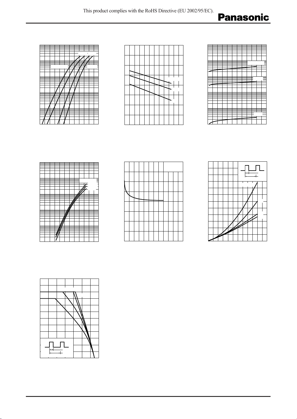
IF V
2
10
10
)
A
(
F
10
Forward current I
10
10
Ta = 150°C
1
−1
−2
−3
0 0.2 0.4 0.6 0.8 1.0 1.2
F
100°C 25°C
Forward voltage VF (V
IR T
2
10
10
)
mA
(
R
1
−1
10
Reverse current I
−2
10
−3
10
−40 0 40 80 120 160 200
a
VR = 200 V
Ambient temperature Ta (°C
−20°C
)
100 V
10 V
VF T
1.6
)
1.2
V
(
F
0.8
Forward voltage V
0.4
0
−40 0 40 80 120 160 200
a
Ambient temperature Ta (°C
Ct V
80
)
pF
60
(
t
40
20
Terminal capacitance C
R
f = 1 MHz
T
IF = 20 A
10 A
1 A
= 25°C
a
2
10
10
)
mA
(
R
1
−1
10
Reverse current I
−2
10
−3
10
0 40 80 120 160 200 240
)
60
)
W
(
50
D(AV)
40
30
20
10
IR V
R
Ta = 150°C
Reverse voltage VR (V
P
I
D(AV)
F(AV)
t0 / t1 = 1/6
100°C
25°C
)
1/3
1/2
DC
t
0
t
1
Power dissipation (Average) P
0
0 50 100 150 200 250 300
)
Reverse voltage VR (V
)
0
04812162024
Forward current (Average) I
F(AV)
(A
)
I
T
24
)
A
20
(
F(AV)
16
12
8
4
Forward current (Average) I
0
20 60 140100
F(AV)
1/3
1/6
Case temperature TC (°C
t0 / t1 = 1/2
t
0
t
1
C
DC
)
2
SKJ00004BED
 Loading...