

Panasonic MA2YJ50 User Manual
This product complies with the RoHS Directive (EU 2002/95/EC).
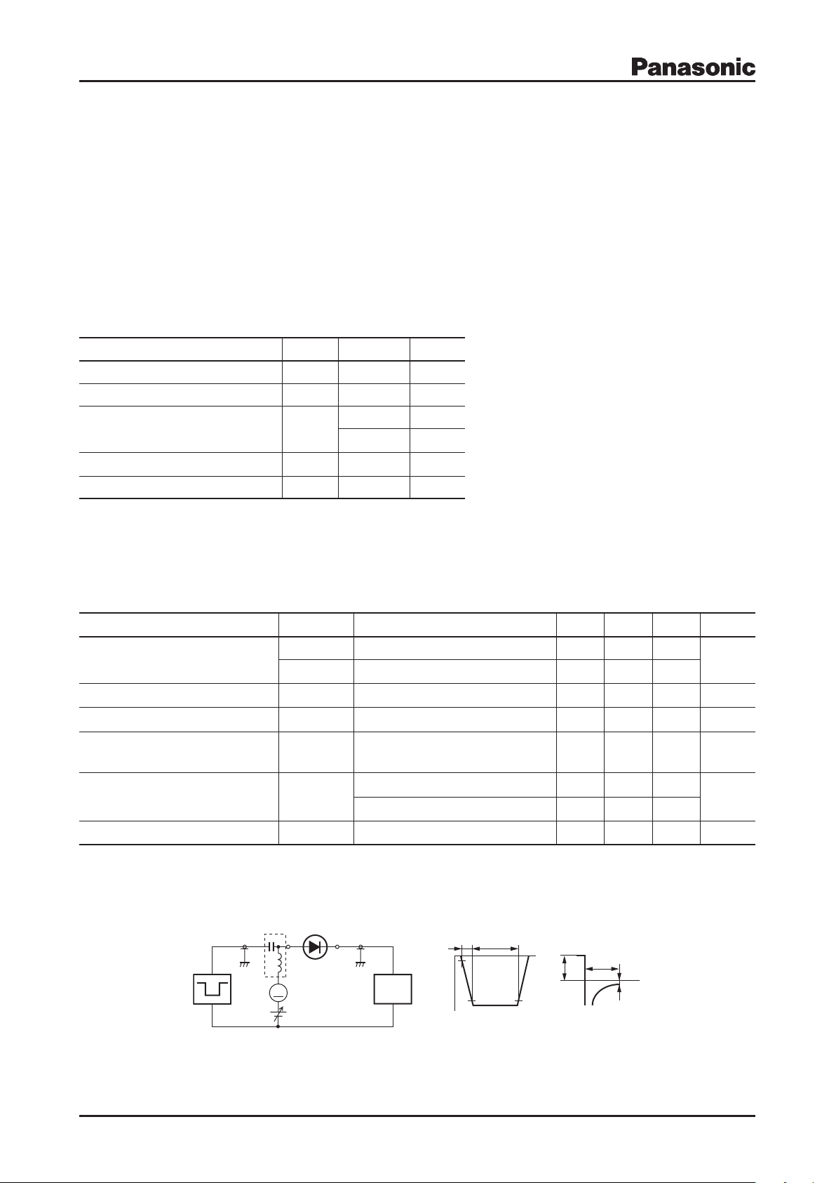
Bias Application Unit (N-50BU)
90%
Pulse Generator
(PG-10N)
Rs = 50 Ω
Wave Form Analyzer
(SAS-8130)
Ri = 50 Ω
tp = 2 µs
tr = 0.35 ns
δ = 0.05
IF = IR = 100 mA
RL = 100 Ω
10%
Input Pulse Output Pulse
I
rr
= 10 mA
t
r
t
p
t
rr
V
R
I
F
t
t
A
Schottky Barrier Diodes (SBD)
MA2YJ50
Silicon epitaxial planar type
For rectification
Features
Forward current (Average) I
Low forward voltage VF : 0.55 V (max.)
= 3.0 A rectification is possible.
F(AV)
Absolute Maximum Ratings Ta = 25°C
Parameter Symbol Rating Unit
Reverse voltage V
1
Forward current (Average)
*
Non-repetitive peak forward surge current
Junction temperature T
Storage temperature T
Note) *1: Lead temperature: Tl = 60°C, DC wave on
2: Rectangle wave 1 cycle (Pulse width = 50 ms, non-repetitive peak current)
*
3: 50 Hz sine wave 1 cycle (Non-repetitive peak current)
*
I
F(AV)
I
FSM
R
j
stg
40 V
3.0 A
*
50
*
15
150
–55 to +150
Electrical Characteristics Ta = 25°C±3°C
Parameter Symbol Conditions Min Typ Max Unit
Forward voltage
V
Reverse current I
Terminal capacitance C
V
Reverse recovery time
*
Thermal resistance (j-a) R
t
rr
th(j-a)
IF = 1.0 A 0.35 0.44
F1
IF = 3.0 A 0.47 0.55
F2
VR = 40 V 40 200
R
VR = 10 V, f = 1 MHz 70 pF
t
IF = IR = 100 mA, Irr = 10 mA,
RL = 100 W
Mounted on an alumina PC board 110
Mounted on a glass epoxy PC board 160
Package
Code
Mini2-F1
Pin Name
1: Anode
2: Cathode
Marking Symbol: 3D
2
3
A
A
°C
°C
V
mA
25 ns
°C/W
Thermal resistance (j-l) R
Note) 1. Measuring methods are based on JAPANESE INDUSTRIAL STANDARD JIS C 7031 measuring methods for diodes.
2. This product is sensitive to electric shock (static electricity, etc.). Due attention must be paid on the charge of a human body and the leakage
3. *: trr measurement circuit
Publication date: November 2008 SKH00238AED 1
of current from the operating equipment.
th(j-l)
60
°C/W
This product complies with the RoHS Directive (EU 2002/95/EC).
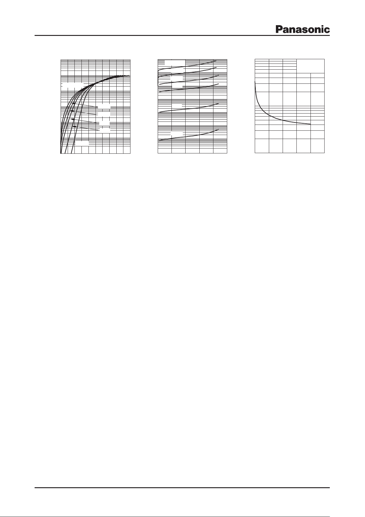
10
−4
10
−3
10
−2
0 0.2
0.4
0.6 0.8 1.0
10
−1
10
2
10
1
MA2YJ50_ IF-V
F
Forward current I
F
(A)
Forward voltage VF (V)
Ta = 150°C
125°C
25°C
100°C
−25°C
75°C
0 10 20 4030 50
Reverse voltage VR (V)
Reverse current I
R
(mA)
10
−5
10
−3
10
−4
10
−2
10
−1
1
10
2
10
MA2YJ50_IR-VR
T
a
= 150°C
75°C
125°C
100°C
25°C
−20°C
10
10
2
10
3
0 10 20 30 40 50
Reverse voltage VR (V)
Terminal capacitance C
t
(pF)
MA2YJ50_Ct-VR
T
a
= 25°C
f = 1 MHz
MA2YJ50
IF VF IR VR Ct V
R
2 SKH00238AED
 Loading...