

Panasonic MA2B190 Datasheet
Switching Diodes
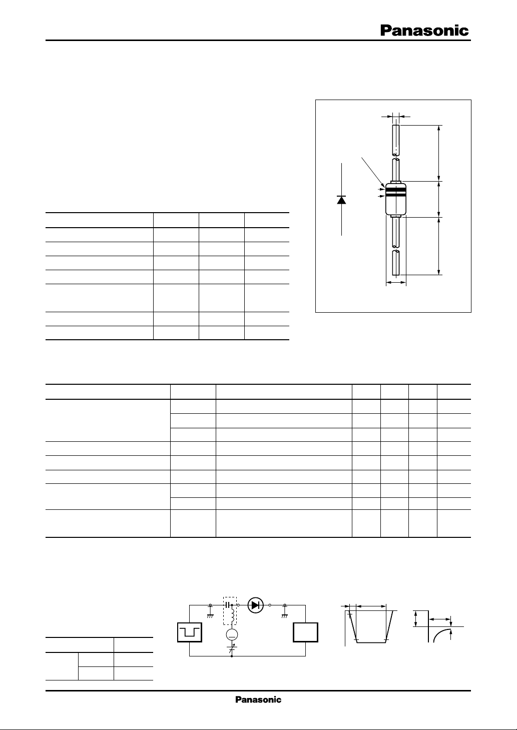
24 min.4.5 max.24 min.
φ 0.56 max.
φ 1.95 max.
COLORED BAND
INDICATES
CATHODE
1st Band
2nd Band
1
2
MA2B190
Silicon epitaxial planar type
For switching circuits
■ Features
•
Low forward dynamic resistance r
•
Small terminal capacitance, C
■ Absolute Maximum Ratings Ta = 25°C
Parameter Symbol Rating Unit
Reverse voltage (DC) V
Repetitive peak reverse voltage V
Average forward current I
Repetitive peak forward current
Non-repetitive peak forward I
surge current
Junction temperature T
Storage temperature T
Note) * : t = 1 s
*
f
t
R
RRM
F(AV)
I
FRM
FSM
j
stg
100 mA
225 mA
500 mA
200 °C
−55 to +200 °C
Unit : mm
35 V
35 V
1: Cathode
2: Anode
JEDEC: DO-35
■ Electrical Characteristics Ta = 25°C
Parameter Symbol Conditions Min Typ Max Unit
Reverse current (DC) I
R1
I
R2
I
R3
Forward voltage (DC) V
Reverse voltage (DC) V
Terminal capacitance C
Forward dynamic resistance r
3
Reverse recovery time
Note) 1. Rated input/output frequency: 2.5 MHz
2. *1:rf measuring instrument: Nihon Koshuha Model TDC-121A
*2:rf measuring instrument: YHP 4191A RF IMPEDANCE ANALYZER
*
*
f
*
r
f
t
rr
*3 :trr measuring circuit
■ Cathode Indication
Type No. MA2B190
Color 1st Band White
2nd Band White
Pulse Generator
(PG-10N)
R
s
VR = 15 V 0.005 µA
VR = 30 V 0.01 µA
VR = 35 V, Ta = 150°C 100 µA
IF = 100 mA 1.2 V
F
IR = 100 µA35V
R
VR = 0 V, f = 1 MHz 4 pF
t
1
IF = 3 mA, f = 30 MH
2
IF = 3 mA, f = 30 MH
IF = 10 mA, VR = 1 V 0.2 ms
Irr = 0.1 · IR, RL = 100 Ω
Bias Application Unit N-50BU
A
= 50 Ω
W.F.Analyzer
(SAS-8130)
= 50 Ω
R
i
t
2.5 Ω
3.6 Ω
I
F
= 10 mA
I
F
= 1 V
V
R
= 100 Ω
R
L
t
rr
I
= 0.1 · I
rr
t
R
Z
Z
Input Pulse Output Pulse
t
t
p
r
10%
90%
V
R
= 2 µs
t
p
= 0.35 ns
t
r
δ = 0.05
1
MA2B190
Switching Diodes
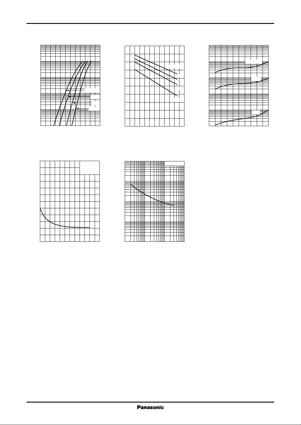
IF V
3
10
2
10
)
mA
(
F
10
1
Forward current I
−1
10
−2
10
0 0.2 0.4 0.6 0.8 1.0 1.2
F
Forward voltage VF (V
V
6
5
)
pF
(
t
4
3
R
Ta = 150°C
100°C
25°C
− 20°C
)
f = 1 MHz
= 25°C
T
a
VF T
1.0
0.8
)
V
(
F
0.6
0.4
Forward voltage V
0.2
0
−40 0 40 80 120 160
a
Ambient temperature Ta (°C
rf I
100
)
Ω
(
f
10
1
F Ct
f = 30 MHz
IF = 10 mA
3 mA
1 mA
0.1 mA
IR V
3
10
2
10
)
nA
(
R
10
1
Reverse current I
−1
10
−2
10
0 1020304050
)
Reverse voltage VR (V
R
Ta = 150°C
100°C
25°C
)
2
Terminal capacitance C
1
0
0 102030405060
Reverse voltage VR (V
0.1
Forward dynamic resistance r
0.01
0.1
)
1100.3 3 30 100
Forward current IF (mA
)
2
 Loading...