

Panasonic Lumix DMC-LS5PU, Lumix DMC-LS5E, Lumix DMC-LS5EE, Lumix DMC-LS5GC, Lumix DMC-LS5GF Service Manual
...
© Panasonic Corporation 2011 Unauthorized copying and distribution is a violation of law.
ORDER NO. DSC1108045CE
B26
Digital Camera
Model No. DMC-LS5PU
DMC-LS5E
DMC-LS5EE
DMC-LS5GC
DMC-LS5GF
DMC-LS5GN
DMC-LS5GW
Colour
(S)...........Silver Type
(K)...........Black Type
(P)...........Pink Type

2
TABLE OF CONTENTS
PAGE PAGE
1 Safety Precautions -----------------------------------------------3
1.1. General Guidelines ----------------------------------------3
1.2. Leakage Current Cold Check ---------------------------3
1.3. Leakage Current Hot Check (See Figure 1.)--------3
1.4. How to Discharge the E.Capacitor on the
Frame Unit KIT----------------------------------------------4
2Warning--------------------------------------------------------------5
2.1. Prevention of Electrostatic Discharge (ESD)
to Electrostatically Sensitive (ES) Devices ----------5
3 Service Navigation------------------------------------------------6
3.1. Introduction --------------------------------------------------6
3.2. General Description About Lead Free Solder
(PbF) ----------------------------------------------------------6
3.3. Important Notice--------------------------------------------6
3.4. How to Define the Model Suffix (NTSC or PAL
model)---------------------------------------------------------7
4 Specifications----------------------------------------------------10
5 Location of Controls and Components------------------11
6 Service Fixture & Tools---------------------------------------13
6.1. Service Fixture and Tools ------------------------------13
7 Disassembly and Assembly Instructions---------------14
7.1. Disassembly Flow Chart--------------------------------14
7.2. PCB Location----------------------------------------------14
7.3. Disassembly Procedure--------------------------------15
8 Measurements and Adjustments --------------------------21
8.1. Introduction ------------------------------------------------21
8.2. Matrix chart (Replaced part and Adjustment
item) ---------------------------------------------------------21
8.3. Adjustment procedures---------------------------------22
9 Maintenance ------------------------------------------------------28
9.1. Cleaning Lens and LCD Panel -----------------------28
10 Interconnection Diagram -------------------------------------29
3
1 Safety Precautions
1.1. General Guidelines
1. IMPORTANT SAFETY NOTICE
There are special components used in this equipment
which are important for safety. These part s are marked by
in the Schematic Diagrams, Circuit Board Layout,
Exploded Views and Replacement Parts List. It is essential that these critical parts should be replaced with manufacturer’s specified parts to prevent X-RADIATION,
shock, fire, or other hazards. Do not modify the original
design without permission of manufacturer.
2. An Isolation Transformer should always be used during
the servicing of AC Adaptor whose chassis is not isolated
from the AC power line. Use a transformer of adequate
power rating as this protects the technician from accidents resulting in personal injury from electrical shocks. It
will also protect AC Adaptor from being damaged by accidental shorting that may occur during servicing.
3. When servicing, observe the original lead dress. If a short
circuit is found, replace all parts which have been overheated or damaged by the short circuit.
4. After servicing, see to it that all the protective devices
such as insulation barriers, insulation papers shields are
properly installed.
5. After servicing, make the following leakage current
checks to prevent the customer from being exposed to
shock hazards.
1.2. Leakage Current Cold Check
1. Unplug the AC cord and connect a jumper between the
two prongs on the plug.
2. Measure the resistance value, with an ohmmeter,
between the jumpered AC plug and each exposed metallic cabinet part on the equipment such as screwheads,
connectors, control shafts, etc. When the exposed metallic part has a return path to the chassis, the reading
should be between 1 MΩ and 5.2 MΩ. When the exposed
metal does not have a return path to the chassis, the
reading must be infinity.
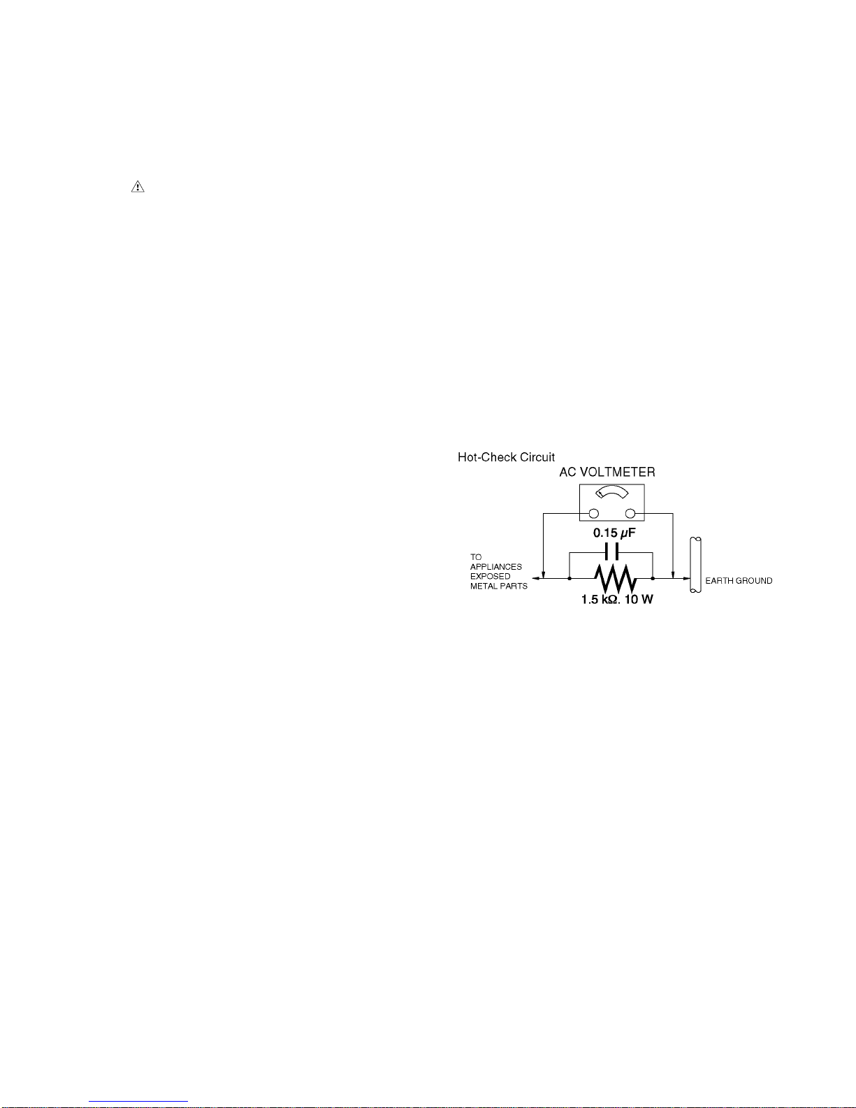
1.3. Leakage Current Hot Check
(See Figure 1.)
1. Plug the AC cord directly into the AC outlet. Do not use
an isolation transformer for this check.
2. Connect a 1.5 kΩ, 10 W resistor, in parallel with a 0.15 μF
capacitor, between each exposed metallic part on the set
and a good earth ground, as shown in Figure 1.
3. Use an AC voltmeter, with 1 kΩ/V or more sensitivity, to
measure the potential across the resistor.
4. Check each exposed metallic part, and measure the voltage at each point.
5. Reverse the AC plug in the AC outlet and repeat each of
the above measurements.
6. The potential at any point should not exceed 0.75 V RMS.
A leakage current tester (Simpson Model 229 or equivalent) may be used to make the hot checks, leakage current must not exceed 1/2 mA. In case a measurement is
outside of the limits specified, there is a possibility of a
shock hazard, and the equipment should be repaired and
rechecked before it is returned to the customer.
Figure. 1
4
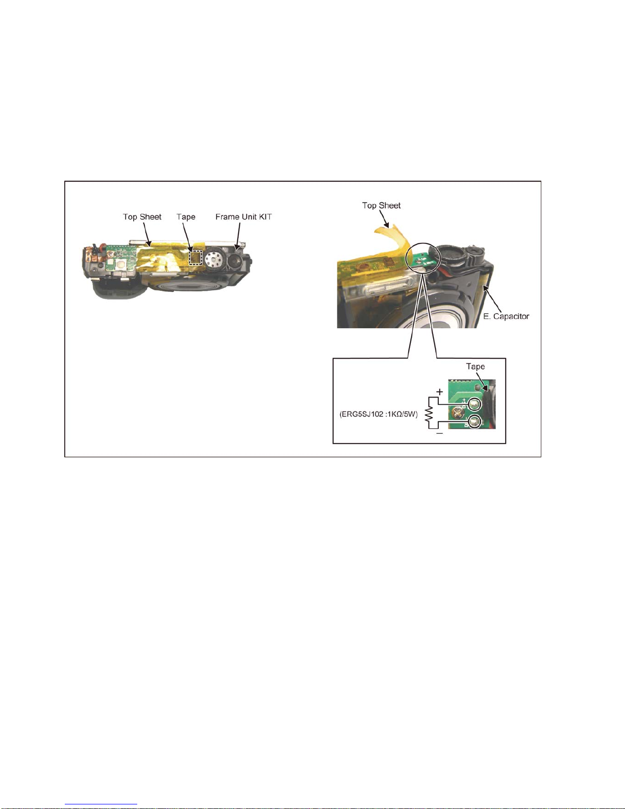
1.4. How to Discharge the E.Capacitor on the Frame Unit KIT
CAUTION:
1. Make sure to discharge the E.capacitor on the Frame Unit KIT.
2. Be careful of the high voltage circuit on the Frame Unit KIT when servicing.
[Discharging Procedure]
1. Refer to the disassemble procedure and remove the necessary parts/unit.
2. Install the insulation tube onto the lead part of resistor (ERG5SJ102:1kΩ /5W).
(an equivalent type of resistor may be used.)
3. Place a resistor between both terminals of E.capacitor on the Frame Unit KIT for approx. 5 seconds.
4. After discharging, confirm that the E.capacitor voltage is lower than 10V using a voltmeter.
Fig. F1

5
2Warning
2.1. Prevention of Electrostatic Discharge (ESD) to Electrostatically
Sensitive (ES) Devices
Some semiconductor (solid state) devices can be damaged easily by static electricity. Such components commonly are called Electrostatically Sensitive (ES) Devices.
The following techniques should be used to help reduce the incidence of compon ent damage caused by electrostatic discharge
(ESD).
1. Immediately before handling any semiconductor component or semiconductor-equipped assembly, drain off any ESD on your
body by touching a known earth ground. Alternatively, obtain and wear a commercially available discharging ESD wrist strap,
which should be removed for potential shock reasons prior to applying power to the unit under test.
2. After removing an electrical assembly equipped with ES devices, place the assembly on a conductive surface such as al uminum foil, to prevent electrostatic charge buildup or exposure of the assembly.
3. Use only a grounded-tip soldering iron to solder or unsolder ES devices.
4. Use only an antistatic solder removal device. Some solder removal devices not classified as "antistatic (ESD protected)" can
generate electrical charge sufficient to damage ES devices.
5. Do not use freon-propelled chemicals. These can generate electrical charges sufficient to damage ES devices.
6. Do not remove a replacement ES device from its protective package until immediately before you are ready to install it. (Most
replacement ES devices are packaged with leads electrically shorted together by conductive foam, aluminum foil or comparable conductive material).
7. Immediately before removing the protective material from the leads of a replacement ES device, touch the protective material
to the chassis or circuit assembly into which the device will be installed.
CAUTION :
Be sure no power is applied to the chassis or circuit, and observe all other safety precautions.
8. Minimize bodily motions when handling unpackaged replacement ES devices. (Otherwise harmless motion such as the
brushing together of your clothes fabric or the lifting of your foot from a carpeted floor can generate static electricity (ESD) suf-
ficient to damage an ES device).
6
3 Service Navigation
3.1. Introduction
This service manual contains technical information, which allow service personnel’s to understand and service this model.
Please place orders using the parts list and not the drawing reference numbers.
If the circuit is changed or modified, the information will be followed by service manual to be controlled with original service manual.
3.2. General Description About Lead Free Solder (PbF)
The lead free solder has been used in the mounting process of all electrical compone nts on the printed circuit bo ards used for this
equipment in considering the globally environmental conservation.
The normal solder is the alloy of tin (Sn) and lead (Pb). On the other hand, the lead free solder is the alloy mainly consists of tin
(Sn), silver (Ag) and Copper (Cu), and the melting point of the lead free solder is higher approx.30°C (86°F) mo re than th at of the
normal solder.
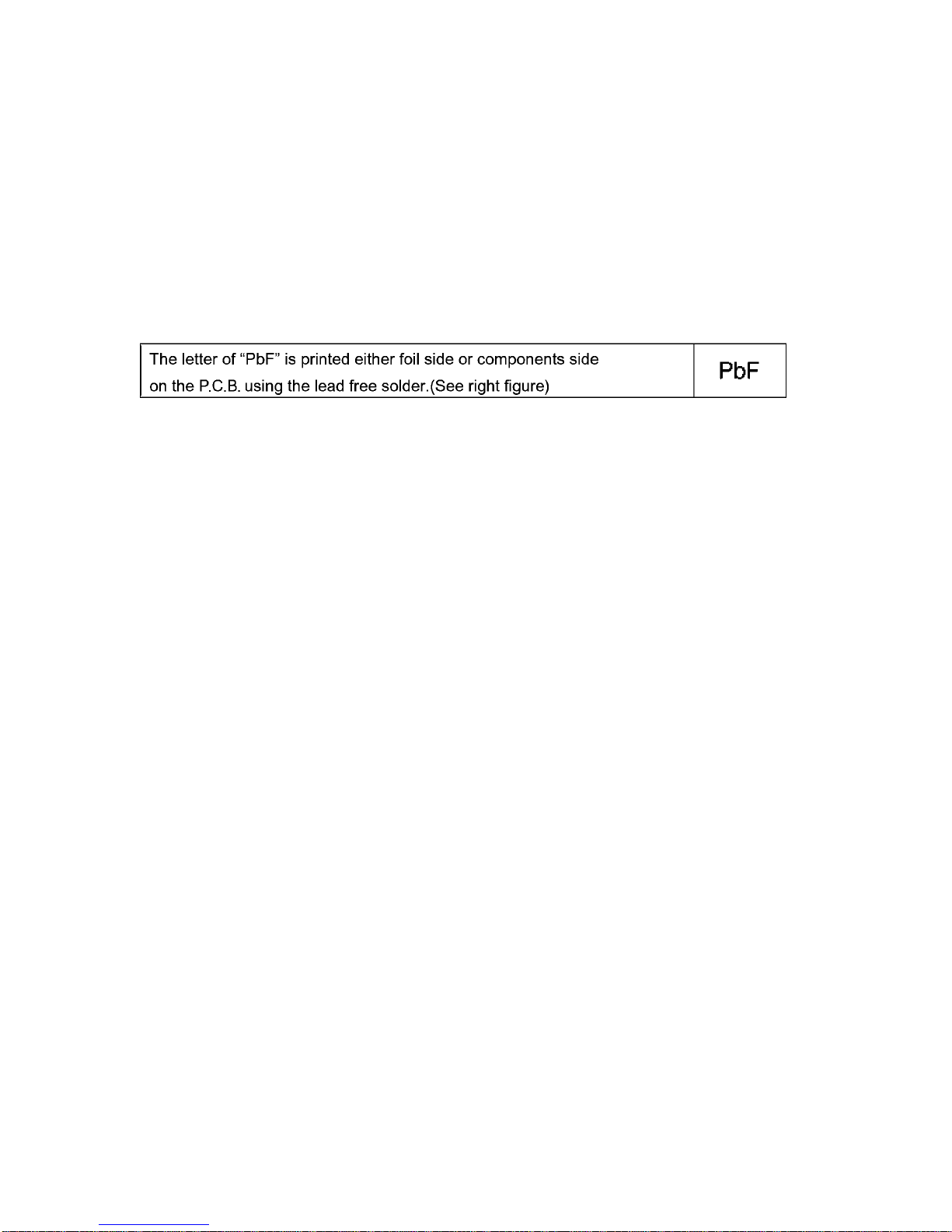
Distinction of P.C.B. Lead Free Solder being used
Service caution for repair work using Lead Free Solder (PbF)
• The lead free solder has to be used when repairing the equipment for which the lead free solder is used.
(Definition: The letter of “PbF” is printed on the P.C.B. using the lead free solder.)
• To put lead free solder, it should be well molten and mixed with the original lead free solder.
• Remove the remaining lead free solder on the P.C.B. cleanly for solderin g of the new IC.
• Since the melting point of the lead free solder is high er than that of the normal lead solder, it takes the longer time to melt the
lead free solder.
• Use the soldering iron (more than 70W) equipped with the temperature control after setting the temperature at 350±30°C
(662±86°F).
Recommended Lead Free Solder (Service Parts Route.)
• The following 3 types of lead free solder are available through the service parts route.
RFKZ03D01KS-----------(0.3mm 100g Reel)
RFKZ06D01KS-----------(0.6mm 100g Reel)
RFKZ10D01KS-----------(1.0mm 100g Reel)
Note
* Ingredient: tin (Sn) 96.5%, silver (Ag) 3.0%, Copper (Cu) 0.5%, Cobalt (Co) / Germanium (Ge) 0.1 to 0.3%
3.3. Important Notice
The following parts are handled as the smallest replacement parts for this unit.
Therefore if any components on them are defective, replace whole parts as a unit.
FRAME UNIT KIT (including TOP P.C.B.)
LENS UNIT (W/CCD)
MAIN P.C.B.
7
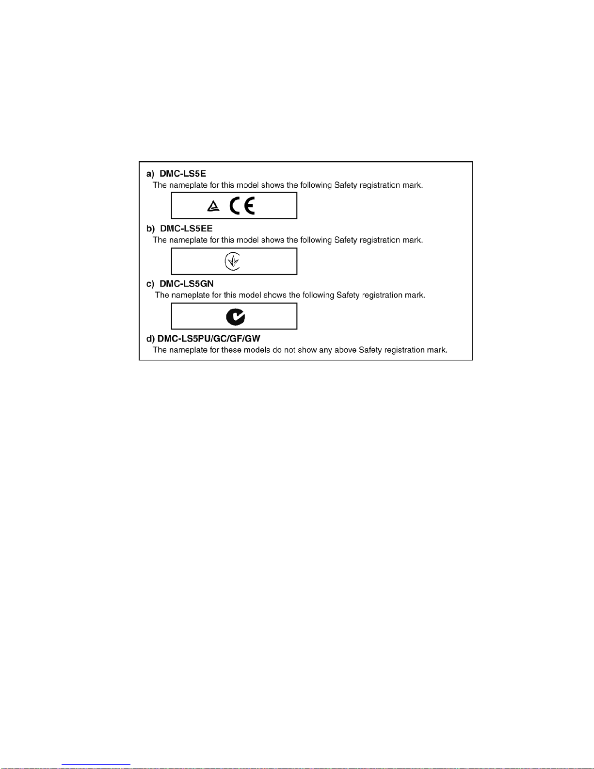
3.4. How to Define the Model Suffix (NTSC or PAL model)
There are four kinds of DMC-LS5, regardless of the colours.
• a) DMC-LS5E
• b) DMC-LS5EE
• c) DMC-LS5GN
• d) DMC-LS5PU/GC/GF/GW
What is the difference is that the “INITIAL SETTINGS” data which is stored in Flash-ROM mounted on MAIN P.C.B..
3.4.1. Defining methods:
To define the model suffix to be serviced, refer to the nameplate which is putted on the bottom side of the Unit.
NOTE:
After replacing the MAIN P.C.B., make sure to perform the “firmware version up”, “Initial settings” and “adjustment”.
The firmware & adjustment software is available at “software download” on the “Support Informatio n from NWBG/VDBG-AVC”
web-site in “TSN system”.
8
3.4.2. INITIAL SETTINGS:
After replacing the MAIN P.C.B., make sure to perform the initial settings after achieving the adjustment by ordering the following
procedure in accordance with model suffix of the unit.
1. PROCEDURES:
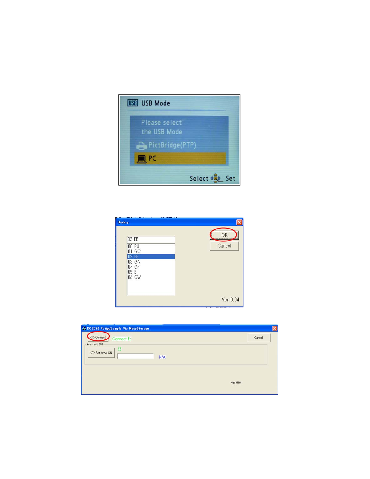
Step 1. Setup:
a. Attach the Battery to the unit.
b. Connect the Camera unit and a PC with a USB cable.
c. Turn the power switch to ON.
d. Select the USB mode to “PC” mode, then press the "MENU/SET" button.
Step 2.Execute the Initial Setting:
a. Execute the PC software “PcAppSample.exe”.
b. Select Sales Area and click “OK”.
c. Click the “Connect”, then Model name is displayed.
9
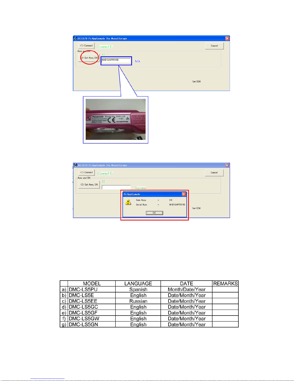
d. Input the Serial Number by 12 digits
* To make it to 12 digits, put the character of “%” in the head.
e. Click the “Set Area S/N”, then “OK” window is displayed.
NOTE:
If the Initial Setting is executing, the setting item of DSC returns to the state of the shipment.
Step 3.Confirmation :
a. Close the “PcAppSample.exe” by clicking on the “Cancel” located on the top right corner.
b. Turn off the camera switch.
c. Disconnect the USB cable.
d. Confirm that the language and Clock set request screen is displayed on the LCD monitor. Major default setting condition is as
shown in the following table.
10
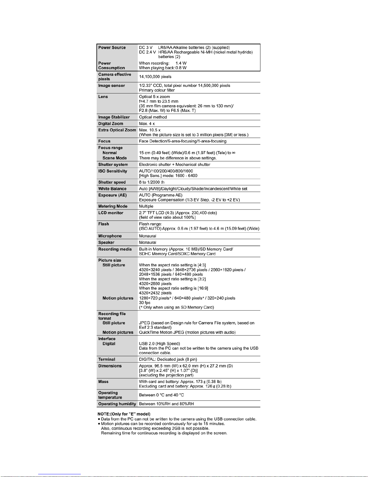
4 Specifications
11
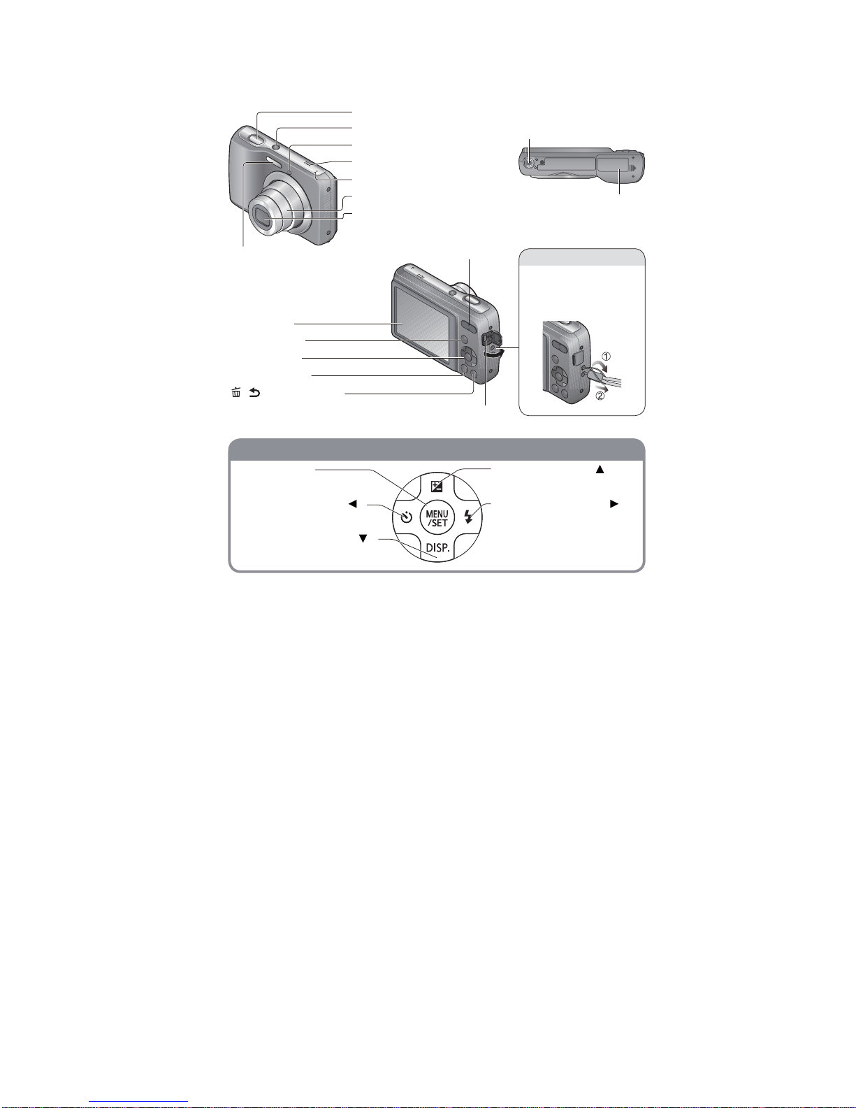
5 Location of Controls and Components
nottubrosruC
Tripod receptacle
Ensure that the tripod is
stable.
Card/Battery door
Shutter button
Power button
Self-timer indicator
Speaker
Microphone
Lens barrel
Lens
LCD monitor
[MODE] button
Cursor button
Playback button
[
/ ] (Delete/Return)
button
Zoom button Flash
Hand strap eyelet
We recommend using
the supplied hand strap
to avoid dropping the
camera.
[DIGITAL]socket
[MENU/SET]
(menu display/set)
Left cursor button ( )
Self-timer
Down cursor button ( )
Changing information display
Up cursor button ( )
Exposure Compensation
Right cursor button ( )
Flash
Ɣ
The illustrations and screens in this manual may differ from the actual product.
Ɣ
Some methods of holding the camera may block the speaker, making it difficult to hear
the beep, etc.
 Loading...