

Panasonic LP-GS052, LP-GS051, LP-GS051-F, LP-GS051-L, LP-GS051-LF Serial Communication Command Manual
...
Laser Marker
Serial Communication
Command Guide
LP-400/V compatible mode
LP-GS series
LP-RC series
LP-RF series
LP-RV series
ME-LP-GS-SR-COMP-3
2019. 4
panasonic.net/id/pidsx/global

Preface
ME-LP-GS-SR-COMP-3
Thank you for purchasing our product.
For full use of this product safely and properly, please read this document carefully.
This product has been strictly checked and tested prior to its delivery. However, please make sure that this product
operates properly before using it. In case that the product becomes damaged or does not operate as specified in this
document, contact the dealer you purchased from or our sales office.
General terms and conditions of this document
⿎
1. Before using this product, or before every starting operation, please confirm the correct functioning and performance
of this product.
2. Contents of this document could be changed without notice.
3. This document must not be partially or totally copied or revised.
4. All efforts have been made to ensure the accuracy of all information in this document. If there are any questions,
mistakes, or comments in this document, please notify us.
5. Please remind that we assume no liability for any results arising out of operations regardless of the above clauses.
Disclaimer
⿎
The applications described in this document are all intended for examples only. The purchase of our products described in
this document shall not be regarded as granting of a license to use our products in the described applications. We do NOT
warrant that we have obtained some intellectual properties, such as patent rights, with respect to such applications, or that
the described application may not infringe any intellectual property rights, such as patent rights, of a third party.
Trademark
⿎
• Windows is a registered trademark or trademark of Microsoft Corporation in the United States and/or other countries.
• QR Code is a registered trademarks of DENSO WAVE INCORPORATED.
• Adobe, Adobe Logo, Adobe Reader, and Adobe Illustrator are either registered trademarks or trademarks of Adobe
Systems Incorporated in the United States and/or other countries.
• Bluetooth is a registered trademark of U.S.A. Bluetooth SIG Inc.
• All other product names and companies provided in this document are trademarks or registered trademarks of their
respective companies.
2
DANGER
WARNING
CAUTION
DANGER
ALWAYS FOLLOW THESE IMPORTANT
ME-LP-GS-SR-COMP-3
Cautions in Handling
To reduce the risk of injury, loss of life, electric shock, fire, malfunction, and damage to equipment or property, always
observe the following safety precautions.
The following symbols are used to classify and describe the level of hazard, injury, and property damage caused when the
denotation is disregarded and improper use is performed.
Denotes a potential hazard that will result in serious injury or death.
Denotes a potential hazard that could result in serious injury or death.
Denotes a hazard that could result in minor injury.
The following symbols are used to classify and describe the type of instructions to be observed.
This symbol is used to alert users to a specific operating procedure that must not be performed.
This symbols is used to alert users to a specific operating procedure that must be followed in order to
operate the unit safely.
SAFETY PRECAUTIONS!
This symbols is used to alert users to a specific operating procedure that must be performed carefully.
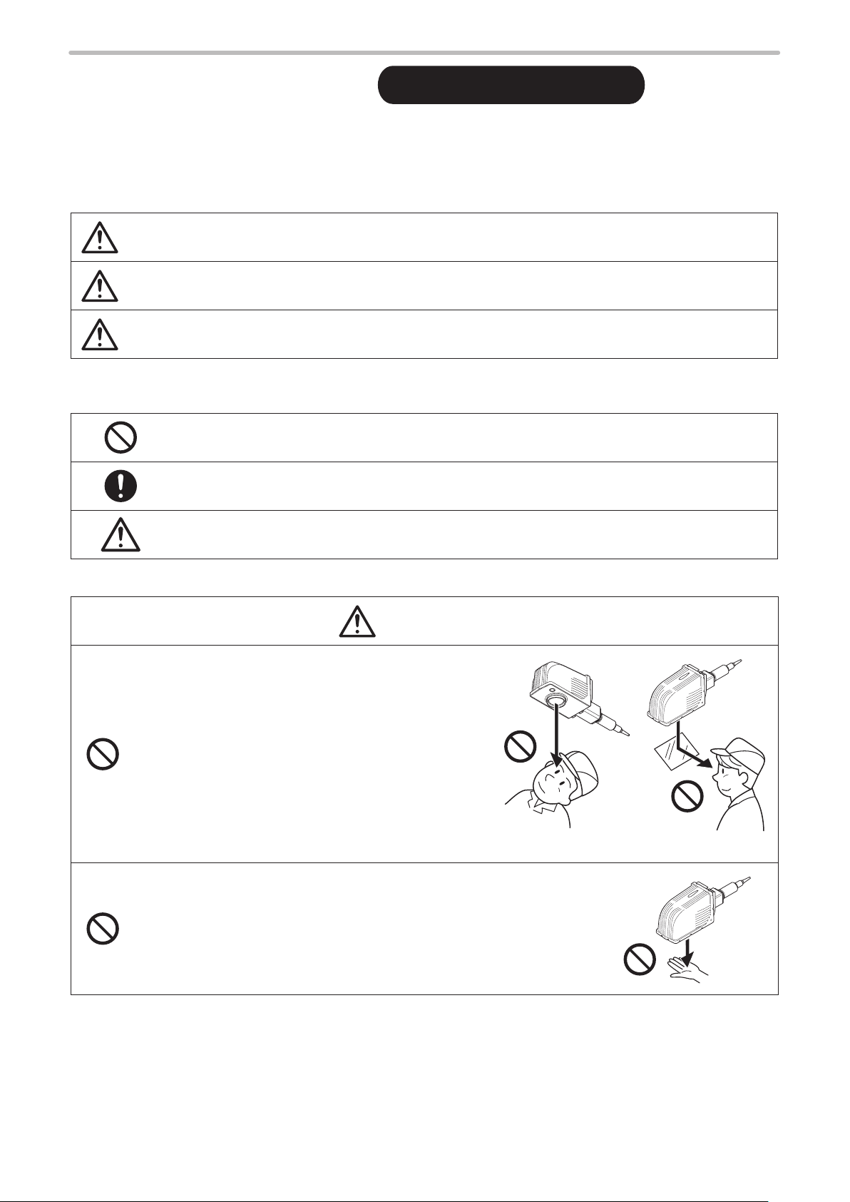
• Never look at laser beam directly, through lens or
through any other optical components. Laser beam
radiation into the eye causes blindness or serious
damage to the eye.
Not only the direct beam of laser, but also diffused
reflected beam is harmful.
• Never touch laser beam and avoid human skin, clothing and any other
flammable object from laser beam exposure directly.
Burning into deep skin might result and there is a risk of fire.
3
WARNING
• Do not use this product anywhere where fire is strictly prohibited, near inflammable gas, objects or organic
ME-LP-GS-SR-COMP-3
solvents such as thinner or gasoline, or in dusty place. There is a risk of fire.
• Do not use this product except for water-resistant part in wet place. In addition, never conduct wiring or
maintenance work with wet hands or when the product surface is wet. Otherwise, electric shock and/or
malfunction may result.
• Never disassemble the product.
Doing so may cause exposure to the laser beam or electric shock.
• Do not insert hands or objects between the gaps of the exhaust port or intake port. There is a risk of
electrical shock or injury.
• Take laser protection measures required to use Class 4 laser products subject to the local laws and
regulations of the country or region in which this laser product is used.
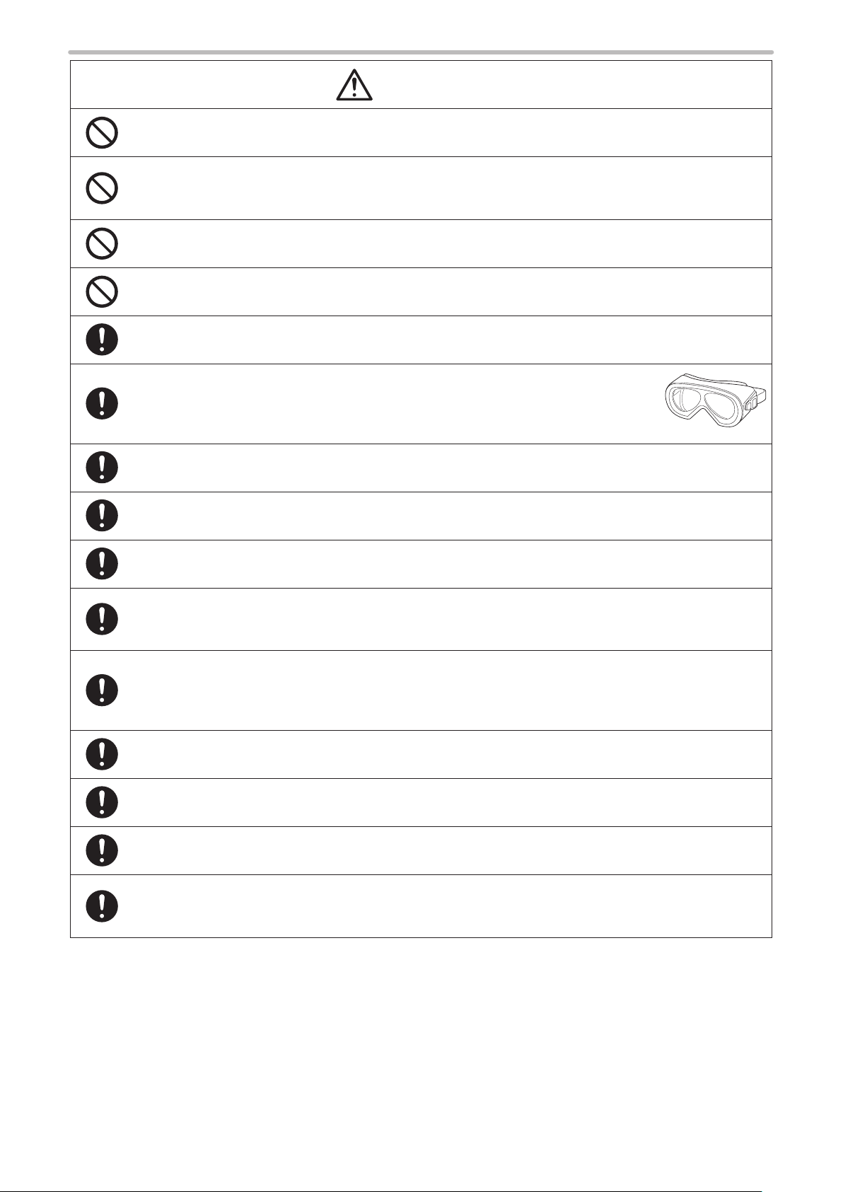
• To protect the operators' eyes, make it mandatory to wear goggles against laser beam
within the laser controlled area. The protective goggles can momentarily protect the
eyes against the scattered beam. Never look at the direct beam or reflected beam
even when you are wearing the protective goggles.
• Set protective enclosure with proper reflectance, durability and thermal resistance to enclose the laser
radiation area without leakage.
• Construct an interlock systems such as a function to stop laser radiation for the maintenance door of the
protective enclosure.
• After power supply of laser marker is turned off, laser safety manager must remove the key and keep it.
• Be sure to connect the head and controller (for LP-RV series, the head, controller and oscillator unit) of the
laser marker which have the same model number. Otherwise there is a risk of exposure to laser radiation
or failure.
• Read all packaged guides and manuals thoroughly, and do not operate, install and connect the laser
marker with any other methods except the instructions provided in the manuals. If the product is used in a
manner not specified by the instruction, the safety protection and functions provided by the device may be
impaired and may cause injury, electrical shock or exposure of laser beam.
• Prior to wiring, cable connecting, and/or maintenance work, ensure that all the power switches are turned
off. Otherwise, electrical shock may result.
• The wiring and maintenance must be conducted by the electrical engineers or under their supervision.
Incorrect work may cause electrical shock.
• Connect ground wire before using. A failure or electrical leakage that occurs when the unit is not properly
grounded may result in electric shock.
• For LP-RF/LP-RV series, be careful neither to give strong power to the fiber cable nor to nip it for
installation. Do not install the product to the systems that give excessive load acts on the fiber cable, such
as head movement unit. If the fiber cable is damaged, it may cause laser exposures.
4
WARNING
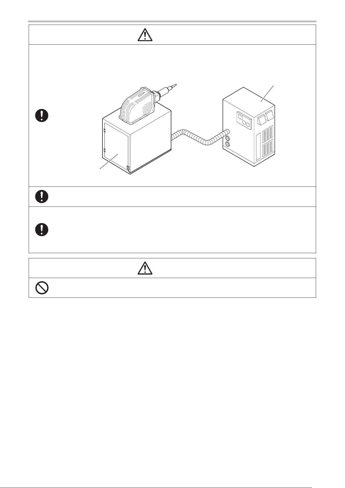
• Remove the dust and/or gas which may be generated during the laser radiation with dust collector or
CAUTION
ME-LP-GS-SR-COMP-3
exhauster. Use an appropriate dust collector or exhauster for dust or gas generated.
Depending on the material of the objects, harmful dust and/or gas to the human body and the laser marker
may be generated.
Dust collector
Protective
• When using the assist gas for laser processing, take safety precautions to protect operators from
• To carry this product, wear the non-slip gloves and safety shoes. Hold the product with both hands. Do not
• For LP-RC/LP-RF/LP-RV series, carry the controller unit with two persons. Lifting or carrying without
• Install this product in the stable place without vibration and shock.
• In case it falls down, it may cause injury.
enclosure
exposure, ignition, toxic effect, excess or lack of oxygen.
hold the cables or connectors at carrying.
assistance may cause of injury.
• Do not touch the head surface of LP-RF/LP-RV series during and right after the operation. It becomes hot
and may cause burn injury.
5

How to Read this Document
ME-LP-GS-SR-COMP-3
Symbol description
ワㄐㄕㄊㄆ
ンㄆㄇㄆㄓㄆㄏㄆ
Target model
This manual is subject to the following Laser Marker models.
In this manual, this product is called “laser marker”.
If the setting contents or specifications vary by models, the target models are specified in the text.
In the text, multiple models may be described collectively, as shown in the table below.
Please remind that the illustration and the screen image may vary with the model.
Target model Description in the text
LP-GS0 51 LP-GS0 51- E LP-GS0 51 LP-GS0 51(-L) LP-GS series
LP-GS0 51- F LP-GS0 51- FE LP-GS0 51- F N
LP-GS0 51- L LP- G S051- LE LP-GS0 51- L
LP-GS0 51- L F LP-GS0 51- L FE LP-GS0 51- L FN
LP-GS052 LP-GS052-E LP-GS052
LP-GS052-F LP-GS052-FE LP-GS052-FN
LP-RC350S LP-RC350S LP-RC series
“Notice” denotes any instructions or precautions for using this product. To prevent the damage or
malfunction of the product, observe these precautions fully.
“Reference” denotes any hints for operation, detail explanations, or references.
LP-RF200P LP-RF200P LP-RF series
LP-RV200P LP-RV200P LP-RV series
6

Type of manuals
ME-LP-GS-SR-COMP-3
For this product, the following manuals are prepared. Read each manuals and operate this product correctly and safely.
Also, save the manuals for future use.
Laser Safety Guide
This manual describes the items required for using this product correctly and safely. All users shall be required for reading this manual.
Setup/Maintenance Guide
This manual describes the items required for introduction and installation of this product as well as for the maintenance
work.
• Product specifications, external dimensions
• Installation and connection method
• Signal details, I/O rating, and timing chart when I/O is used for control
• Maintenance details
Laser Marker NAVI smart Operation Manual
Instruction manual for the laser marker configuration software “Laser Marker NAVI smart”. This manual describes the
procedure and method to operate the laser marker, and the screen operations to set marking contents.
Mainly the users that operate this laser marker for actual marking procedure shall be required for reading this manual.
Serial Communication Command Guide
This manual describes the communication commands to control this product externally using the serial communication
(RS-232C/Ethernet). It describes the communication settings, communication data formats, communication commands,
and the control samples.
Mainly the machine builder and system integrator shall be required for reading this manual.
Serial Communication Command Guide: LP-400/V compatible mode
This manual describes the communication commands to control this product externally using the compatible command
format with the previous models of LP-400/LP-V series.
Mainly the machine builder and system integrator shall be required for reading this manual.
ンㄆㄇㄆㄓㄆㄏㄆ
• The PDF data of each manual is included on an attached CD-ROM “Laser Marker Smart Utility”.
• To read the PDF manual, Adobe Reader (Version X or later) of Adobe Systems Incorporated is required.
7

Contents
ME-LP-GS-SR-COMP-3
Preface ............................................................................................................... 2
Cautions in Handling
How to Read this Document
........................................................................................... 3
............................................................................... 6
1 Preparation of Command Control ………………………………… 11
1-1 Operation by External Devices ................................................................... 12
1-1-1 Operation method using external control device ........................................ 12
1-1-2 Operation procedure with external control ................................................. 13
1-1-3 Settings before external control ................................................................. 14
1-1-4 Remote mode settings ............................................................................... 17
1-2 Serial Communication Interfaces ................................................................ 18
1-3 RS-232C ..................................................................................................... 19
1-3-1 Interface specifications and connection .................................................... 19
1-3-2 Communication settings (LP-400/V compatible mode) ............................. 21
1-4 Ethernet ...................................................................................................... 22
1-4-1 Port specifications and connection ............................................................ 22
1-4-2 Communication settings ............................................................................ 23
1-4-3 Connecting to external control devices and its setting sample ................. 24
1-5 Checking the communication commands ................................................... 25
2 Communication Control Basics …………………………………… 26
2-1 Communication Data Types ........................................................................ 27
2-1-1 Request data .............................................................................................. 27
2-1-2 Response data ........................................................................................... 27
2-2 Communication Sequence .......................................................................... 28
2-3 Communication Data Format ...................................................................... 31
2-3-1 Basic data format ....................................................................................... 31
2-3-2 Request data ............................................................................................. 32
2-3-3 Response data .......................................................................................... 33
2-3-4 Character input method ............................................................................. 36
2-3-5 Character data input method ..................................................................... 37
2-4 Command Reception Condition .................................................................. 42
2-4-1 Commands requiring pre-set ..................................................................... 42
2-4-2 Command reception permission ............................................................... 42
2-4-3 Commands acceptable only with the shutter closed ................................. 43
2-4-4 Commands acceptable during alarm/warning occurrence ........................ 43
8
2-5 Communication Check................................................................................ 44
2-6 Control Sample ........................................................................................... 45

3 Data Format for Each Command ………………………………… 50
ME-LP-GS-SR-COMP-3
3-1 Command List ............................................................................................. 51
3-2 Command Description Details .................................................................... 55
3-3 Operation Control Commands .................................................................... 56
3-3-1 Command reception permission: MKM ..................................................... 56
3-3-2 Laser pumping: LSR .................................................................................. 57
3-3-3 Shutter open/close: SHT ........................................................................... 58
3-3-4 Marking trigger: MRK ................................................................................ 59
3-3-5 Trigger delay: DLY ..................................................................................... 60
3-3-6 Guide laser: GID ....................................................................................... 61
3-3-7 Status checking: STS ................................................................................ 62
3-3-8 Marking end verification: MST .................................................................. 63
3-4 File Setting Commands .............................................................................. 65
3-4-1 File selection by number: FNO .................................................................. 65
3-4-2 File selection by name: FNN ..................................................................... 66
3-4-3 Overwrite file: FOR ................................................................................... 67
3-4-4 Save file to different No.: FRG .................................................................. 67
3-4-5 File name: FNM ......................................................................................... 68
3-5 Character Setting Commands .................................................................... 69
3-5-1 Character entry (by ASCII code): MCS ..................................................... 69
3-5-2 Character entry (by ASCII and Shift-JIS code): STR ................................ 70
3-5-3 Character entry per trigger: SIN ................................................................ 72
3-5-4 Character object settings: STC ................................................................. 74
3-5-5 Character object settings (shortened): SPC .............................................. 78
3-6 Functional Character Commands ............................................................... 79
3-6-1 Counter settings: CNT ............................................................................... 79
3-6-2 Counter reset: CTR ................................................................................... 80
3-6-3 Expiry date/time settings: LMT .................................................................. 81
3-6-4 Lot settings: LTC ....................................................................................... 82
3-6-5 Lot period/character: LTS .......................................................................... 83
3-6-6 Registered character settings: RKC .......................................................... 85
3-6-7 Registered character strings: RKS ............................................................ 86
3-7 Bar Code/2D Code Settings Commands .................................................... 87
3-7-1 Bar code/2D code characters (by ASCII code): BCS ................................. 87
3-7-2 Bar code/2D code characters (by ASCII and Shift-JIS code): BRS ............. 89
3-7-3 Bar code/2D code object settings: BRF ..................................................... 91
3-7-4 Human readable text settings: BRV .......................................................... 100
3-7-5 Module filling of 2D codes: BRP ............................................................... 103
3-8 Command for graphic data settings ........................................................... 105
3-8-1 Graphic file (VEC format file) : CDF ......................................................... 105
3-8-2 Graphic object settings (VEC format file) : CDC ...................................... 106
3-9 Point Radiation Commands ....................................................................... 108
9

3-9-1 Point radiation parameters: PRD .............................................................. 108
ME-LP-GS-SR-COMP-3
3-9-2 Point radiation correction: PRF .................................................................112
3-10 Layout/Position Adjustment Commands ...................................................113
3-10-1 File settings: ALC .....................................................................................113
3-10-2 External offset settings: OFC...................................................................114
3-10-3 External offset values: OFS .....................................................................115
3-10-4 Step & repeat settings: SRC ....................................................................116
3-10-5 Step & repeat fine-adjustment: SRA .......................................................118
3-11 On-the-fly Marking Commands ................................................................ 123
3-11-1 Motion settings: TRG .............................................................................. 123
3-11-2 Encoder resolution: ENC ......................................................................... 124
3-11-3 Line speed: LSP ...................................................................................... 125
3-11-4 Workpiece spacing: INT .......................................................................... 126
3-12 Laser Setting Commands ........................................................................ 127
3-12-1 Laser power: LPW .................................................................................. 127
3-12-2 Scan speed: SSP .................................................................................... 128
3-12-3 Laser frequency / pulse cycle: MPL ........................................................ 129
3-12-4 Laser fine tune: WTC .............................................................................. 130
3-12-5 Line width / filling line spacing: WDC ...................................................... 132
3-13 Maintenance Commands ......................................................................... 133
3-13-1 Laser radiation for measurement: SPT ................................................... 133
3-14 System Settings Command...................................................................... 134
3-14-1 System clock: YMD ................................................................................. 13 4
3-14-2 Command mode: RSM ........................................................................... 135
Troubleshooting ……………………………………………………… 137
Troubleshooting ................................................................................................ 138
Error Indication
Alarm: E001 - E599 ............................................................................................ 150
Warning: E600 - E799
................................................................................................. 150
........................................................................................ 154
Character Code Table ……………………………………………… 163
ASCII Code ....................................................................................................... 164
Shift JIS Code................................................................................................... 165
Index ………………………………………………………………… 176
10

1 Preparation of Command
ME-LP-GS-SR-COMP-3
Control
1-1 Operation by External Devices
ME-LP-GS-SR-COMP-3
1-1-1 Operation method using external control device
To control the laser marker with the external control device, the following connecting methods are applicable:
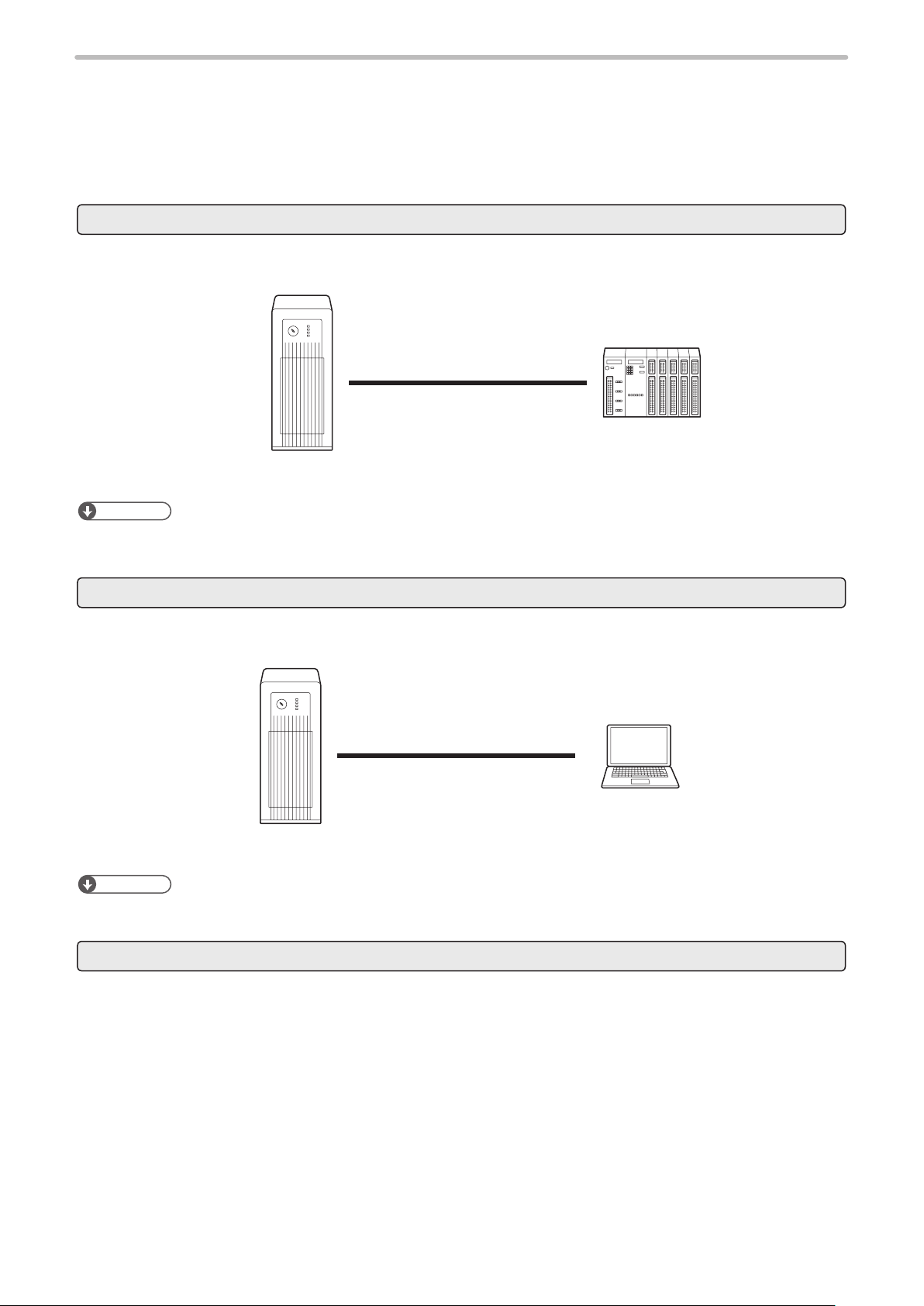
External control (remote mode) using I/O
Controls the laser marker from external devices such as PLC using I/O signals loaded into the laser marker.
For details, refer to “Setup/Maintenance Guide”.
I/O terminal block
I/O connector
Laser marker controller
ンㄆㄇㄆㄓㄆㄏㄆ
PLC, etc.
• To input marking trigger with I/O and configure other settings with a screen operation manually, use Run mode. For
details, refer to “Setup/Maintenance Guide”.
External control (remote mode) by serial communication commands (RS-232C/Ethernet)
To control the laser marker by communication commands from external devices such as PLC, use RS-232C or Ethernet
connection.
RS-232C or
Ethernet
Laser marker controller
ンㄆㄇㄆㄓㄆㄏㄆ
• It is available to the external control combining I/O and serial communication commands.
Link control with external devices (remote mode or RUN mode)
External control device
Connect the external devices, such as an image checker or a code reader, to the laser marker and control them together.
• Link control (Ethernet) with specific external devices (i.e. image checker) *1
• Link control with a code reader (RS-232C)
For details, refer to “Setup/Maintenance Guide”.
*1 : The link control with an image checker is not available at on-the-fly marking.
12
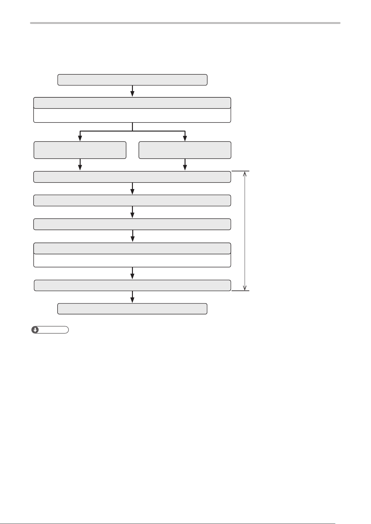
1-1-2 Operation procedure with external control
ME-LP-GS-SR-COMP-3
Operation example when controlling the laser marker from external control devices such as
⿎
PLC
Turn ON key switch of laser marker controller
Remote mode ON
Refer to “1-1-4 Remote mode settings” (P.17).
I/O control
Select file
Laser pumping ON
OPEN shutter
Confirm READY OUT is ON.
The device is ready for receiving the marking starting signal (trigger).
Trigger Input ON
Marking
Control by serial communication
commands
Control by using I/O or
communication commands
ンㄆㄇㄆㄓㄆㄏㄆ
• It is available to the external control combining I/O, and serial communication commands.
• You need to configure the system settings on the I/O communication in advance before using external control. Refer to
“1-1-3 Settings before external control” (P.14).
• For details on the operation procedure when you link an image checker or a code reader, refer to “Setup/Maintenance
Guide”.
13
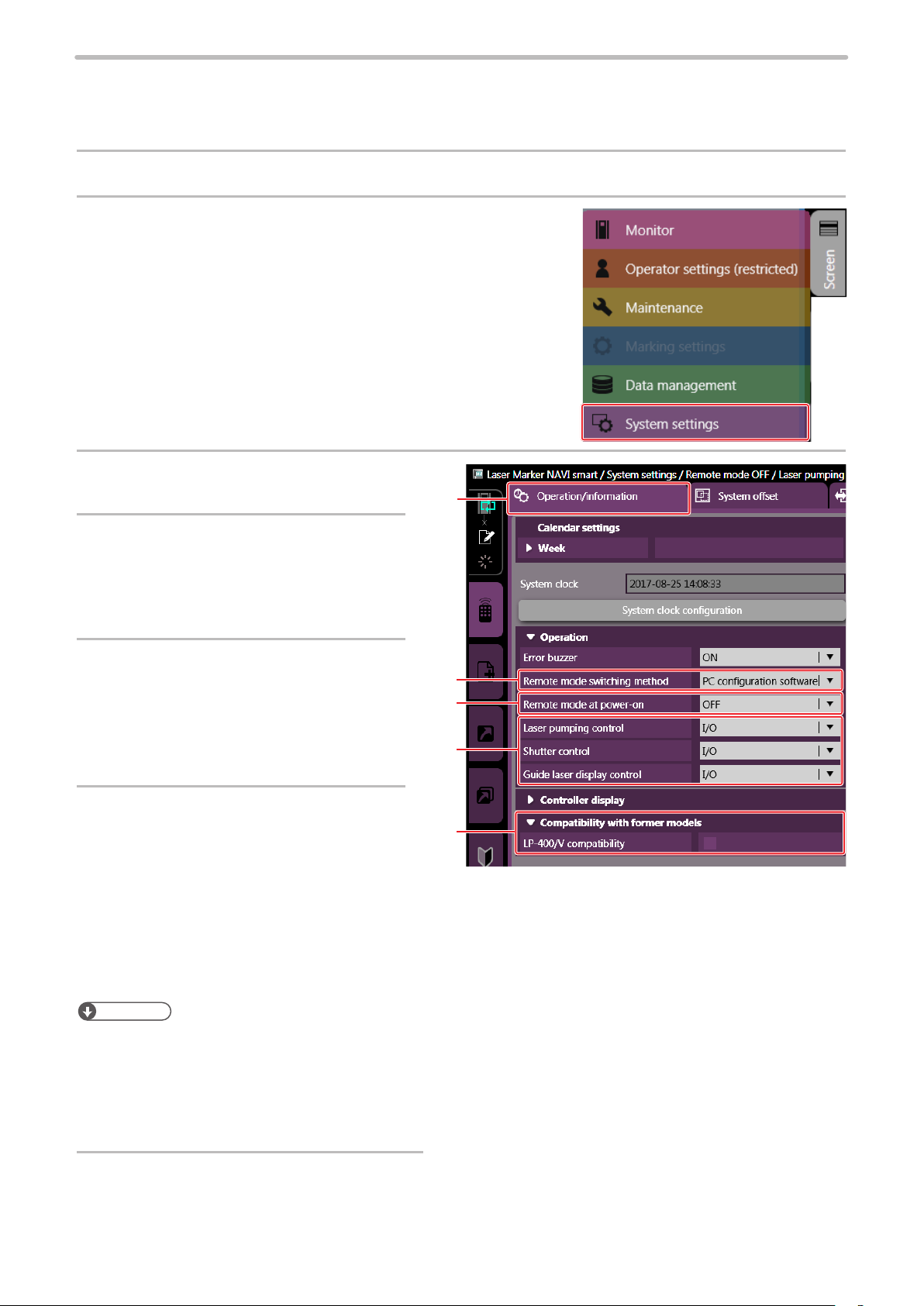
1-1-3 Settings before external control
ME-LP-GS-SR-COMP-3
To control the laser marker by using I/O or communication commands, configure the following items in advance at the
system settings of Laser Marker NAVI smart.
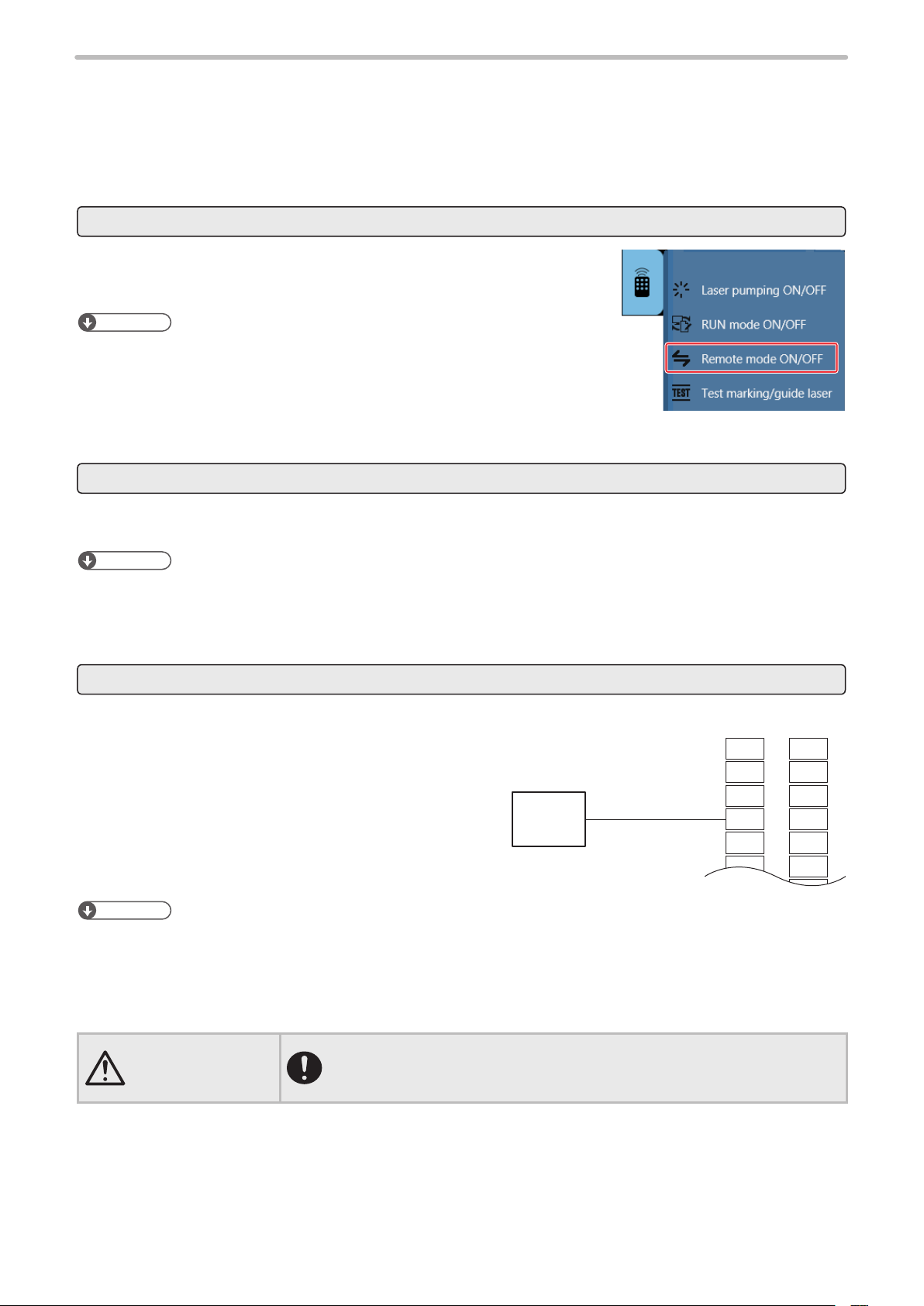
Connect the laser marker and Laser Marker NAVI smart online.
1.
Select “System settings” by clicking the screen selection
2.
menu.
Select the “Operation/Information” tab.
3.
3
Select the switching method of the
4.
remote mode.
• PC configuration software (initial setting)
• I/O
When PC configuration software is
5.
selected, select the remote mode
status at power-on.
• Remote mode ON
• Remote mode OFF (initial setting)
Select the control method for the
6.
following operations between I/O or
4
5
6
7
communication commands.
As the default, I/O control is selected to all
settings.
• Laser pumping control
• Shutter control
• Guide laser control *1
*1 : Available with LP-GS051(-L) type, LP-350S, LP-RF series and LP-RV series.
ンㄆㄇㄆㄓㄆㄏㄆ
• If you want to maintain the compatibility with LP-400/LP-V series, set the operation settings in system settings screen
corresponding with the DIP switch settings on LP-400/LP-V series. For the DIP switch details, refer to “LP- 400/V/W
series External control manual”.
• To use “Laser Radiation for Measurement Command (SPT)” of the serial communication commands, set the shutter
control method to “communication commands”.
• For LP-GS052 type, guide laser cannot be controlled using I/O or communication command.
7.
14
If you want to use the same command format with the former models of LP-400/LP-V series,
enable “LP-400/V compatibility”.
Click “Set” on the lower right corner of the screen.
ME-LP-GS-SR-COMP-3
8.
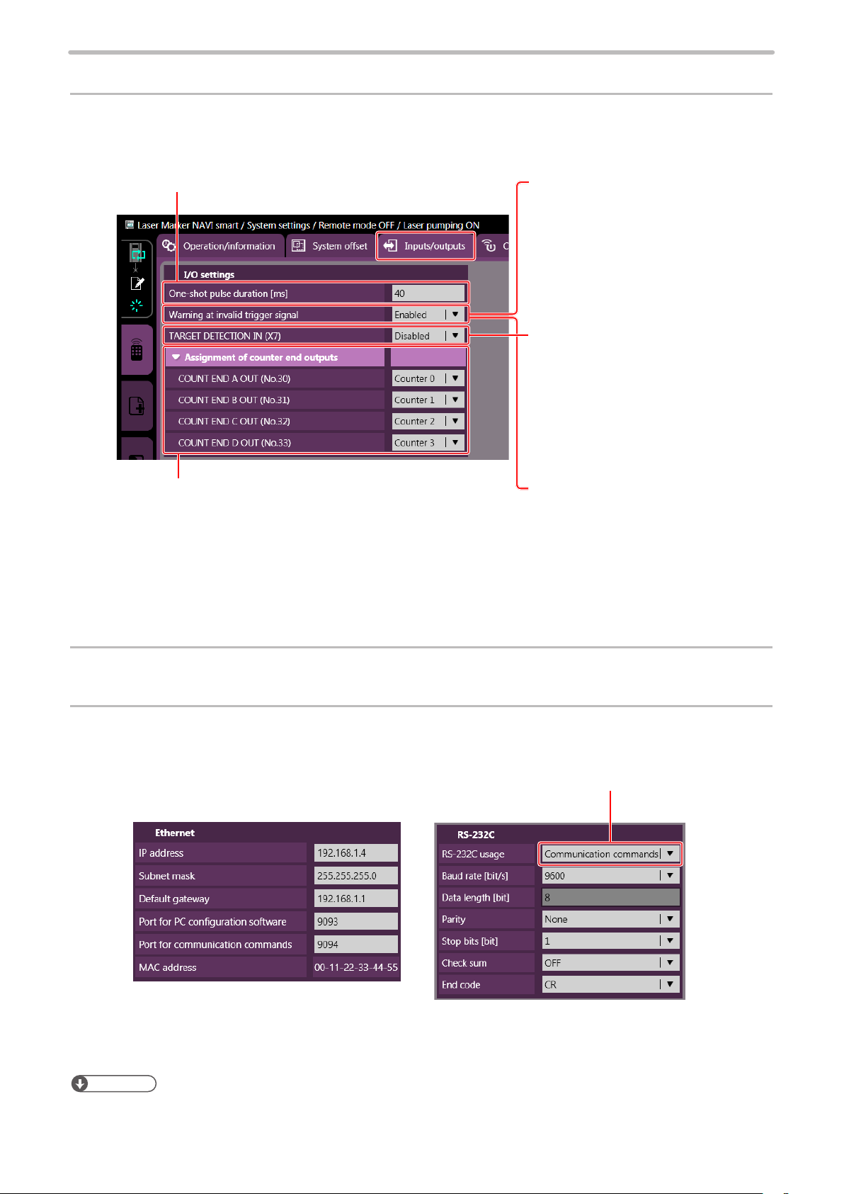
When using I/O, click the “inputs/outputs” tab and configure the following items:
9.
• One-shot pulse duration:
Configure the output time of the signal being output as
one-shot, such as PROCESSING END OUT (Y11).
Setting range: 2 to 510ms (initial value is 40ms)
• Warning at invalid trigger signal:
Configure if you will output (ON) or
will not output (OFF) the warning for
the invalid trigger. With enabling this
setting, the warning is output when the
marking trigger that cannot be accepted
was input.
(Initial setting: Enabled)
• TARGET DETECTION IN (X7) (LP-RC/
LP-RF/LP-RV series only):
Select whether or not to use TARGET
DETECTION IN on I/O terminal.
(Initial setting: Disabled)
When enabling this terminal, connect a
sensor which detect the work piece is in
position for lasing.
• Assignment of counter end outputs:
Assign the counter No. to COUNT END A OUT to COUNT
END D OUT (I/O pin No. 30 to 33).
As the default setting, counter No. 0 to 3 are assigned to
COUNT END A OUT to COUNT END D OUT respectively.
Click the “Set” button on the lower right corner of the screen.
10.
When using communication commands, click the “Communication” tab to set communication
11.
• Terminal assignment X11 (LP-GS series
only):
Select the behavior of the input signal
X11 on I/O terminal from LASER STOP
1 IN or LASER STOP 2 IN. (Initial
setting: LASER STOP 2 IN)
For the operation details of LASER
STOP, refer to “Setup/Maintenance
Gu ide”.
details of Ethernet or RS-232C.
Set “Communication commands”
to the RS-232C usage.
For Ethernet:
For RS-232C:
ンㄆㄇㄆㄓㄆㄏㄆ
• When using RS-232C, specify the “Flow control” to “None” at the communication port settings of the external control
device.
Configure the communication settings
according to the network settings.
Configure the communication settings
of the laser marker corresponding to the
external control device.
15
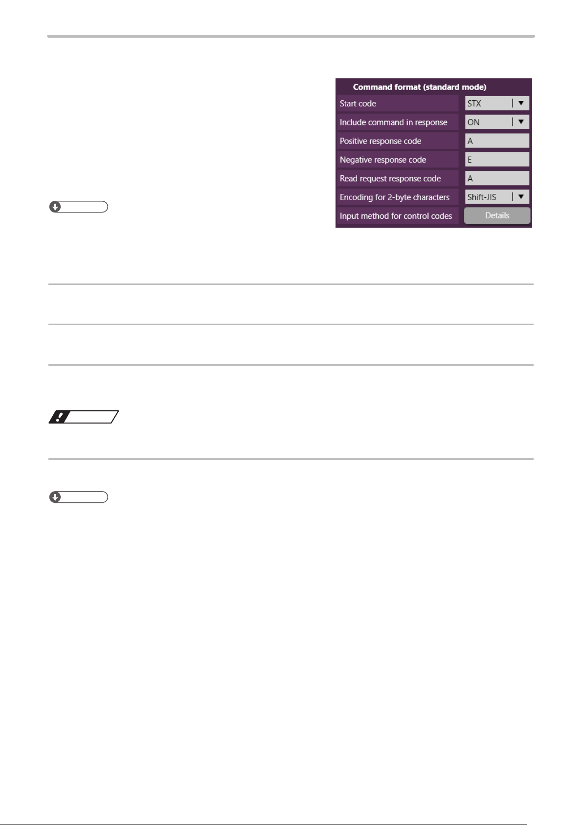
If you want to use standard command mode, specify the communication command format on the
ワㄐㄕㄊㄆ
ME-LP-GS-SR-COMP-3
12.
“Command format” panel.
• Start code: STX (initial setting) / None
• Include command in response: ON (initial setting) / OFF
• Sub-command for response data: Any single byte character
of ASCII code from 01(HEX) to 7F(HEX) can be specified.
• Initial setting of positive response code: A
• Initial setting of negative response code: E
• Initial setting of read request response code: A
• Encoding for 2-byte characters: Shift-JIS (initial setting) / GB
2312
• Input method for control codes
ンㄆㄇㄆㄓㄆㄏㄆ
• The command format settings here are applied to the standard
communication format and not applied to LP-400/LP-V compatible
format. For the details of the standard command format, refer to the “Serial Communication Command Guide”.
• For the command format of LP- 400/V compatible mode, refer to “2-3 Communication Data Format” (P.31).
Click “Set” on the lower right corner of the screen.
13.
Disconnect the online connection with the laser marker.
14.
Turn OFF the laser marker power and wait for five seconds or more, then restart.
15.
The configured items will be reflected to the laser marker.
• Do not turn the laser marker power OFF while being connected to online.
The control by the external device starts by switching the laser marker to the remote mode.
16.
ンㄆㄇㄆㄓㄆㄏㄆ
• For the details of the System settings, refer to “Laser Marker NAVI smart Operation Manual”.
16
1-1-4 Remote mode settings
WARNING
X1
X2
X3
X4
X5
X6
X7
Y1
Y2
Y3
Y4
Y5
Y6
Y7
ME-LP-GS-SR-COMP-3
To control the laser marker externally using I/O or serial communication commands, set the operation mode to the remote
mode with one of the following methods.
Select the method to switch to the remote mode on the system settings screen of Laser Marker NAVI smart. Refer to “1-1-3
Settings before external control” (P.14).
Remote mode switching by Laser Marker NAVI smart
Click the “Laser Marker Operation” tool of Laser Marker NAVI smart. Then, click
“Remote mode ON/OFF”. Click “Yes” on the confirmation screen to switch the
laser marker to the remote mode.
ンㄆㄇㄆㄓㄆㄏㄆ
• The “Remote mode ON/OFF” button is available when the following screens are
selected with the online connection established.
• Marking settings screen
• Operator settings (restricted) screen
• Monitor screen
Startup the laser marker in the remote mode (Laser Marker NAVI smart can switch the remote mode)
When you turn ON the key switch of the laser marker, the system starts in the remote mode. Use the remote mode
switch button of Laser Marker NAVI smart for releasing and resetting the remote mode.
ンㄆㄇㄆㄓㄆㄏㄆ
• If you want to start up the laser marker in the remote mode, you need to configure the settings on the system settings
screen of Laser Marker NAVI smart in advance.
• If you have configured the laser marker to start up in the remote mode, you cannot switch the remote mode from I/O.
Remote mode switching using I/O
Turn ON REMOTE IN (X4) of the I/O terminal block on the
controller.
PLC, etc.
OUTPUT
ンㄆㄇㄆㄓㄆㄏㄆ
• To enable switching to the remote mode by REMOTE IN (X4) on the I/O terminal block, you need to configure the
settings on the system settings screen of Laser Marker NAVI smart in advance.
• If you have configured the remote mode switching method to the I/O terminal block, you cannot switch the remote mode
from the Laser Marker NAVI smart screen.
REMOTE IN
I/O terminal block
• If the laser marker is set to enter the remote mode at startup or by I/O control,
construct a manual resetting system to re-pump the laser when the laser
pumping is turned to off due to an emergency stop or an interlock.
17
1-2 Serial Communication Interfaces
w
q
ME-LP-GS-SR-COMP-3
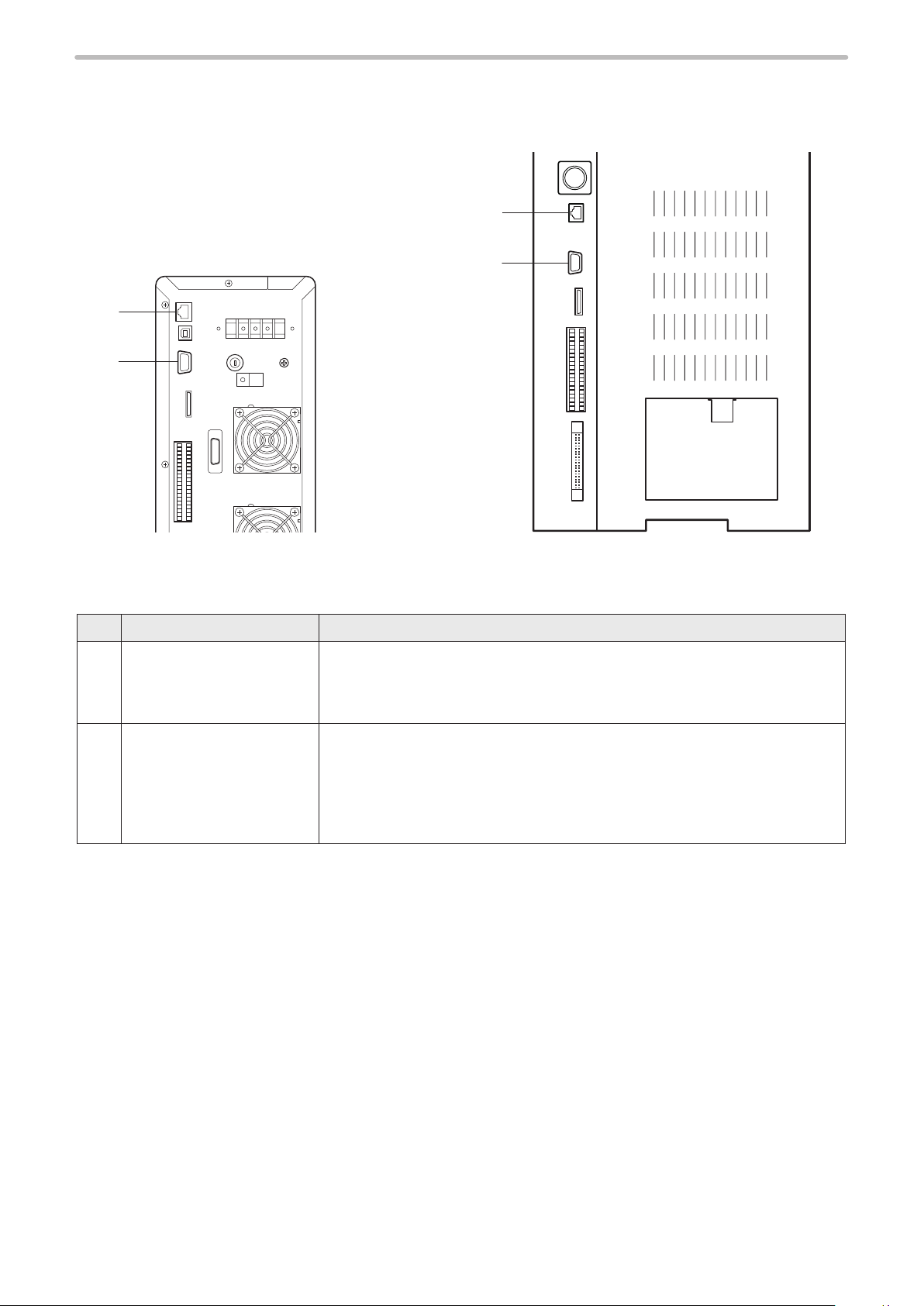
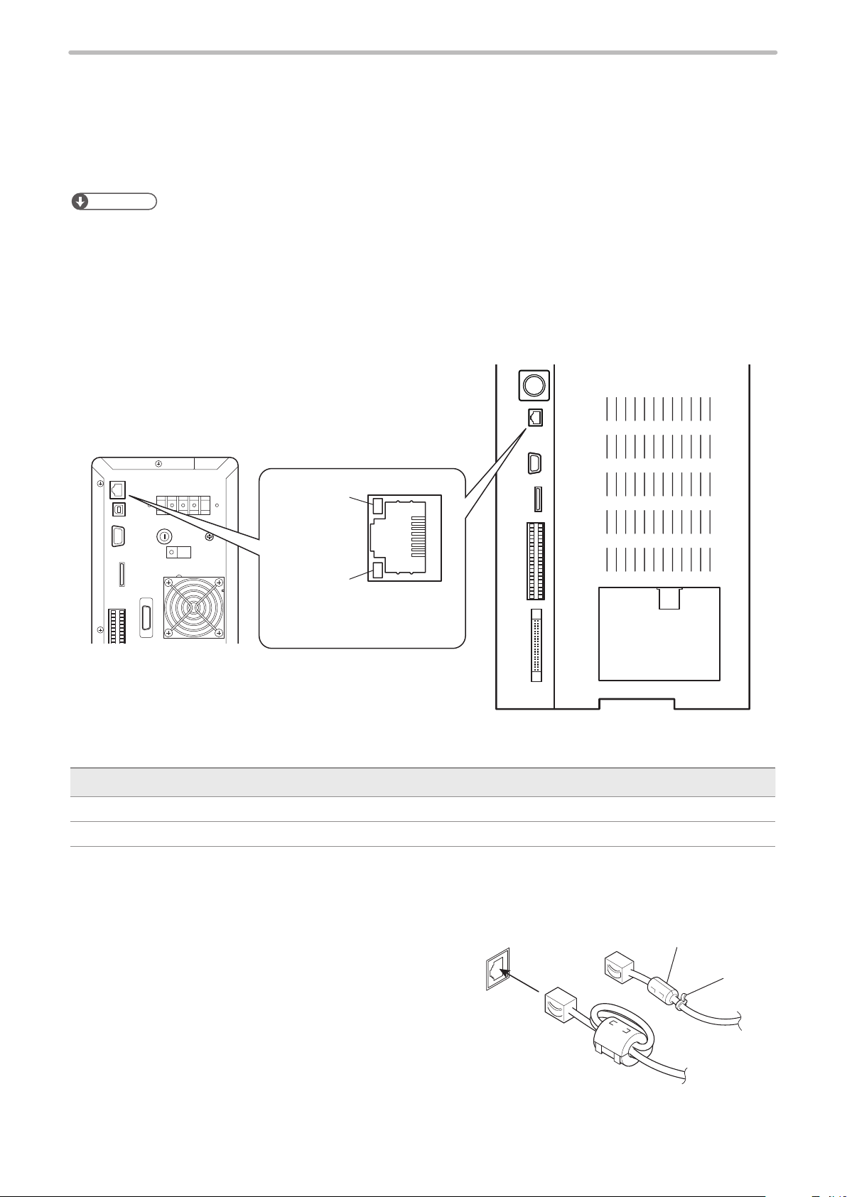
This product has the following serial communication interfaces on the controller.
w
q
LP-GS series
Rear of Controller
No. Name Description
RS-232C port For the connection details, refer to “1-3 RS-232C” (P.19).
q
To use the RS-232C port, select the RS-232C usage from communication
command control or code reader linkage function in the system settings screen in
advance.
Ethernet port For the connection details, refer to “1-4 Ethernet” (P.22).
w
The Ethernet port can be connected with the following devices simultaneously via
a HUB or a router.
• Laser Marker NAVI smart (PC configuration software)
• External device for communication command control (PLC and PC for control)
• Specific image checker
LP-RC/LP-RF/LP-RV series
Rear of Controller
18

1-3 RS-232C
ME-LP-GS-SR-COMP-3
To control the laser marker by communication commands, use RS-232C or Ethernet connection.
For the control by communication commands, configure the communication settings in advance at the system settings of
Laser Marker NAVI smart. Refer to “1-1-3 Settings before external control” (P.14).
ンㄆㄇㄆㄓㄆㄏㄆ
• The laser marker can be controlled by I/O and communication commands combined.
1-3-1 Interface specifications and connection
To execute command communication control with RS-232C, connect the RS-232C port on the controller to the external
control device.
16
59
RS-232C Port
(female)
LP-GS series
Rear of Controller
Connector position Connector specifications Model Manufacturer name
On the laser marker
side
User side D-sub 9-pin, male
Signals and Details of RS-232C connector
⿎
Terminal No. Signal Description
1 N.C. Do not use this signal.
2 TxD (SD) Transmission data: Connect RxD (RD) of the external control device
3 RxD (RD) Receiving data: Connect TxD (SD) of the external control device
D-sub 9-pin, female
Scr ew t ype: No.4-40UNC inch screw, female
Scr ew t ype: No.4-40UNC inch scr ew, male
On the laser marker
controller side
LP-RC/LP-RF/LP-RV series
Rear of Controller
- -
Recommended connector
XM3A-0921
Recommended connector cover
XM2S- 0 911
OMRON
Corporation
4 N.C. Do not use this signal.
5 GND (SG) Signal ground: Connect GND (SG) of the external control device
6 N.C. Do not use this signal.
7 N.C.
8 N.C.
9 N.C.
ンㄆㄇㄆㄓㄆㄏㄆ
• On the system settings screen, select communication command control or code reader linkage function that you use
with the RS-232C port.
• The GND pin of the RS-232C connector is common to the body of the laser marker.
19
Connecting to external control devices
ME-LP-GS-SR-COMP-3
⿎
• To connect the laser marker to the PC for control, use a commercially available RS-232C straight cable (laser marker
side: 9pin male).
• In case of connecting to PLC, a type of the cable (straight or cross) differs depending on a manufacturer or a model.
Please follow the PLC manual.
• To connect RS-232C terminal without using a commercially available RS-232C cable, connect only 3 signals of RxD,
TxD and GND and do not use other signals on the laser marker side.
• You may need a signal line connection (loop back line) other than RxD (RD), TxD (SD) or GND on the external control
device side depending on the specifications of the external control device. Read the instruction manual of the external
control device and connect it to the laser marker appropriately.
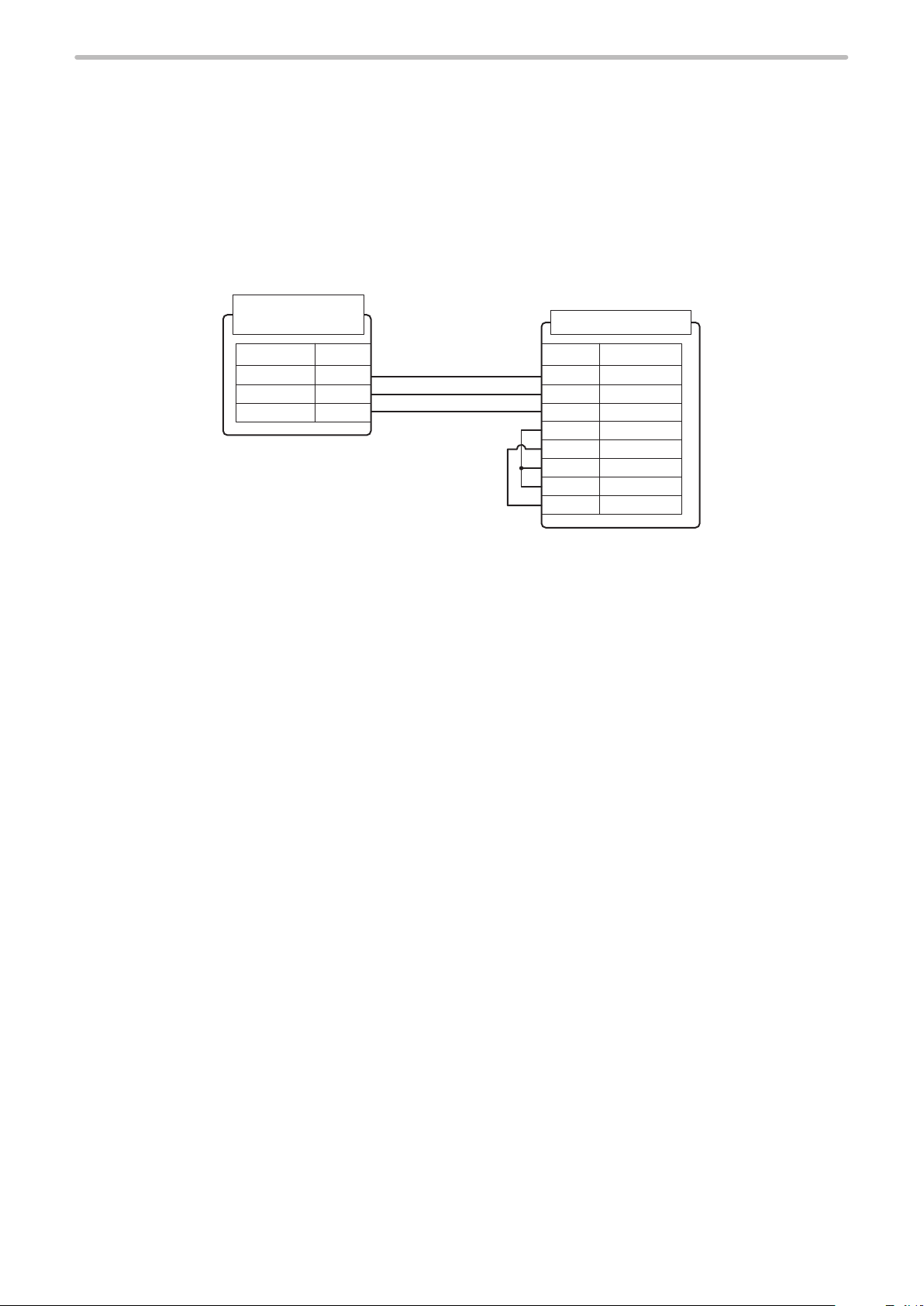
Connection example
RS-232C port
(Laser marker)
External control devise
2
3
5
TxD
RxD
GND
Straight cable
SignalSignal
RxD
TxD
GND
DCD
DTR
*
DSR
RTS
CTS
* The loop back wiring on the external control device side shown in the above figure is just an example. The wiring method
varies depending on the specifications of each external control device. Read the instruction manual of the external
control device and connect it to the laser marker appropriately.
Terminal No.Terminal No.
2
3
5
1
4
6
7
8
20
1-3-2 Communication settings (LP-400/V compatible mode)
ME-LP-GS-SR-COMP-3
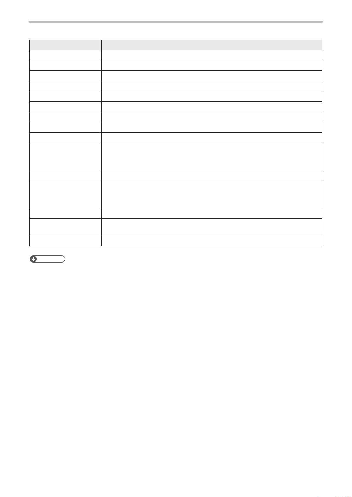
Item RS-232C communication settings (LP-400/V compatible mode)
Synchro system Start-stop method
Communication type Full-duplex transmission
Baud rate 1200 / 2400 / 4800 / 9600 / 19200 / 38400 / 57600 / 115200 bps (initial setting: 9600 bps)
Data length 8-bit fixed
Parity None / Even / Odd (initial setting: None)
Stop bits 1-bit / 2-bit (initial setting: 1-bit)
Flow control None
Check sum OFF / ON (initial setting: OFF)
End code CR / CR + LF (initial setting: CR)
Start code
• Setting request data, Readout request data, Response data for readout: STX
• Positive response code: ACK
• Negative response code: NAK
Response data command Included only in response data for readout
Sub command
• Setting request data: S
• Readout request data: R
• Response data for readout: A
Character code ASCII code
Encoding for 2-byte
characters
Shift-JIS code
Reception timer Timeout monitoring ON (10 sec.)
ンㄆㄇㄆㄓㄆㄏㄆ
• For the details of the communication settings, refer to “1-1-3 Settings before external control” (P.14).
21
1-4 Ethernet
ME-LP-GS-SR-COMP-3
1- 4 -1 Port specifications and connection
To control the laser marker by Ethernet communication, use an Ethernet port on the controller.
ンㄆㄇㄆㄓㄆㄏㄆ
• The Ethernet port of this product is compatible with both straight cable and cross cable.
• Although the maximum length of cables connecting devices permitted by the standards of Ethernet is 100 m, in order to
prevent communication failure due to noise or breakdown of the device, it is recommended to keep the length to 10 m or
less.
• The Ethernet port can be connected with the following devices simultaneously via a HUB or a router.
• PC configuration software
• External device for communication command control (PLC and PC for control)
• Specific image checker
Orange LED
Green LED
RJ-45 8-pole connector
AUTO-MDIX compatible
LP-GS series
Rear of Controller
Light up color Description
Green The indicator lights up while connected normally. It blinks during communication.
Orange Lights up only when the baud rate is 100 megabits/sec.
LAN cable connection
⿎
When you connect a LAN cable to the Ethernet port, attach
the ferrite core included to a position as close as possible
to the Ethernet port on the LAN cable controller side.
For LP-GS series, if the ferrite core diameter is too large
for the cable width, fix the ferrite core using a tie band.
For LP-RC/LP-RF/LP-RV series, turn the LAN cable 3
times around the ferrite core as shown in the figure.
On the laser marker
controller side
LP-RC/LP-RF/LP-RV series
On the laser marker
controller side
LP-RC/LP-RF/LP-RV
series
Rear of Controller
LP-GS series
Ferrite core
Tie band
22
1-4-2 Communication settings
ME-LP-GS-SR-COMP-3
Item Ethernet communication settings
Communication protocol TCP/IP
Standards IEEE802.3 (10BASE-T) / IEEE802.3u (100BASE-TX)
Applicable cable Category 5 or higher
Applicable HUB (or rooter) 10BASE-T / 100BASE-TX compatible
IP address 1.0.0.0 to 223.255.255.255 * (Initial value: 192.168.1.5)
Subnet mask 128.0.0.0 to 255.255.255.254 (Initial value: 255.255.255.0)
Default gateway 1.0.0.0 to 223.255.255.255 * (Initial value: 0.0.0.0 (Unspecified))
PC configuration software port 1025 to 65534, except 9090 (Initial value: 9093)
Command communication port 1025 to 65534, except 9090 (Initial value: 9094)
* Do not use “127” in the first octet.
ンㄆㄇㄆㄓㄆㄏㄆ
• The communication control of the laser marker through the Ethernet should be per formed in a secure network settings.
• Even the IP Address and Subnet Mask values are within the configurable range, they may not be available depending
on the combination.
• For the details of the communication settings, refer to “1-1-3 Settings before external control” (P.14).
Ethernet communication settings for communication command control
⿎
Item Ethernet communication settings (LP-400/V compatible mode)
Start code
• Setting request data, Readout request data, Response data for readout: STX
• Positive response code: ACK
• Negative response code: NAK
Response data command Included only in response data for readout
Sub command
• Setting request data: S
• Readout request data: R
• Response data for readout: A
Character code ASCII code
Encoding for 2-byte
characters
Shift-JIS code
Check sum OFF
End code CR
Reception timer Timeout monitoring ON (10 sec.)
23
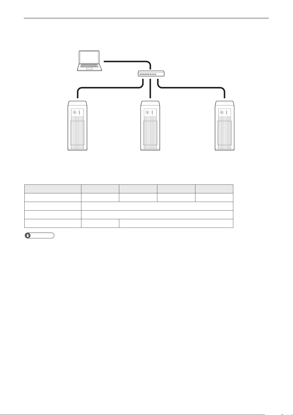
1-4-3 Connecting to external control devices and its setting sample
ME-LP-GS-SR-COMP-3
Connect the two or more laser markers and an external device via a HUB or a router:
Use a HUB (or a rooter) that supports 100BASE-TX/10BASE-T and a cable of Category 5 or higher for the connection.
External controller (PC, etc.)
Laser marker controller
(Several units connected)
HUB (or rooter)
Example of communication system settings:
Set a separate IP address not to overlap between the laser marker and PC on the network.
PC Laser marker A Laser marker B Laser marker C
IP address 192.168.1.10 19 2 .16 8 .1.5 19 2 .16 8 .1.6 19 2 .16 8 .1.7
Subnet mask 255.255.255.0
Default gateway None
Command control port — 9094
ンㄆㄇㄆㄓㄆㄏㄆ
• When the laser marker is connected the external control device one to one, no HUB is necessary.
24

1-5 Checking the communication commands
ME-LP-GS-SR-COMP-3
Check the communication commands transmitted and received by the laser marker using the command history function in
the PC configuration software “Laser Marker NAVI smart”.
The command history is displayed with the following procedures.
Connect Laser Marker NAVI smart and the laser marker online.
1.
Click the screen selection menu and select “Maintenance”.
2.
Select “Command history” tab. Up to 100 command messages received or sent by the laser
3.
marker are shown in the list.
ンㄆㄇㄆㄓㄆㄏㄆ
• In the command history the transmitted and received data via RS-232C and Ethernet ports are recorded.
• When a code reader is connected to the RS-232C port of the laser marker, the transmitted and received data with the
code reader is not recorded in the command history.
25

2 Communication Control
ME-LP-GS-SR-COMP-3
Basics

2-1 Communication Data Types
ME-LP-GS-SR-COMP-3
To control this product by communication commands, the external device transmits request data to the laser marker.
After the laser marker receives request data, it transmits the response data to the external device.
2-1-1 Request data
The request data is sent from the external device to the laser marker. The following types are applicable to the request
data.
Setting request
⿎
Request data to modify or create the laser marker data or to control the laser marker operations.
Readout request
⿎
Request data to read out the status or setting data of the laser marker.
2-1-2 Response data
The response data is sent from the laser marker to the external device. The following types are applicable to the response
data:
Positive response
⿎
Response data transmitted when the setting request data were received normally.
The positive response will be transmitted when the laser marker processing has been completed for some of the command
types.
Readout response
⿎
Response data to transmit the readout content for the readout request data.
Negative response
⿎
Response data to transmit when the request data are not acceptable.
27

2-2 Communication Sequence
ME-LP-GS-SR-COMP-3
The communication sequence of this product mainly consists of the sequence where the laser marker transmits the
response data for the (command) data requested from external devices.
As an exception, the laser marker transmits the response data automatically if you have set the response permission of the
marking end verification (MST) command.
Reception timeout
⿎
The time-out duration of this product is set to 10 seconds from receiving the telegraphic message from the head till the end
transmitted from the external device.
If a reception timeout occurs, the telegraphic message transmitted will be discarded and the laser marker will not transmit
the response data.
To resume the communication, transmit the correct telegraphic message once again.
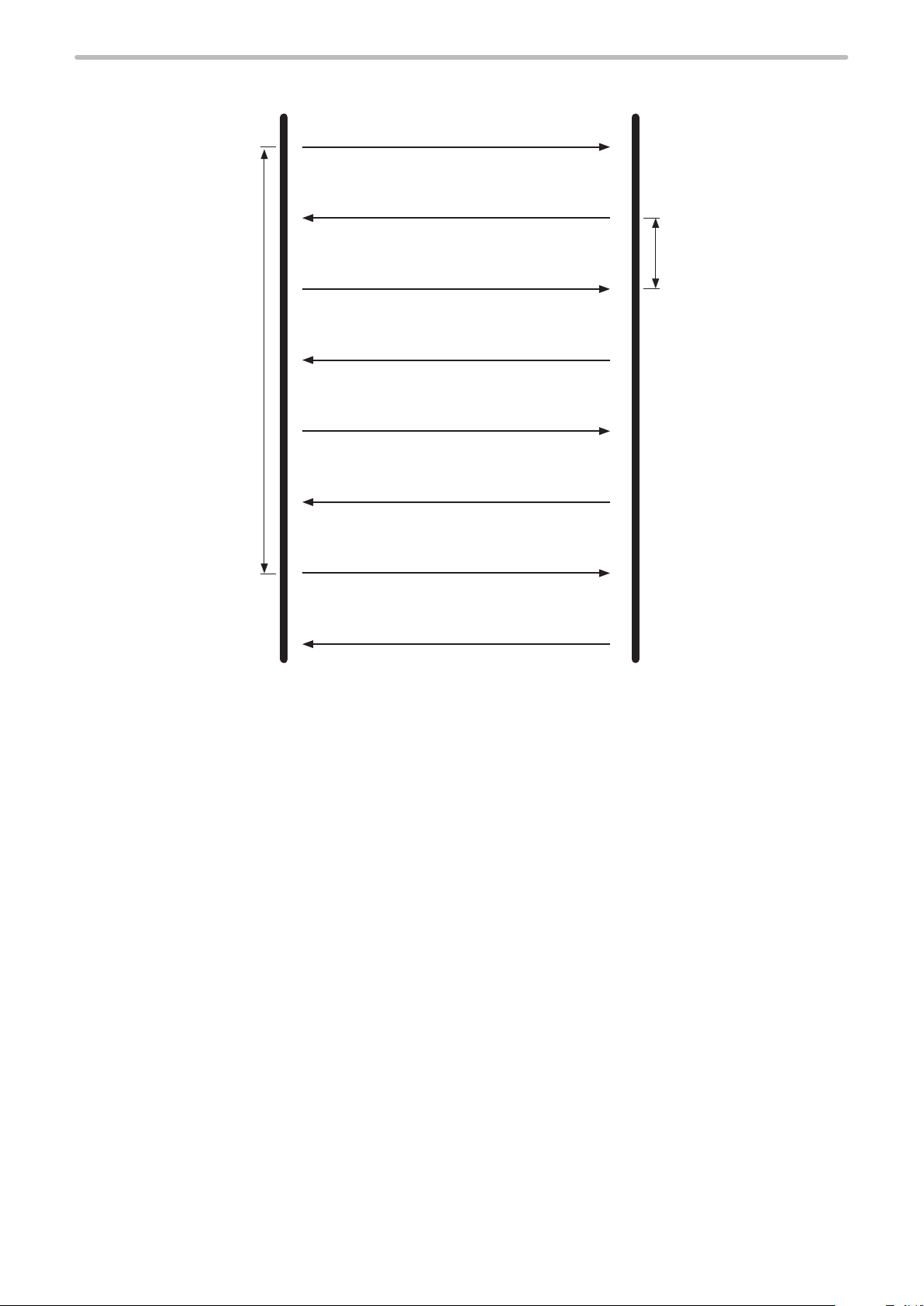
Communication sequence of setting/readout request data
⿎
When the requested data was received normally from the external device, the laser marker transmits positive response to
the setting request data and transmits readout data to the readout request data.
After sending the command, confirm the response data from the laser marker. Do not send the next command before
receiving the response.
External device
Send Receive
Receive Send
Send Receive
Receive Send
Communication sequence when the request data for setting/readout cannot be accepted
⿎
When the request data transmitted from the external device to the laser marker are not acceptable, the laser marker
transmits negative response.
External device
Send Receive
Receive Send
Command (setting request data)
Positive response (ACK)
Command (readout request data)
Readout response
Command (setting/readout request data)
Negative response (NAK)
Laser marker
Laser marker
28
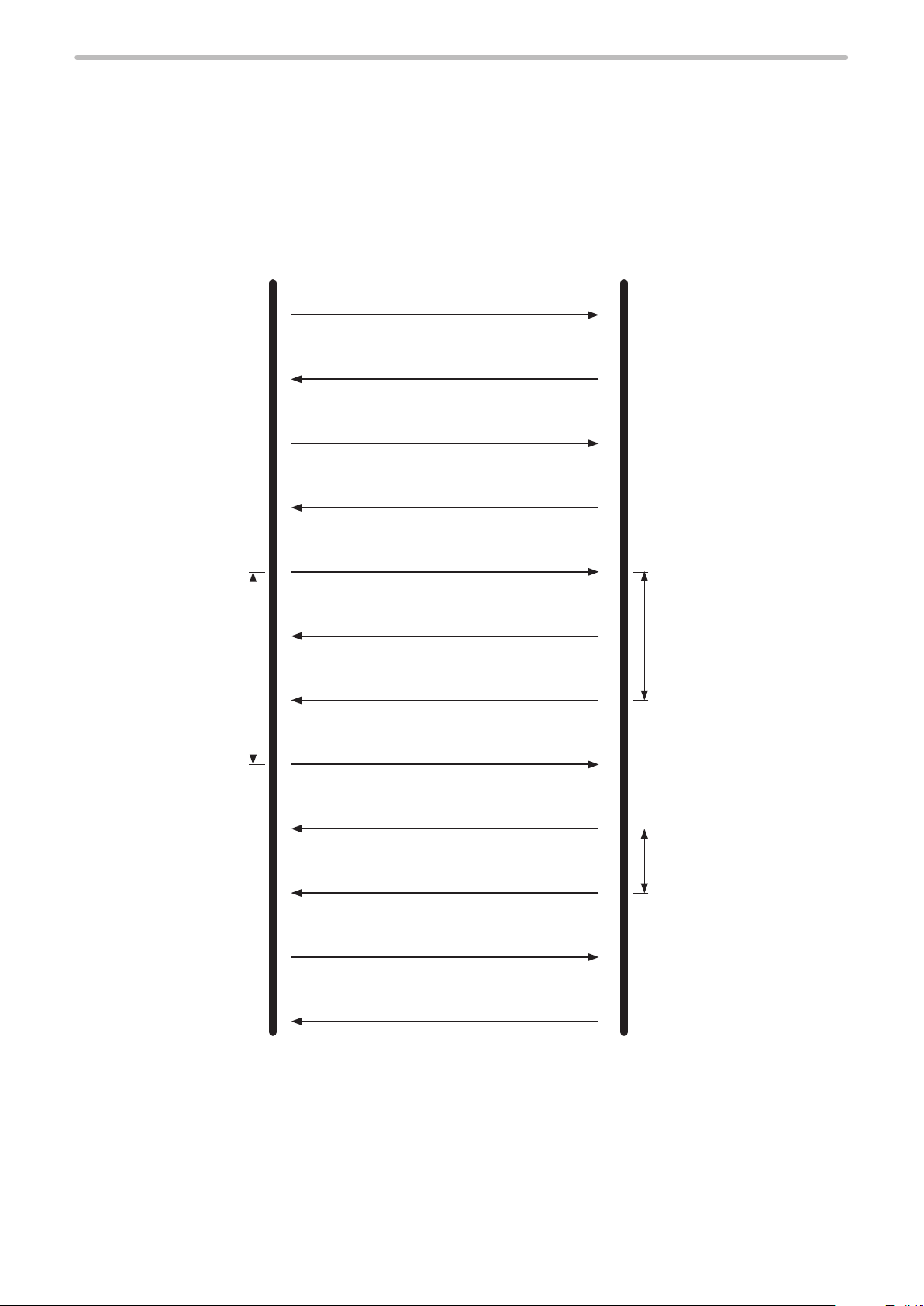
Communication sequence when the marking end verification (MST) command response is
ME-LP-GS-SR-COMP-3
⿎
enabled
The laser marker transmits the response data automatically upon completing the marking trigger processing (at the end of
marking) with the response permission setting of the marking end verification (MST) command.
This response data indicate that the marking trigger processing of the laser marker completed normally or ended
abnormally by an error.
For more information on this command, refer to “3-3-8 Marking end verification: MST” (P.63).
• When the response permission of the marking end verification (MST) command is set
Send the next request
command after
confirming the marking
completed with MST
response.
External device
Marking end verification command
(Response permission specified) : MSTS1
Positive response: ACK00
Shutter (open) command: SHTS1
Positive response: ACK00
Marking trigger command: MRKS1
Positive response: ACK00
Marking status response
(completed normally): MSTA0000
Laser marker
Marking operation
Marking trigger command: MRKS1
Positive response: ACK00
Marking status response
(abnormal end by an error): MSTAE…
Shutter (close) command: SHTS0
Positive response: ACK00
An alarm or a warning
occurred during the marking
trigger processing.
29
• When the response permission of the marking end verification (MST) command is not set
ME-LP-GS-SR-COMP-3
External device
Send the next request
command after confirming
the marking completed
with STS response.
Laser marker
Marking trigger command: MRKS1
Positive response: ACK00
Check the laser marker
status when appropriate.
Status checking command: STSR
Status readout response: STSA02100
(Marking in progress / trigger ready OFF)
Status checking command: STSR
Status readout response: STSA02110
(Non-marking state / trigger ready ON)
Marking trigger command: MRKS1
Positive response: ACK00
30
 Loading...