

Panasonic LP-GS051, LP-GS051-L, LP-GS051-LE, LP-GS051-LF, LP-GS051-LFE Setup & Maintenance Manual
...
Laser Marker
Setup /
Maintenance Guide
LP-GS series
ME-LPGS-SM-8
2019. 4
Please read these instructions carefully before using this
product, and save this manual for future use.
panasonic.net/id/pidsx/global

Preface
ME-LPGS-SM-8
Thank you for purchasing our product.
For full use of this product safely and properly, please read this document carefully.
This product has been strictly checked and tested prior to its delivery. However, please make sure that this product
operates properly before using it. In case that the product becomes damaged or does not operate as specified in this
document, contact the dealer you purchased from or our sales office.
General terms and conditions of this document
⿎
1. Before using this product, or before every starting operation, please confirm the correct functioning and performance
of this product.
2. Contents of this document could be changed without notice.
3. This document must not be partially or totally copied or revised.
4. All efforts have been made to ensure the accuracy of all information in this document. If there are any questions,
mistakes, or comments in this document, please notify us.
5. Please remind that we assume no liability for any results arising out of operations regardless of the above clauses.
Disclaimer
⿎
The applications described in this document are all intended for examples only. The purchase of our products described in
this document shall not be regarded as granting of a license to use our products in the described applications. We do NOT
warrant that we have obtained some intellectual properties, such as patent rights, with respect to such applications, or that
the described application may not infringe any intellectual property rights, such as patent rights, of a third party.
Trademark
⿎
• Windows is a registered trademark or trademark of Microsoft Corporation in the United States and/or other countries.
• QR Code is a registered trademarks of DENSO WAVE INCORPORATED.
• Adobe, Adobe Logo, Adobe Reader, and Adobe Illustrator are either registered trademarks or trademarks of Adobe
Systems Incorporated in the United States and/or other countries.
• Bluetooth is a registered trademark of U.S.A. Bluetooth SIG Inc.
• All other product names and companies provided in this document are trademarks or registered trademarks of their
respective companies.
2
DANGER
WARNING
CAUTION
DANGER
ALWAYS FOLLOW THESE IMPORTANT
ME-LPGS-SM-8
Cautions in Handling
To reduce the risk of injury, loss of life, electric shock, fire, malfunction, and damage to equipment or property, always
observe the following safety precautions.
The following symbols are used to classify and describe the level of hazard, injury, and property damage caused when the
denotation is disregarded and improper use is performed.
Denotes a potential hazard that will result in serious injury or death.
Denotes a potential hazard that could result in serious injury or death.
Denotes a hazard that could result in minor injury.
The following symbols are used to classify and describe the type of instructions to be observed.
This symbol is used to alert users to a specific operating procedure that must not be performed.
This symbols is used to alert users to a specific operating procedure that must be followed in order to
operate the unit safely.
SAFETY PRECAUTIONS!
This symbols is used to alert users to a specific operating procedure that must be performed carefully.
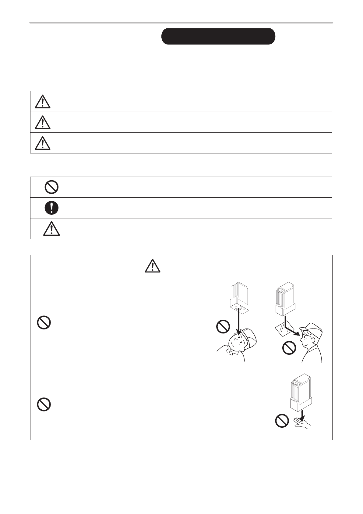
• Never look at laser beam directly, through lens or
through any other optical components. Laser beam
radiation into the eye causes blindness or serious
damage to the eye.
Not only the direct beam of laser, but also diffused
reflected beam is harmful.
• Never touch laser beam and avoid human skin, clothing and any other
flammable object from laser beam exposure directly.
Burning into deep skin might result and there is a risk of fire.
3
WARNING
• Do not use this product anywhere where fire is strictly prohibited, near inflammable gas, objects or organic
ME-LPGS-SM-8
solvents such as thinner or gasoline, or in dusty place. There is a risk of fire.
• Do not use this product in wet place. In addition, never conduct wiring or maintenance work with wet hands
or when the product surface is wet. Otherwise, electric shock and/or malfunction may result.
• Never disassemble the product.
Doing so may cause exposure to the laser beam or electric shock.
• Do not insert hands or objects between the gaps of the exhaust port or intake port. There is a risk of
electrical shock or injury.
• Take laser protection measures required to use Class 4 laser products subject to the local laws and
regulations of the country or region in which this laser product is used.
• To protect the operators' eyes, make it mandatory to wear goggles against laser beam
within the laser controlled area. The protective goggles can momentarily protect the
eyes against the scattered beam. Never look at the direct beam or reflected beam
even when you are wearing the protective goggles.
• Set protective enclosure with proper reflectance, durability and thermal resistance to enclose the laser
radiation area without leakage.
• Construct an interlock systems such as a function to stop laser radiation for the maintenance door of the
protective enclosure.
• After power supply of laser marker is turned off, laser safety manager must remove the key and keep it.
• Be sure to connect the head and controller of the laser marker which have the same model number.
Otherwise there is a risk of exposure to laser radiation or failure.
• Read all packaged guides and manuals thoroughly, and do not operate, install and connect the laser
marker with any other methods except the instructions provided in the manuals. If the product is used in a
manner not specified by the instruction, the safety protection and functions provided by the device may be
impaired and may cause injury, electrical shock or exposure of laser beam.
• Prior to wiring, cable connecting, and/or maintenance work, ensure that all the power switches are turned
off. Otherwise, electrical shock may result.
• The wiring and maintenance must be conducted by the electrical engineers or under their supervision.
Incorrect work may cause electrical shock.
• Connect ground wire before using. A failure or electrical leakage that occurs when the unit is not properly
grounded may result in electric shock.
4
WARNING
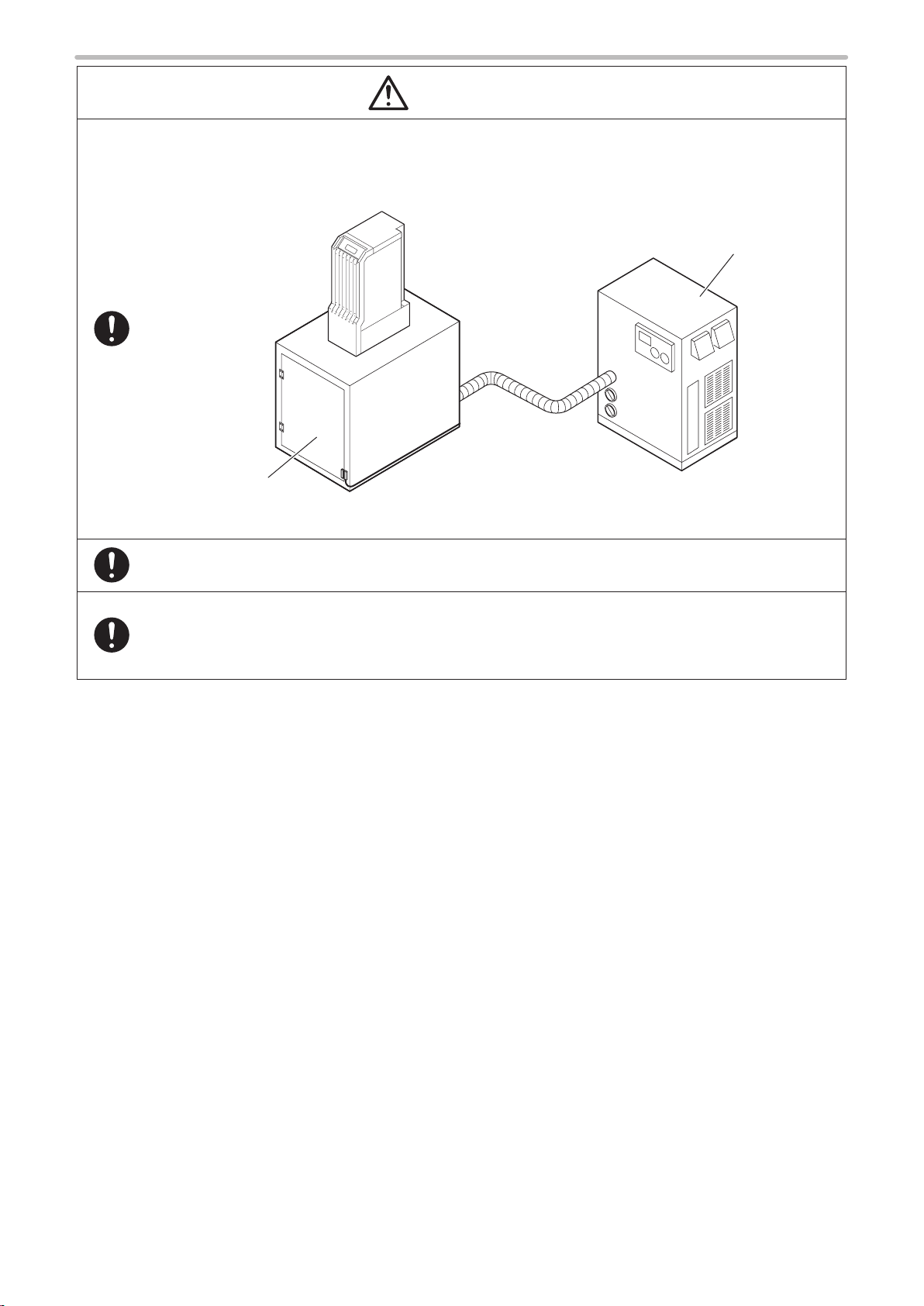
• Remove the dust and/or gas which may be generated during the laser radiation with dust collector or
ME-LPGS-SM-8
exhauster. Use an appropriate dust collector or exhauster for dust or gas generated.
Depending on the material of the objects, harmful dust and/or gas to the human body and the laser marker
may be generated.
Dust collector
Protective
enclosure
• When using the assist gas for laser processing, take safety precautions to protect operators from
exposure, ignition, toxic effect, excess or lack of oxygen.
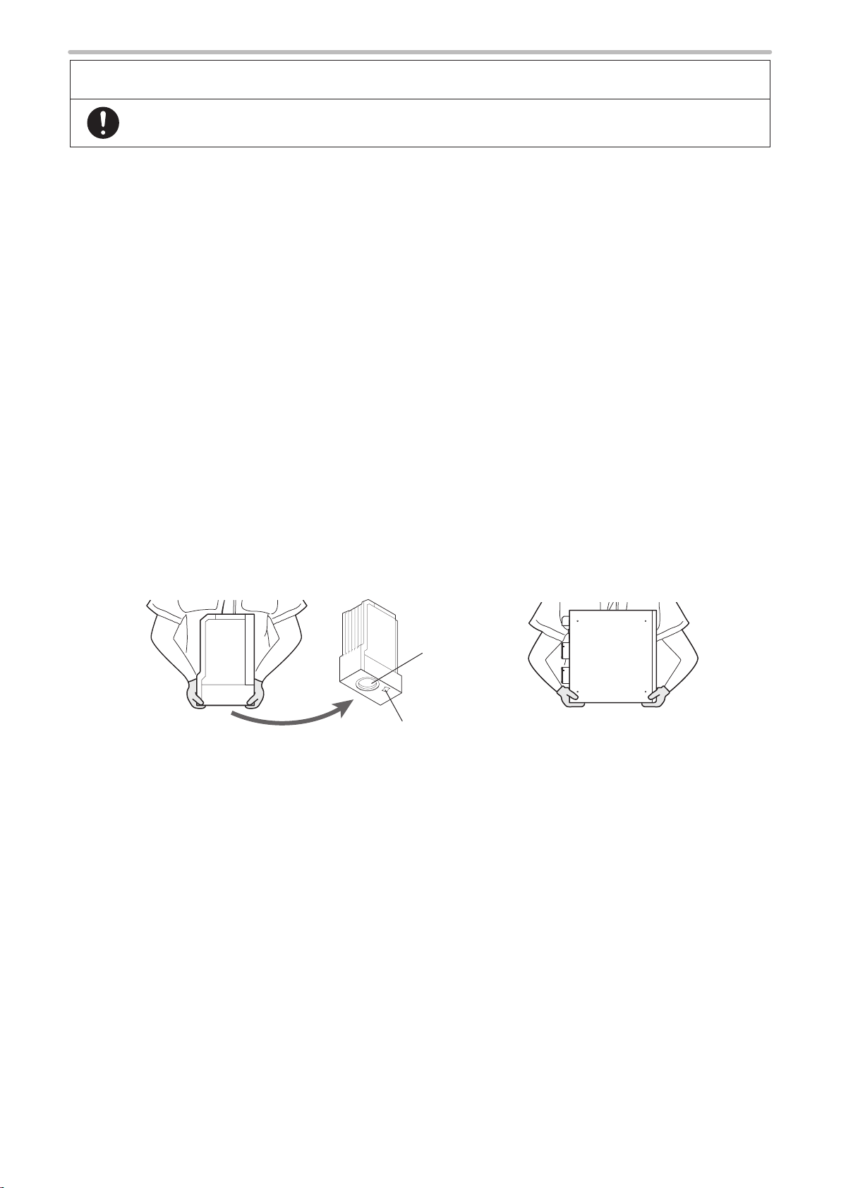
• To carry this product, wear the non-slip gloves. Hold the product with both hands. Do not hold the cables
or connectors at carrying.
• Install this product in the stable place without vibration and shock.
• In case it falls down, it may cause injury.
5
For the Proper Use of Product
ME-LPGS-SM-8
• Be sure to observe the following matters to prevent a failure or a malfunction of this product and to
maintain the product performance properly.
Operating environment
• Do not use the product in a place with frequent vibrations or shocks. Moreover, please do not drop this product. It may
affect the precision component and optical component inside, which could impair the performance or result in a failure.
• Do not use the system outdoors.
• This product uses the air cooling system as the laser cooling method. Please install not to bar the flow of air cooling.
Avoid placing heat sources near the product.
• Be sure to use the product within the ambient temperature and humidity defined in the specifications.
• Be careful not to have water, oil, fingerprints, dust, or dirt attached to the laser emission port of the head. This could
degrade the marking performance and may result in a failure. If the laser emission port becomes dirty, use a dry soft
cloth to clean the port.
• If the air filter becomes dirt, clean the filter without delay. Failure to do so may hinder the air flow, resulting in failure of
this product. Make sure to replace the air filter on a periodic basis.
• Ensure that the dust or gas is removed by placing the intake duct of the dust collector or exhauster near the source of
dust or gas. Any dust or gas contamination on the laser emission port may cause failure or decrease the laser marking
or processing quality. In addition, when the laser beam is blocked by dust or gas, it may cause decrease in laser marking
quality.
Installation
• To carry this product, wear the non-slip gloves. Hold the product with both hands. Do not hold the cables or connectors
at carrying.
• Do not touch the laser emission port on the bottom of the head. It may affect the marking quality badly.
• Carry this product as shown in the figure below.
Head Controller
Laser emission
port
Laser pointer
emission port
• Be careful not to apply excess force to the cable or not to nip the cable at the installation.
• Verify the minimum bend radius of each cable and install them without excess forces being applied.
• Do not hit the device with a tool such as a hammer at the installation. Do not use excessive force while tightening the
screws (nuts). It may cause a failure.
• Do not insert foreign objects to the exhaust port of each unit or the gaps between units.
• Use anti-reflection material (ex. black paint for metal) for an external shutter or a protective enclosure in a path of laser
beam. It may cause a failure of the components inside the laser marker head.
• If any other devices such as a sensor or a camera are installed near the laser marker, make sure that these devices are
installed in the place where laser beam and its reflected beam do not damage to them.
6

For the Proper Use of Product
ME-LPGS-SM-8
• Be sure to observe the following matters to prevent a failure or a malfunction of this product and to
maintain the product performance properly.
Wiring
• Verify that the cables are wired correctly before powering on.
• For the connection of this product, use the dedicated cables attached to the product or the specified optional cables.
• Check the voltage fluctuations of the power supply. Do not input the power supply exceeding the rating.
• If a surge occurs in the power supplied, connect a surge absorber to a source of the surge to absorb it.
• Be sure to take measures against surge before connecting any induction load such as DC relay to the load.
• The output has no protection function for short-circuit; therefore, do not connect the power supply or capacitive load
directly.
• Make sure to ground the frame ground (F.G.) terminal and the protective conductor terminal of this product.
• Install such that the controller housing and the head housing are at the same electric potential.
• Each connecting cable should not be used in the same raceway or connected in parallel to any device that generates
high-tension wires, power lines, large switching surge or the like. There is a risk of malfunction caused by induction.
• USB cable should not be connected in parallel with the AC power cable or the motor power cable.
• Make the wiring as short as possible to prevent a malfunction by the noise.
Operation
• Do not power off until the startup has completed since turning on the laser marker power.
• To power on the laser marker again, wait for 5 seconds or more since turning off the power, then turn it on again.
• The following items, Date, Lot, and Expiry Date are marked based on the system clock of the laser marker. The system
clock might be deviated due to error of the internal parts or degree of the battery drain, ambient temperature and
humidity. Therefore, be sure to check the time of the system clock before the operation without fail.
Others
• Be sure to delete all registered data when transferring or discarding this product. Retained data might result in illegal
read out and leaking of information by a third-party with malicious intent.
7

Order Placement Recommendations and Considerations
ME-LPGS-SM-8
The Products and Specifications listed in this document are subject to change (including specifications, manufacturing facility and
discontinuing the Products) as occasioned by the improvements of Products. Consequently, when you place orders for these Products,
Panasonic Industrial Devices SUNX asks you to contact one of our customer service representatives and check that the details listed in
the document are commensurate with the most up-to-date information.
SAFETY PRECAUTIONS
Panasonic Industrial Devices SUNX is consistently striving to improve quality and reliability. However, the fact remains that electrical
components and devices generally cause failures at a given statistical probability. Furthermore, their durability varies with use
environments or use conditions. In this respect, check for actual electrical components and devices under actual conditions before use.
Continued usage in a state of degraded condition may cause the deteriorated insulation. Thus, it may result in abnormal heat, smoke
or fire. Carry out safety design and periodic maintenance including redundancy design, design for fire spread prevention, and design
for malfunction prevention so that no accidents resulting in injury or death, fire accidents, or social damage will be caused as a result of
failure of the Products or ending life of the Products.
The Products are designed and manufactured for the industrial indoor environment use. Make sure standards, laws and regulations in
case the Products are incorporated to machinery, system, apparatus, and so forth. With regard to the mentioned above, confirm the
conformity of the Products by yourself.
Do not use the Products for the application which breakdown or malfunction of Products may cause damage to the body or property.
i) usage intended to protect the body and ensure security of life
ii) application which the performance degradation or quality problems, such as breakdown, of the Products may directly result in
damage to the body or property
It is not allowed the use of Products by incorporating into machinery and systems indicated below because the conformity, performance,
and quality of Products are not guaranteed under such usage.
i) transport machinery (cars, trains, boats and ships, etc.)
ii) control equipment for transportation
iii) disaster-prevention equipment / security equipment
iv) control equipment for electric power generation
v) nuclear control system
vi) aircraft equipment, aerospace equipment, and submarine repeater
vii) burning appliances
viii) military devices
ix) medical devices (except for general controls)
x) machinery and systems which especially require the high level of reliability and safety
ACCEPTANCE INSPECTION
In connection with the Products you have purchased from us or with the Products delivered to your premises, please per form an
acceptance inspection with all due speed and, in connection with the handling of our Products both before and during the acceptance
inspection, please give full consideration to the control and preservation of our Products.
WARRANTY PERIOD
Unless otherwise stipulated by both parties, the warranty period of our Products is one year after the purchase by you or after their
delivery to the location specified by you.
The consumable items such as battery, relay, filter and other supplemental materials are excluded from the warranty.
SCOPE OF WARRANTY
In the event that Panasonic Industrial Devices SUNX confirms any failures or defects of the Products by reasons solely attributable to
Panasonic Industrial Devices SUNX during the warranty period, Panasonic Industrial Devices SUNX shall supply the replacements of
the Products, parts or replace and/or repair the defective portion by free of charge at the location where the Products were purchased or
delivered to your premises as soon as possible.
However, the following failures and defects are not covered by warranty and we are not responsible for such failures and defects.
(1) When the failure or defect was caused by a specification, standard, handling method, etc. which was specified by you.
(2) When the failure or defect was caused after purchase or delivery to your premises by an alteration in construction, performance,
specification, etc. which did not involve us.
(3) When the failure or defect was caused by a phenomenon that could not be predicted by the technology at purchasing or contracted
time.
(4) When the use of our Products deviated from the scope of the conditions and environment set forth in the instruction manual and
specifications.
(5) When, after our Products were incorporated into your products or equipment for use, damage resulted which could have been
avoided if your products or equipment had been equipped with the functions, construction, etc. the provision of which is accepted
practice in the industry.
(6) When the failure or defect was caused by a natural disaster or other force majeure.
(7) When the equipment is damaged due to corrosion caused by corrosive gases etc. in the surroundings.
8
The above terms and conditions shall not cover any induced damages by the failure or defects of the Products, and not cover your
production items which are produced or fabricated by using the Products. In any case, our responsibility for compensation is limited to the
amount paid for the Products.
SCOPE OF SERVICE
The cost of delivered Products does not include the cost of dispatching an engineer, etc.
In case any such service is needed, contact our sales representative.

Applicable Standards and Related Regulations
ME-LPGS-SM-8
Applicable standards
This product conforms to the following standards.
Note that our products do not conform to the safety standards of the countries and regions not listed in the applicable
standards section. When exporting this product by itself or integrated into machine or device, confirm the regulations and
standards of the exporting country or region.
Model Applicable standards and regulations
LP-GS 051
LP-GS 051- E
LP-GS 051-F
LP-GS 051-FE
LP-GS 051-FN
LP-GS 051- L
LP-GS 051- LE
LP-GS 051- LF
LP-GS 051- LF E
LP-GS 051- LF N
LP-GS052
LP-GS052-E
LP-GS052-F
LP-GS052-FE
LP-GS052-FN
JIS (Japanese Industrial Standards)
• JIS C 6802: 2014 “Safety of laser products”
FDA (Food and Drug Administration) Regulations
• 21 CFR1040.10 and 1040.11 except for deviations pursuant to Laser Notice No. 50 “PART 1040
PERFORMANCE STANDARDS FOR LIGHT-EMITTING PRODUCTS”
EN Standard (CE Marking) *1
• 2014/30/EU “EMC Directive”
• EN55011: 2009+A1: 2010 “Industrial, scientific and medical equipment. Radio-frequency
disturbance characteristics. Limits and methods of measurement”
• EN61000-6-2: 2005 “Electromagnetic compatibility (EMC). Generic standards. Immunity for
industrial environments”
• 2014/35/EU “Low Voltage Directive”
• EN60204-1: 2006+A1: 2009 “Safety of machinery. Electrical equipment of machines. General
requirements”
• EN60825-1: 2014 “Safety of laser products. Equipment classification and requirements”
• 2011/65/EU “RoHS Directive”
• EN 50581:2012 “Technical documentation for the assessment of electrical and electronic
products with respect to the restriction of hazardous substances”
GB (Chinese National Standard)
• GB 7247.1-2012 (idt IEC60825 -1: 2007) “
KC mark (Korea Certification) *2
Class A Equipment (Industrial Broadcasting & Communication Equipment)
This equipment is Industrial (Class A) electromagnetic wave suitability equipment and seller or user
should take notice of it, and this equipment is to be used in the places except for home.
A 급 기기 ( 업무용 방송통신기자재 )
이 기기는 업무용 (A 급 ) 전자파적합기기로서 판매자 또는 사용자는 이 점을 주의하시기 바라며 ,
가정외의 지역에서 사용하는 것을 목적으로 합니다 .
激光产品的安全 第 1 部分 : 设备分类、要求”
*1 : Contact for CE:
Panasonic Marketing Europe GmbH, Panasonic Testing Center
Winsbergring 15, 22525 Hamburg, Germany
*2 : This standard is not applicable to the laser marker models with Bluetooth function (LP-GS051/LP-GS051-E/LP-
GS051-L/LP-GS051-LE/LP-GS052/LP-GS052-E).
• Construct a safety system before using this product as it is a class 4 laser product.
• While constructing the system, check ISO 13849-1 and ISO 11553-1, and take the required safety measures
accordingly.
Please see the “Laser Safety Guide” for details.
ンㄆㄇㄆㄓㄆㄏㄆ
• Besides the above mentioned standards and regulations, certain regulations required to a wireless terminal equipment
are applicable to the laser marker models with Bluetooth function (LP-GS051/LP-GS051-E/LP-GS051-L/LP-GS051-LE/
LP-GS052/LP-GS052-E). Refer to “Using Bluetooth (wireless terminal equipment)” (P.11).
9

Implementing safety measures for the laser products
ME-LPGS-SM-8
This product falls into Class 4 laser product according to IEC60825-1 “Safety of Laser Products”, FDA standards 21 CFR
1040.10 and JIS C 6802.
By definition, class 4 lasers are “Laser products for which intrabeam viewing and skin exposure is hazardous and for which
the viewing of diffuse reflections may be hazardous. These lasers also often represent a fire hazard.”
To protect the operator from being exposed to a laser beam, be sure to follow the instructions in attached “Laser Safety
Guide” and safety regulations in each country or region.
Removing and eliminating dust or gas
Depending on the laser radiation objects, noxious dust or gas may generate by the laser radiation, which could harm
human body or the environment.
Eliminate dust or gas generated using a dust collector or an exhauster according to the constituent of such dust or gas.
Dispose of the exhaust gas safely and appropriately according to the laws and regulations of the country, region, or area
applicable.
Attention for the laser marker disposal
For disposal of this product, segregate and dispose of it appropriately according to the laws and regulations of the country,
region, or area applicable.
Refer to “7-5 Disposal of Laser Marker” (P.160).
10

Using Bluetooth (wireless terminal equipment)
ME-LPGS-SM-8
To use wireless equipment, you need to obtain the authorization required by the country or the region where you use the
equipment. Emitting radio waves in the area without an authorization is subject to punishment by the laws and regulations
of each region.
Some of the models of this product can be used with Bluetooth. The wireless equipment loaded into these models has
acquired the following certifications:
Model Applicable standards and regulations
LP-GS 051
LP-GS 051- E
LP-GS 051- L
LP-GS 051- LE
LP-GS052
LP-GS052-E
*1 : FCC Remarks
• If you alter or modify the product without the authorization from the organization that controls the product
conformance, the user may lose the right to operate this device.
• Do not install the transmitter of this product (loaded onto the head front panel) in the same place as the other
antennas or transmitters or operate them together.
• To comply with the radio frequency emission limit value of FCC, keep 20 cm or more between the antenna (head
front panel area) and human body for the installation and operation.
*2 : Contact for CE:
Panasonic Marketing Europe GmbH
Panasonic Testing Center
Winsbergring 15, 22525 Hamburg, Germany
*3 : Hereby, Panasonic Industrial Devices SUNX declares that LP-GS051/LP-GS051-E/LP-GS051-L/LP-GS051-LE/LP-
GS052/LP-GS052-E are in compliance with the essential requirements and other relevant provisions of Directive
2014/53/EU. The declaration of conformity is available at
http://www.ptc.panasonic.eu/filedepot
*4 : Referenced standard
Japan: Type of the specified wireless equipment: “Article 2 Section 1 No. 19 wireless equipment
2.4 GHz bandwidth upgraded low power data communication system” “certification of construction
type” (Article 38 Section 24 Paragraph 1, Japanese Radio Law)
USA: FCC CFR 47 Part15 Subpart C *1
EU Zone: ETSI EN Standard (CE marking) *2
2014/53/EU “RE Directive” *3
• ETSI EN 300 328 V2.1.1 (2016-11) “Wideband transmission systems; Data transmission
equipment operating in the 2,4 GHz ISM band and using wide band modulation techniques;
Harmonized Standard covering the essential requirements of article 3.2 of Directive 2014/53/
EU”
• ETSI EN 301 489-1 V1.9.2(2011-09) “Electromagnetic compatibility and Radio spectrum Matters
(ERM); ElectroMagnetic Compatibility (EMC) standard for radio equipment and services; Part 1:
Common technical requirements” *4
• ETSI EN 301 489-17 V2.2.1(2012-09) “ElectroMagnetic compatibility and Radio spectrum
Matters (ERM); ElectroMagnetic Compatibility (EMC) standard for radio equipment and services;
Part 17: Specific conditions for Wideband data and HIPERLAN equipment” *4
• EN 62311:2008 “Assessment of electronic and electrical equipment related to human exposure
restrictions for electromagnetic fields (0 Hz - 300 GHz)” *4
Attention for using Bluetooth
The wireless equipment loaded onto this product uses the frequency band of 2.4 GHz.
The followings are operated within the applicable frequency bandwidth of this device: the premises radio station (license
required) for mobile identification used in a production line of factories in addition to the industrial, scientific, and medical
equipment including microwaves, the specified low power radio stations (no license required) and amateur radio station
(license required).
• Make sure that there is no active premises radio station for mobile identification, specified low power radio stations, or
amateur radio stations nearby before using this product.
• In case radio wave interference occurs by this device to the premises radio station for mobile identification or amateur
radio stations, change the place to use the device or stop emitting radio waves immediately.
• Bluetooth usage may be restricted depending on the ambient situation or environment. Check with the administrator or
the manager of the building if using Bluetooth is allowed before using the Bluetooth function of this product.
11
How to Read this Document
ワㄐㄕㄊㄆ
ME-LPGS-SM-8
Symbol description
“Notice” denotes any instructions or precautions for using this product. To prevent the damage or
malfunction of the product, observe these precautions fully.
ンㄆㄇㄆㄓㄆㄏㄆ
Target model
This document is subject to the following Laser Marker models.
In this document, this product is called “laser marker”.
If the setting contents or specifications vary by models, the target models are specified in the text.
In the text, multiple models may be described collectively, as shown in the table below.
Please remind that the illustration and the screen image may vary with the model.
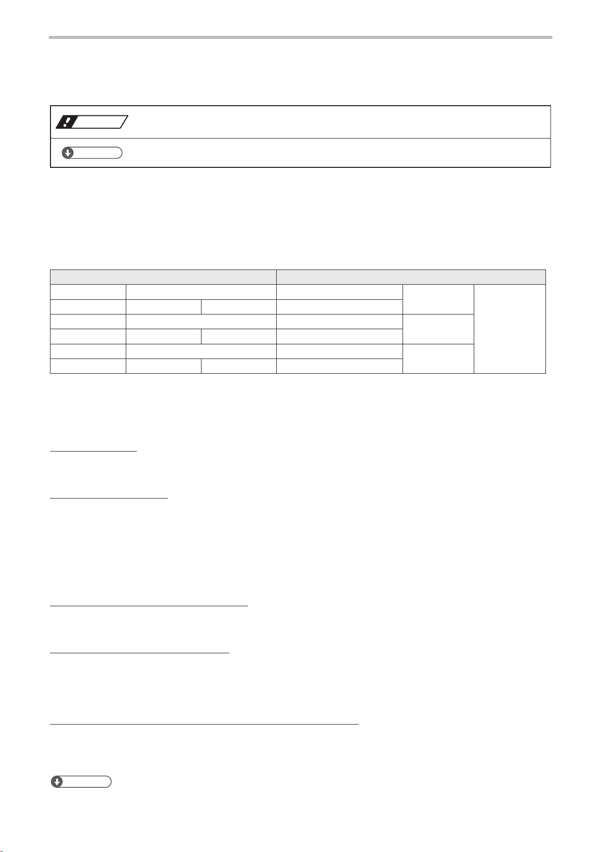
Target model Description in the text
LP-GS 051 LP-GS 051- E LP-GS 051(- E) LP-GS 051 LP-GS Series
LP-GS 051-F LP-GS 051-FE LP-GS 051-FN LP-GS051-F(-FE/-FN)
LP-GS 051- L LP- GS051-L E LP-GS051-L(-LE) LP-G S051-L
LP-GS 051- LF LP-GS 051- LF E LP-GS 051- LF N LP-GS051-LF(-LFE/-LFN)
LP-GS052 LP-GS052-E LP- GS052(- E) LP-GS052
LP-GS052-F LP-GS052-FE LP-GS052-FN LP-GS052-F(-FE/-FN)
Type of manuals
For this product, the following manuals are prepared. Read each manual and operate this product correctly and safely.
Also, save the manuals for future use.
“Reference” denotes any hints for operation, detail explanations, or references.
Laser Safety Guide
This manual describes the items required for using this product correctly and safely. All users shall be required for
reading this manual.
Setup/Maintenance Guide
This manual describes the items required for introduction and installation of this product as well as for the maintenance
work.
• Product specifications, external dimensions
• Installation and connection method
• Signal details, I/O rating, and timing chart when I/O is used for control
• Maintenance details
Mainly the machine builder and system integrator shall be required for reading this manual.
Laser Marker NAVI smart Operation Manual
Instruction manual for the laser marker configuration software “Laser Marker NAVI smart”. This manual describes the
procedure and method to operate the laser marker, and the screen operations to set marking contents.
Serial Communication Command Guide
This manual describes the communication commands to control this product externally using the serial communication
(RS-232C/Ethernet). It describes the communication settings, communication data formats, communication commands,
and the control samples.
Mainly the machine builder and system integrator shall be required for reading this manual.
Serial Communication Command Guide: LP-400/V compatible mode
This manual describes the communication commands to control this product externally using the compatible command
format with the former models of LP-400/LP-V series.
Mainly the machine builder and system integrator shall be required for reading this manual.
ンㄆㄇㄆㄓㄆㄏㄆ
12
• The PDF data of each manual is included on an attached CD-ROM “Laser Marker Smart Utility”.
• To read the PDF manual, Adobe Reader (Version X or later) of Adobe Systems Incorporated is required.

Contents
ME-LPGS-SM-8
Preface ............................................................................................................... 2
Cautions in Handling
Applicable Standards and Related Regulations
How to Read this Document
........................................................................................... 3
.................................................. 9
.............................................................................. 12
1 Product Overview …………………………………………………… 17
1-1 Product Model ............................................................................................. 18
1-2 Product Configuration ................................................................................. 19
1-3 Package ...................................................................................................... 20
1-4 Specification ............................................................................................... 22
1-5 Outer Dimensional Drawing ........................................................................ 24
1- 5 -1 Head .......................................................................................................... 24
1-5-2 Controller ................................................................................................... 25
1-5-3 Cables ....................................................................................................... 26
1-6 Name of Each Component ......................................................................... 27
1- 6 -1 Head .......................................................................................................... 27
1-6-2 Controller ................................................................................................... 29
2 Laser Marker Installation …………………………………………… 32
2-1 Installation Environment .............................................................................. 33
2-2 Installation Space ........................................................................................ 34
2-3 Head Installation ......................................................................................... 35
2-3-1 Installation direction ................................................................................... 35
2-3-2 Installation method .................................................................................... 37
2-3-3 Marking field and marking center position ................................................. 38
2-3-4 Marking position check ............................................................................. 39
2-4 Controller Installation .................................................................................. 40
2-5 Connecting Laser Marker ............................................................................41
2-5-1 Connection of head and controller ............................................................ 41
2-5-2 Power connection and earth (Grounding) .................................................. 42
2-5-3 Connection of PC (Laser marker NAVI smart) .......................................... 44
2-6 Construction of System............................................................................... 47
3 Operation Method…………………………………………………… 48
3-1 Type of Operations ...................................................................................... 49
3-2 Start-up & Termination ............................................................................... 50
3-2-1 Start-up procedure .................................................................................... 50
3-2-2 Termination procedure ............................................................................... 51
13

3-3 Operation by PC Configuration Software ................................................... 52
ME-LPGS-SM-8
3-3-1 Operation procedure ................................................................................. 52
3-3-2 Screen types ............................................................................................. 54
3-3-3 How to establish online connection ........................................................... 56
3-3-4 How to disconnect online connection ........................................................ 58
3-3-5 How to switch screens .............................................................................. 59
3-3-6 Test marking and RUN mode .................................................................... 61
3-4 Operation by External Devices ................................................................... 62
3-4-1 Operation method using external control device ....................................... 62
3-4-2 Operation procedure with external control ................................................ 63
3-4-3 Settings before external control ................................................................ 64
3-4-4 Remote mode settings .............................................................................. 67
4 External Control Using I/O …………………………………………68
4-1 I/O Interface Specification ........................................................................... 69
4-2 Signals and Details of I/O Terminal Block ................................................... 70
4-3 Signals and Details of I/O Connector .......................................................... 78
4-4 I/O Rating/Circuit ........................................................................................ 85
4-4-1 Input rating and input circuit ...................................................................... 85
4-4-2 Output rating and output circuit ................................................................. 86
4-4-3 Interlock terminal rating and I/O circuit ...................................................... 87
4-5 Connecting I/O Terminal Block ................................................................... 88
4-5-1 Factory default wiring ................................................................................ 88
4-5-2 Connecting common terminals.................................................................. 89
4-5-3 Sensor connection example ...................................................................... 90
4-5-4 Connection example of interlock terminals and laser stop terminals ........ 90
4-5-5 Checking the I/O terminal status ............................................................... 91
4-6 Basic Control Timing Chart......................................................................... 92
4-6-1 Flow from startup to marking ..................................................................... 92
4-6-2 Shutter open/close .................................................................................... 94
4-6-3 Marking trigger input: Single trigger .......................................................... 95
4-6-4 Marking trigger input: Continuous trigger .................................................. 96
4-6-5 Guide laser radiation input ........................................................................ 98
4-6-6 Select file .................................................................................................. 99
4-6-7 Time/date hold input and date gap output ................................................ 100
4-6-8 Counter end output .................................................................................. 100
4-6-9 Count-up/count-down value correction .................................................... 101
4-6-10 Counter reset input ................................................................................. 102
4-6-11 Registered characters/external offset marking ....................................... 103
4-6-12 Laser stop 1 input ................................................................................... 104
4-6-13 Laser stop 2 input ................................................................................... 105
4-6-14 Interlock input ......................................................................................... 106
14

5 External Control by Communication Commands …………… 107
ME-LPGS-SM-8
5-1 Serial Communication Interfaces ............................................................... 108
5-2 RS-232C .................................................................................................... 109
5-2-1 Interface specifications and connection ................................................... 109
5-2-2 Communication settings (for command control) ........................................111
5-3 Ethernet ......................................................................................................112
5-3-1 Port specifications and connection ...........................................................112
5-3-2 Communication settings ............................................................................113
5-3-3 Connecting to external control devices and its setting sample .................114
5-4 Checking the communication commands ...................................................115
6 Link Control with External Devices …………………………… 116
6-1 Link Control with Image Checker ................................................................117
6-1-1 Example of image checker linkage system ................................................118
6-1-2 Operation flow ...........................................................................................119
6-1-3 Connection ............................................................................................... 120
6-1-4 Set the laser marker communication settings ........................................... 121
6-1-5 Set the laser marker overall file conditions ............................................... 122
6-1-6 Image checker setting .............................................................................. 125
6-1-7 Code reader (LP-ABR) setting .................................................................. 129
6-1-8 Code reader (DataMan) setting ................................................................ 129
6-1-9 Timing chart .............................................................................................. 130
6-2 Link Control with Code Reader .................................................................. 134
6-2-1 Example of code reader linkage system ................................................... 13 4
6-2-2 Operation flow .......................................................................................... 135
6-2-3 Connection ............................................................................................... 137
6-2-4 Preparation of readout code ..................................................................... 138
6-2-5 Setting of code reader linkage functions .................................................. 139
7 Maintenance ……………………………………………………… 141
7-1 Maintenance Items ......................................................................................142
7-2 Maintenance Details of Parts ..................................................................... 143
7-2-1 Laser emission port (f θ lens) .................................................................... 143
7-2-2 Intake/exhaust vent ................................................................................... 144
7-2-3 Air filter ...................................................................................................... 145
7-2-4 Air-cooling fan ........................................................................................... 146
7-2-5 Laser oscillator .......................................................................................... 150
7-2-6 Galvano scanner....................................................................................... 153
7-2-7 Z-axis adjustment module ......................................................................... 154
7-2-8 Internal shutter .......................................................................................... 154
7-2-9 Replacement of battery inside the controller ............................................ 155
7-2-10 Replacement of fuse ............................................................................... 157
15

7-2-11 Replacement of cable .............................................................................. 157
ME-LPGS-SM-8
7-3 Obtaining Backup Data .............................................................................. 158
7-4 Serial Number Checking Method ............................................................... 159
7-5 Disposal of Laser Marker ........................................................................... 160
7-5-1 Separate disposal of head section ............................................................ 160
7-5-2 Disposal of old equipment and batteries .................................................. 160
Troubleshooting ……………………………………………………… 162
Troubleshooting ................................................................................................ 163
Error Indication
Alarm: E001 - E599 ............................................................................................ 173
Warning: E600 - E799
..................................................................................................173
........................................................................................ 177
Index ………………………………………………………………… 186
16

1 Product Overview
ME-LPGS-SM-8
1-1 Product Model
LP-GS 051 -L F E
qewt
ME-LPGS-SM-8
CO2 Laser Marker LP-GS series have the following models.
Some of the specifications and the packaged contents vary depending on the model. For details, see “1-4 Specification”
(P. 22) and “1-3 Package” (P.20).
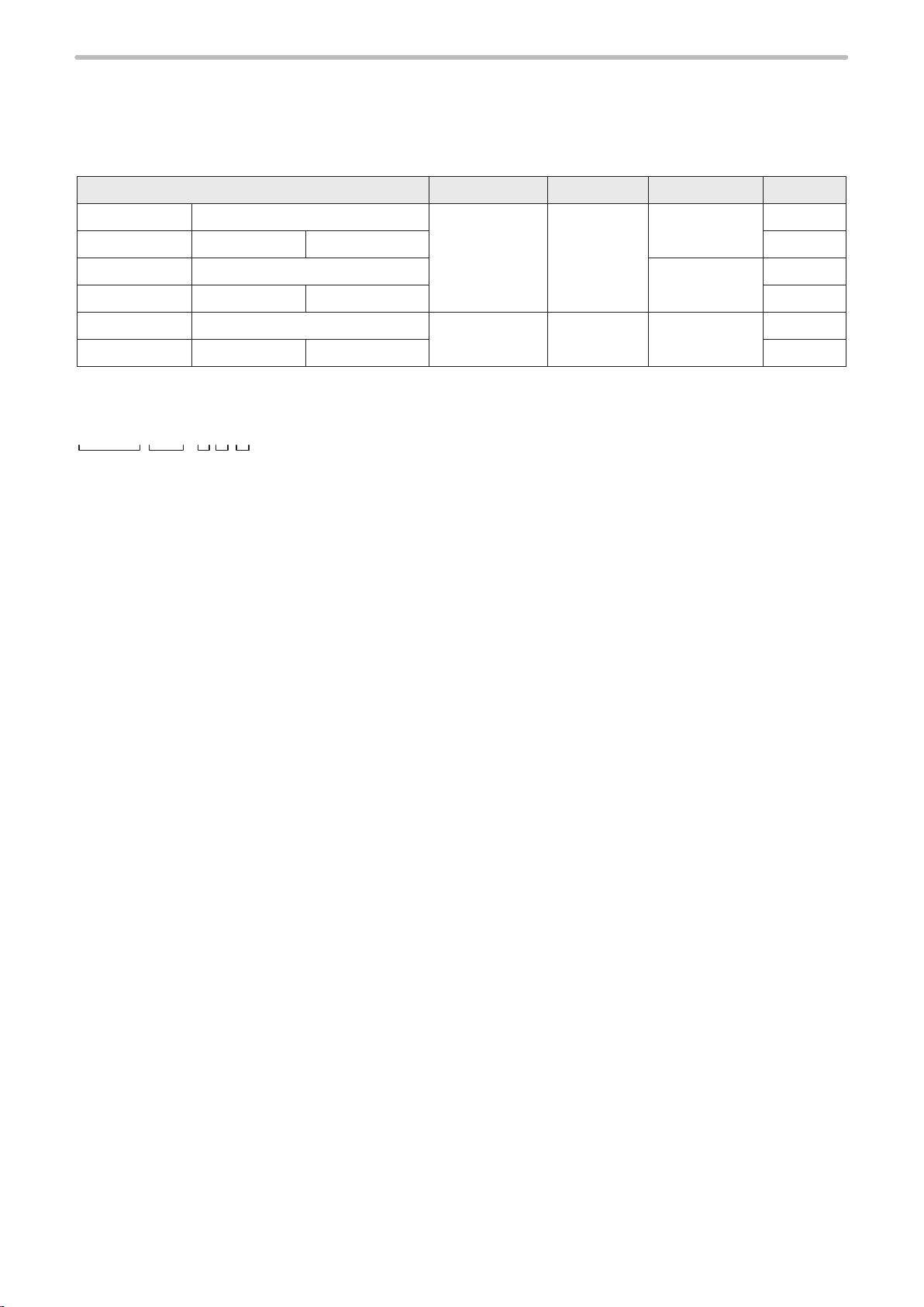
Model Marking field Laser output Z-axis control Bluetooth
LP-GS 051 LP-GS051-E 55 mm x 55 mm 5W Available Available
LP-GS 051-F LP -GS 051- FE LP- GS0 51-FN None
LP-GS 051- L L P- G S051-LE None Available
LP-GS 051- LF LP -GS 051- LFE LP- GS0 51- LFN None
LP-GS052 LP-GS052-E 30 mm x 30 mm 1.3W Available Available
LP-GS052-F LP-GS052-FE LP-GS052-FN None
Model description
r
Represents the series name. “LP-GS series” refers to the CO2 laser marker.
q
Represents the laser output class and the marking field size. The following types are applicable to this product.
w
051: Laser output 5W, Marking field 55 mm x 55 mm
052: Laser output 1.3W, Marking field 30 mm x 30 mm
Represents the existence of the Z-axis control function.
e
None (Left justified): A model with the Z-axis control function.
-L: A model without the Z-axis control function.
Represents the existence of the Bluetooth function.
r
None (Left justified): A model with the Bluetooth function.
-F: A model without the Bluetooth function.
If the model ends with “E” or “N”, it indicates the specifications of the attached AC power cable.
t
-E: Attaches the rating 250V and VDE standards compatible AC cable (For Europe)
-N: Attaches the rating 250V and CCC standards compatible AC cable (For China)
None: Attaches the rating 125V, and PSE standards and CSA/UL standards compatible AC cable
(For North America and Japan)
18
1-2 Product Configuration
u
ME-LPGS-SM-8
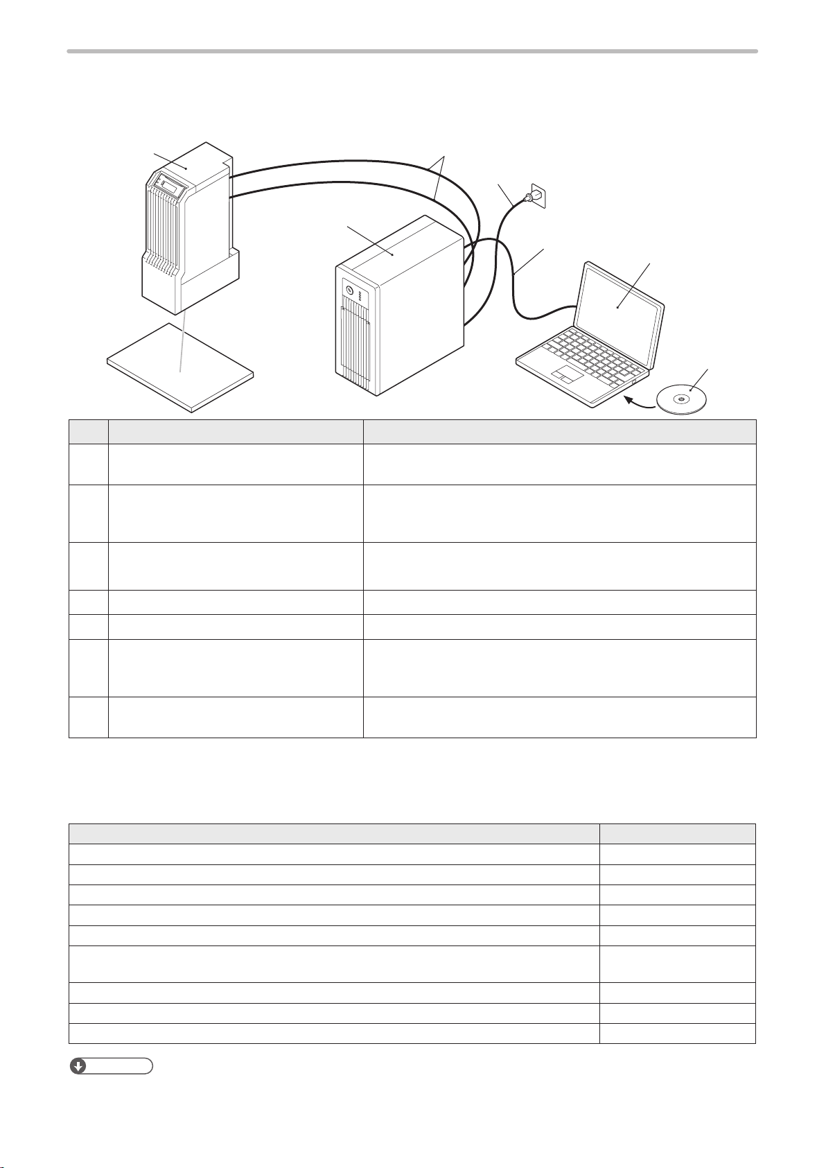
This product is a laser marker designed to mark and process the object by radiating a laser beam to the target.
The laser marker LP-GS series mainly consists of the following devices:
q
e
r
w
t
ABCD
No. Name Description
Head It is the unit that radiates the laser beam. The laser oscillator, the
q
optical parts and the scanner are loaded inside.
Controller It is the unit that generates the marking data. The main power
w
supply of the laser marker and connection interface with external
devices are loaded.
y
Unit power cable (Attached accessory)
e
Signal cable (Attached accessory)
AC power cable (Attached accessory) Cable to supply AC power to the controller.
r
USB cable (Attached accessory) Cable to connect the laser marker with a PC.
t
Commercially available PC
y
(Not included in this product.)
Laser Marker Smart Utility software
u
(Attached CD -ROM)
Optional items
The following optional items (sold separately) are available for this product.
For purchasing and the detailed information, please contact our sales office.
Optional items Model
Air filter (for replacement) LP-AFT70
Head fan (for replacement) LP- A FA10
Controller fan (for replacement) LP- A FA11
Unit power cable (for replacement) LP-ACP10 -5
Signal cable (for replacement) LP- ACS10-5
AC power cable (for replacement): Rating 125V, PSE and CSA/UL standards compatible
cable (North America, Japan)
AC power cable: Rating 250V, PSE standards compatible cable (Japan) LP-ACA11
AC power cable (for replacement): Rating 250V, VDE standards compatible cable (Europe) LP-ACA12
Battery inside the controller (for replacement) AFPX- BATT (CR -24 50)
Cables to connect the head and controller.
Install the attached software “Laser Marker Smart Utility” onto a PC
and set the marking data of the laser marker. You can use this PC
as a monitor during the operation.
This software contains the laser marker configuration software
“Laser Marker NAVI smart” and PDF manual data.
LP-ACA10
ンㄆㄇㄆㄓㄆㄏㄆ
• For the recommended AC power cable for China (rating 250V, CCC standards compatible cable), please contact our
sales office.
19
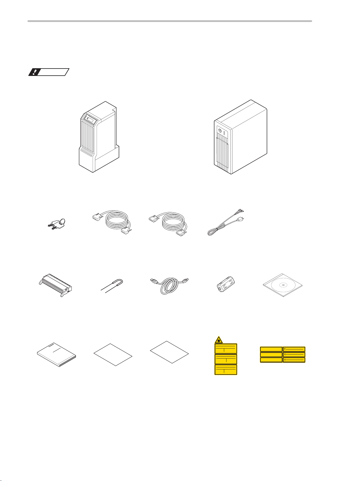
1-3 Package
ワㄐㄕㄊㄆ
ME-LPGS-SM-8
Before using this product, be sure to check the packed objects as shown below.
This product is delivered in a set of head unit and controller unit packed in one box.
If you find any missing item in the package, please contact the dealer you purchased it or our sales office.
• Be sure to store the packing material. Since this product is precision machinery, reuse the packing materials to prevent
damages during transportation.
Laser marker head
□
1 unit
Laser marker controller
□
1 unit
System key
□
qt y.: 2 qt y.: 1
I/O terminal block
□
qt y.: 1 qt y.: 6
Laser Safety Guide
□
qt y.: 1 qt y.: 1 qt y.: 1 qt y.: 1 qt y.: 1
Unit power cable
□
Short bar
□
(Attached to the I/O
terminal block)
Leaflet of carrying
□
caution and information
about PDF manuals
Signal cable
□
□
qt y.: 1
USB cable (2m)
qt y.: 1 qty.: 1 *2
General information
□
for safety (For EU
user s)
AC power cable *1
□
qt y.: 1
Ferrite core
□
Warning/explanation
□
label
Laser Marker Smart
□
Utility (CD-ROM) *3
qt y.: 1
Aperture label
□
20
*1: Attached AC power cable varies depending on each model. Please select a cable suitable for the standards in the
ME-LPGS-SM-8
country or region where it is used.
• LP-GS051(-L/-F/-LF)/LP-GS052(-F) : Attaches the PSE standards and CSA/UL standards compatible cable (rating
125V).
• LP-GS051-(L/F/LF)E/LP-GS052-(F)E : Attaches the VDE standards compatible cable (rating 250V).
• LP-GS051-(L)FN/LP-GS052-FN : Attaches the CCC standards compatible cable (rating 250V).
*2: Attach the ferrite core to the LAN cable.
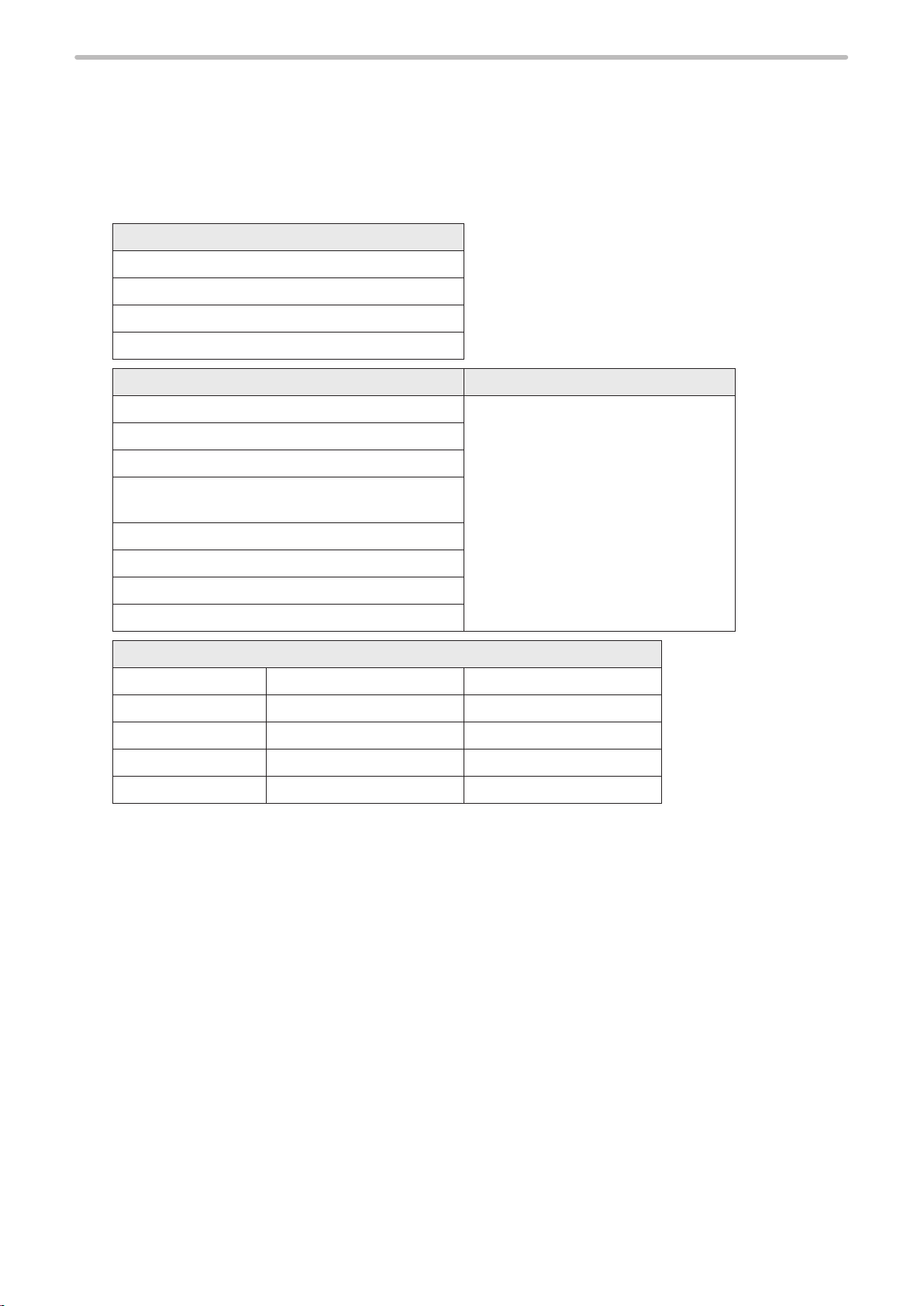
*3: This CD-ROM contains the following data:
PC configuration software
Laser Marker NAVI smart
Logo Data Editing Software
ExportVec
Font Maker
PDF manuals Language
Laser Safety Guide English / Simplified Chinese / Japanese
Setup/Maintenance Guide
Serial Communication Command Guide
Serial Communication Command Guide: LP-400/V
compatible mode
Laser Marker NAVI smart Operation Manual
Logo Data Editing Software Operation Manual
ExportVec Operation Manual
Font Maker Operation Manual
Font data
Original 1 font Original 1 (small) font GB 2312 level-1 font
Original 2 font Original 2 (small) font GB 2312 level-2 font
Original 3 font Original 3 (small) font 2D code pattern font
Original 4 font JIS level-1 font OCR1 font
Original 5 font JIS level-2 font User defined font
21
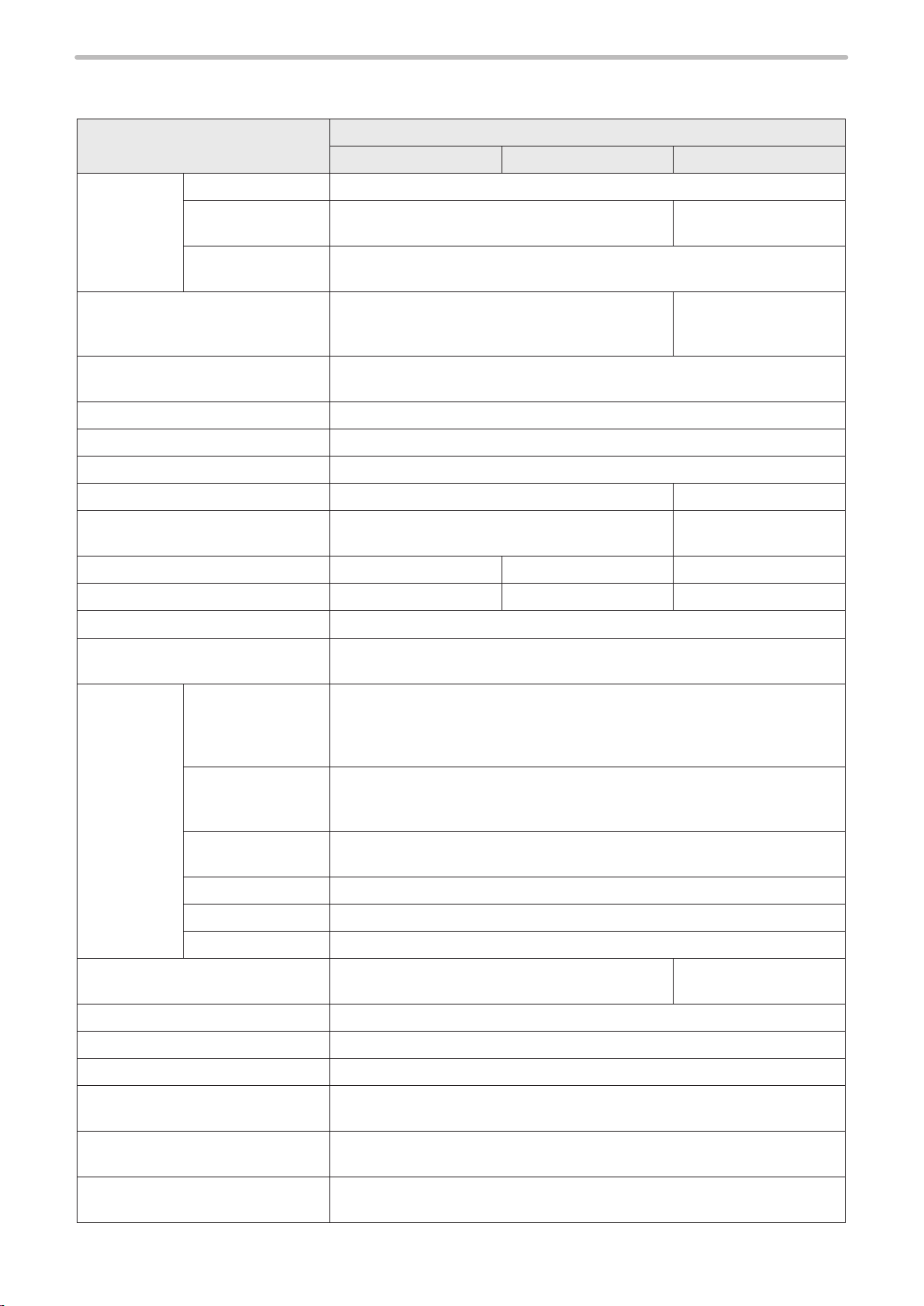
1-4 Specification
ME-LPGS-SM-8
Item
Laser type CO
Average output for
Marking laser
Laser pointer
Scanning system Galvano scanner
Work piece status Stationary object
Marking field (X, Y) [mm]
Work distance (Base position) [mm]
Setting range of work distance [mm] 108 to 114 ― 69.5 to 72.5
processing *1
Laser oscillation
method
Guide laser
Beam stop One shutter is equipped inside of head
*2
LP-GS 051 LP- GS0 51-L LP-GS052
laser, Wavelength: 10,600nm, Class 4 laser
2
5W 1.3W
Red semiconductor, Wavelength: 655nm,
Class 2 laser
Max. output: 1mW or less
Red semiconductor, Wavelength: 655nm, Class 2 laser
Max. output: 1mW or less
55 × 55 30 × 30
111 71
Model
CW Oscillation
None
Scan speed [mm/sec.] *3 Max 3000 Max 2000 Max 3000
No. of setting files 10,000 files
No. of marking data pieces
(No. of registerable objects)
Capital and small letter of alphabet, numeric, symbol, user defined characters
Character
Bar code
Marking
object type
2D code
Graphic data *4 VEC, DXF, HPGL, BMP, JPEG, AI, EPS
TrueTyp e TrueType fonts stored in the PC with Laser Marker NAVI smart installed *5
Data for processing Point radiation
Character height/width [mm] *3
(0.001mm unit)
Character arrangement Straight line, Arc, Proportional, Justify
I/O port I/O terminal block (40-pins), I/O connector (40-pins)
Japanese characters: Katakana, Hiragana, Kanji (JIS level-1 and level-2)
Simplified Chinese characters: GB 2312 level-1 and level-2
CODE39, CODE93, CODE128 (GS1-128), ITF, NW-7, EAN/UPC/JAN
GS1 DataBar Limited CC-A, GS1 DataBar Stacked CC-A
(up to 50 characters can be set)
GS1 DataBar Limited, GS1 DataBar Stacked,
QR Codes, Micro QR Codes, iQR Codes,
Data Matrix, GS1 Data Matrix, PDF417
0.1 to 55 0.06 to 30
2000 pcs./file
22
Serial communication interface EIA-RS-232C, Ethernet
Attached software
Supported OS *6
Laser Marker NAVI smart connection
method
Laser Marker NAVI smart, Logo Data Editing Software,
ExportVec, Font Maker
Windows
®
10 Pro 32bit, 64bit / Windows® 8.1 Pro 32bit, 64bit /
Windows
®
7 Professional SP1 32bit, 64bit
USB, Ethernet, Bluetooth *7
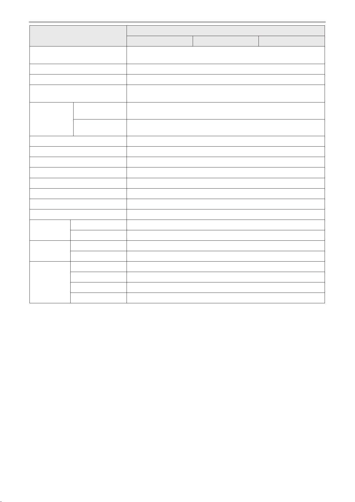
Item
ME-LPGS-SM-8
Model
LP-GS 051 LP- GS0 51-L LP-GS052
Laser Marker NAVI smart display
language
English, German, Simplified Chinese, Traditional Chinese, Japanese, Korean
Required time for system startup Approx. 10 seconds
Required time for laser pumping Approx. 8 seconds to Max. 15 seconds
90V to 132V AC or 180V to 264V AC (including ±10% voltage fluctuations) *8
Frequency: 50/60Hz
Power
Power voltage
100V AC 370VA or less (4.2A or less)
consumption
(Consumption
cur rent) *9
200V AC 500VA or less (2.8A or less)
Grounding method Direct earth for both the head and the controller
Cooling method Forced cooling for both the head and the controller
Operating ambient temperature *10 0°C to +40°C
Ambient temperature for storage *10 -10°C to +60°C
Operating ambient humidity *10 35 to 85%RH
Overvoltage category
Ⅱ
Pollution degree 2
Use location Indoor; at an altitude of 1000 m or below
Installation
direction
Head In all directions
Controller Vertically or horizontally
Head Approx. 11kg
Weight
Controller Approx. 8.0kg
Type Manganese dioxide lithium primary battery
Battery
Model AFPX- BATT (CR -24 50)
(mounted in
product)
Quantity 1 piece
Weight Approx. 7.0g
*1: Average output power from the laser marker at delivery time with the maximum laser power setting.
*2: The work distance base position has approx. +/-0.5mm deviation per product.
*3: The value shown here is the configuration range that can be input. The setting values that can keep the quality of
marking or processing vary depending on the setting details and the target materials.
*4: VEC is a graphic file format dedicated for the laser marker. To use AI or EPS files, convert them to VEC format with the
attached software “ExportVEC”.
*5: Some of the languages or character types are not supported by this laser marker. Characters written from right to left
such as Arabic or Hebrew, characters based on ligature such as Indian languages cannot be input.
*6: OS versions of which Microsoft has ended support are excluded.
*7: The Bluetooth function is not available with the models ending with “-F”. For the Bluetooth specifications, refer to
“Connection type” (P.45).
*8: The power supply voltage switches automatically.
*9: The typical value of the inrush current at startup is as follows: (Duration time is 10ms or less.)
At 100V AC: 60A
At 200V AC: 120A
*10: Common to the controller and the head. No condensation or freezing shall be allowed. If there is a gap between the
stored temperature and operating temperature, make sure to have the product get used to the operating ambient
temperature gradually prior to use to prevent the dew condensation.
23
1-5 Outer Dimensional Drawing
ME-LPGS-SM-8
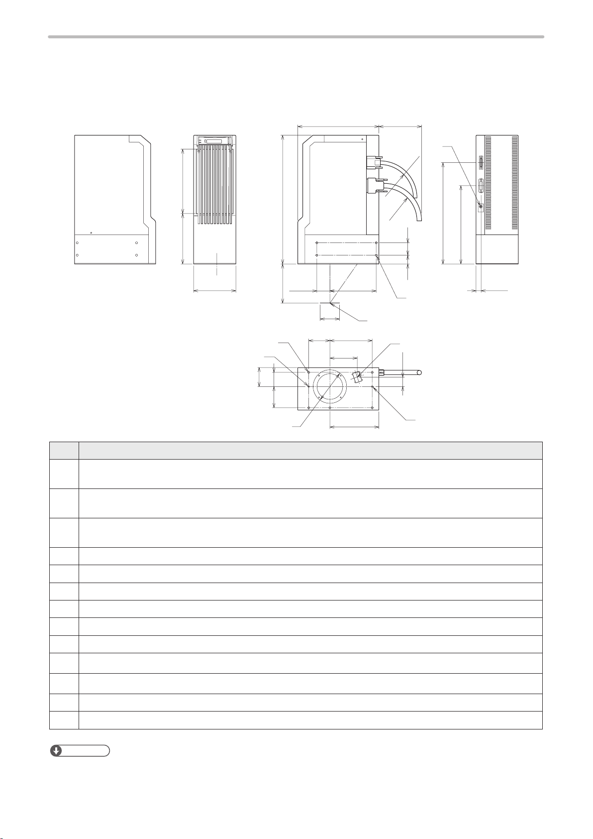
1- 5 -1 Head
Unit: mm
183143
120
e
1)
4060
365
q
o
37
w
131.5
12060
r
y
(125)230
R100
1@
i
t
R100
35
25
1#
(287)
(222)
(15)
u
No. Description
Work distance (base position):
q
LP-GS051/LP-GS051-L: 111 mm, LP-GS052: 71 mm
Marking field (X, Y):
w
LP-GS051/LP-GS051-L: 55 mm x 55 mm, LP-GS052: 30 mm x 30 mm
Center of marking field:
e
LP-GS051/LP-GS051-L: 54 mm, LP-GS052: 50.5 mm
LP-GS051 / LP-GS051-L: 77.5 mm, LP-GS052: 69.5 mm
r
LP-GS051 / LP-GS051-L: 27 mm, LP-GS052: 24 mm
t
Center of marking field
y
Laser emission port diameter: φ94 mm
u
Laser pointer emission port (Emission port diameter: φ20 mm, pointed to the center of marking field)
i
Head fixing screw hole (five holes): M6 screw, depth 6
o
1)
Head positioning pin hole: φ4
1!
Head positioning pin hole: Elongated hole φ4
Head fixing screw hole (both sides at four holes each): M6 screw, depth 11
1@
Screw for frame ground: M4 screw, depth 5
1#
+0.012
0
, depth 5
+0.05
×5, depth 5
0
139
1!
24
ンㄆㄇㄆㄓㄆㄏㄆ
• For details on the head installation, refer to “2-3-2 Installation method” (P.37).
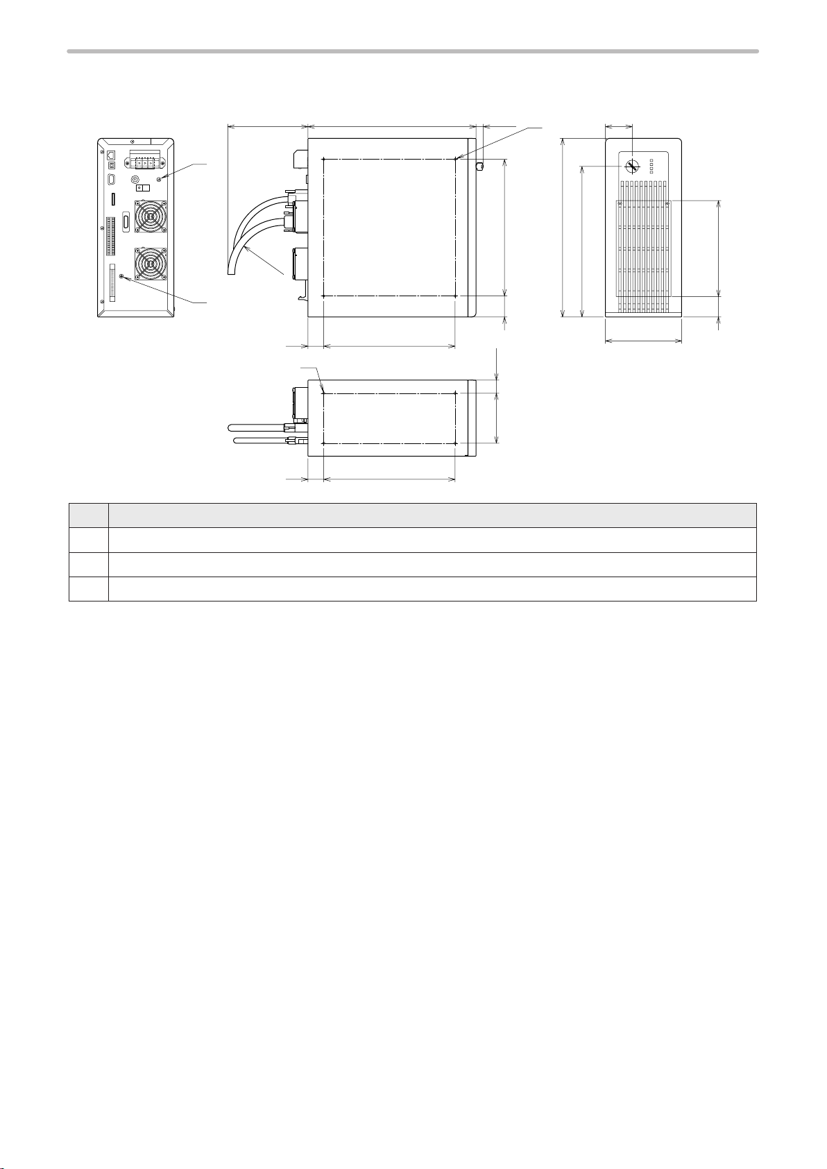
1-5-2 Controller
(155) 320 (25)
(51)
ME-LPGS-SM-8
Unit: mm
w
q
No. Description
Controller fixing screw hole (four holes each on the bottom and the left side on the front): M5 screw, depth 6
q
Protective conductor terminal: M4 screw, depth 5
w
Screw for frame ground: M4 screw, depth 5
e
e
R100
30
30
q
250
250
95 25
40 260
340
(287)
39 183
145
25
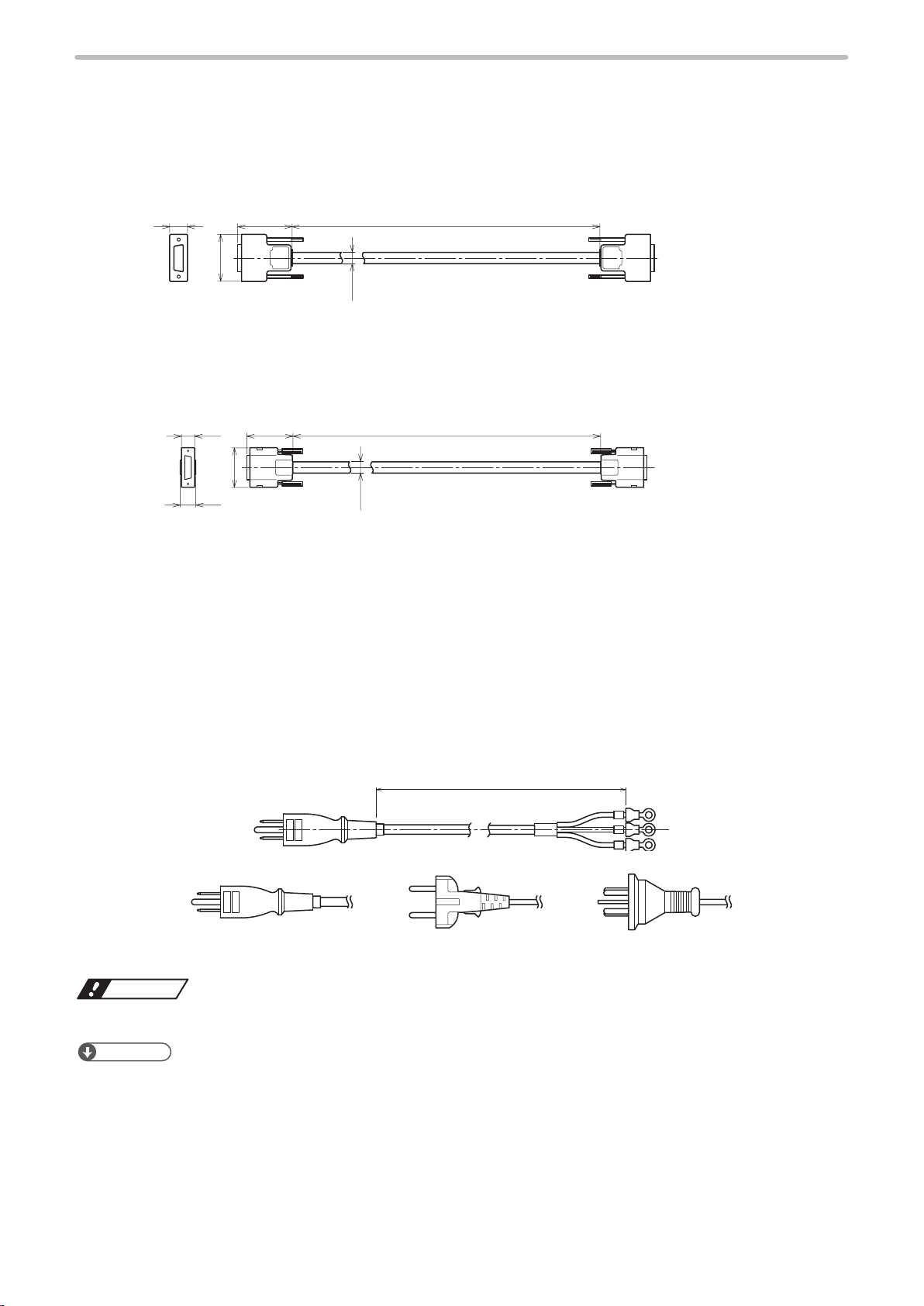
1-5-3 Cables
+200
+200
3000±100
qwe
ワㄐㄕㄊㄆ
ME-LPGS-SM-8
Unit power cable
Unit: mm
Minimum bent radius 100mm
Flex-resistant cable
43
Signal cable
Unit: mm
Minimum bent radius 100mm
Flex-resistant cable
36
14
5000
5000
0
0
4916
9
ȭ
4212
8
ȭ
AC power cable
Attached AC power cable varies depending on each model. Select a cable suitable for the standards in the country or
region where it is used.
Rating 125V, PSE standards and CSA/UL standards compatible cable (North America, Japan): Included in LP-GS051(-
q
L/-F/-LF)/LP-GS052(-F)
Rating 250V, VDE standards compatible cable (Europe): Included in LP-GS051-(L/F/LF)E / LP-GS052-(F)E
w
Rating 250V, CCC standards compatible cable (China): Included in LP-GS051-(L)FN / LP-GS052-FN
e
Unit: mm
Minimum bent radius 50mm
26
• Be sure to connect the ground pin of the AC power cable to earth permanently.
ンㄆㄇㄆㄓㄆㄏㄆ
• AC power cable with Rating 250V approved PES standard is available as option items (LP-ACA11). For details, please
contact our sales office.
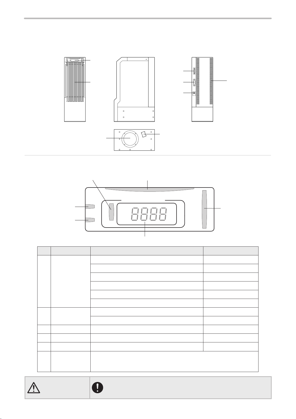
1-6 Name of Each Component
1
8
e
r
y
q
WARNING
ME-LPGS-SM-8
1- 6 -1 Head
2
7
5
1. Head display panel
The display that shows the status of laser radiation and the laser marker.
tw
ョリロユチワㄐハチバチユンンヰンチヤヰュユチ
ンユヮヰヵユチ
モロモンヮチ
ワヰヵリヤユチ
ヸモンワリワヨチ
3
4
6
ヱヤノロリワレチ
ロモヴユンチ
ヴラヶヵヵユンチ
ヮモンレリワヨチ
No. Display name Status Indication
LASER
q
SHUTTER
MARKING
ALARM
w
WARNING
REMOTE Remote mode (operation by external control) state Green lighted-up
e
NOTICE This indicator is non-operational. (system reserved) -
r
PC-LINK Connected to Laser Marker NAVI smart online Green lighted-up
t
FILE No./
y
ERROR CODE
Radiating the laser Orange lighted-up
Laser pumping state/Shutter OPEN Green lighted-up
Laser pumping state/Shutter CLOSE White lighted-up
Laser pumping uncompleted/Shutter OPEN Green flashing
Laser pumping uncompleted/Shutter CLOSE White flashing
Laser non-pumping status Lights off
Alarm Red lighted-up
Warning Yellow lighted-up
Normal: Displays the file number selected
Error: Displays the error code (See P.173)
Start-up: Displays software version of the controller
• If the laser emission indicator is placed out of the sight of operators, place
the external indicator light or warning lamp on the immediately apparent
place on the system.
27

2. Signal connector: SIGNAL
ME-LPGS-SM-8
This is the terminal for communicating between head and controller.
Connect the attached signal cable.
3. Power connector: POWER
This is the connector for supplying the power to the head.
Connect the attached unit power cable.
4. Frame ground terminal: F.G.
This is the terminal for ground. Ground this terminal to the earth permanently.
5. Laser emission port
The emission port of the marking laser and the guide laser for LP-GS051(-L).
6. Laser pointer emission port
From this port the red laser pointer radiates in oblique direction for the guide pointer function. The pointer radiates
also when using the work distance indication by the guide laser for LP-GS051(-L). Refer to “2-3-4 Marking position
c h e c k ” ( P. 39).
To use these guide laser functions, do not seal the laser pointer emission port at the installation.
7. Head air-cooling inlet
The air-cooling inlet for the head. Fans and a filter are installed.
8. Head air-cooling outlet
The air-cooling outlet for the head.
28
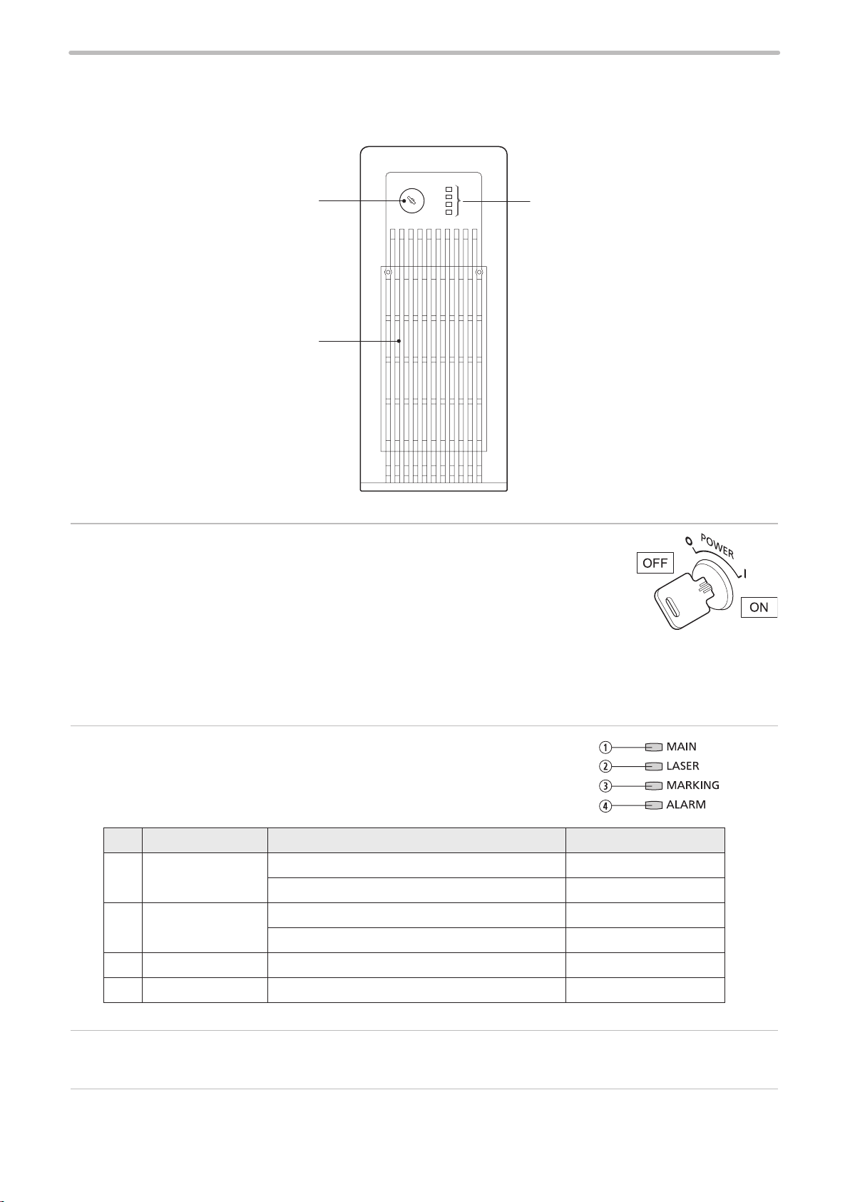
1-6-2 Controller
12
ME-LPGS-SM-8
Front
3
1. Key switch: POWER
The main power switch for the laser marker.
Turn ON ( | ) the key switch to start-up the system, and turn OFF ( ○ ) to shutdown the
system.
Only when the key switch is turned OFF (in O position), the key can be pulled out.
When the laser marker is not in use, the key should be in safekeeping by a laser safety
manager.
In case of turning ON the power supply after turning OFF, leave the interval five seconds or more between ON and
OFF.
Do not turn off the power supply while the system starts (during MAIN indicator is flashing).
2. Controller indicator
The indicator that shows the status of the laser marker.
No. Display name Status Indication
MAIN System startup state Green lighted-up
q
System starting up (not completed) Green flashing
LASER Laser pumping status White lighted-up
w
Laser pumping (not completed) White flashing
MARKING Radiating the laser Orange lighted-up
e
ALARM Alarm Red lighted-up
r
3. Controller air-cooling inlet
The air inlet for cooling the controller. The air filter is installed.
29
6
7
5
4
3
19
10
11
12
13
2
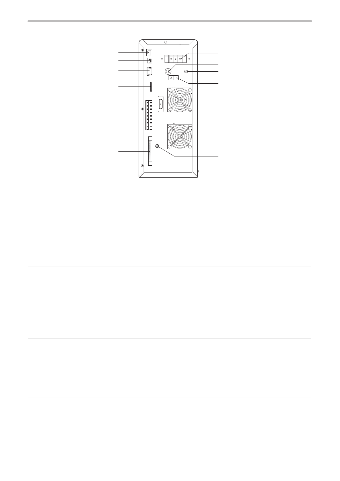
ME-LPGS-SM-8
Rear
8
1. Ethernet port: LAN
The port to connect the LAN cable used when connecting the laser marker with the following devices via Ethernet.
• The PC with Laser Marker NAVI smart installed
• PLC or PC for control: Externally controls the laser marker using the communication commands.
• Specified external devices: Interfaces the specified external device (image reading equipment) with the laser marker
and controls their operations.
2. USB port B: USB
This is the connector for connecting the attached USB cable. When you connect the laser marker configuration
software Laser Marker NAVI smart online, connect this cable to the PC.
3. RS-232C port: RS-232C
The port to connect the following external devices for the serial communication control of the laser marker using RS232C.
• PLC or PC for control: Externally controls the laser marker using the communication commands.
• Code reader compatible with the RS-232C communication: Modifies the data to mark by the laser marker according
to the code details read by the code reader.
4. Signal connector: SIGNAL
This is the terminal for communicating between head and controller. Connect the attached signal cable.
5. Power connector: POWER
This is the connector for supplying the power to the head. Connect the attached unit power cable.
6. I/O terminal block: TERMINAL
The terminal block to connect I/O signals used for the external control of the laser marker.
Connect the attached terminal block.
Refer to “4-2 Signals and Details of I/O Terminal Block” (P.70) for details.
30
7. I/O connector: I/O
The connector to connect I/O signals used for the external control of the laser marker.
For details, refer to “4-3 Signals and Details of I/O Connector” (P.78).
 Loading...