

Panasonic LP-ABR11, LP-ABR12, LP-ABR10-C5, LP-ABR10-L5 Setup And Operation Manual

Code Reader
Setup /
Operation Manual
LP-ABR10 Series
ME-LPABR10-SO-3
2016.12
panasonic.net/id/pidsx/global
Please read these instructions carefully before using this product,
and save this manual for future use.

Preface
WARNING
CAUTION
Thank you for purchasing our product.
For full use of this product safely and properly, please read this manual carefully.
This product has been strictly checked and tested prior to its delivery. However, please make sure that this product
operates properly before using it. In case that the product becomes damaged or does not operate as specied in this
manual, contact the dealer you purchased from or our sales ofce.
General terms and conditions of this manual
1. Before using this product, or before every starting operation, please conrm the correct functioning and performance
of this product.
2. Contents of this manual could be changed without notice.
3. This manual must not be partially or totally copied or revised.
4. All efforts have been made to ensure the accuracy of all information in this manual. If there are any questions,
mistakes, or comments in this manual, please notify us.
5. Please remind that we assume no liability for any results arising out of operations regardless of the above clauses.
Disclaimer
The applications described in this manual are all intended for examples only. The purchase of our products described in
this manual shall not be regarded as granting of a license to use our products in the described applications. We do NOT
warrant that we have obtained some intellectual properties, such as patent rights, with respect to such applications, or that
the described application may not infringe any intellectual property rights, such as patent rights, of a third party.
Trademark
• Windows is a registered trademark or trademark of Microsoft Corporation in the United States and/or other countries.
• All other product names and companies provided in this manual are trademarks or registered trademarks of their
respective companies.
Cautions in Handling
To reduce the risk of injury, loss of life, electric shock, re, malfunction, and damage to equipment or property, always
observe the following safety precautions.
The following symbols are used to classify and describe the level of hazard, injury, and property damage caused when the
denotation is disregarded and improper use is performed.
Denotes a potential hazard that could result in serious injury or death.
Denotes a hazard that could result in minor injury.
The following symbols are used to classify and describe the type of instructions to be observed.
This symbol is used to alert users to a specic operating procedure that must not be performed.
ALWAYS FOLLOW THESE IMPORTANT
SAFETY PRECAUTIONS!
This symbols is used to alert users to a specic operating procedure that must be followed in order to
operate the unit safely.
This symbols is used to alert users to a specic operating procedure that must be performed carefully.
2

Safety notices
WARNING
This product is intended for us e in g eneral electronics equipment ( electronic
computer, OA equipment, communications equipment, test and measurement
equipment, machine too ls, industrial robots, AV equipm ent , home appliances etc.).
Appropriate measures should be taken at use of unit/syst em rel at ed t o s afety and
operation of transportat ion equi pment ( airc raft, t rain, auto mobi le), t raffic s ignal, gas
leak detector and safety devices.
This product is not design ed or intended for the use as a component in life support
appliances or as surgical i mp lants nor in any other application where failure of the
product could cause personal injury or death. The use of this product shall
indemnify and hold har mless t o Panasonic Industrial Devices SU NX 's and its
shareholders against any claims of injury or death associated w it h unintended
authorized use.
DO NOT disassemble. Di s assembly will void the warranty and could cause
damage or personal injury .
Avoid the following locations that could cause an accident or damage to the
product.
- Exposed to ambient tem perature outside the rating
- Exposed to relative hum idity outside the rating
- Exposed to rapid temper ature fluctuations (causing condensation)
- Exposed to direct sunl ight or near heaters
- Exposed to direct vibration or shock
- In the presence of dust, salt, or iron particles
- In environments where st atic electricity can build into siginificant charges
- In the presence of flamma ble or explosive gases
- In the presence of corrosive gas
3

Handle with care
This product has a me m ory backup function. This backup data restoration cannot
be guaranteed if repair, reconstruct ion, or upgrade s are perform ed on this product.
DO NOT use this product at temperature or humidity ranges beyond that
documented in the produc t s peci fi cat ions, or in direct sunlight.
DO NOT expose thi s pr oduct to water, moisture, oil, etc.
This product may be damaged in environments containing corrosive gas.
DO NOT use any chemicals when cleaning.
To clean the read ing w i ndow, wipe lightly with cloth or swab.
This is a high-precision optical device, avoid exposing this product to exces sive
force such as that sustain ed by a drop.
Do not install electr i cal wiring or plugin/unplug of cable (except LAN cable) when
this product is powered on. These may result in an electrical damage to this
product.
To minimize the r isk of d ata los s, ma ke sur e to bac kup t he hard drive be fore ins ta ll
the software. Our compan y shall not be responsible for any troubles such as data
loss or damages.
If this product is installed near the laser marker, make sure that it is installed i n the
place where laser beam and its r ef le c t ed beam do not damage to this product.
Store away fro m d irect sunlight and direct vibration or shock for long term storage.
Do not store this product at t emp er at ur e or humidity ranges beyond that
documented in the produc t s peci fi cat ions.
4

General Terms and Conditions
Although we are striving to improve quality and reliability of our products, failure in electric components and
devices may happen with a certain probability. It is hig hly reco mmended t o employ f ail-saf e desig ns, inc ludin g
redundant design, flame propagation prevention design, and malfunction prevention design, as well as
periodical maintenance to avoid any risk of bodily injury, fire accident, or social damage due to any failure of
our products.
Please read carefully a nd accept the following “ Ca ut io ns for Safe Use” and “Warranty Policy” before us ing o ur
products.
1. PRODUCT MODIFICATIONS & DISCONTINUANCE:
Panasonic Industrial Devices SUNX expressly reserves the right to modify, including the right to
discontinue, any of the Products, prior to their order, from time to time without notice.
2. WARRANTIES:
(1) Subject to the exclusions stated in 3 (EXCLUSIONS) herein below, Panasonic Industrial Devices
SUNX warrants the Products to be free of defects in material and workmanship for a period of one
(1) year from the date of shipment under normal usage in environments commonly found in
manufacturing industry.
(2) Any Products found to be defective mu st be shipped to Panasonic Industrial Devices SUNX with all
shipping costs paid by Purchaser for inspection and examination. Upon examination by Panasonic
Industrial Devices SUNX, Panasonic Industrial Devices SUNX will, at its sole discretion, repair or
replace at no charge, or refund the purchaser price of, any Products found to be defective.
3. EXCLUSIONS:
(1) This warranty does not apply to defects resulting from any cause:
(i) which was due to abuse, misuse, mishandling, improper installation, improper interfacing, or
improper repair by Purchaser;
(ii) which was due to unauthorized modification by Purchaser, in part or in whole, whether in
structure, performance or specification;
(iii) which was not discoverable by a person with the state-of-the-art scientific and technical
knowledge at the time of manufacture;
(iv) which was due to an operation or use by Purchaser outside of the limits of operation or
environment specified by Panasonic Industrial Devices SUNX;
(v) which was due to Force Majeure; and
(vi) which was due to any use or application expressly discouraged by Panasonic Industrial
Devices SUNX in 5 (CAUTIONS FOR SAFE USE) hereunder.
(2) This warranty extends only to the first purchaser for application, and is not transferable to any
person or entity which purchased from such purchaser for application.
4. DISCLAIMERS:
(1) Panasonic Industrial Devices SUNX’s sole obligation and liability under this warranty is limited to
the repair or replacement, or refund of the purchase price, of a defective Product, at Panasonic
Industrial Devices SUNX’s option.
(2) THE REPAIR, REPLACEMENT, OR REFUND IS THE EXCLUSIVE REMEDY OF THE
PURCHASER, AND ALL OTHER WARRANTIES, EXPRESS OR IMPLIED, INCLUDING,
WITHOUT LIMITATION, THE WARRANTIES OF MERCHANTABILITY, FITNESS FOR A
PARTICULAR PURPOSE, AND NON-INFRINGEMENT OF PROPRIETARY RIGHTS, ARE
HEREBY EXPRESSLY DISCLAIMED. IN NO EVENT SHALL PANASONI C INDUSTRIAL
DEVICES SUNX AND ITS AFFILIATED ENTITIES BE LIABLE FOR DAMAGES IN EXCESS OF
THE PURCHASE PRICE OF THE PRODUCTS, OR FOR ANY INDIREC T, INCIDENTAL,
SPECIAL OR CONSEQUENTIAL DAMAGES OF ANY KIND, OR ANY DAMAGES RESULTING
FROM LOSS OF USE, BUSINESS INTERRUPTION, LOSS OF INFORMATION, LOSS OR
INACCURACY OF DATA, LOSS OF PROFITS, LOSS OF SAVINGS, THE COST OF
PROCUREMENT OF SUBSTITUTED GOODS, SERVICES OR TECHNOLOGIES, OR FOR ANY
MATTER ARISING OUT OF OR IN CONNECTION WITH THE USE OR INABILITY TO USE THE
PRODUCTS.
5

5. CAUTIONS FOR SAFE USE:
(1) It is Purchaser’s sole responsibility to ascertain the fitness and suitability of the Products for any
particular application, as well as to abide by Purchaser’s applicable local laws and regulations, if
any.
(2) In incorporating the Products to any equipment, facilities or systems, it is highly recommended to
employ fail-safe designs, including but not limited to a redundant design, flame propagation
prevention design, and malfunction prevention design so as not to cause any risk of bodily injury,
fire accident, or social damage due to any failure of such equipment, facilities or systems,
(3) The Products are each intended for use only in environments commonly found in manufacturing
industry, and, unless expressly allowed in this ma nua l, specification or otherw ise, sha ll n ot b e us e d
in, or incorporated into, any equipment, facilities or systems, such as those:
(i) which are used for the protection of human life or body parts;
(ii) which are used outdoors or in environments subject to any likelihood of chemical
contamination or electromagnetic influence;
(iii) which are likely to be used beyond the limits of operations or environments specified by
Panasonic Industrial Devices SUNX in this manual or otherwise;
(iv) which may cause risk to life or property, such as nuclear energy control equipment,
transportation equipment whether on rail or land, or in air or at sea, and medical equipment;
(v) which otherwise require a high level of safety performance similar to that required in those
equipment, facilities or systems as listed in (i) through (iv) above.
6. EXPORT CONTROL LAWS:
In some jurisdictions, the Products may be subject to local export laws and regulations. If any diversion
or re-export is to be made,
Purchaser is advised to abide by such local export laws and regulations, if any, at its own responsibility.
7. PURCHASER’S TRANSFER OBLIGATIONS:
If Purchaser resell or del iv er th e Pr od uct s t o a t h ird par ty , Purchaser must provide s uch th ir d party with a
copy of this document, all specifications, manuals, catalogs, leaflets and written information of any kind
provided to Purchaser by Pan ason ic In dus tria l D ev ices SUNX or its authorized local repre s ent at iv e from
time to time regarding t he Pro ducts. If Pur chaser r esell or del iv er the Produ cts to a third party, Purcha ser
must provide such third party with a copy of this document, all specificati ons, man ual s, cat alogs, leaflets
and written information of any kind provided to Purchaser by Panasonic Industrial Devices SUNX or its
authorized local representative from time to time regarding the Products.
6

Applicable standards
Model
Applicable standards
electronic products with respect to the restriction of hazardous substances"
KC Mark (Korean Radio Waves Act)
This product conforms to the fo ll ow ing standards.
Note that our products do not conform to the safety standards of the countries and
regions not listed in the appli cable standards section. When exporting the product by
itself or integrated into ma chine or device, confirm the regulat io ns and standards of the
exporting country or r egio n.
LP-ABR11
LP-ABR12
EN/IEC Standard (CE Marking)
・ 2004/108/EC "EMC Directive"
・EN 55022:2010 "Information technology equipment. Radio disturbance
characteristics. Limits and methods of measurement"
・EN 61000-3-2:2014 "Electromagnetic compatibility (EMC). Limits. Limits for
harmonic current emissions (equipment input current ≤ 16 A per phase)"
・EN 61000-3-3:2013 "Electromagnetic compatibility (EMC). Limits. Limitation of
voltage changes, voltage fluctuations and flicker in public low-voltage supply
systems, for equipment with rated current ≤ 16 A per phase and not subject to
conditional connection"
・EN 55024:2010 "Information technology equipment. Immunity characteristics.
Limits and methods of measurement"
・ 2011/65/EU "RoHS Directiv e"
・EN 50581:2012 "Technical documentation for the assessment of electrical and
7
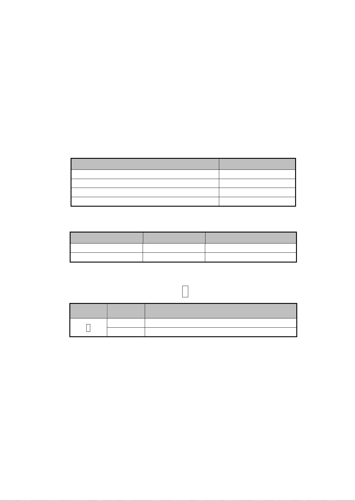
Item
Qty.
LP-ABR series Code Reader
1
Quick Reference (Englis h, Chinese and Japanese)
1 for each language
General information for safety (for EU users)
1
Sheet for "China RoHS Policy"
1
Unit Name
Model
Note
Control Cable
LP-ABR10-C5
5m
LAN Cable
LP-ABR10-L5
5m
Notation
Column
1
Regular type : Decodable distance 100 m m
2
Long range type : Decodable distance 200m m
Unpacking
Before unpacking the LP-ABR series Code Reader check that there has been no
damage to the packaging.
Check that the box includes t he items listed below. If any items are missing or
damaged, contact our local sales representative.
Included items
Optional items
Lineup
Model umber LP-ABR-1 1
1
Notation Description of Notation
8

Download Information
The user manuals, software, and device drivers are available from:
http://industrial.panasonic.com/ac/e/fasys/lasermarker/lasermarker/lp-abr10/index.jsp
1. LP-ABR10 series Setup/Operation Manual: Describe s t he features,
specifications, configur at i on and operation of the Fixed mount 2D Code
Reader LP-ABR.
2. Configurator LP-ABR: Is a software for the various settings and decoding
check on your computer.
3. Configurator LP-ABR Operation Manual: Describes t he operation of
Configurator LP-ABR so ftware.
9

Table of Contents
Safety notices ....................................................................................................... 3
Handle with care ................................................................................................... 4
General Terms and Conditi ons ............................................................................. 5
Applicable standards ............................................................................................ 7
Unpacking............................................................................................................. 8
Included items ...................................................................................................... 8
Optional items ....................................................................................................... 8
Lineup ................................................................................................................... 8
Download Information ........................................................................................... 9
1 Overview ....................................................................................................... 13
1.1 Supported Symbologies ................................................................................................... 14
1.2 Product Description ......................................................................................................... 14
2 How to use .................................................................................................... 20
2.1 Preparation ...................................................................................................................... 20
2.2 Reading Flow (Default) .................................................................................................... 22
2.3 Configuration.................................................................................................................... 22
2.4 Transfer Image Data ........................................................................................................ 22
3 Operation Mode ............................................................................................ 23
3.1 Single Reading Mode ...................................................................................................... 24
3.2 Reading Timeout Mode ................................................................................................... 26
3.3 External Trigger Mode ..................................................................................................... 30
3.4 Continuous Reading Mode .............................................................................................. 32
3.5 Test Mode ........................................................................................................................ 32
3.6 Cycle Buffer Function ...................................................................................................... 33
4 Configuration for Symbol Reading ................................................................ 35
10

4.1 Configuration parameters ................................................................................................ 35
4.2 Reading Parameter .......................................................................................................... 40
4.3 Camera Control Mode ..................................................................................................... 45
4.4 Detail of Table Mode ........................................................................................................ 46
5 Advance Features ........................................................................................ 48
5.1 Preset Mode ..................................................................................................................... 48
5.2 Output Additional Information .......................................................................................... 52
5.3 Save Image ...................................................................................................................... 59
5.4 PLC Link .......................................................................................................................... 62
5.5 Simultaneous reading of multiple labels .......................................................................... 62
5.6 Symbol Printing Check .................................................................................................... 63
5.7 Image Rotation................................................................................................................. 65
6 LAN (TCP/IP) connection ............................................................................. 66
6.1 Preparation ...................................................................................................................... 66
6.2 Configure IP address ....................................................................................................... 66
6.3 Default Settings................................................................................................................ 67
6.4 Check for LAN settings .................................................................................................... 69
6.5 Connect to LAN................................................................................................................ 70
6.6 Manage Commnunication Status..................................................................................... 70
6.7 Serial command for LAN settings .................................................................................... 72
6.8 Iinitialize LAN address ..................................................................................................... 75
7 Serial Command (RS-232C, LAN) ................................................................ 76
7.1 Communication ................................................................................................................ 77
7.2 Symbologies .................................................................................................................... 78
7.3 Symbol Reading (Operating mode, adjustment and diagnostic) ..................................... 80
7.4 Camera Control (1) (for Fixed Gain and Automatic Gain Control Mode) ........................ 83
7.5 Camera Control (2) (for Table Mode 1) ........................................................................... 84
7.6 Camera Control (3) (for table Mode 2) ............................................................................ 85
7.7 Image Preprocessing ....................................................................................................... 86
7.8 Preset Mode ..................................................................................................................... 86
7.9 PLC Link .......................................................................................................................... 87
7.10 Configuration Reference .................................................................................................. 88
7.11 Image Output and Image Storage ................................................................................... 88
11

7.12 LAN Settings .................................................................................................................... 89
7.13 Symbol Printing Check .................................................................................................... 90
7.14 General Operation ........................................................................................................... 91
7.15 Table of Character Code ................................................................................................. 91
8 Specifications ............................................................................................... 92
8.1 Specifications ................................................................................................................... 92
8.2 Reading Specifications .................................................................................................... 94
8.3 Dimensions ...................................................................................................................... 96
8.4 Interface ........................................................................................................................... 97
9 Troubleshooting .......................................................................................... 100
9.1 The reader does not start up or cannot communicate with a PC. ................................. 100
9.2 Symbol cannot be decoded ........................................................................................... 101
9.3 Fail to communicate through TCP/IP protocol ............................................................... 102
12

1 Overview
Reference
(1) This products is fixed mount (stationary type) Code Reader capable of two-dimensional
(2D) codes. These units incorporate the most innovative digital camera technologies,
related image recognition, and processing software. A pow erful high-speed processing
engine equipped with a dual-core CPU is adopted on the Fixed mount 2D Cod e Reader
LP-ABR. This manual may also refer to 2-dimensional barcodes as “sy m bols”.
(2) LP-ABR series provides the funct ion appropr iate to the dec oding o f direct marking pr inted
by laser marker.
-Image Preprocessing F unction:
Preprocesses the image to import and improves the image quality.
-Table Mode:
Maximum 8 types of decoding parameter can be set. This mode allow s you
to try the decodes one by one.
-Illuminaton Unit:
This unit has two types of illum ination: diffuse and direct. The light emission
pattern can be set depending on the object to decode.
-Symbol Printing Check:
Checks the symbol printing in in-line.
(3) Cycle Buffer Function(MAXIMG) allows the decode pr oces sing while high-speed
continuous imaging and saving the image to the memory.
(4) High resolution image sen s or (1.2 million pixels) is equipped.
(5) Protection degree: IP65
(6) The mounted LAN interface allows you to conne ct t he LAN port of the computer with
working Windows. (You may not establish a connec t ion with a co mput er de pendin g on it s
setting, spec and so on.)
Be sure to check the operation status when connecting a computer beforehand. This
connection status does no t warrant all operations of the computer.
13
1.1 Suppor t ed Symbologies
Regular Type
MAC Adderss Label
Long Range Type
2D Codes
Data Matrix (ECC200)
QR Code
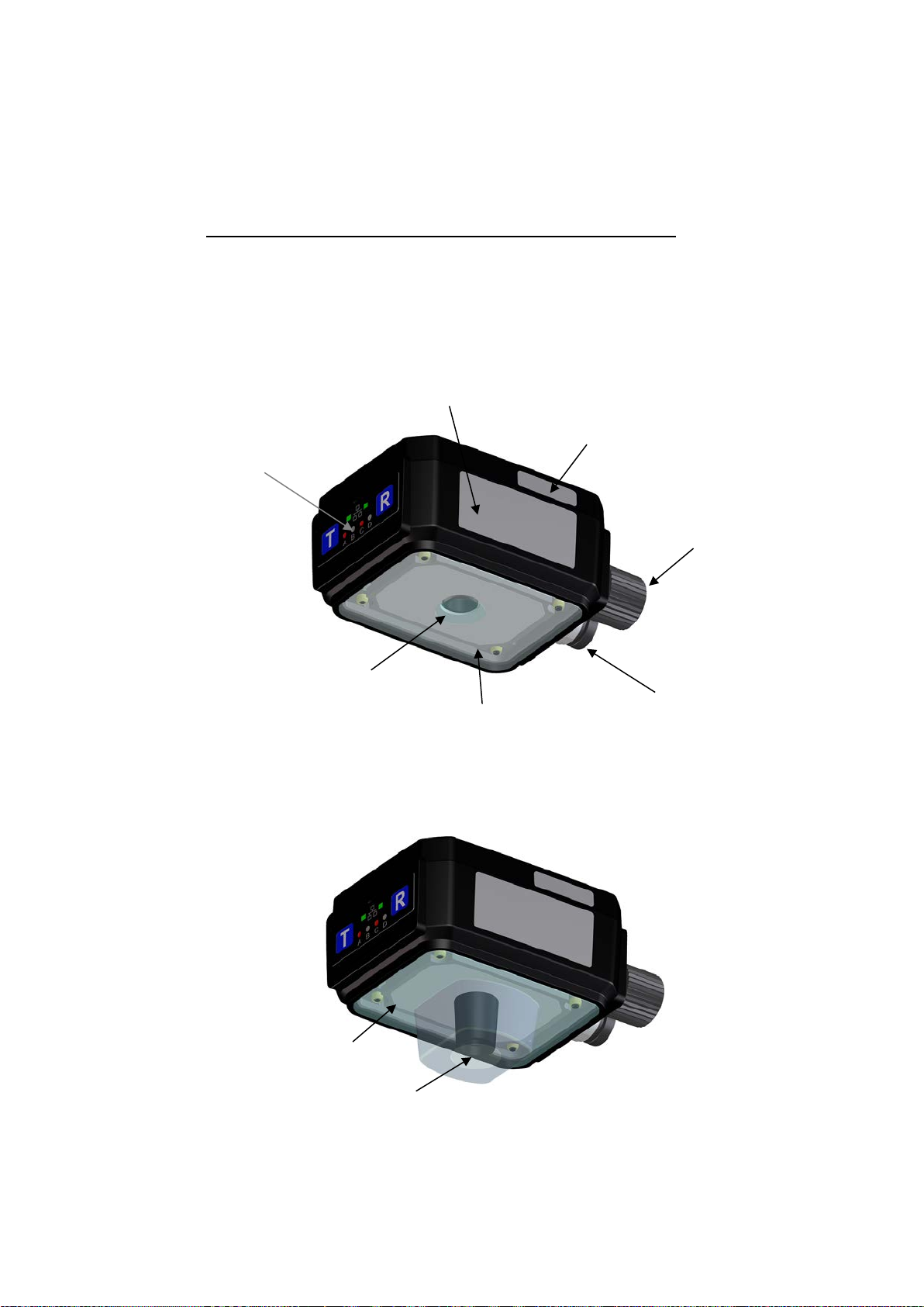
1.2 Produ ct Description
Operation Panel
Serial Number Label
Control Connector
Reading Window
Front Cover
Reading Window
Front Cover
LAN Connector
14
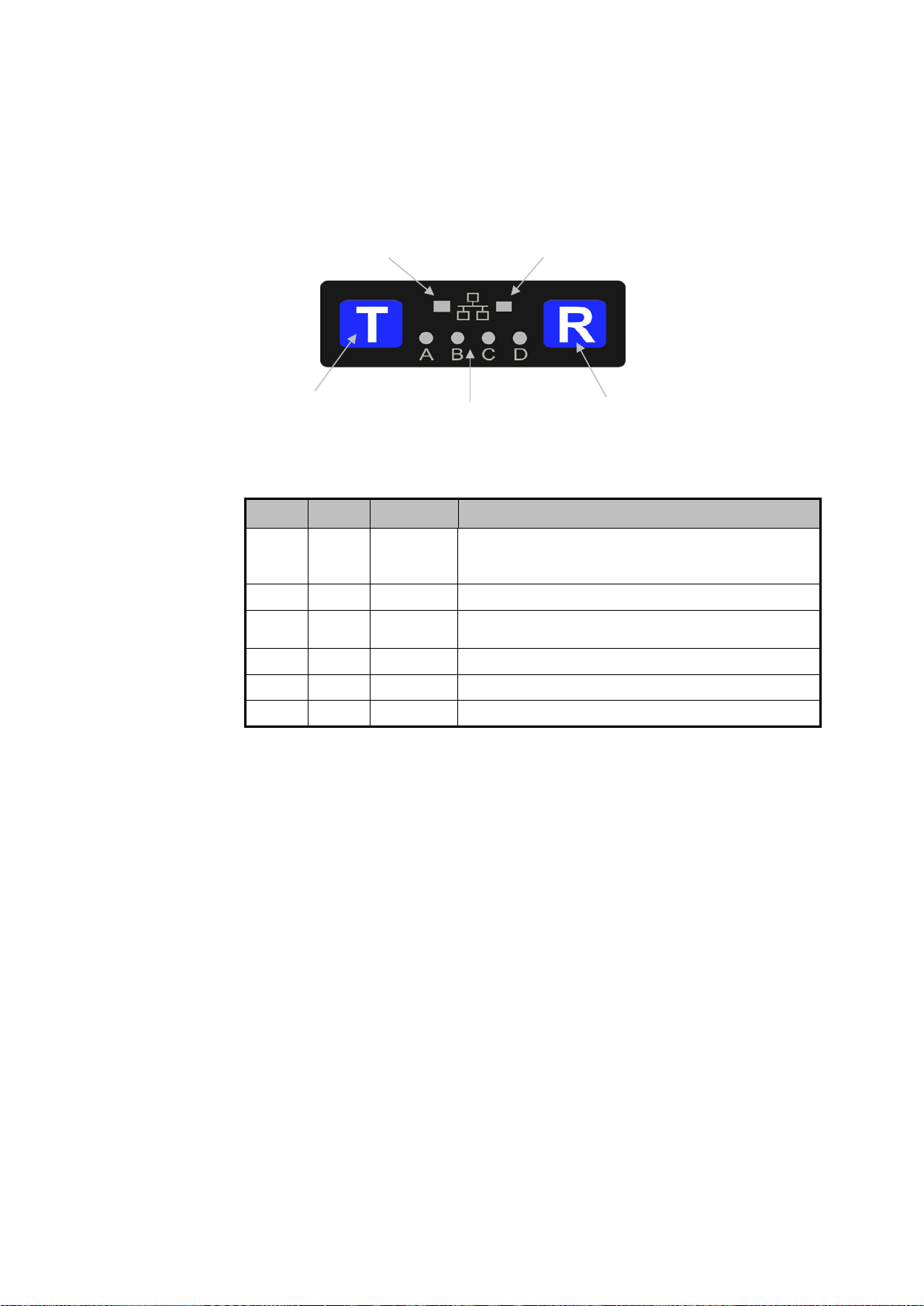
1.2.1 Operation Panel
" setting of
the PLC link is enabled
chractrers.
Link-LED
The operation panel consi sts of an action display monitor and 2 operation keys.
Teach Key
• Fucntion of Monitor LED
LED Color Name Description of Function
A Red Ready
B Green SYNC Turns on at a synchronizing input.
C Green GO
D Red NG Turns on whenthe reader fails to read.
Link Green LINK Turns on when the LAN is connected.
Act Orange ACTIVE Turns on at the data transmission/reception.
Act-LED
Monitor LED A to D
Turns on when Code Reader is operatable.
Blinking when the "SYNC IN by trigger area
Turns on when the reader suc cessfu lly reads symbo ls or
Read Key
For the monitor LED displ ay at automatic tuning,
refer to section “4.1 Configur at ion parameters”.
• Teach Key
Teach Key is used in auto-tuning function.
• Read Key
Read Key is used for a test/verification. When the Read Key is pressed, the
reader acts the same as when t he ext er nal synchronizing input sign al is
entered. Read Key is also us ed f or an automatic tuning in a combinat ion with
Teach Key.
15

1.2.2 Code Reader Connector (17 pins)
Signal
Default Setting
Description
GO signal is associated wit h G ood Read, which is
starting the next reading.
NG signal is associated wit h No Read, which is O N
starting the next reading.
Ready
signal
Ready signal is ON when the r eader i s r eady for
reading.
Busy #1 signal is ON during a reading (except
after decoding.
Reference
Code Reader Connect or i s used for connecting the power supply and digital
input/output with your Code Reader .
• Power Input
Power input of LP-ABR supplies DC24V.
• 4 Digital Outputs: LIGHT, OUT1, OUT2 and OUT3
The 4 Digital outputs are digital signal outputs with photo-coupler isol ation.
It outputs a control timing of the i ll umination control and the reader.
LIGHT output is a timing signal to activate t he ext er nal illumination
synchronizing with the camera’s image timing.
The outputs OUT1 to OUT3 are the signals for the external output of reading
action’s status or reading r esult’s status. Allocation of signals t o each output
and output time (setting time) can be configured by setting com mands.
Each of the following signal outputs can be configured to OUT1 to OUT3.
GO signal OUT1 output
NG signal OUT2 output
OUT3 output
Busy #1
signal
In the factory default settings the signals are as below:
OUT1 output GO signal,
OUT2 output NG signal,
OUT3 output Ready signal
When changing these parameters, save the settings to the internal flash
memory (using the WSETS command) and restart the reader.
ON during the specified time set by the GOOUT
command when the symb ol is d ecoded
successfully. And also thi s signal is OFF when
during the specified time set by the NGOUT
command when the symb ol is n ot decoded
successfully. And also thi s signal is OFF when
switch chattering delay), and this signal turns OFF
16
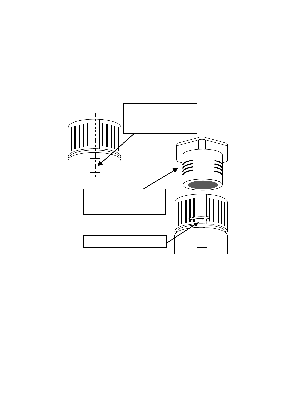
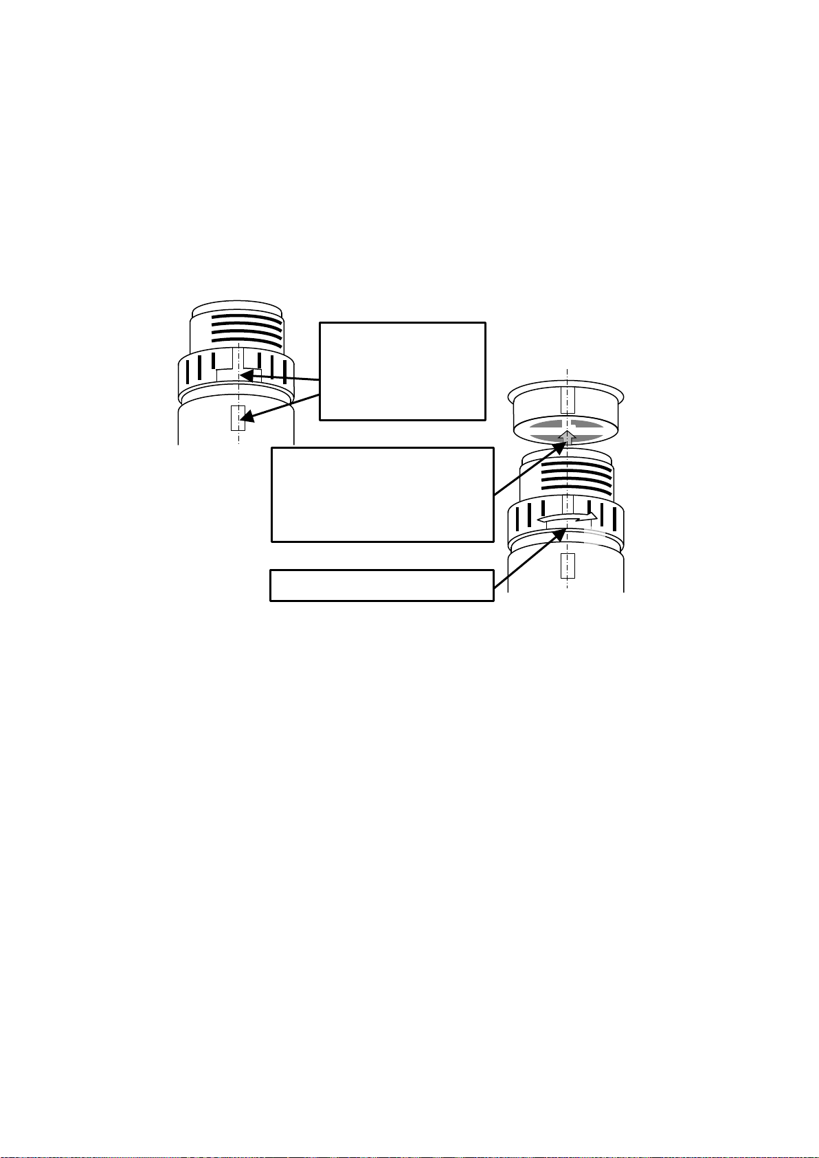
• Digital input (SYNC input):
Screw the connector to lock.
This signal is a photo coupler isol at ed i nput which is used for synchronous
inputs.
[Plug the connector]
① Adjust the positions of the
guide part of the cable nut
and the marking of the resin
part.
②
①
② After adjusting the positions of ①
and main unit’s connector guide,
insert the connector all the way in.
③
③
17
1.2.3 LAN Connector (8 pins)
Adjust the positions of
Adjust the of the positions of ①
Screw the connector to lock.
This connector is used for connecting the LAN cable (optional) of LP-ABR series
with your Code Reader.
[Plug the connector]
①
the guide part of the
cable nut and the
marking of the resin
part.
②
①
②
and the main unit’s connector
guide and insert the connector all
the way in.
③
③
18

1.2.4 Internal illumination unit
Block TOP
Block BOTTOM
Block
RIGHT
BLock
LEFT
Block CENTER
* The position of the illumination blocks switches in the image
for more detail.
Internal illumination unit il l um inates the central part of Code Re ader from inside
the front cover.
Illumination unit consis t s of a block: CENTER which is adjacent to reading
window and four blocks: TOP, BOTTOM, LEFT, and RIGHT. Each block's
illumination brightness and light on/off are controlab le.
The block CENTER is a bl ur r y diffused illumination with no direct iv it y. This
illumination is suitable for a r eadi ng of symbols with strong reflectiv it y (e.g.
symbols on mirror)
The four blocks around the CENTER are d ir ect i lluminations with directivity
and illuminate far in front of Code Reader.
Reading Window
rotating function. Refer to the section “5.7 Image Rotation”
You can configure the best illumination condition ea s ily by the configuration
tool Configurator LP-ABR. Adjust t he il lumination area and illumination ’s
intensity for a clear view.
An external illumination may be required when the view is still not clear.
Consult with our sales repr esent at ive for the configuration or selection of
illumination.
1.2.5 Reading Window
Is an entrance of light for imaging.
1.2.6 Front Cover
Is an acrylic cover to protect t he front sur f ac e.
1.2.7 MAC Address Seal
Indicates the MAC addres s of the LAN port.
19
2 How to use
Notice
Control
LP-ABR
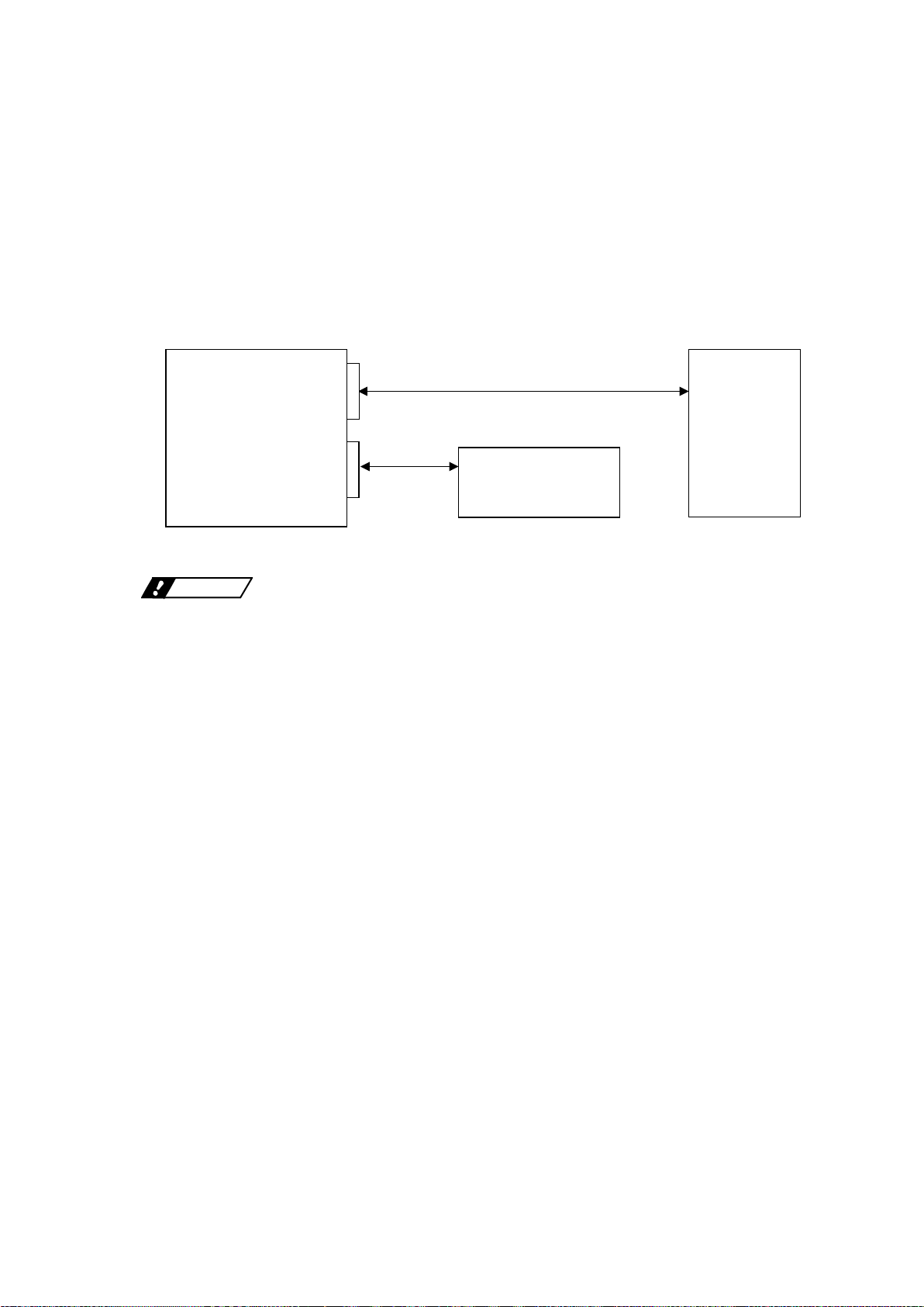
2.1 Preparation ① Establish a communicati on between the reader and the host device through
RS-232C interface/L AN interface. Connect a control device as needed.
<Example of Connection>
LAN Connector
LAN Cable
Host Device
Control Connector
Connecting devices whe n the power is supplied to the cable may c ause a
malfunction.
Cable
Control Device
(e.g. Power Supply)
PC, etc.
20

② Supply power from the int er fac e cable to the reader. The LED-A (Ready) turns
on (red) if the reader is correct ly powered. A combination of 2 long beeps and 3
short beeps will indicate that t he r eader has started up correctly.
③ Communication port selection (RS232C, LAN)
The communication port , w hich can be either RS232C and/or LA N as selected
by the “COMFROM” com ma nd, is used for the following purposes :
-Receiving serial commands such as reading trigger (SYNC input )
-Reading result transmission
† RS232C interface is selected as default.
Command Description
COMFROM=0 Only RS-232C (default)
COMFROM=1 Only LAN
COMFROM=2 RS-232C and LAN
21

2.2 Reading Flow (Default)
Command
Description
MODE=0
No image data sending (*)
MODE=1
MODE=2
MODE=3
Transfers image data every time (Continuous transfer)
MODE=4
Transfers image data when the reading is “NG” (Continuous transfer)
MODE=5
Transfers image data when the reading is “OK” (Contin uou s tr ansf er)
1. Good Read
- 1 short beep
- Symbol’s data will be sent t hrough the interface (RS232C, LAN).
- Digital output “GO” is ON.
- LED-C (GO) turns on (green).
Note: The activated period of “GO” and the monitor LED-C can be configured
through serial commands.
2. No Read
- No beep
- Error code will be sent through the interface (RS 232C, LAN).
- Digital output “NG” is ON.
- LED-D (NG) turns on (red).
2.3 Configuration
LP-ABR can be configured by sending the serial command through t he
communication port selected.
2.4 Transfer Image Data
Downloaded images by Code Reader can be transfered using “Configurator
LP-ABR” software from the commun ic at ion port to the host computer. By the
setting of Configurator L P-ABR, the images can be picked at the standby ti me or
can be transtered after the finish of reading. By the setting of Configurator
LP-ABR, the images can be picked at the standby time or can be transfered after
the end of reading. Images are converted into bmp files and ar e t r ansf er ed
through LAN interface. Th e transfer of a full-resolution ima ge t akes approx one
second.
Test Mode: DO NOT USE
*: Default setting
22

3 Operation Mode
Single Reading Mode
SYNCMODE=0
Single read for each SYNC input.
passes.
command) .
Normal Mode
symbols.
Mode, send a “stop” command.
LP-ABR has can be operated in following 2 modes.
Operational Mode Command Description
Reading Timeout Mode SYNCMODE=1 After SYNC input, the reader
External Trigger Mode SYNCMODE=2 The reader continues reading during
"Read” includes capturing and decoding an image.
The Diagnostic Mode is a vailable when the operation mode is in Sin gl e Reading
continues reading during the duration
time set by “TOTALLIM”. The reader
sends an error code when it fails in
reading when the duration time
the SYNC input is active. It receives
no g command (start reading
Mode.
Diagnostic Mode Command Description
Normal Mode TEST=0
Test Mode TEST=1
Continuous Reading Mode
continue
For normal use and to return to
For measurement of reading rate of
For camera adjustment. To release
the reader from Continuous Reading
Diagnostic Mode is used to configure the reader. Do not use the Diagnostic Mode
in normal operation.
23
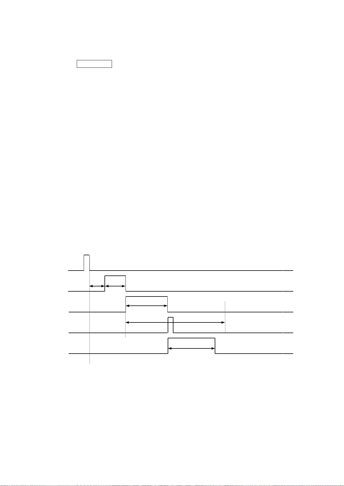
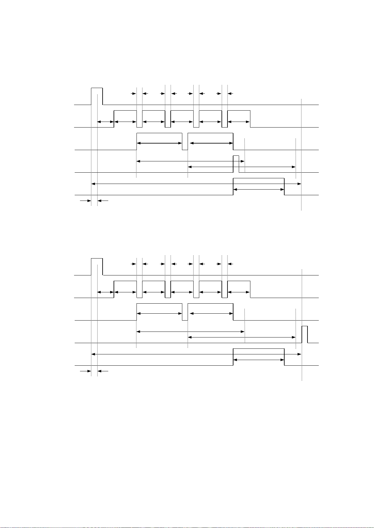
Timing Chart
DELAY
SYNC
IMAGE
DECODE
SERIAL
GOOUT
GOOUT
DECODELIM
decode1
image1
DELAY: The time from SYNC ON to reading.
CHATT: The time needed for eliminating the chattering.
IMAGE: The time duration for capturing an image.
DECODE: The time duration for decoding.
DECODELIM: The maximum time limit for decoding.
GOOUT: The length of time the GO signal is asserted.
NGOUT: The length of time the NG signal is asserted.
SERIAL: The time the data is output through the serial interface.
MAXIMG: The maximum number of images in the buffer.
WAITIMG: The interval time between capturing images.
Soft Trigger: The SYNC issued by serial command input.
Hard Trigger: The SYNC issued by digital input or Read Key.
3.1 Single Reading Mode
Code Reader performs a single read for each SYNC input.
3.1.1 Soft trigger, Good Read, Data transmission: After decode
24
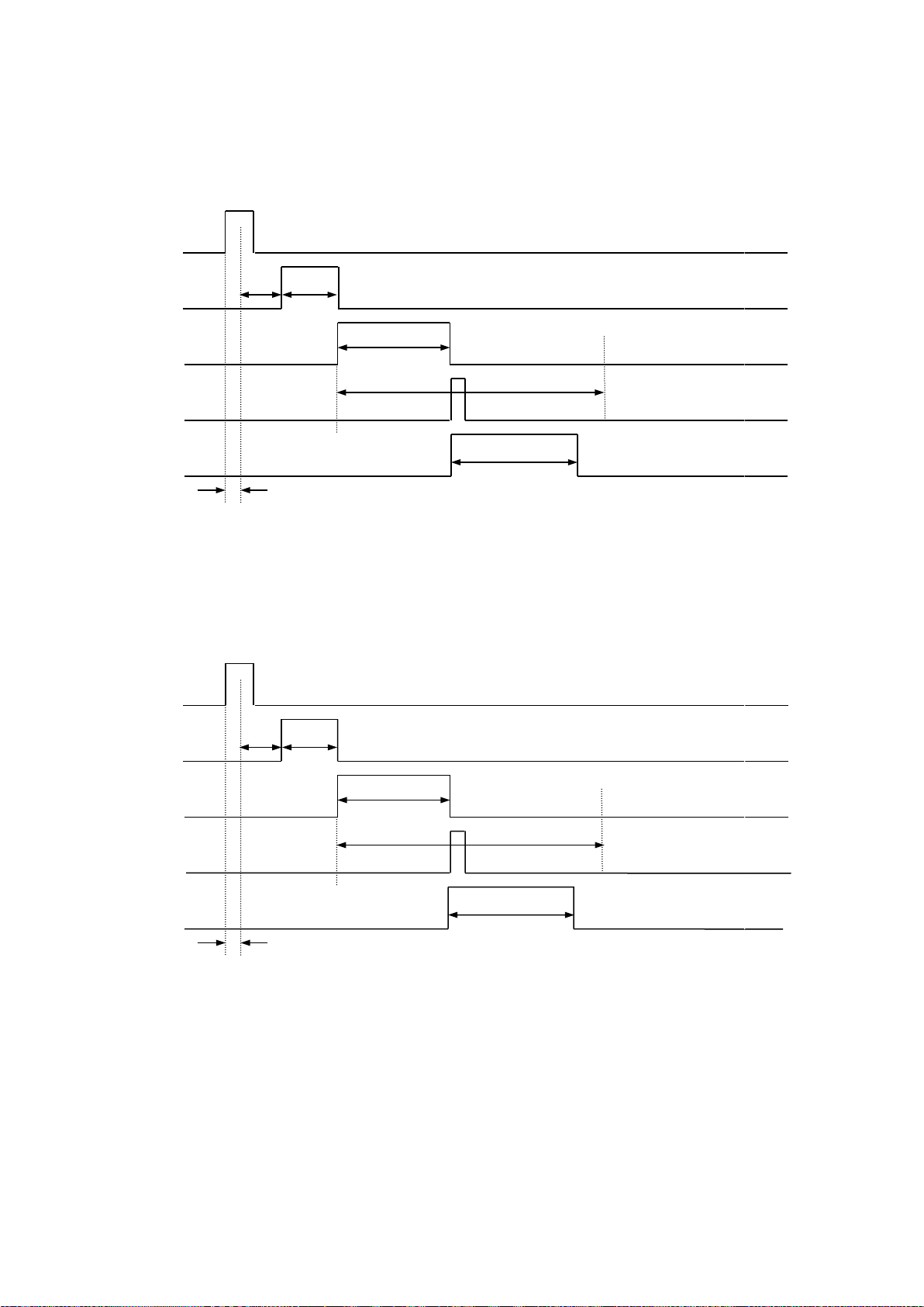
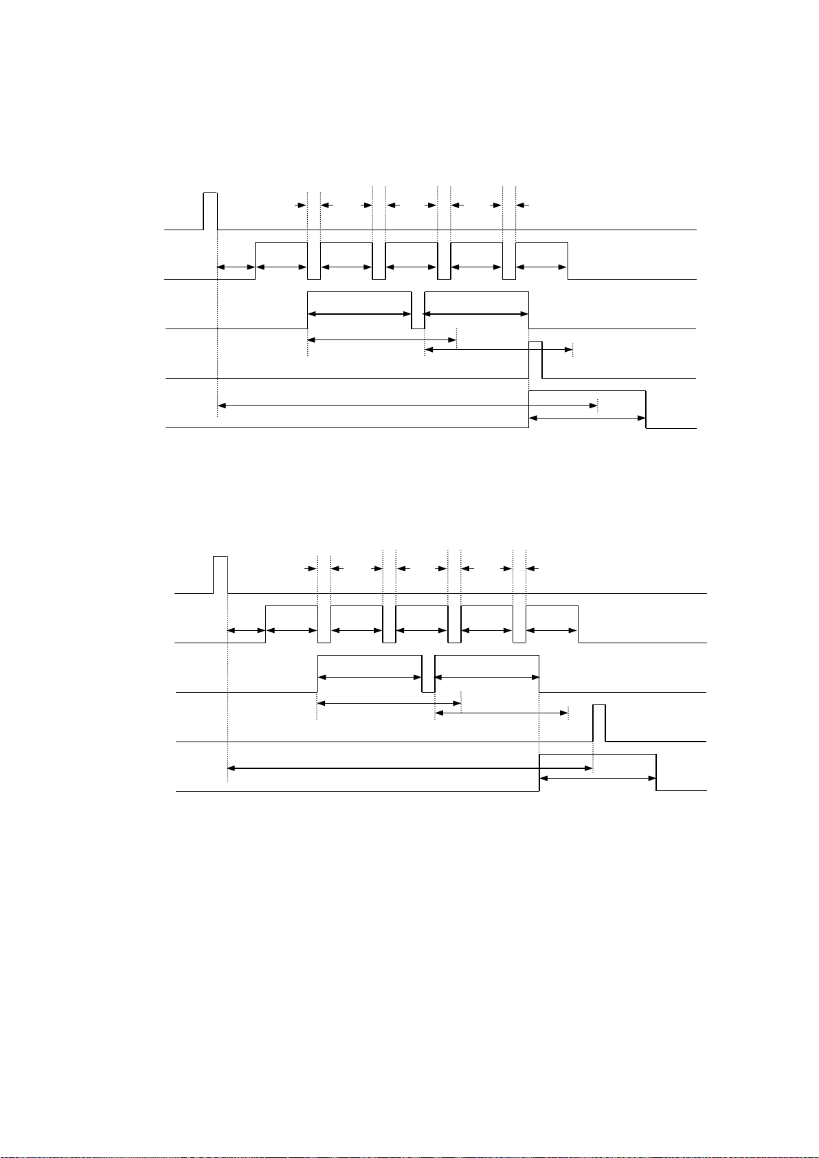
3.1.2 Hard trigger, Good Read, Data transmission: After decode
DELAY
SYNC
IMAGE
DECODE
SERIAL
GOOUT
GOOUT
CHATT
DECODELIM
decode1
image1
DELAY
SYNC
IMAGE
DECODE
SERIAL
NGOUT
NGOUT
CHATT
DECODELIM
decode1
image1
3.1.3 Hard trigger, No Read, Data transm iss ion: After decode
25

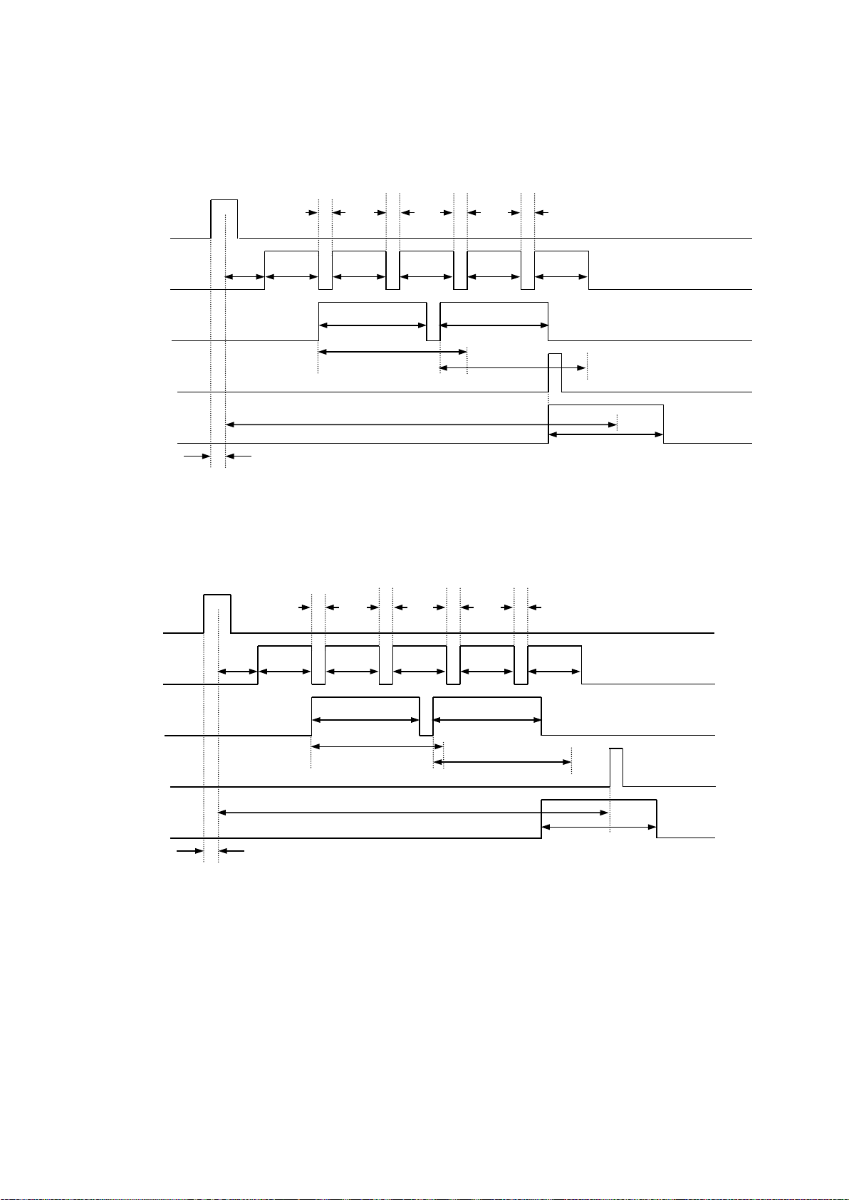
3.2 Reading Timeout Mode
DELAY
SYNC
IMAGE
DECODE
SERIAL
GOOUT
GOOUT
DECODELIM
DECODELIM
WAITIMG
WAITIMG
WAITIMG
WAITIMG
decode1
decode2
image1
image2
image3
image4
image5
TOTALLIM
DELAY
SYNC
IMAGE
DECODE
SERIAL
GOOUT
GOOUT
DECODELIM
DECODELIM
WAITIMG
WAITIMG
WAITIMG
WAITIMG
decode1
decode2
image1
image2
image3
image4
image5
TOTALLIM
Code Reader reads the symbol repeatedly during th e dur at ion time, set by “TOTALLIM” after
the SYNC input, or contin ues r eading until the decoding is successful. If the reader cannot
decode successfully in the duration t ime, it st ops rea ding and s ends an er ror c ode t o the host .
Typically MAXIMG is set to a number greater than one. The multi ple MAXIMG enables the
Cycle Buffer Function and the simultaneous parallel proces sin g between image import and
decoding. This may shorten the processing time.
The timing charts below ar e dr awn referring to the enabled cycle buffer function.
3.2.1 Soft trigger, Good Read, Data transmission: After decode
3.2.2 Soft trigger, Good Read, Data transmission: After SYNC OFF
26
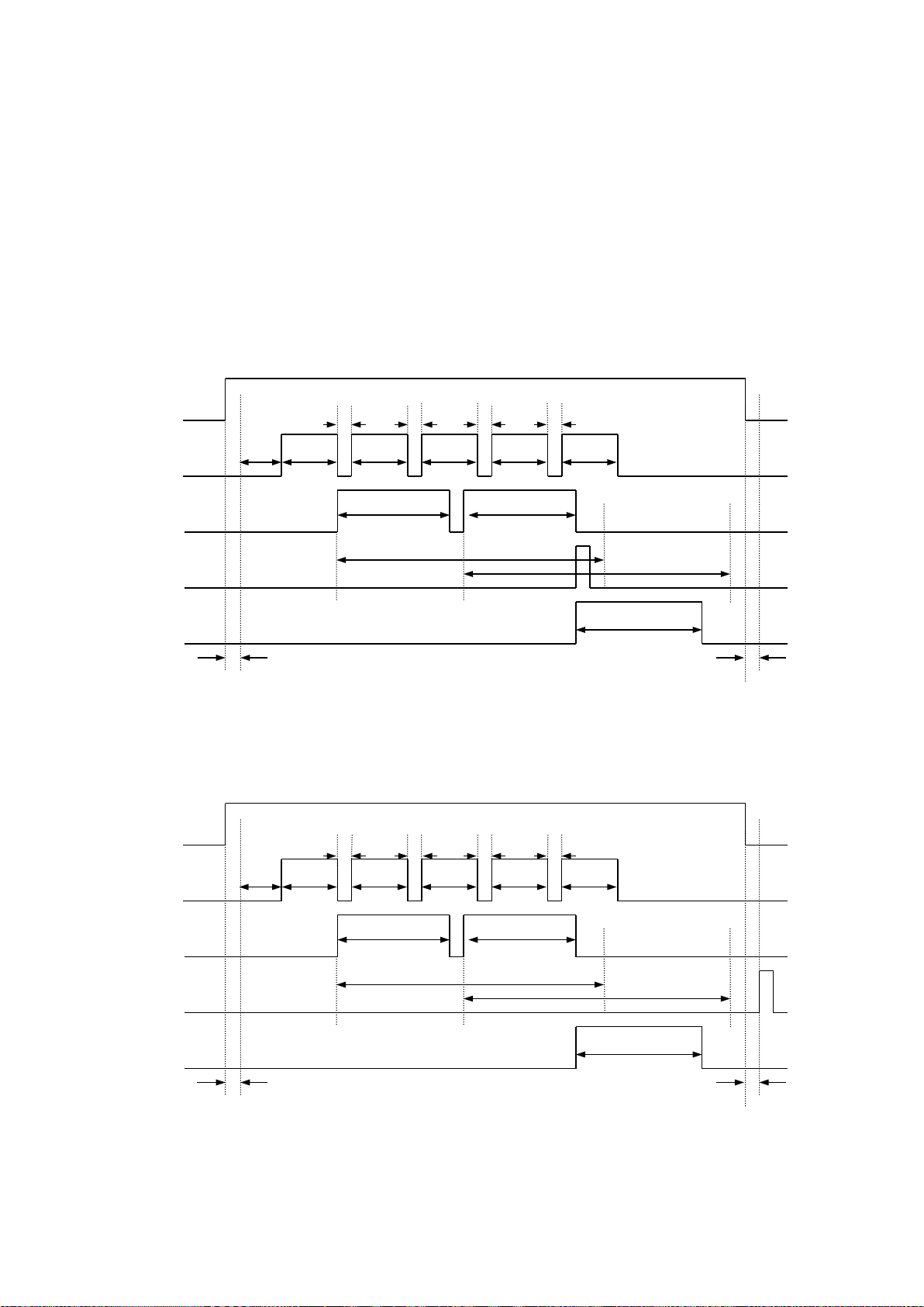
3.2.3 Hard trigger, Good Read, Data transmission: After decode
DELAY
SYNC
IMAGE
DECODE
SERIAL
GOOUT
GOOUT
CHATT
DECODELIM
DECODELIM
WAITIMG
WAITIMG
WAITIMG
WAITIMG
decode1
decode2
image1
image2
image3
image4
image5
TOTALLIM
DELAY
SYNC
IMAGE
DECODE
SERIAL
GOOUT
GOOUT
CHATT
DECODELIM
DECODELIM
WAITIMG
WAITIMG
WAITIMG
WAITIMG
decode1
decode2
image1
image2
image3
image4
image5
TOTALLIM
3.2.4 Hard trigger, Good Read, Data transmission: After SYNC OFF
27
3.2.5 Soft trigger, No Read, Data transmissi on: After decode
SYNC
DELAY
IMAGE
WAITIMG
WAITIMG
WAITIMG
WAITIMG
image1
image2
image3
image4
image5
DECODE
DECODELIM
DECODELIM
decode1
decode2
SERIAL
NGOUT
NGOUT
TOTALLIM
SYNC
WAITIMG
WAITIMG
WAITIMG
WAITIMG
DELAY
IMAGE
image1
image2
image3
image4
image5
DECODE
DECODELIM
DECODELIM
decode1
decode2
NGOUT
NGOUT
TOTALLIM
SERIAL
3.2.6 Soft trigger, No Read, Data transmissi on: After SYNC OFF
28
3.2.7 Hard trigger, No Read, Data transm iss ion: After decode
CHATT
DELAY
IMAGE
image1
image2
image3
image4
image5
SERIAL
SYNC
WAITIMG
WAITIMG
WAITIMG
WAITIMG
DECODE
DECODELIM
DECODELIM
decode1
decode2
NG-OUT
TOTALLIM
NGOUT
DELAY
SYNC
IMAGE
WAITIMG
WAITIMG
WAITIMG
WAITIMG
image1
image2
image3
image4
image5
SERIAL
NG-OUT
NGOUT
CHATT
TOTALLIM
DECODE
DECODELIM
DECODELIM
decode1
dcode2
3.2.8 Hard trigger, No Read, Data transm iss ion: SYNC OFF
29
3.3 External Trigger Mode
DELAY
SYNC
IMAGE
DECODE
SERIAL
GO-OUT
GOOUT
CHATT
DECODELIM
DECODELIM
WAITIMG
WAITIMG
WAITIMG
WAITIMG
decode1
decode2
image1
image2
image3
image4
image5
CHATT
DELAY
SYNC
IMAGE
DECODE
SERIAL
GO-OUT
GOOUT
CHATT
DECODELIM
DECODELIM
WAITIMG
WAITIMG
WAITIMG
WAITIMG
decode1
decode2
image1
image2
image3
image4
image5
CHATT
Code Reader reads the sy mbol repe ated ly dur ing the SYNC input is activ e. Ty pical ly
MAXIMG is set to a number gr eat er t han one. The multiple MAXIMG enab les the
Cycle Buffer Function and the simultaneous parallel proces sin g between image
import and decoding. This may s hor t en t he pr ocessing time.
The timing charts below ar e dr awn referring to the enabled cycle bu ff er function.
3.3.1 Hard trigger, Good Read, Data transmission: After decode
3.3.2 Hard trigger, Good Read, Data transmission: After SYNC OFF
30
 Loading...