

Panasonic LB-DH8 Owner's Manual
Operator Guide
DATA ARCHIVER
Model No. LB-DH8 series
Thank you for adopting Panasonic DATA ARCHIVER.
This document describes how the administrator manages the usage of the DATA
ARCHIVER.
Before using this unit, read “Cautions for regulations and safety/Overview/Disclaimers”
and observe the instructions in that document.
The DATA ARCHIVER LB-DH8 series includes the following modules and units.
Model Name Part Number
Base Module (Model Number: LB-DH80) SAS interface model LB-DH80A0G
iSCSI interface model LB-DH80S0G
FC interface model LB-DH80F0G
Bottom Module (Model Number: LB-DH81) LB-DH81Z0G
Extension Module (without the Writer Unit)
Extension Unit (Model Number: LB-XH82) and Control Unit (Model Number:
LB-XC82)
Extension Module (with the Writer Unit)
Extension Unit (Model Number: LB-XH82)
and Writer Unit (Model Number: LB-XD82)
SAS interface model LB-DH82A0G
iSCSI interface model LB-DH82S0G
FC interface model LB-DH82F0G
LB-DH82Z0G
SQW0319

Table of contents
Introduction
Overview of functions .............................................................................................................. 4
System configuration............................................................................................................................ 5
Host interface specifications ................................................................................................................ 7
Component names.................................................................................................................... 8
Handling a magazine and magazine drawer......................................................................... 17
Magazine............................................................................................................................................ 17
How the unit identifies a magazine .................................................................................................... 20
Magazine drawer................................................................................................................................ 21
Removing a magazine from a magazine drawer................................................................................ 23
Mounting a magazine on a magazine drawer .................................................................................... 25
Operations
Operation method ................................................................................................................... 27
Operating the control panel ................................................................................................... 28
Login onto the control panel............................................................................................................... 28
Basic operation .................................................................................................................................. 28
Inputting numeric and alphabetic characters ..................................................................................... 31
Basic screen configuration................................................................................................................. 33
Panel menu system............................................................................................................................ 35
Web interface operation ......................................................................................................... 70
Access to Web interface .................................................................................................................... 70
Web interface screen ......................................................................................................................... 71
Web interface menu system............................................................................................................... 72
Various Functions................................................................................................................. 101
Wake-on-LAN function/Turn off function via LAN port ..................................................................... 101
Encryption of write content............................................................................................................... 102
Verify Mode ...................................................................................................................................... 102
RAID functions ................................................................................................................................. 103
S.M.A.R.T. information..................................................................................................................... 105
Initializing and Saving/Restoring the configuration settings............................................................. 105
Email notification .............................................................................................................................. 106
2

Table of contents
SNMP............................................................................................................................................... 107
Software update............................................................................................................................... 108
Diagnostic ........................................................................................................................................ 109
Log functions.................................................................................................................................... 110
Magazine eject mode....................................................................................................................... 112
Others
Troubleshooting guide......................................................................................................... 114
Connection or installation problems................................................................................................. 114
Operating problems ......................................................................................................................... 117
Errors and warnings............................................................................................................. 127
List of error codes ............................................................................................................................ 130
List of warning codes ....................................................................................................................... 132
Appendix ............................................................................................................................... 137
Countermeasures against static electricity ...................................................................................... 137
Validated products ........................................................................................................................... 137
Contacting your support service provider ........................................................................................ 138
Initializing settings upon transfer or disposal ................................................................................... 138
Disclaimer ........................................................................................................................................ 138
Specifications ....................................................................................................................... 139
LB-DH8 series (common) ................................................................................................................ 139
Base Module.................................................................................................................................... 140
Bottom Module................................................................................................................................. 141
Extension Unit.................................................................................................................................. 142
Control Unit ...................................................................................................................................... 142
Writer Unit ........................................................................................................................................ 143
Extension Module (without the Writer Unit)...................................................................................... 143
Extension Module (with the Writer Unit)........................................................................................... 144
About copyright .................................................................................................................... 145
Glossary ................................................................................................................................ 146
Index ...................................................................................................................................... 147
3

Introduction
Overview of functions
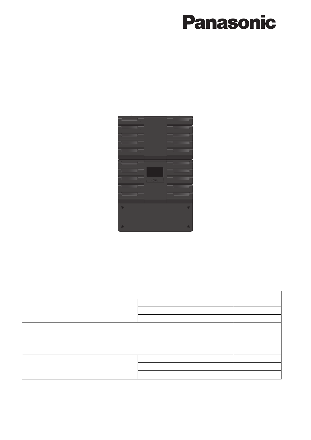
The Panasonic DATA ARCHIVER LB-DH8 series is a high-capacity storage library device using
optical discs.
The basic system of the library device in the LB-DH8 series consists of the LB-DH80 Base
Module and the LB-DH81 Bottom Module.
The Base Module has a set of built-in drive systems for reading and writing data and can store up to 76 magazines.
The Bottom Module has a function to insert or remove optical discs in the magazines into or from the drive system
and is combined with the Base Modules for use.
The DATA ARCHIVER LB-DH8 series can increase the number of magazines stored or have
multiple drive systems by adding the Extension Module LB-DH82.
There are several types of Extension Module: the LB-DH82Z0G without the drive system, the
three types of LB-DH82A0G / S0G / F0G with built-in drive system that have different interfaces.
The Extension Module LB-DH82Z0G is a combination of the Extension Unit LB-XH82 integrated with Control Unit
LB-XC82.
The Extension Module LB-DH82A0G / S0G / F0G is the Extension Unit LB-XH82 integrated with Writer Unit
LB-XD82A/ S / F respectively. These Writer Unit models have different interfaces.
The Extension Unit has the ability to store up to 76 magazines.
The Control Unit can be connected to the Base Module with the Extension Unit.
The Writer Unit has the Control Unit function and a single built-in drive system.
Maximum capacity of the unit
One magazine has a 1.2 TB capacity (for unformatted/RAID 0). The maximum capacity of one set in the basic
system consisting of the Base Module and the Bottom Module is 91.2 TB (for 76 magazines, unformatted/RAID 0).
The maximum capacity of the maximum system configuration, including the added six Extension Units is 638.4 TB
(for 532 magazines, unformatted/RAID 0).
Read/Write speed
The maximum read/write speed per ports is 216 MB/sec (RAID 0).
Interface
Serial Attached SCSI (SAS), iSCSI, or Fibre Channel (FC) is mounted as a host interface.
Compatibility with 19-inch rack
The unit can be installed in a 19-inch rack with a depth of 1,000 mm (40z) that conforms to the EIA standard.
4

Introduction Overview of functions
The unit
External power
supply
USB memory
NTP server DHCP server
SNMP manager
SMTP server
Server
Exclusive use connection cable
DC cable
I/O cable
SAS/iSCSI/FC
interface cable
iSCSI interface cable
LAN cable
Web interface
DHCP server
Only for iSCSI
interface model
Extension Module
(without the
Writer Unit)
Base Module
Extension Module
(with the Writer
Unit)
Extension Module
(with the Writer
Unit)
Bottom Module
System configuration example
System configuration
Connect various ports of the unit to a power source and various servers according to the functions to be used.
5

Introduction Overview of functions
∫ Required connections (solid/double lines)
Base Module/Bottom Module/Control Unit/Writer Unit:Uses a control interface port
External power supply: Uses the power connector and the I/O port (certain external power supply models that
have been validated to work with the unit only)
Server: Uses a host interface port
∫ Optional connections (dotted lines)
The LAN ports are used
Web interface (PC that uses a Web interface): When using a Web interface
NTP server: When using a timeserver
DHCP server: When using DHCP on a LAN port
SNMP manager: When using SNMP
SMTP server: When using the email notification
The iSCSI host interface port is used (iSCSI interface models only)
DHCP server: When using DHCP on the iSCSI host interface port
The USB ports are used
USB memory:
When using the following functions:
` Saving and restoring settings through the control panel
` Updating the software through the control panel
` Acquiring logs through the control panel
6

Introduction Overview of functions
Host interface specifications
The method of connecting a server to the Base Module or the Writer Unit depends on the type of host
interface.
SAS interface (LB-DH80A, LB-XD82A)
Use an external SAS cable to make a direct connection. In this case, note that the interface adaptor and cable shall
be compatible with a transfer rate of 6 Gbps.
SAS cable specification
≥
Use a Mini SAS 4x (SFF8088 26-CKT External Universal Key) cable for an external connection.
iSCSI interface (LB-DH80S, LB-XD82S)
Use a LAN cable to make an iSCSI connection. In this case, note that the interface adaptor and cable shall be
compatible with a transfer rate of 10 Gbps.
≥ LAN cable specifications
Use shielded LAN cable (straight connection) of Category 7 (CAT7).
FC interface (LB-DH80F, LB-XD82F)
Use an optical fiber cable to make a connection directly or via SAN. In this case, note that the interface adaptor and
cable shall be compatible with a transfer rate of 8 Gbps.
≥ Optical fiber cable specification
Use a multi-mode fiber optical cable that supports OM3 and has LC connectors.
7
Introduction
Component names
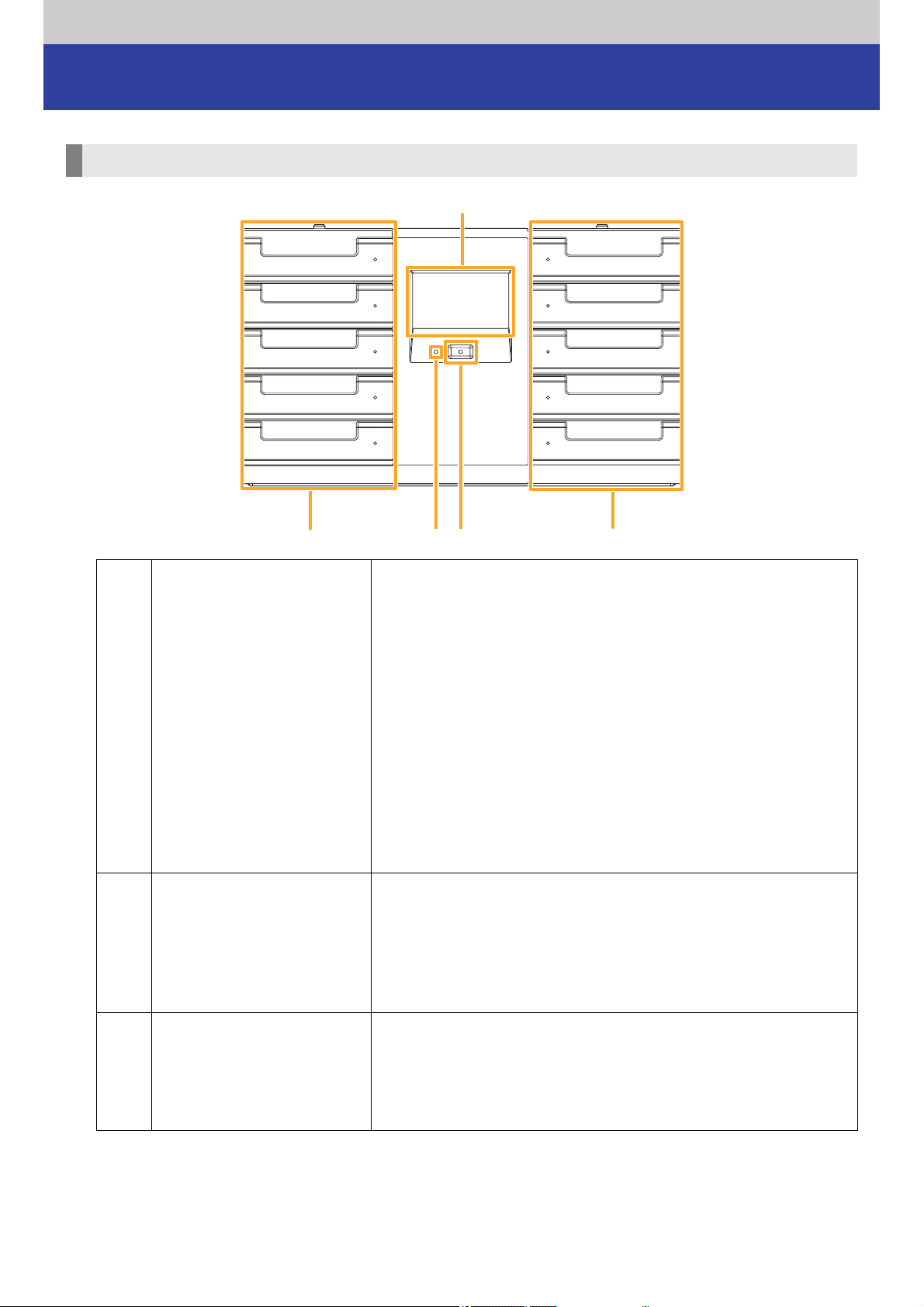
Base Module (LB-DH80)_Front panel
A Power button
B Information LED
Pressing the button causes the unit to be turned on and its LED
illuminates in green.
To turn off the unit, push the button and then select “YES” on the
selection menu of the control panel.
≥ The unit can be turned off through the control panel or Web
interface. Make the selection in the following order.
“Manage” “Shutdown” “Shutdown”
Turn off the unit after turning off the server connected to the unit or
terminating commands that are sent from the server to the unit.
Not doing so may cause trouble such as data loss or shutdown of
the server.
≥ The power button is not present on the rear panel.
≥ Even if the unit is turned off, a part of its circuitry remain on owing
to the Wake-on-LAN capability.
Informs you of errors or warnings.
≥ When the information LED illuminates in red, check the error or
warning message via the control panel.
If an error occurs, canceling the error state will turn off the
information LED. If a warning occurs, closing the popup window
on the control panel will turn off the information LED.
C Control panel
This panel serves as a 4.3 inch pressure-sensitive touch panel
display.
Use this touch panel to check the states and settings of the unit and
make various settings.
For more information, refer to “Operating the control panel” ( 28).
8

Introduction Component names
The unit has five magazine drawers on both sides capable of storing
up to 76 magazines.
D Magazine drawer
Operate the control panel with a finger. Do not press it with a sharp or hard object such as a mechanical pencil or
a screwdriver. Doing so may damage the touch panel display.
Note
≥ Missing or constantly-lit pixels may appear on the screen, but these are not malfunction.
≥ Normally, magazine drawers are locked. To open a magazine
drawer, unlock it from the control panel or Web interface.
For more information, refer to “Handling a magazine and magazine
drawer” ( 17).
9

Introduction Component names
Base Module_Rear panel
A Power connector
B Control interface port
Provides a +24 V DC power supply.
≥ Before disconnecting a power cable, confirm that LED 5
(POWER) listed in the following field H is off.
Serves as ports for a connection to the Bottom Module, Control
Unit, and the Writer Unit via the supplied exclusive use connection
cable.
C I/O port (RJ45)
D LAN port (RJ45)
E USB port
Serves as a port for serial communication with an certain external
power supply models that have been validated to work with the
unit.
≥ This is not a LAN port.
Serves as a port for the unit management (left: LAN1, right:
LAN2). When using a Web interface, a timeserver, an Email
notification or SNMP, note that network connection to this port is
essential.
The LED above the port represents the following.
` Left LED: LNK/ACT LED
LNK: illuminates in green
ACT: blinks in green
` Right LED: 1 Gbps/100 Mbps/10 Mbps LED
1 Gbps: illuminates in green.
100 Mbps: illuminates in orange.
10 Mbps: off
Serves as a port for connecting a FAT16 or FAT32 format USB
memory to update software or save setting values in or restore
them from the memory.
≥ The USB port is for
port for anything other than maintenance.
maintenance purposes only. Do not use this
F Nameplate Describes a product number, ratings, serial number, etc.
G Ventilation hole
Serves as a hole for air ventilation of the unit.
≥ Care should be taken not to block the hole.
10
Introduction Component names
Front
Indicates the operating state of the unit. (The LEDs are numbered
from left to right.)
` LED1 (CONTROLLER)/LED2 (CHANGER)/LED3 (DRIVE)
Running: illuminates in green
Stopped: off
H LED
I Fan ventilation hole
` LED 4 (INFORMATION)
LED illuminates in red in a situation that demands the
confirmation of the control panel. The LED turns off when no
confirmation is needed.
` LED 5 (POWER)
While energized: illuminates in green.
While de-energized: off
Serves as a hole for air ventilation of the unit during a fan
operation.
≥ The unit is equipped with a total of four fans: three regular fans
and one redundant fan.
≥ Care should be taken not to block the hole.
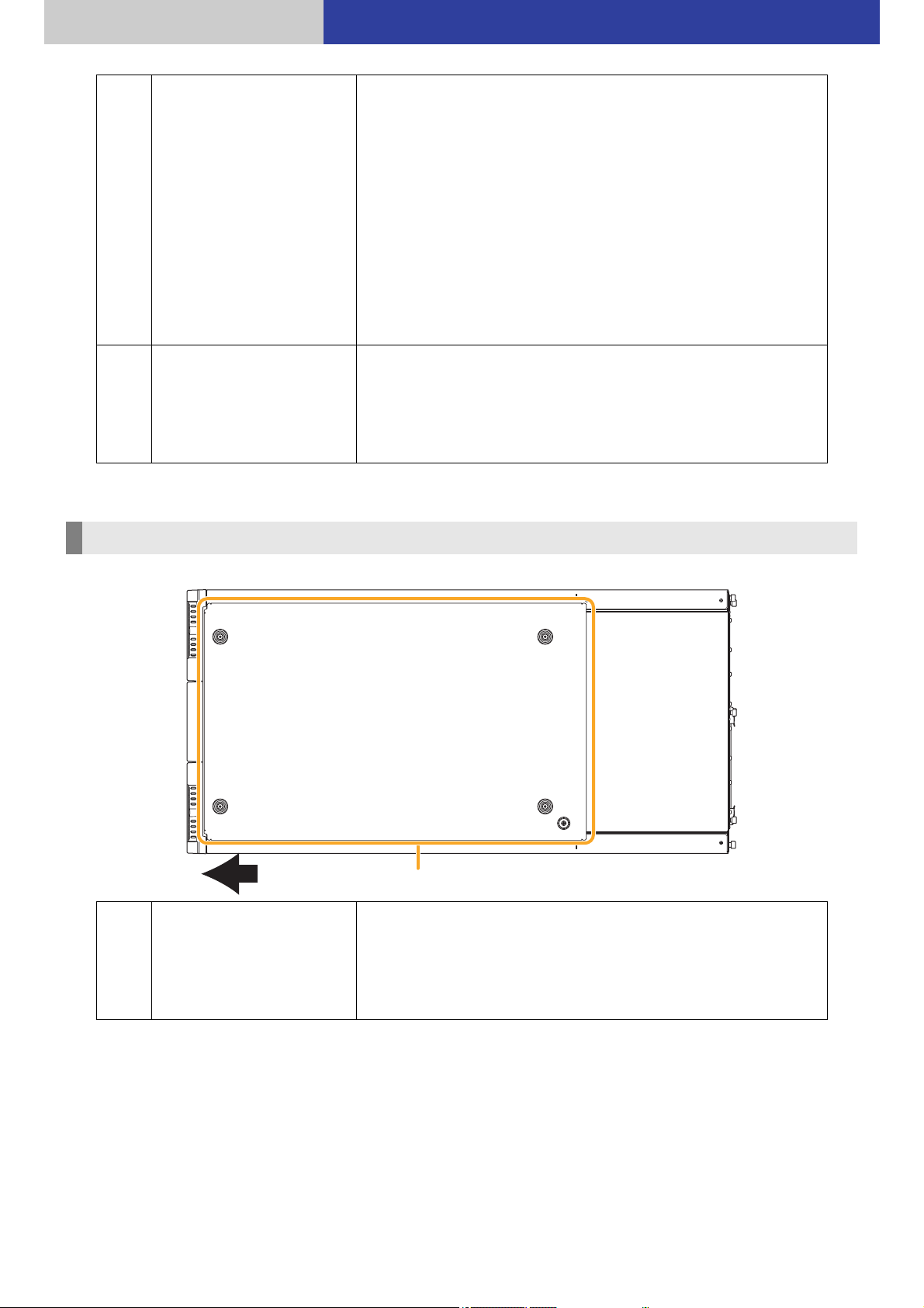
Base Module_Top panel
A Top panel
Serves as the top panel of the uppermost module of the system.
≥ The top panel is secured to the Base Module by four
thumbscrews and one M3 screw. To add the Extension Unit to
the top of the Base Module, remove the top panel from the Base
Module and then install it on the uppermost Extension unit.
11
Introduction Component names
a
b
c
Right-side view
Left-side view
Front
Front
Base Module_Side panel
A Ventilation hole
B Host interface port
Serves for air ventilation of the unit.
≥ Care should be taken not to block the hole.
Serves as a port for data transfer.
One of the following interface connector types is installed.
a: SAS interface port (connector: SFF8088 Mini-SAS)
b: iSCSI interface port (connector: RJ45)
c: FC interface port (connector: LC)
12
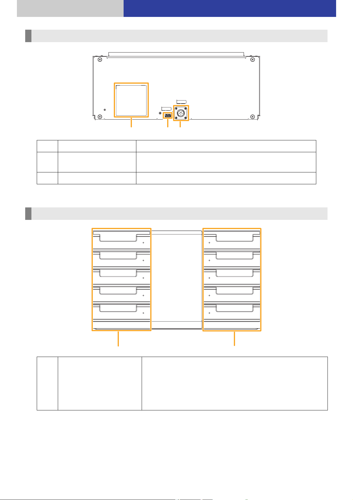
Introduction Component names
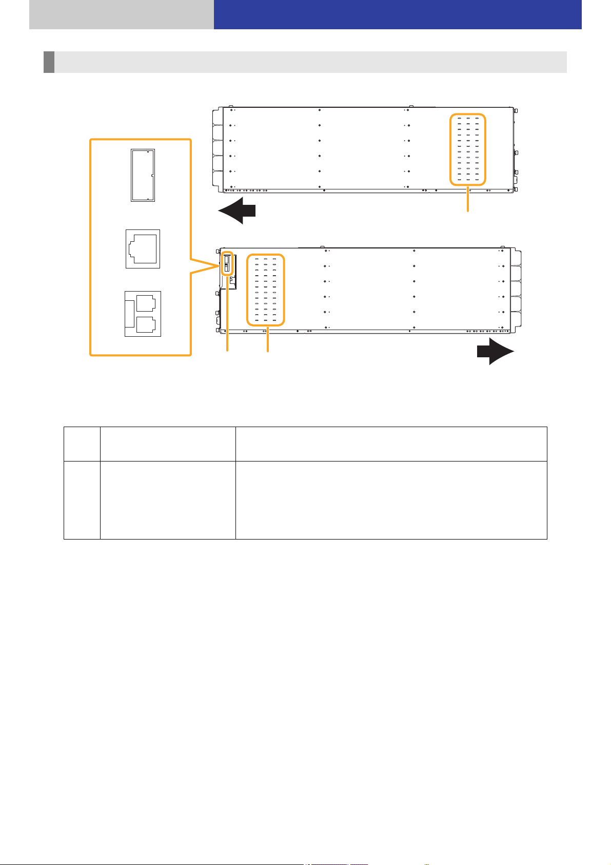
Bottom Module (LB-DH81)_Rear panel
A Power connector Provides a +24 V DC power supply.
B Control interface port
C Nameplate Describes a product number, ratings, serial number, etc.
Serves as ports for a connection to the Base Module via the
supplied exclusive use connection cable.
Extension Unit (LB-XH82)_Front panel
A Magazine drawer
The unit has five magazine drawers on both sides capable of storing
up to 76 magazines.
≥ Normally, magazine drawers are locked. To open a magazine
drawer, unlock it from the control panel or Web interface.
For more information, refer to “Handling a magazine and magazine
drawer” ( 17).
13

Introduction Component names
Control Unit (LB-XC82)_Rear panel
A Control interface port
B Nameplate Describes a product number, serial number, etc.
C Handle
Serves as ports for a connection to the Base Module via the supplied
exclusive use connection cable.
Use this part to remove the Control unit from the Extension Unit.
≥ Do not use this part for any purpose other than the above, such as
lifting this unit by holding this part.
Writer Unit (LB-XD82)_Rear panel
A Power connector
B Control interface port
Provides a +24 V DC power supply.
≥ Before disconnecting a power cable, confirm that LED 5
(POWER) listed in the following field E is off.
Serves as ports for a connection to the Base Module via the
supplied exclusive use connection cable.
14

Introduction Component names
C Nameplate Describes a product number, ratings, serial number, etc.
D Ventilation hole
E LED
F Handle
G Fan ventilation hole
Serves as a hole for air ventilation of the unit.
≥ Care should be taken not to block the hole.
Indicates the operating state of the unit. (The LEDs are numbered
from left to right.)
` LED1 (CONTROLLER)/LED3 (DRIVE)
Running: illuminates in green
Stopped: off
` LED2 (CHANGER)/LED 4 (INFORMATION)
Always Off
` LED 5 (POWER)
While energized: illuminates in green.
While de-energized: off
Use this part to remove the Writer Unit from the Extension Unit.
≥ Do not use this part for any purpose other than the above, such
as lifting this unit by holding this part.
Serves as a hole for air ventilation of the unit during a fan
operation.
≥ The unit is equipped with a total of four fans: three regular fans
and one redundant fan.
≥ Care should be taken not to block the hole.
15

Introduction Component names
a
b
c
Right-side view
Left-side view
Front
Front
Extension Unit equipped with a Control Unit/Writer Unit_Side panel
A Nameplate Describes a product number, serial number, etc.
B Ventilation hole
Host interface port
C
(Only when the Writer Unit
is equipped)
Serves as a hole for air ventilation of the unit.
≥ Care should be taken not to block the hole.
Serves as a port for data transfer.
One of the following interface connector types is installed.
a: SAS interface port (connector: SFF8088 Mini-SAS)
b: iSCSI interface port (connector: RJ45)
c: FC interface port (connector: LC)
16

Introduction
Write-enabled
Write-disabled
Handling a magazine and magazine drawer
Magazine
Use a dedicated magazine for the unit.
For more information about the magazines that
≥
≥ Each magazine has a capacity of 1.2 TB (unformatted/RAID 0) and a data storage life of 50 years (at 30 oC (86 oF)
in a 70 % environment)*.
* The numbers are estimates based on an acceleration test.
can be used, please contact your vendor.
A User label area
B Write disable switch
Area for sticking a user label.
Align and stick the label in a recessed area.
Switch for preventing data from being erased or overwritten by
mistake. Before loading a magazine into the unit, confirm that this
write disable switch at the front of the cartridge has been set at a
desired position.
To enable writing: Slide the switch to the left (with no lock mark)
To disable writing: Slide the switch to the right (with a lock mark)
≥ Writing to a magazine can be disabled through an application. For
more information about the settings, refer to the user guide for the
application.
Handling and storing a magazine
≥ For details on environmental constraints, refer to the “Cautions for regulations and safety” attached to the
magazine.
≥ Do not expose the magazine to water.
≥ Do not drop the magazine.
≥ Do not leave the magazine exposed to high temperatures and high humidity, corrosive gas, or direct sunlight.
≥ Do not disassemble the magazine.
≥ Store or use the magazine in an environment without dew condensation.
≥ Do not place heavy objects on a magazine.
≥ Do not stack magazines on each other.
RFID tag
Near the user label area of the magazine, RFID tag is embedded to identify and manage magazines.
Do not stick a metal object or an RFID on the parts around the user label area. Writing to and reading from an
embedded RFID tag may fail as a result, causing malfunction.
17

Introduction Handling a magazine and magazine drawer
e.g.,
70 mm (2.75z) or smaller
7 mm (0.28z) or more, 14 mm (0.55z) or smaller
DATA ARCHIVER
e.g.,
14 mm (0.55z) or smaller
14 mm (0.55z) or smaller
User label
The following labels can be attached to a user label area of a magazine.
` 1D or 2D code label (only one of them)
` Label with a character string (for magazine management)
The 1D/2D code label and the character string label can be used separately or together. However, the label should
be attached in the predetermined area and not overlap each other.
Specifications on 1D codes>
<
Standard: Code39
Label size: 14 mm (0.55z) (H) k 70 mm (2.75z) (W) or smaller (with margins)
Maximum number of characters: 12 characters (without stop and start codes)
Thin bar width: 12 mil (= 0.305 mm (0.012z)) or more
Ratio of thin bars to thick bars: 1:2.75
Inter-character gap: 12 mil (= 0.305 mm (0.012z)) or more
Bar length: 7 mm (0.28z) or more
Leading and trailing margins: 3.05 mm (0.12z) or more
Color (recommended) Black (code), White (background)
Specifications on 2D codes>
<
Standard: QR code (Model 2)
Label size: 14 mm (0.55z) k 14 mm (0.55z) or smaller (with margins)
Maximum number of characters: 256 characters (alpha-numeral), 256 byte (UTF-8)
Cell size: 4 dots* or more and 0.254 mm (0.01z) or more per side
Margins in four directions: 4 cells or more (A larger size is easier to read)
Color (recommended) Black (code), White (background)
* “dot” refers to the smallest printing unit of a printing device.
e.g., Printing with the maximum size of 14 mm (0.55z) k14 mm (0.55z)
600 dpi printer: Printable with Version 7 or earlier (45 k 45 cells)
300 dpi printer: Printable with Version 4 or earlier (33 k33 cells)
18

Introduction Handling a magazine and magazine drawer
Note
≥ No system operation is affected by the absence of a user label.
≥ A user label shall be attached with no wrinkles and air bubbles.
≥ A glossy user label surface may be difficult to read.
≥ A user label shall neither protrude out of a predetermined area nor attached in other than the predetermined
area.
≥ A user label partially protruded out of the predetermined area or partially soiled shall be replaced.
≥ Additional user labels shall not be attached to an existing user label at label replacement.
≥ The 1D/2D code label shall be attached beside the write disable switch in the user label area.
≥ The operation cannot be guaranteed if the content of the 2D code label is character other than alphanumeric
and UTF-8.
≥ If UTF-8 contains a code that cannot be converted to Shift JIS, the contents will not displayed on the control
panel.
≥ When using the Web interface, the read contents are send as UTF-8 code to the Web browser.
For more information about UTF-8 code which can be viewed on the Web browser, refer to the operating
instructions of your Web browser.
Advice on the disposal of magazines
Formatting magazines or deleting its content using the function of a server or application will only change file
management information, and will not erase data in DATA ARCHIVER Magazines completely. The content of
RFID tags will not be erased, either. When DATA ARCHIVER Magazines are disposed of, it is recommended that
they be physically destroyed.
19

Introduction Handling a magazine and magazine drawer
How the unit identifies a magazine
The unit uses an RFID tag for magazine identification and management.
The unit can scans and uses a 1D/2D code label for magazine identification and management.
When an RFID tag is damaged and the magazine cannot be identified by the unit, the 1D/2D code label can be used
for magazine identification by the unit.
When there is trouble identifying an RFID tag, the unit cannot identify the magazine without the 1D/2D code label.
20
Introduction Handling a magazine and magazine drawer
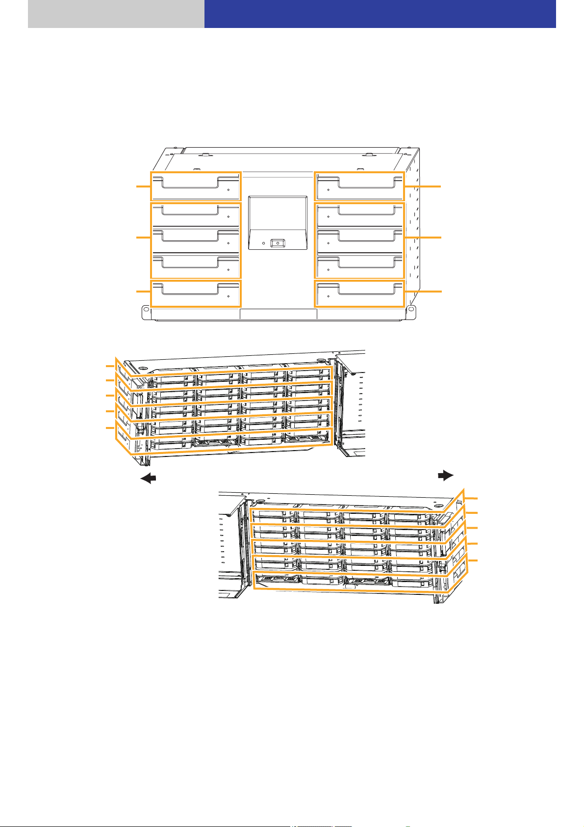
L1
L2
L3
L4
L5
R1
R2
R3
R4
R5
Left top drawer
Left middle drawers
Left bottom drawer
Right top drawer
Right middle drawers
Right bottom drawer
L5
L4
L3
L2
L1
R5
R4
R3
R2
R1
Left cross-section view
Front
Front
Right cross-section view
Magazine drawer
The Base Module (LB-DH80) and the Extension unit (LB-XH82) each can be equipped with five magazine drawers
(10 drawers in total) on both sides.
≥ The order of the middle three drawers is exchangeable on each side.
≥ The numbers L1 – L5 and R1 – R5 are assigned to the magazine drawers.
21

Introduction Handling a magazine and magazine drawer
1
2
3
4
5
6
7
8
Bottom magazine drawers
Magazines cannot be attached.
Each magazine drawer can store up to eight magazines (six magazines only in the bottom drawer).
≥ A magazine number, consisting of the magazine drawer number and any of a number between 1 and 8, is
assigned to each magazine. For example, the magazine on the upper right of the L1 magazine drawer is L1-4.
≥ The bottom magazine drawers, 6 and 8, on both sides cannot have magazines attached.
22
Introduction Handling a magazine and magazine drawer
Handle
Vertically placed
Horizontally placed
Convex part
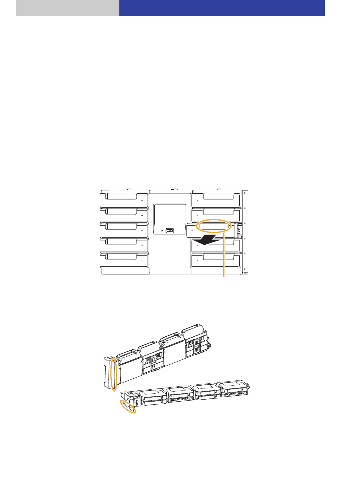
Removing a magazine from a magazine drawer
1 Unlock the magazine drawer.
≥ The unit locks a magazine drawer to prevent it from being opened by mistake.
To remove a magazine, unlock the magazine drawer through the control panel or Web interface as follows.
` Control panel: “Manage”
` Web interface: “Manage”
≥ When unlocking the magazine drawer has been disabled by an application, refer to the application manual,
give permission to unlock the magazine drawer, and try to unlock the magazine drawer.
≥ When unlocked, the magazine moves forward slightly.
When unlocking the magazine drawer has been performed incorrectly and the magazine drawer must be
locked, draw out the magazine drawer 5 cm (2q) or more and then push it in again to ensure that the
magazine is locked. After that, inventory is executed to acquire the magazine information and the changer
unit operates.
≥ The magazine drawer cannot be unlocked manually.
2 Draw the magazine drawer.
≥ Hold the handle of the magazine drawer with one hand and pull it toward you, and while supporting the
bottom of the magazine drawer with the other hand, pull it completely out.
“Open Drawer” ( 67)
“Open Drawer” ( 97)
≥ The lower front part of the bottom magazine drawer on each side has a convex shape, so place the drawer
vertically, not horizontally.
23
Introduction Handling a magazine and magazine drawer
White lever
≥ Before drawing out the magazine drawer, make sure to unlock it. Drawing out the magazine drawer by force
may cause damage to it.
≥ Do not draw out the magazine drawer too hard.
≥ Do not put your hand in the unit from the opening of the magazine drawer.
≥ Do not step on, hang from, or lean against the magazine drawer, or perform any other actions that result in
applying too much force on it.
≥ Do not leave the magazine drawer pulled out.
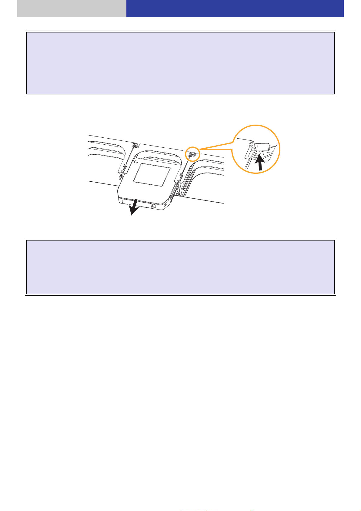
3 Remove a magazine from the magazine drawer.
≥ Remove the magazine while pushing the white lever on the right rear of each magazine toward the arrow.
≥ Do not touch any mechanical portion other than portions indicated in the instructions of the procedure. Failure
to observe this instruction may cause the content of the magazine to fall out.
≥ Be sure to push the white lever when removing the magazine.
≥ Do not remove the magazine by main force. Failure to observe this instruction may damage the magazine and
magazine drawer.
≥ Do not place the magazine drawer and the magazine on an unstable surface.
24

Introduction Handling a magazine and magazine drawer
Guide rails on the chassis side
Part with the bend on the side of the
magazine drawer
Mounting a magazine on a magazine drawer
Preparation
≥ Attach a user label onto a magazine. ( 17)
≥ Confirm that the write disable switch of the magazine is in position. ( 17)
1 Mount a magazine on a magazine drawer.
≥ Insert the magazine in the direction of the arrow with the “ ” side facing upward.
≥ After inserting a magazine into a magazine drawer, confirm that it cannot be pulled out.
≥ If the bottom magazine drawer on the both side is placed horizontally, it may be damaged.
Mount the magazine drawer into the Base Module or the Extension Unit.
2
≥ Insert the part with the bend on the side of the magazine drawer into the guide rails on the side of the chassis
of the Base Module or Extension Unit, and push it all the way inside until it locks. The unit does not work
unless the magazine drawer is pushed to the end.
≥ Make sure that the direction of the magazine drawer is inserted correctly.
≥ After the magazine drawer has been pushed in, inventory is executed to acquire the magazine information
and the changer unit operates.
25

Introduction Handling a magazine and magazine drawer
≥ Do not carry a magazine drawer with its mounting surface down. Failure to observe this instruction may cause
the magazine to drop.
≥ Do not touch any mechanical portion other than portions indicated in the instructions of the procedure. Failure
to observe this instruction may cause the content of the magazine to fall out.
≥ Do not remove the magazine by main force. Failure to observe this instruction may damage the magazine and
magazine drawer.
≥ Do not put your hand in the unit from the opening of the magazine drawer.
≥ Do not place anything other than magazines and magazine drawers in the unit.
≥ Be careful not to catch your fingers in the magazine drawer.
≥ Do not slam the magazine drawer shut.
Note
≥ Use a dedicated magazine.
≥ A magazine drawer with eight magazines weighs approximately 3 kg (6.7 lbs) at maximum (with six magazines
weighs approximately 2.4 kg (5.3 lbs) at maximum).
≥ Mount a magazine on a magazine drawer securely. Failure to follow this instruction may cause injury, magazine
damage, or the unit failure due to falling.
≥ Do not load a damaged magazine into a magazine drawer.
≥ Do not load a magazine into a magazine drawer in an incorrect direction to prevent damage. First check an
arrow direction. ( 25)
26

Operations
Operation method
Set the following items as required.
Operations for setting and maintaining the unit
The following two methods can be used to set and maintain the unit.
` Operating the control panel on the front of the unit ( 28)
Operate the control panel to check the states of the unit, make various network settings, make various settings
for opening and closing the magazine drawer, and operate the magazine drawer.
` Operating the Web interface ( 70)
Access the unit with the Web browser to check the state of the unit, make various network settings, make various
settings for opening and closing the magazine drawer, and operate the magazine drawer.
Note
When settings of the unit have been changed, it is recommended that the settings be saved through the control
panel or Web interface. ( 55, 89)
Operations by a application
The unit operates according to SCSI commands via the host interface, and it operates according to the following
commands.
` Drive system control: MMC command
` Changer unit control: SMC command
The unit can be operated by an application running on a server connected to the unit.
The DATA ARCHIVER Manager and storage control application are used to control the changer unit and read it from
the magazine or write data onto a magazine.
For information on how to use, refer to the application manual.
27
Operations
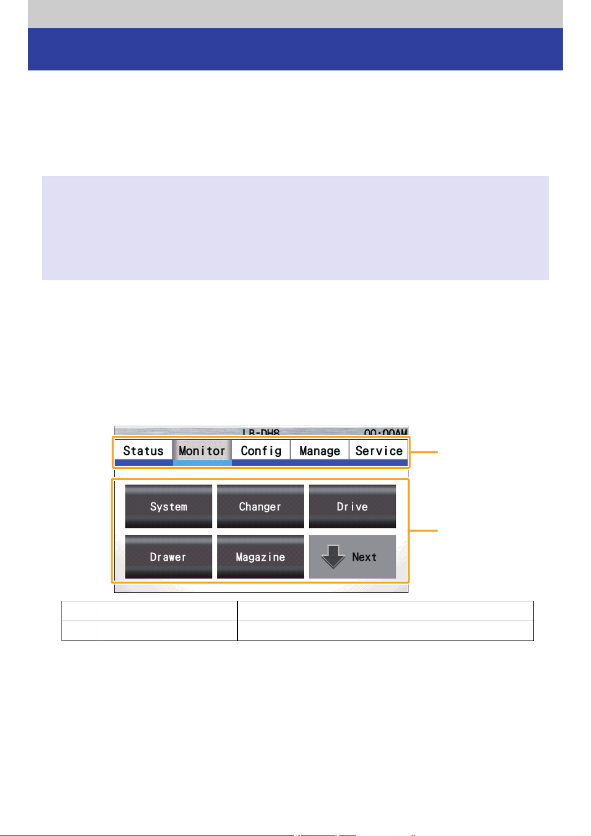
Menu screen
Operating the control panel
Login onto the control panel
≥ When using the “Monitor”, “Config”, and “Manage” menus on the control panel, input a password for login.
≥ When using the unit for the first time after installation, log in onto the control panel and change a password.
≥ Logout is performed automatically 1 hour after login is performed.
≥ For logout, select “Manage” “Enable Password Lock” in order.
Note
≥ The control panel will log out automatically after 1 hour.
≥ The “Status” menu can be confirmed without login.
≥ The “Service” menu cannot be used. The menu is for maintenance.
≥ Logging into the Web interface is not possible while the user is logged into the control panel.
Logging into the control panel while the user is logged into the Web interface will cause a logout from the Web
interface.
Basic operation
Touch the control panel and select an item for operation.
Do not touch two or more items at the same time.
Touching the item causes a beep to allow for screen switching, setting, or processing in response to the selected
item.
A Menu tab Select the desired tab to change the setup items (B).
B Setup item Select a menu item to proceed to its setup screen. ( 35)
28

Operations Operating the control panel
Setup screen
Menu screen
C Menu button Touch here to return to the displayed menu.
D Return button Touch here to return to the previous screen.
Touch “ ” or “ ” to scroll the screen.
E Scroll button
F Input button Touching an item indicated with “ ” will display the input screen.
≥ The number of “ ” between an “ ” and “ ” indicates the
number of pages and “ ” indicates a current page position.
G
Button for proceeding to next
menu
Indicates the next setup item.
29
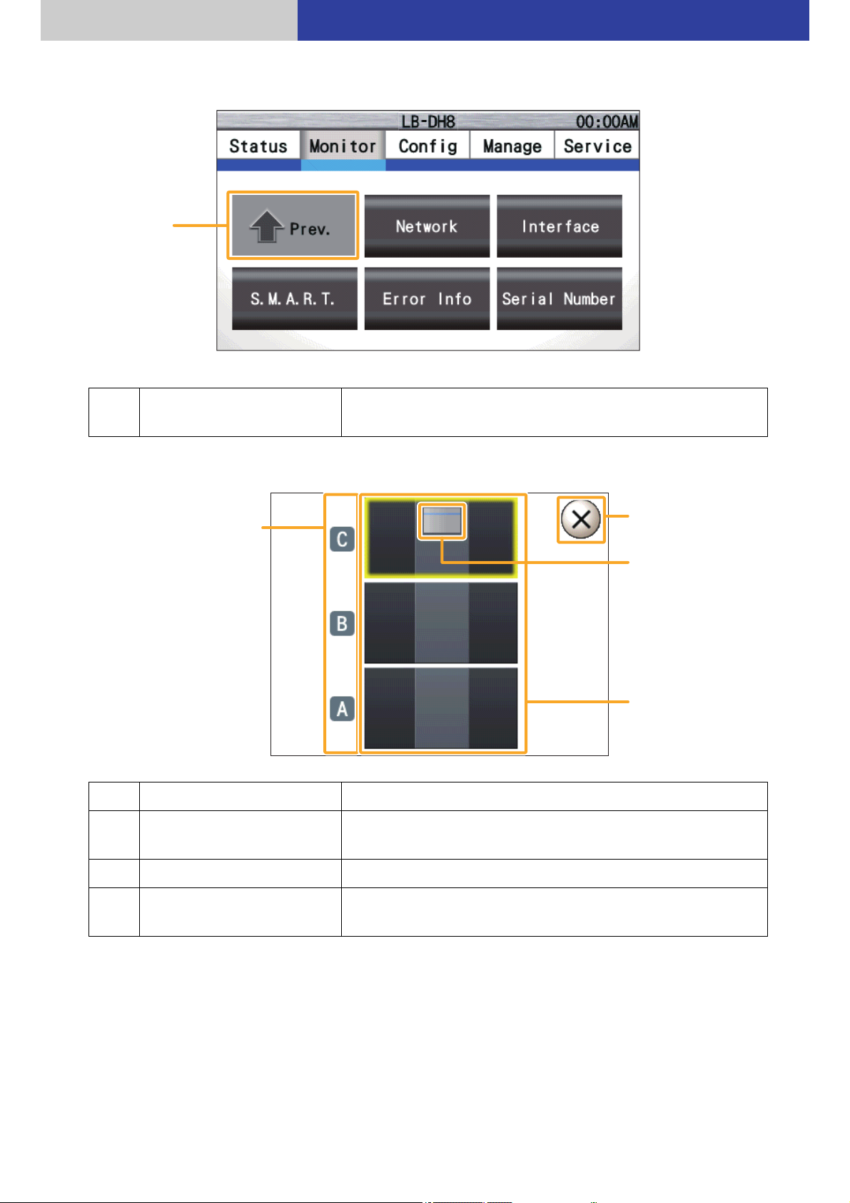
Operations Operating the control panel
Menu screen
Module selection screen
H
Button for returning to
previous menu
Indicates the previous setup item.
I Module name Indicates the module names.
J Cancel button
K Base Module Indicates the position of the Base Module.
L Module selection button
Touch here to close the pop-up window and return to the
previous menu.
Selecting a module displays the next screen.
≥ A module shown in grey cannot be selected.
30
 Loading...