

Panasonic KX-TC1709LBB Service Manual
ORDER NO. KM40109678C3
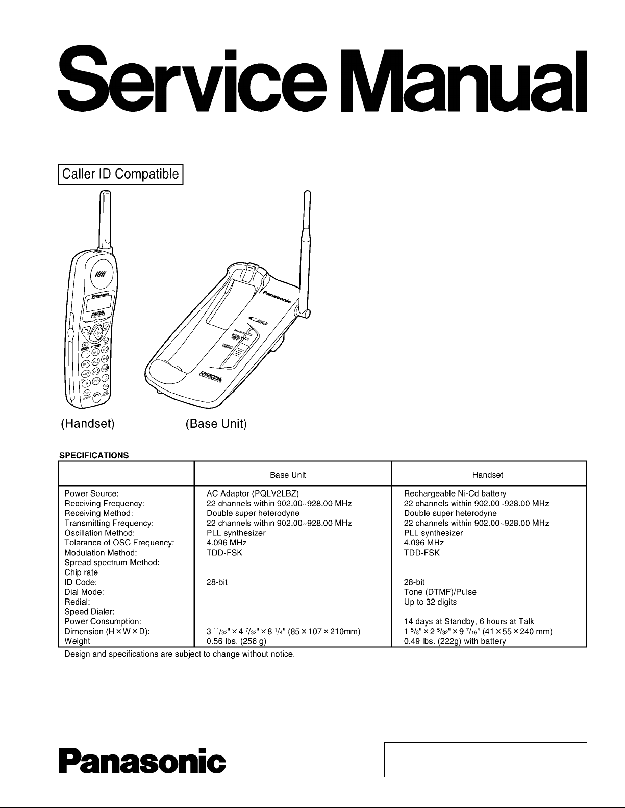
Telephone Equi pment
KX-TC1709LBB
900MHz Digital Cordless Phone
Black Version
(for Brazil)
© 2001 Kyushu Matsushita Electric Co., Ltd. All
rights reserved. Unauthorized copying and
distribution is a violation of law.
KX-TC1709LBB
CONTENTS
Page Page
1 STANDARD BATTERY LIFE 4
2 LOCATION OF CONTROLS
2.1. Base unit
2.2. Handset
3 DISPLAY
4 CONNECTIONS
4.1. Adding Another Phone
5 OPERATION
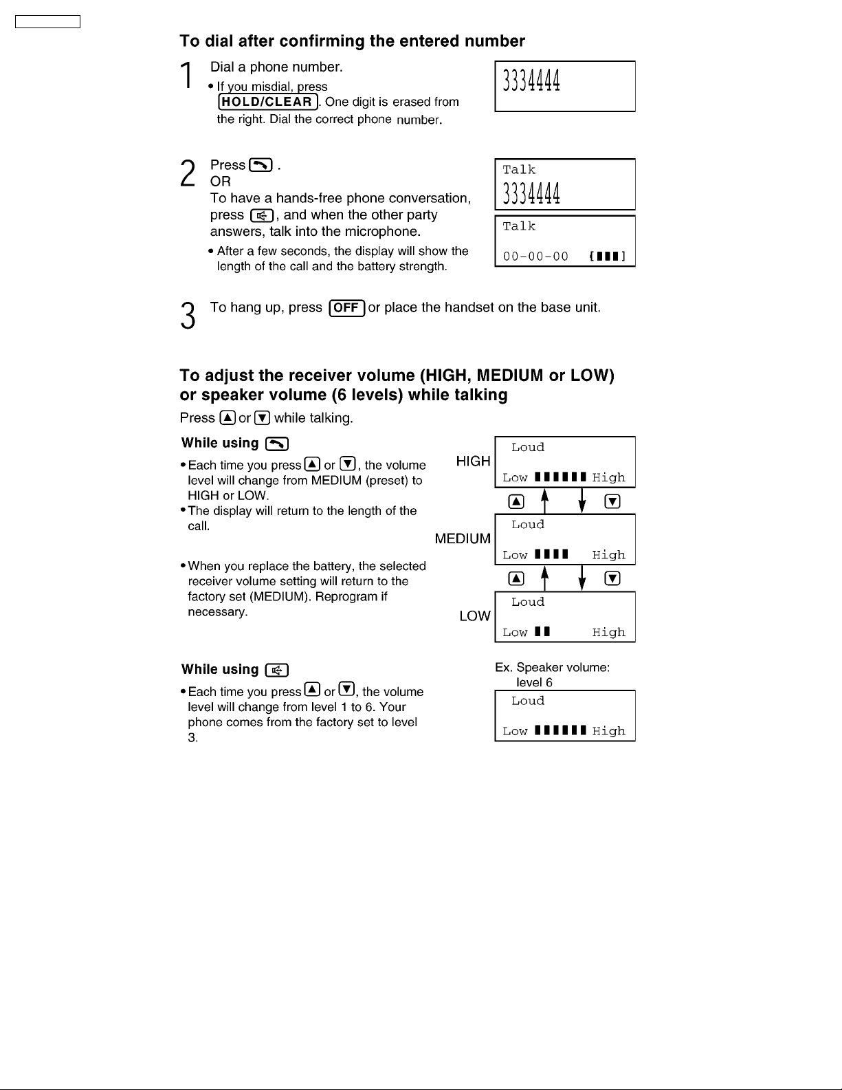
5.1. Making Calls
5.2. Answering Calls
5.3. FLASH Button
6 DISASSEMBLY INSTRUCTIONS
7 ASSEMBLY INSTRUCTIONS
7.1. Assembly the LCD to P.C. Board (Handset)
8 TROUBLESHOOTING GUIDE
8.1. Check Power
8.2. Check Battery Charge
8.3. Check Link
8.4. Check the RF Unit
8.5. Check Handset Transmission
8.6. Check Handset Reception
8.7. Check Call ID
9 TEST MODE
9.1. Test mode flow chart for Base Unit
9.2. Test mode flow chart for Handset
9.3. X101 Check
9.4. Base Unit Reference Drawing
9.5. Handset Reference Drawing
9.6. FREQUENCY TABLE
10 DESCRIPTI ON
10.1. Frequency
10.2. Time Division Duplex (TDD) operation
10.3. Signal Flowchart in the Whole System
11 EXPLANATION OF BBIC (Base Band IC) DATA
6
6
7
8
10
11
12
12
16
17
18
20
20
21
22
23
23
24
29
29
29
30
30
31
32
32
33
34
35
35
35
36
COMMUNICATION
11.1. Calling
11.2. To Terminate Communication
11.3. Ringing
11.4. Ports for Transmitting and Receiving of Data
12 BLOCK DIAGRAM (Base Unit)
13 CIRCUIT OPERATION (Base Unit)
13.1. DSP (Digital Speech/Signal Processing: IC501)
13.2. EEPROM (IC551)
13.3. Power Supply Circuit
13.4. Reset Circuit
13.5. Telephone Line Interface
13.6. Parallel Connection Detect Circuit
13.7. Signal Route
13.8. Calling Line Identification Circuit (Caller ID)
14 BLOCK DIAGRAM (Handset)
15 CIRCUIT OPERATION (Handset)
15.1. Construction
15.2. Power Supply Circuit
15.3. Charge Circuit
15.4. Ringer and Handset SP-Phone
15.5. Sending Signal
15.6. Reception Signal
16 CPU DATA (Base Unit)
16.1. IC501
17 CPU DATA (Handset)
17.1. IC201
18 EXPLANATION OF IC TERMINALS (RF Unit)
18.1. IC101
19 HOW TO REPLACE FLAT PACKAGE IC
19.1. Preparation
19.2. Procedure
2
37
37
37
37
37
38
39
39
39
40
41
42
43
44
45
47
48
48
48
49
49
49
50
51
51
52
52
53
53
54
54
54

19.3. Modification Procedure of Bridge 54
20 CABINET AND ELECTRICAL PARTS (Base Unit)
21 CABINET AND ELECTRICAL PARTS (Handset)
22 ACCESSORIES AN D PACKING MATERIALS
23 TERMINAL GUIDE OF ICエS, TRANSISTORS AND DIODES
23.1. Base Unit
23.2. Handset
24 REPLACEMENT PARTS LIST
24.1. Base Unit
24.2. Handset
25 FOR SCHEMATIC DIAGRAM
25.1. Base Unit (27 SCHEMATIC DIAGRAM (Base Unit))
25.2. Handset (28 SCHEMATIC DIAGRAM (Handset))
55
56
57
58
58
58
59
59
60
63
63
25.3. Memo
26 SCHEMATIC DIAGRAM (RF Unit)
27 SCHEMATIC DIAGRAM (Base Unit)
28 SCHEMATIC DIAGRAM (Handset)
29 CIRCUIT BOARD (RF Unit)
30 CIRCUIT BOARD (Base Unit)
30.1. Component View
30.2. Flow Solder Side View
31 CIRCUIT BOARD (Handset)
31.1. Component View
31.2. Flow Solder Side View
KX-TC1709LBB
63
64
65
66
68
70
71
71
72
73
73
74
3
KX-TC1709LBB
1 STANDARD BATTERY LIFE
4
KX-TC1709LBB
5
KX-TC1709LBB
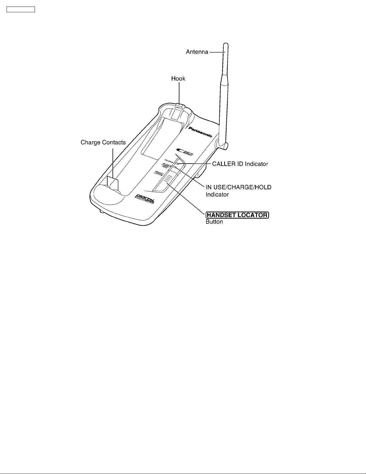
2 LOCATION OF CONTROLS
2.1. Base unit
6
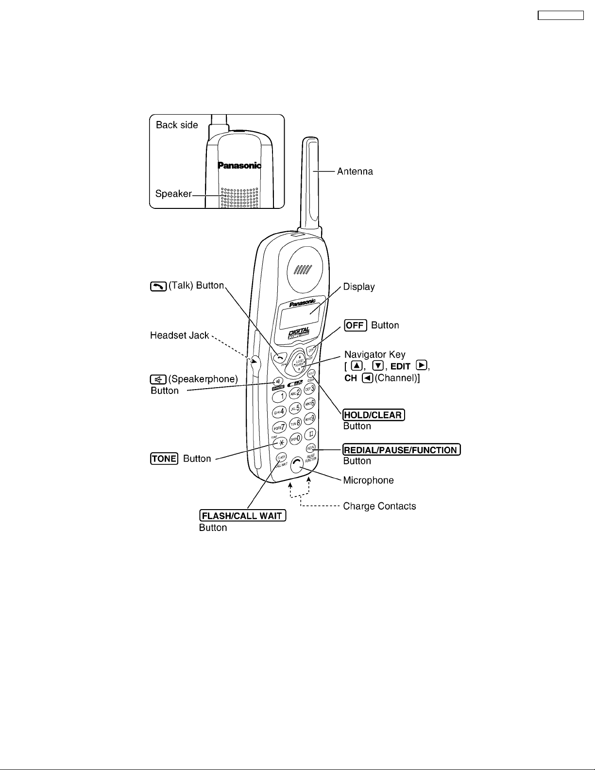
2.2. Handset
KX-TC1709LBB
7
KX-TC1709LBB
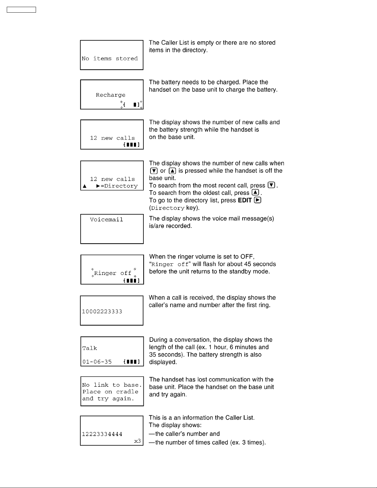
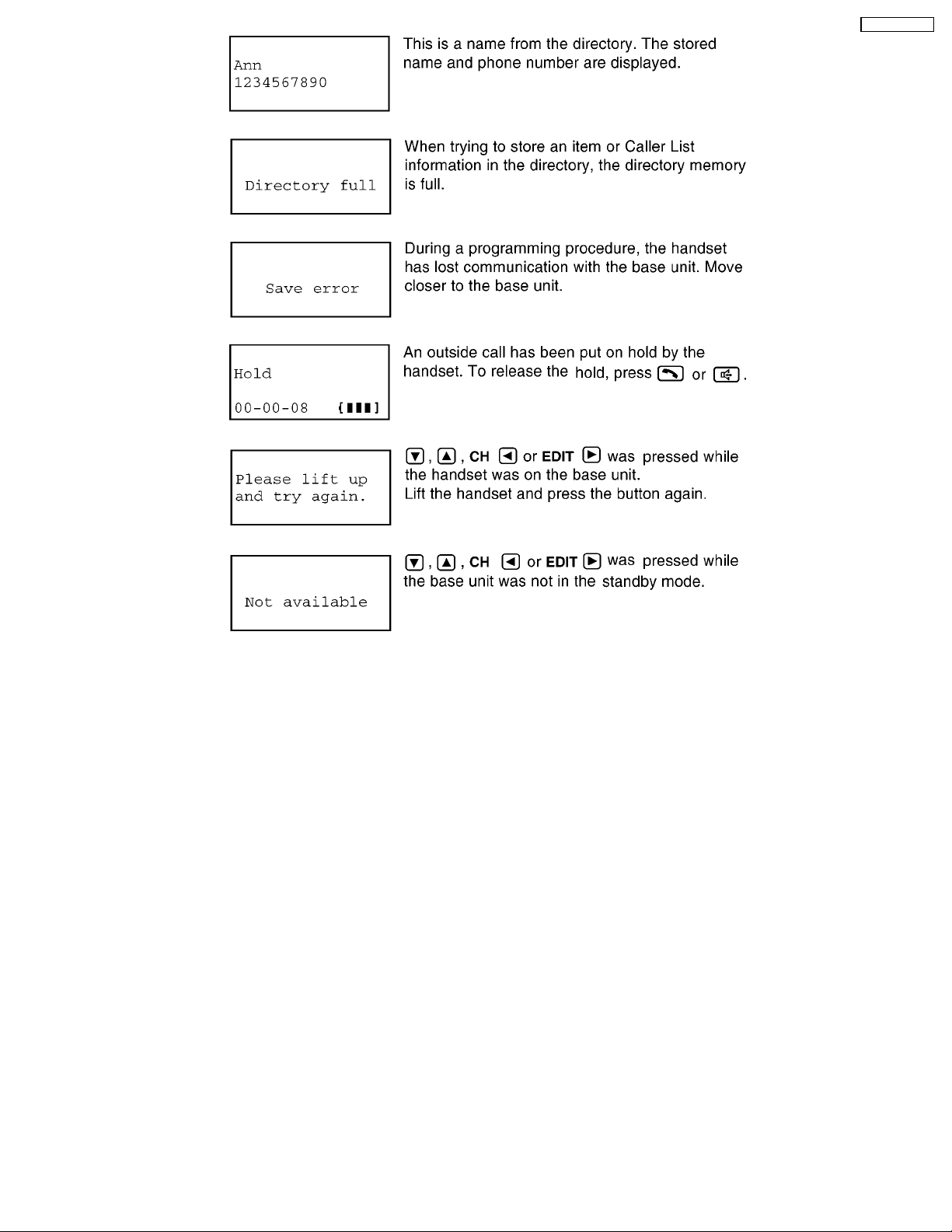
3 DISPLAY
The handset shows you instructions and information on the display. These display prompts are shown below.
8
KX-TC1709LBB
9
KX-TC1709LBB
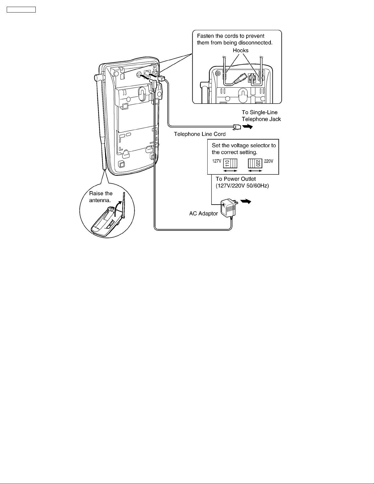
4 CONNECTIONS
Note:
· USE ONLY WITH Panasonic AC ADAPTOR PQLV2LBZ.
· The AC adaptor must remain connected at all times. (It is normal for the adaptor to feel warm during use.)
· If your unit is connected to a PBX which does not support Caller ID, you cannot access the service.
10
KX-TC1709LBB
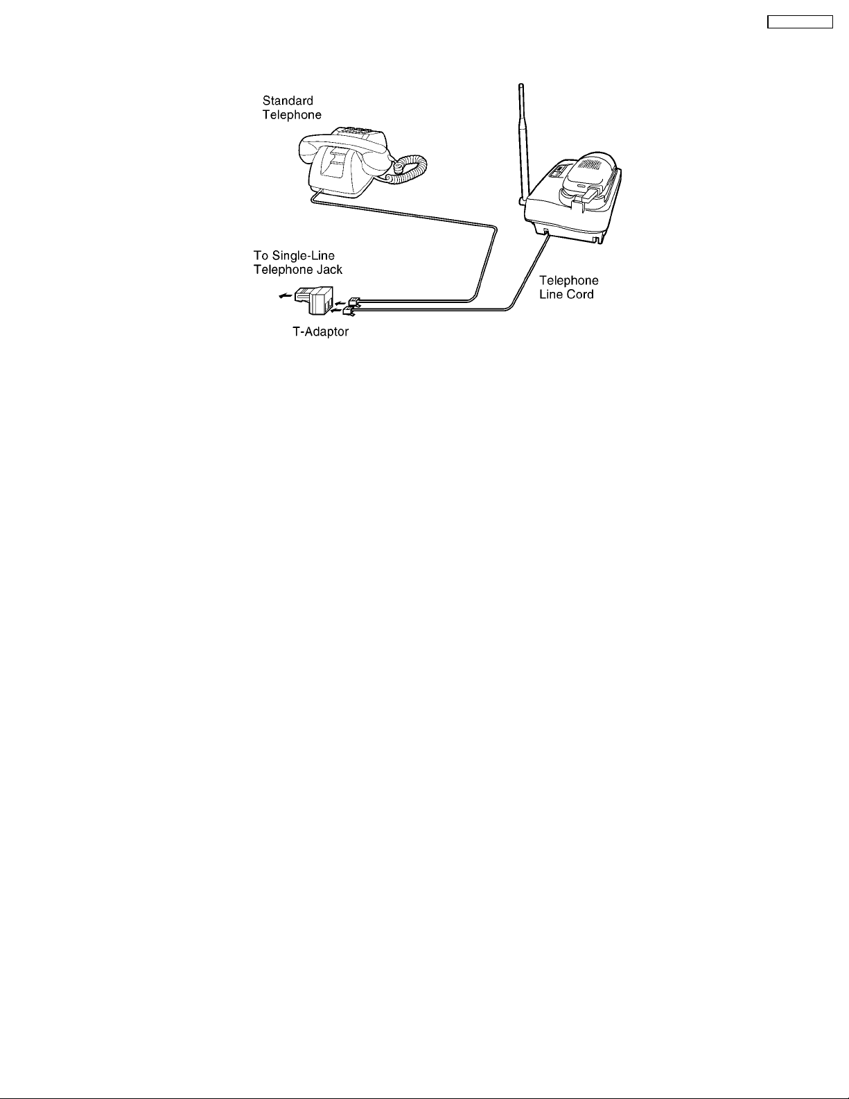
4.1. Adding Another Phone
This unit will not function during a power failure. To connect a standard telephone on the same line, use the Panasonic T-adaptor.
11
KX-TC1709LBB
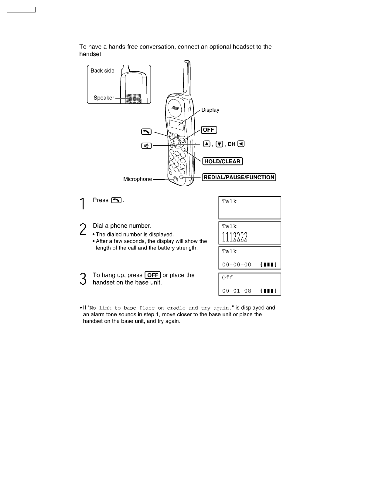
5 OPERATION
5.1. Making Calls
12
KX-TC1709LBB
13
KX-TC1709LBB
14
KX-TC1709LBB
15
KX-TC1709LBB
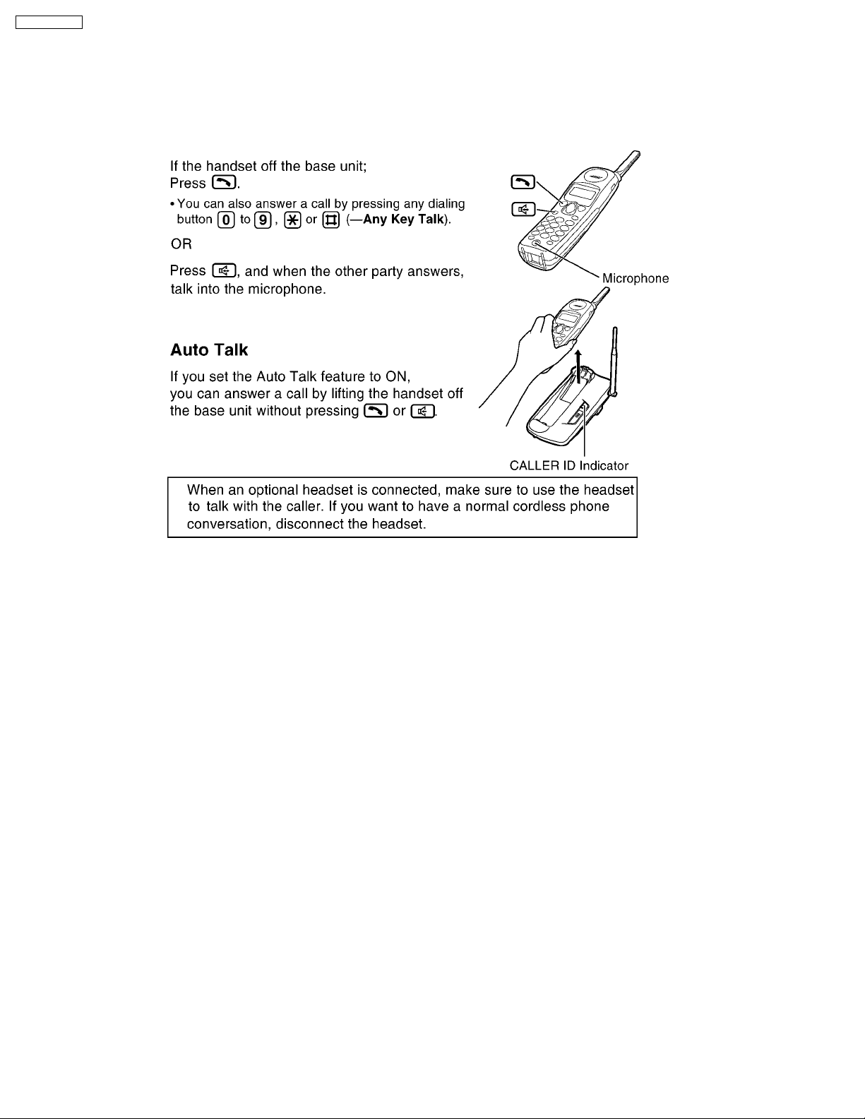
5.2. Answering Calls
When a call is received, the unit rings and the CALLER ID indicator on the base unit flashes quickly. If you subscribe to a Caller
Display service, the calling party information will be displayed after the first ring. In order to view the Caller ID information,
please wait until the second ring to answer a call.
5.2.1. With the Handset
16
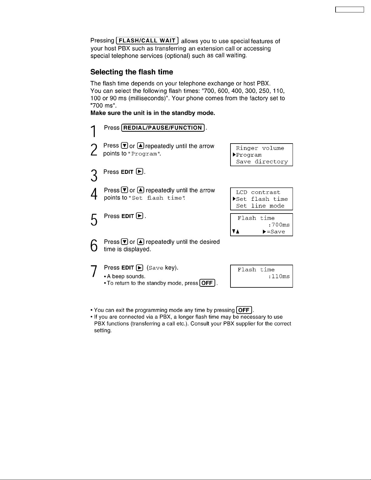
5.3. FLASH Button
KX-TC1709LBB
17
KX-TC1709LBB
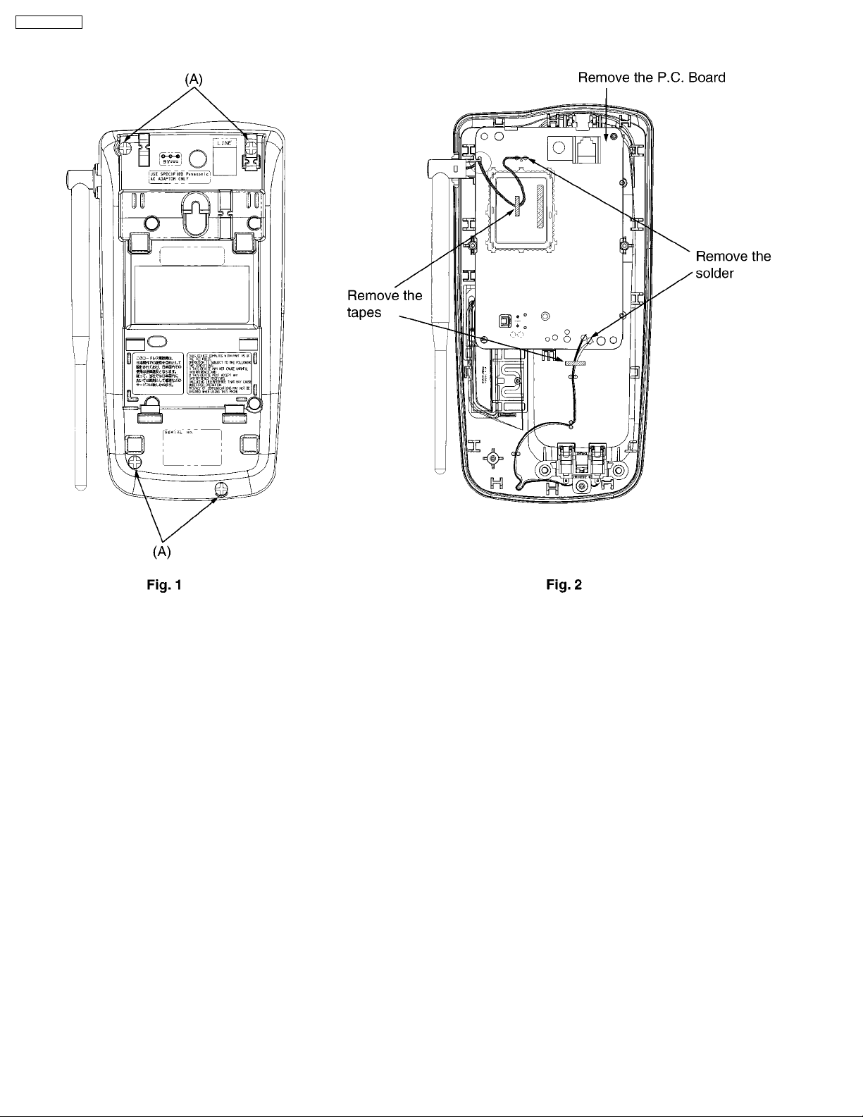
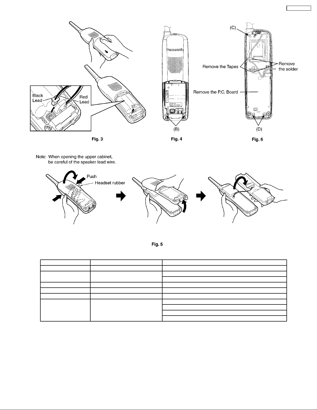
6 DISASSEMBLY INSTRUCTIONS
18
KX-TC1709LBB
Shown in Fig. To Remove Remove
1 Lower Cabinet Screws (2.6 X 12).....(A) × 4
2 Main P.C. Board Tapes and solder
Main P.C. Board
3 Battery Cover Battery Cover
4 Rear Cabinet Screws (2.6 X 12).....(B) × 2
5 Rear Cabinet Rear Cabinet
6 Main P.C. Board Screw (2.6 × 12).....(C) × 1
Screws (2.6 × 10).....(D) × 2
Lead wire
Main P.C. Board
19
KX-TC1709LBB
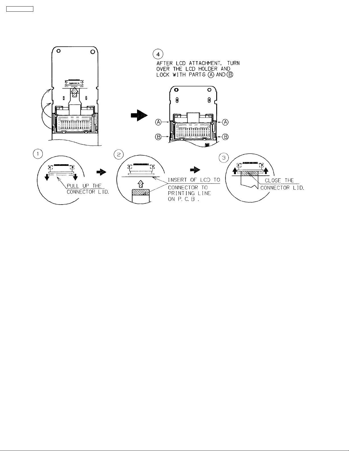
7 ASSEMBLY INSTRUCTIONS
7.1. Assembly the LCD to P.C. Board (Handset)
20
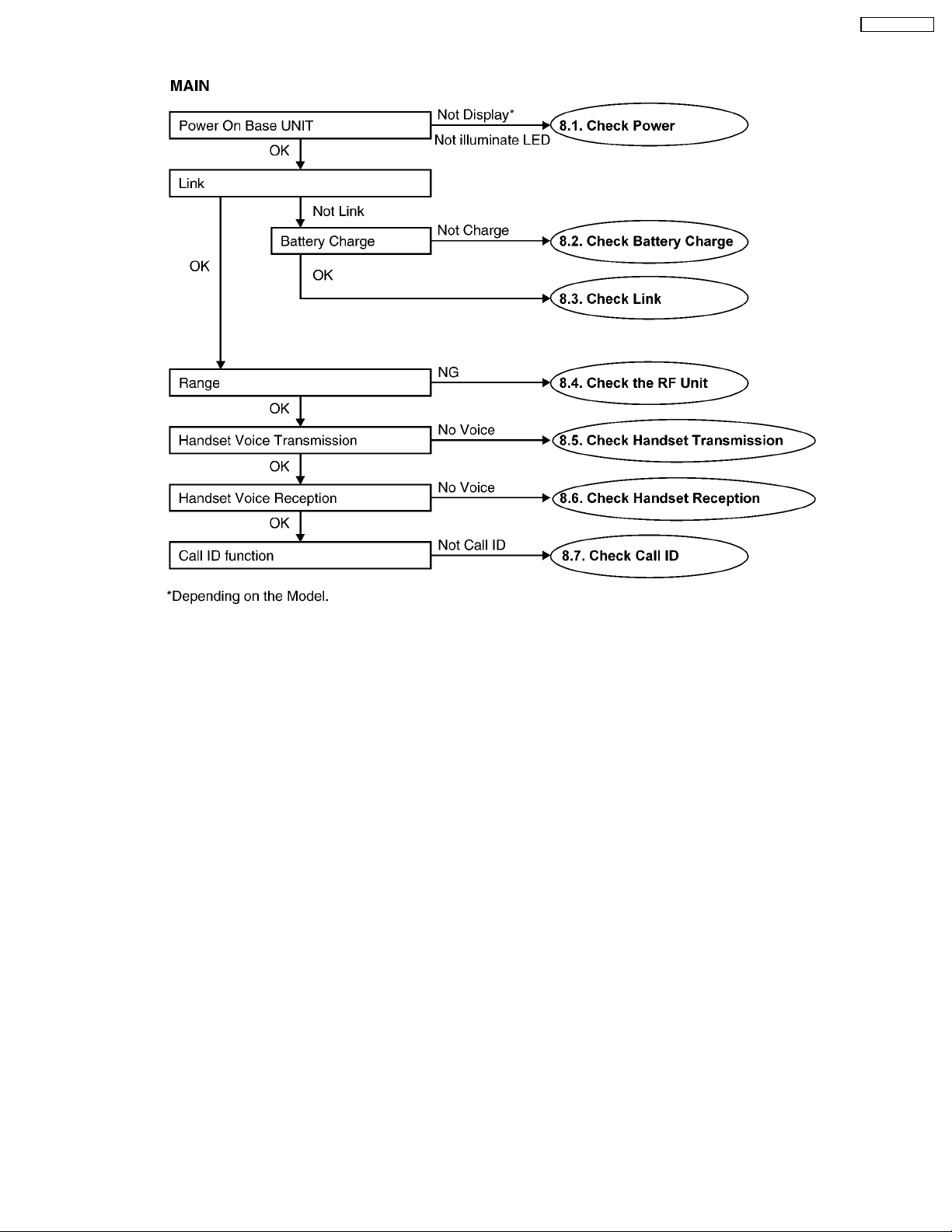
8 TROUBLESHOOTING GUIDE
KX-TC1709LBB
Cross Reference:
8.1. Check Power (P.22)
8.2. Check Battery Charge (P.23)
8.3. Check Link (P.23)
8.4. Check the RF Unit (P.24)
8.5. Check Handset Transmission (P.29)
8.6. Check Handset Reception (P.29)
8.7. Check Call ID (P.29)
21
KX-TC1709LBB
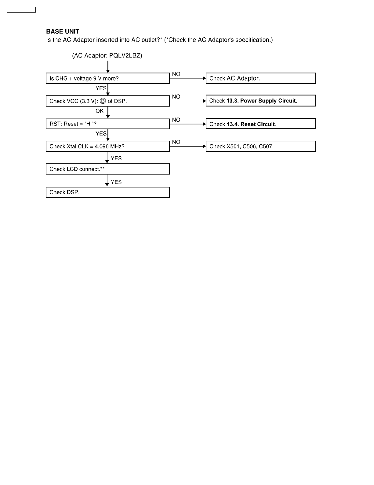
8.1. Check Power
Cross Reference:
13.3. Power Supply Circuit (P.40)
13.4. Reset Circuit (P.41)
NOTE:
EEPROM is IC551.
DSP is IC501.
** Models with no LCD can skip.
22
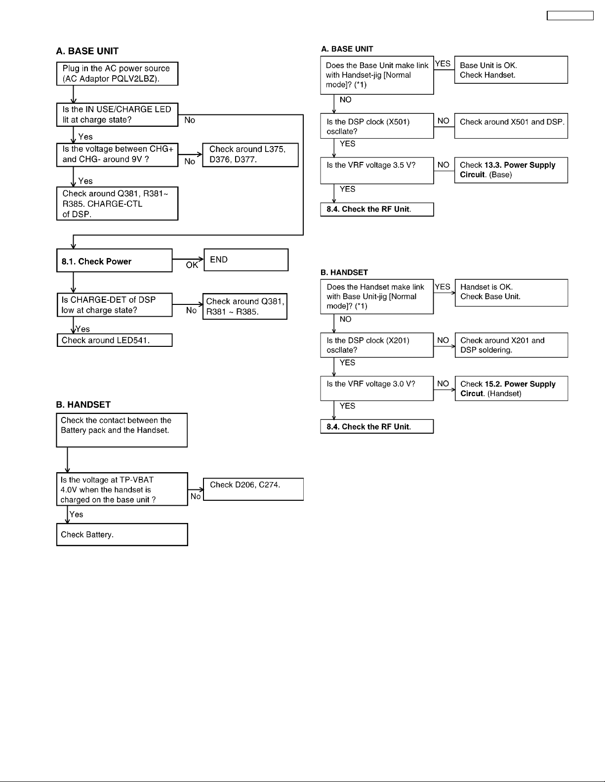
8.2. Check Battery Charge
KX-TC1709LBB
8.3. Check Link
NOTE:
EEPROM is IC551.
DSP is IC501.
NOTE:
EEPROM is IC551.
DSP is IC501.
Cross Reference:
8.1. Check Power
(P.22)
(*1) Refer to
Cross Reference:
8.4. Check the RF Unit
13.3. Power Supply Circuit
15.2. Power Supply Circuit
8.4.1. Finding out the Defective Unit
(P.24).
(P.24)
(P.40)
(P.48)
23
 Loading...