

Panasonic KX-TC1468LBB Service Manual
ORDER NO. KM40206883C3
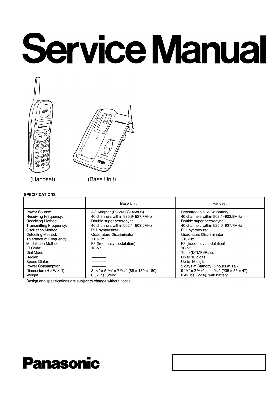
Telephone Equipment
KX-TC1468LBB
900MHz Cordless Phone
Black Version
(for Brazil)
© 2002 Kyushu Matsushita Electric Co., Ltd. All
rights reserved. Unauthorized copying and
distribution is a violation of law.

KX-TC1468LBB
CONTENTS
Page Page
1 STANDARD BATTERY LIFE 4
1.1. Recharge 4
1.2. Battery Information
2 LOCATION OF CONTROLS 5
2.1. Base unit 5
2.2. Handset
2.3. Battery Replacement
3 CONNECTIONS 7
3.1. Adding Another Phone 9
4 OPERATIONS 10
4.1. Making Calls 10
4.2. Answering Calls
5 DISASSEMBLY INSTRUCUTIONS 11
6 HOW TO REMOVE TEL JACK
7 TROUBLESHOOTING GUIDE
7.1. Check Power 15
7.2. Bell Reception
7.3. Check Battery Charge
7.4. Check Link
7.5. Check Handset Transmission
7.6. Check Handset Reception
8 ADJUSTMENTS (BASE UNIT) 21
10
13
14
16
17
18
20
20
4
5
6
8.1. Test Mode Flow Chart (Base Unit) 21
8.2. Adjustment
8.3. Adjustment Standard (Base Unit)
9 ADJUSTMENTS (HANDSET) 25
9.1. Test Mode Flow Chart (Handset) 25
9.2. Adjustment
9.3. Adjustment (Handset)
10 FREQUENCY TABLE (MHz) 29
11 BLOCK DIAGRAM (Base Unit)
12 CIRCUIT OPERATION
12.1. Outline 31
12.2. Power Supply Circuit
12.3. Reset Circuit
12.4. Charge Circuit
12.5. Telephone Line Interface
12.6. Transmitter/Receiver
12.7. Signal Route
13 BLOCK DIAGRAM (Handset) 36
14 CIRCUIT OPERATION (HANDSET)
14.1. Outline 37
14.2. Reset Circuit/Charge Circuit
14.3. Battery Low / Power Down Detector
22
23
26
27
30
31
31
32
33
34
34
35
37
37
38
2
KX-TC1468LBB
15 HOW TO REPLACE FLAT PACKAGE IC 39
15.1. Preparation 39
15.2. Procedure
15.3. Modification Procedure of Bridge
39
39
16 CPU DATA (Base Unit) 40
16.1. IC3 40
16.2. Digital Security Coding System
40
17 CPU DATA (Handset) 41
17.1. U1 41
18 EXPLANATION OF IC TERMINALS (RF Unit) 42
18.1. IC1 42
19 CABINET AND ELECTRICAL PARTS LOCATION (BASE UNIT)
20 CABINET AND ELECTRICAL PARTS LOCATION (HANDSET)
21 ACCESSORIES AND PACKING MATERIALS
43
44
45
22 TERMINAL GUIDE OF THE ICs TRANSISTORS AND DIODES
46
22.1. Base Unit 46
22.2. Handset
46
23 REPLACEMENT PARTS LIST 47
23.1. Base Unit 47
23.2. Handset
23.3. Accessories and Packing Materials
50
52
24 FOR SCHEMATIC DIAGRAM 53
24.1. Base Unit 53
24.2. Handset
53
25 SCHEMATIC DIAGRAM (Base Unit) 54
25.1. Main 54
25.2. RF Module
55
26 SCHEMATIC DIAGRAM (Handset) 56
26.1. Main 56
26.2. RF Module
57
27 CIRCUIT BOARD (Base Unit) 58
27.1. Main (Component View) 58
27.2. Main (Flow Solder Side View)
27.3. Locator (Component View)
27.4. Locator (Flow Solder Side View)
27.5. RF Module
59
60
60
61
28 CIRCUIT BOARD (Handset) 62
28.1. Main (Component View) 62
28.2. Main (Flow Solder Side View)
28.3. RF Module
63
64
3

Operation
Operating time
KX-TC1468LBB
1 STANDARD BATTERY LIFE
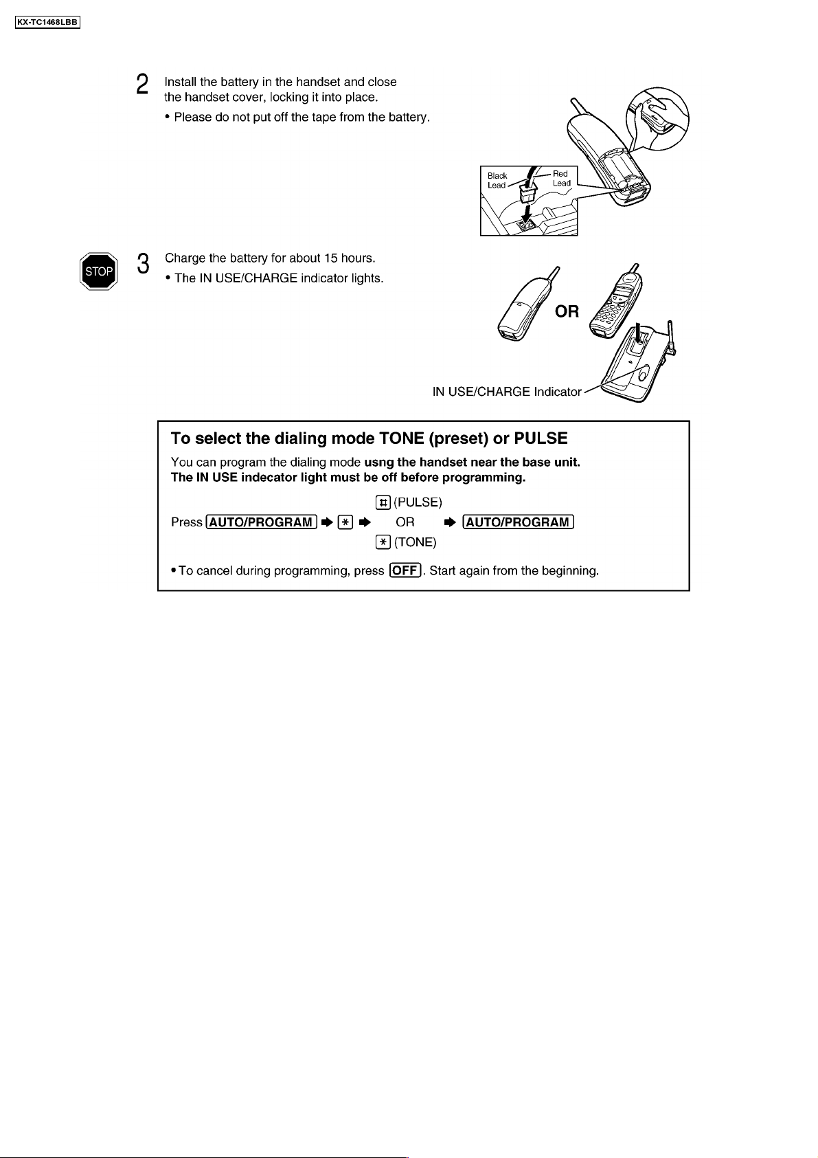
1.1. Recharge
1.2. Battery Information
After your Panasonic battery is fully charged:
While in use (TALK) Up to about 5 hours
While not in use (Standby) Up to about 5 days
· The battery operating time may vary depending on usage conditio ns and ambient temperature.
· Clean the handset and the base unit charge contacts with a soft, dry cloth. Clean if the unit is subject to grease, dust
or high humidity
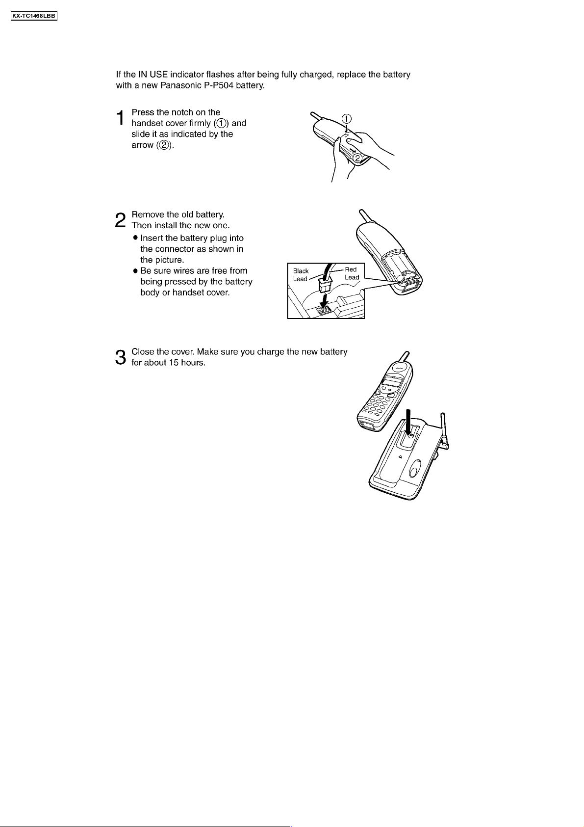
· If the battery is fully charged, you do not have to place the handset on the base unit until the IN USE indicator flashes. This will
maximize the battery life.
· The battery cannot be overcharged.
. Otherwise the battery may not charge properly.
4

2 LOCATION OF CONTROLS
2.1. Base unit
KX-TC1468LBB
2.2. Handset
5
KX-TC1468LBB
2.3. Battery Replacement
6
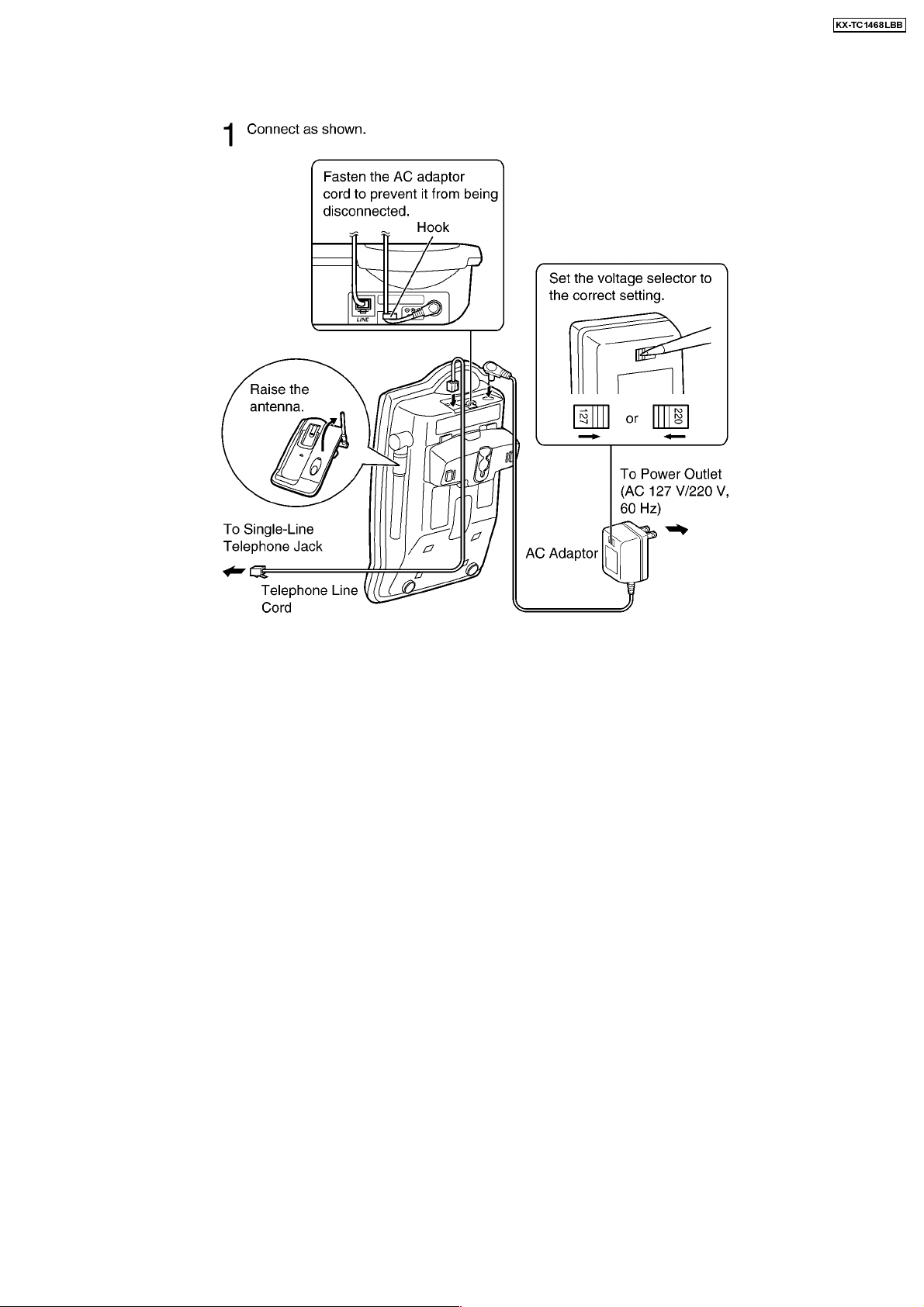
3 CONNECTIONS
KX-TC1468LBB
· USE ONLY WITH Panasonic AC ADAPT OR PQWATC1468LB.
· The AC adaptor must remain connected at all times. (It is normal for the adaptor to feel warm during use.)
7
KX-TC1468LBB
8
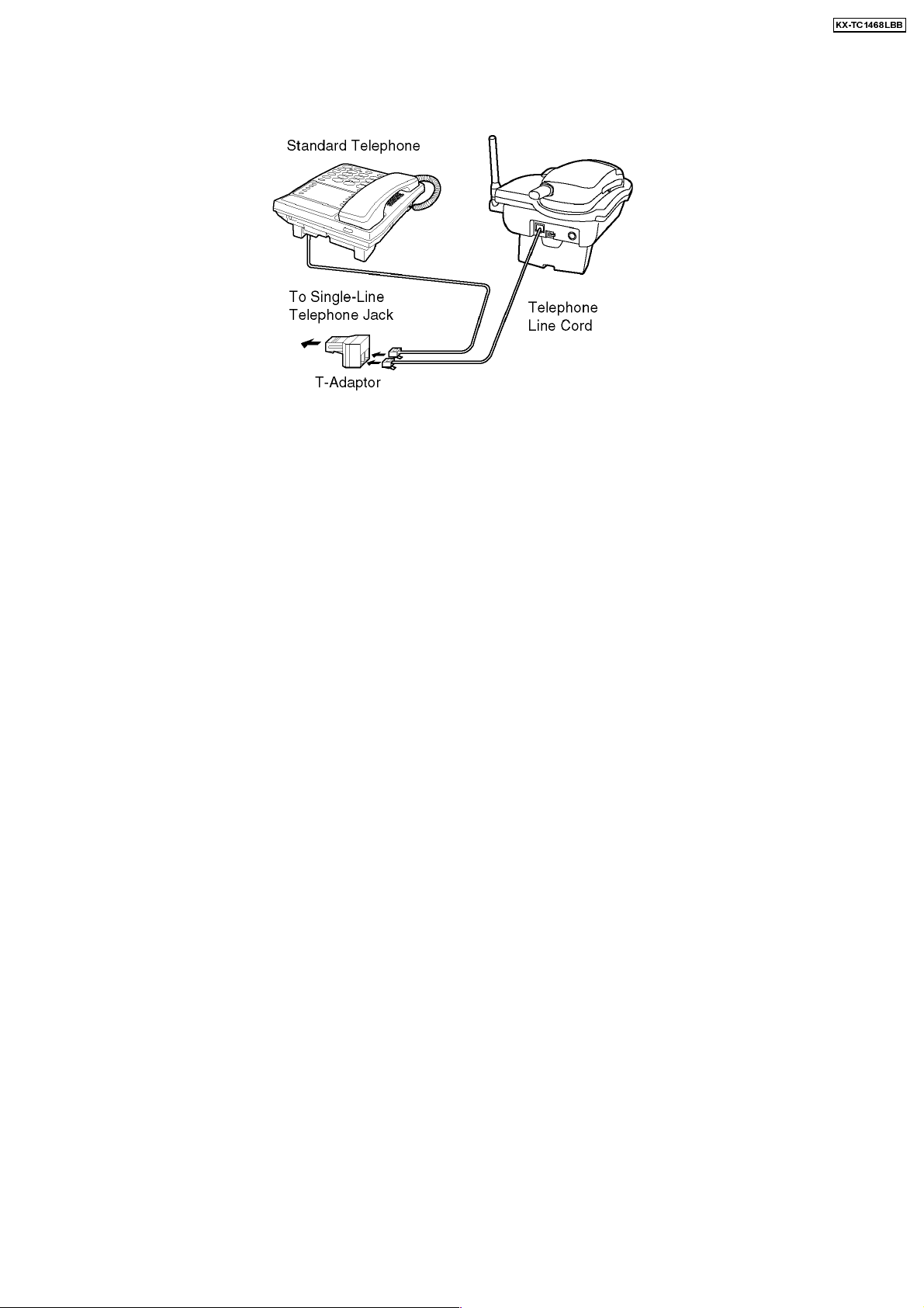
3.1. Adding Another Phone
This unit will not function during a power failure. To connect a standard telephone on the same line, use a T-adapto r.
KX-TC1468LBB
9
KX-TC1468LBB
4 OPERATIONS
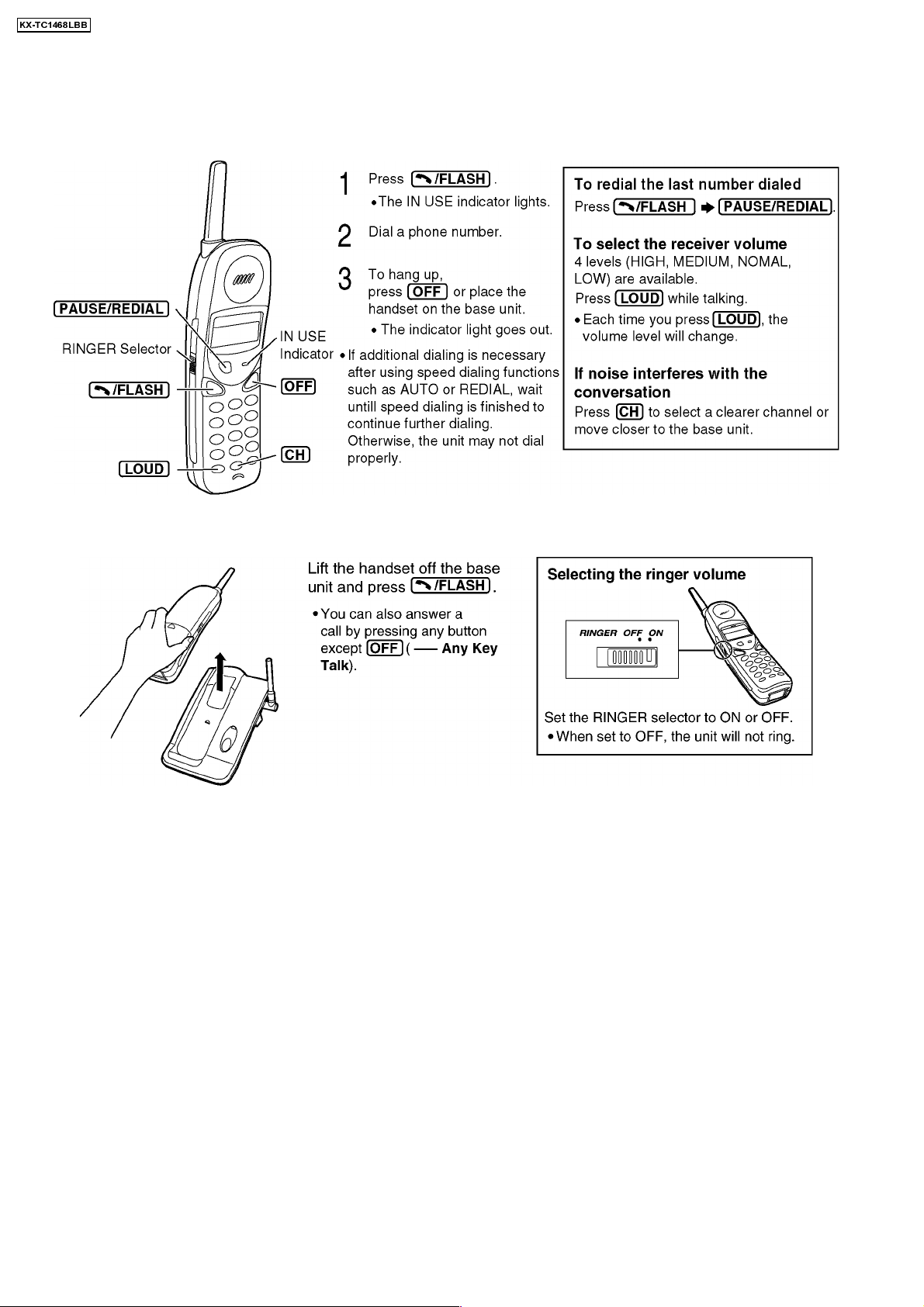
4.1. Making Calls
4.2. Answering Calls
10
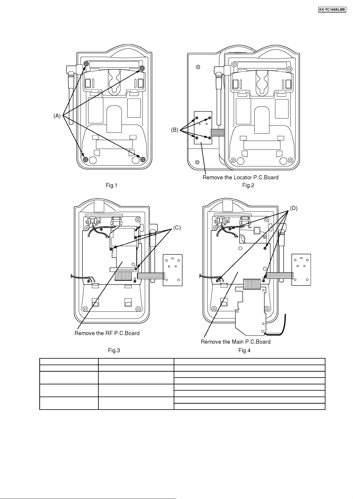
5 DISASSEMBLY INSTRUCUTIONS
Show in Fig.
To remove.
Remove.
KX-TC1468LBB
1 Lower Cabinet Screws (2.6 × 8)................ ....... (A) × 4
2 Locator P.C.Board Screws (2.3 × 6)................ ....... (B) × 4
Locator P.C.Board
3 RF P.C.Board Screws (2 × 6)................ ....... (C) × 3
RF P.C.Board
4 Main P.C.Board Screws (2.3 × 6)................ ....... (D) × 4
Main P.C.Board
11

Show in Fig.
To remove.
Remove.
KX-TC1468LBB
5
6 Screws (2.6 × 8)................ ......(E) × 2
Rear Cabinet
Battery compartment cover.
7
8 Antenna Screw (2.6 × 8)................ ......(F) × 1
RF P.C.Board Screws (2 × 6)................ ......(G) × 2
RF P.C.Board.
9 Main P.C.Board Screws (2 × 6)................ ......(H) × 2
Main P.C.Board
12
KX-TC1468LBB
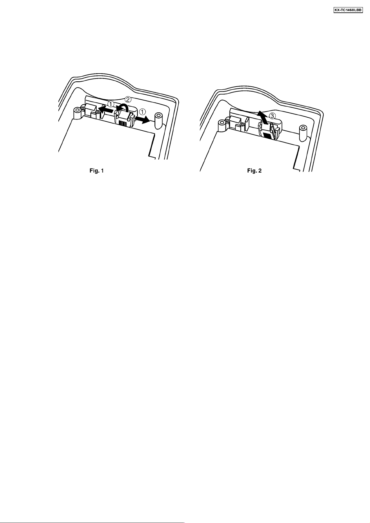
6 HOW TO REMOVE TEL JACK
1. Keep 2 hooks for TEL JACK fixing open in the direction of arrow 1, then pull the top of TEL JACK forward as shown arrow 2
until the hooks click. (Refer to
2. Remove TEL JACK pulling just above in the direction of arrow 3. (Refer to
Fig. 1.)
Fig. 2.)
13
KX-TC1468LBB
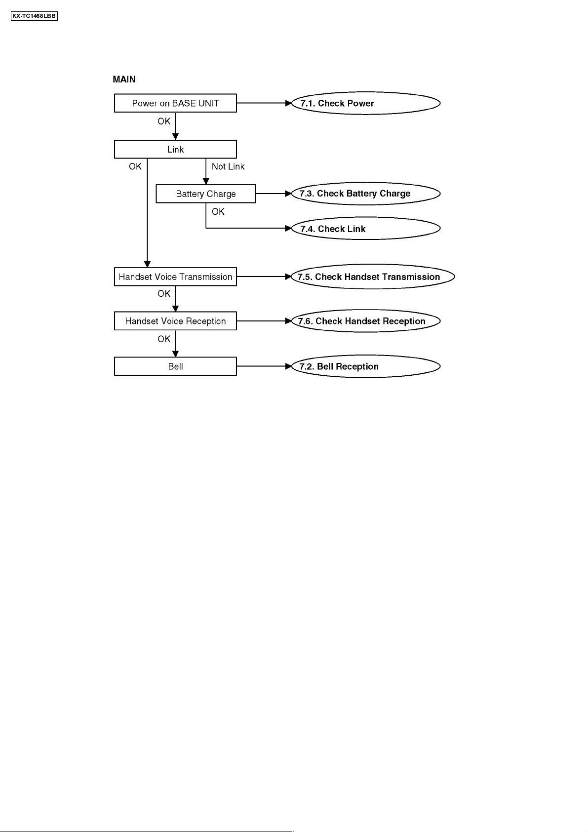
7 TROUBLESHOOTING GUIDE
Cross Reference:
Check Power
Bell Reception (P.16)
Check Battery Charge (P.17)
Check Link (P.18)
Check Handset Transmission (P.20)
Check Handset Reception (P.20)
(P.15)
14
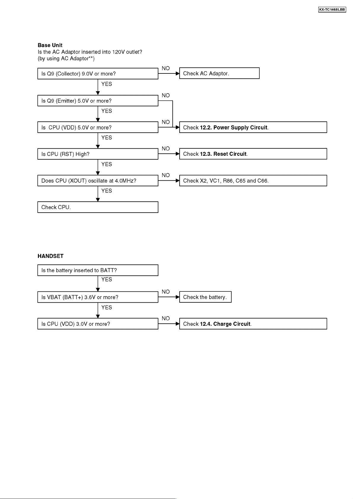
7.1. Check Power
KX-TC1468LBB
Cross Reference:
Reset Circuit
Power Supply Circuit (P.31)
** :
CONNECTIONS (P.7)
Cross Reference:
Charge Circuit
* : Each measurement points are shown in CIRCUIT BOARD (Base Unit) (P.58) or CIRCUIT BOARD (Handset) (P.62)
(P.32)
(P.33)
Note:
CPU: IC3
Note:
CPU: U1
15
KX-TC1468LBB
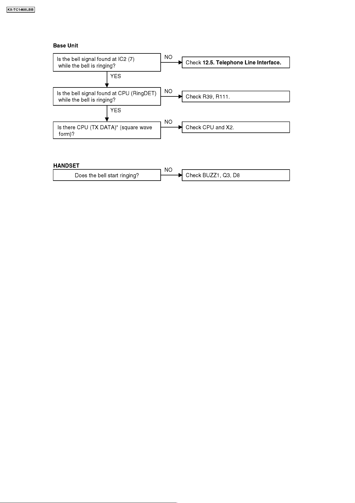
7.2. Bell Reception
Cross Reference:
Telephone Line Interface
* : Each measurement points are shown in CIRCUIT BOARD (Base Unit) (P.58) or CIRCUIT BOARD (Handset) (P.62)
(P.34)
Note:
CPU : IC3
16
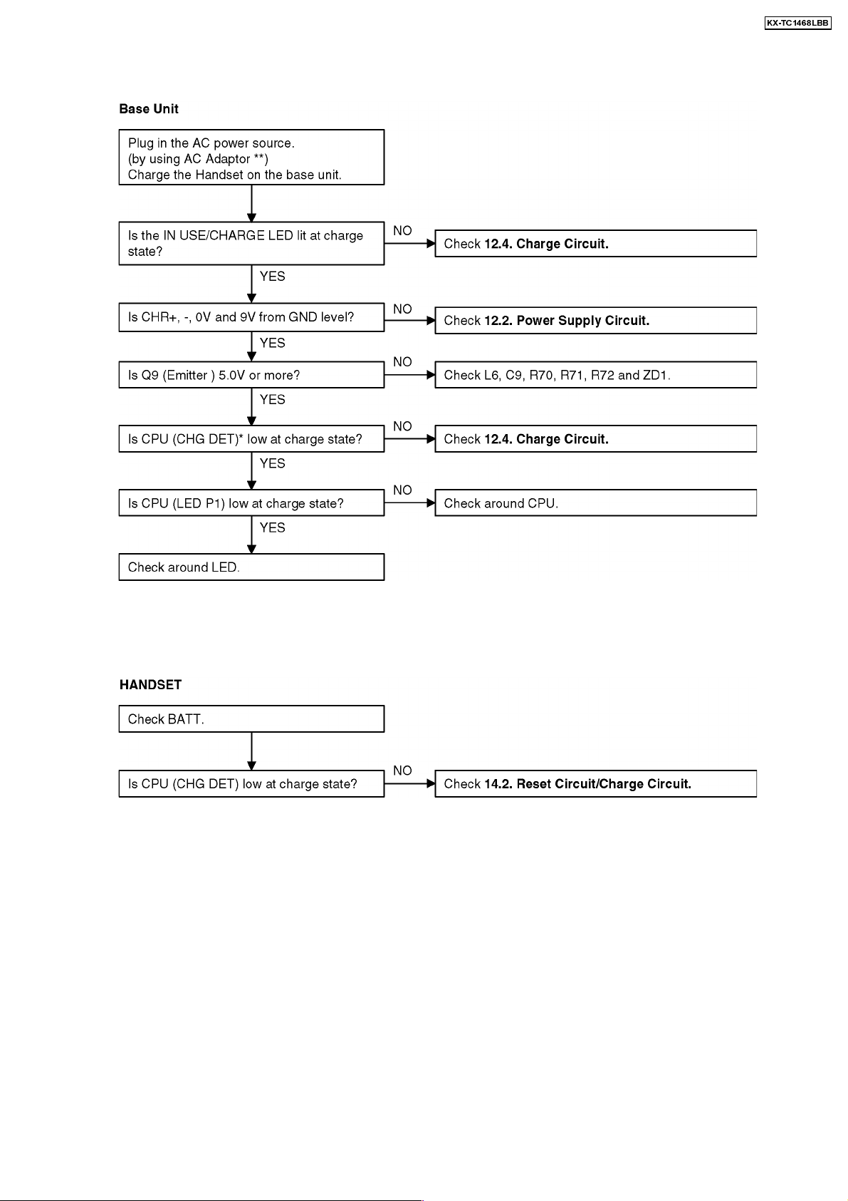
7.3. Check Battery Charge
KX-TC1468LBB
Cross Reference:
Charge Circuit
Power Supply Circuit (P.31)
** :
CONNECTIONS (P.7)
Cross Reference:
Reset Circuit/Charge Circuit
*: Each measurement points are shown in CIRCUIT BOARD (Base Unit) (P.58) or CIRCUIT BOARD (Handset) (P.62)
(P.33)
(P.37)
Note:
CPU: IC3
Note:
CPU: U1
17
KX-TC1468LBB
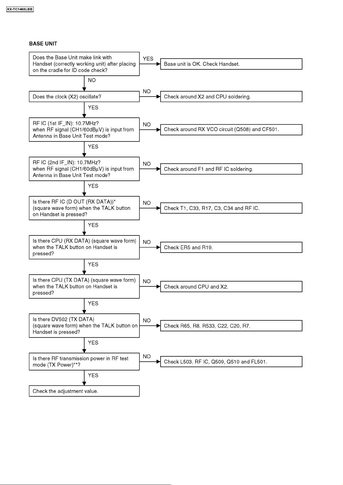
7.4. Check Link
**: Refer to Adjustment (P.22) Note:
CPU: IC3
RF IC: IC1
*: Each measurement points are shown in CIRCUIT BOARD (Base Unit) (P.58) or CIRCUIT BOARD (Handset) (P.62)
18
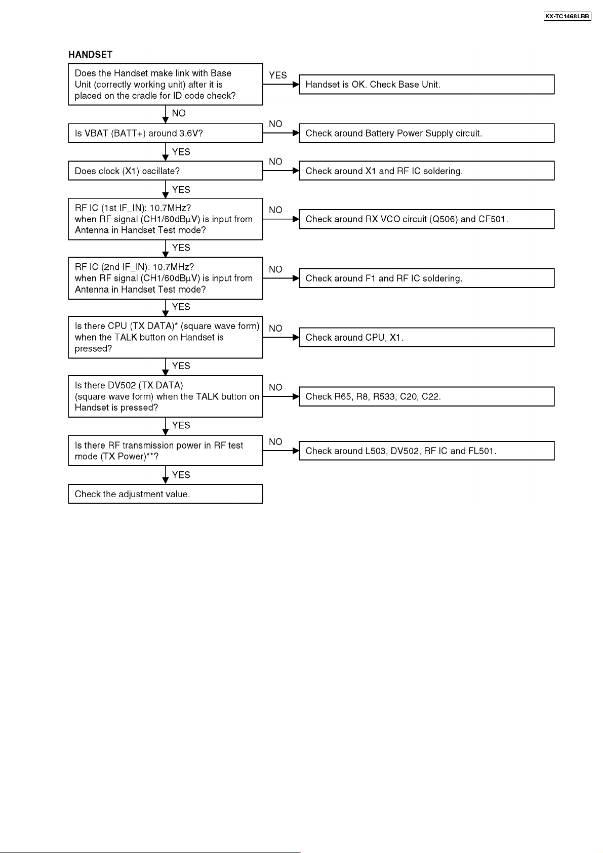
KX-TC1468LBB
**: Refer to Adjustment (P.26). Note:
CPU: U1
RF IC: IC1
*: Each measurement points are shown in RF Module (P.64)
19
KX-TC1468LBB
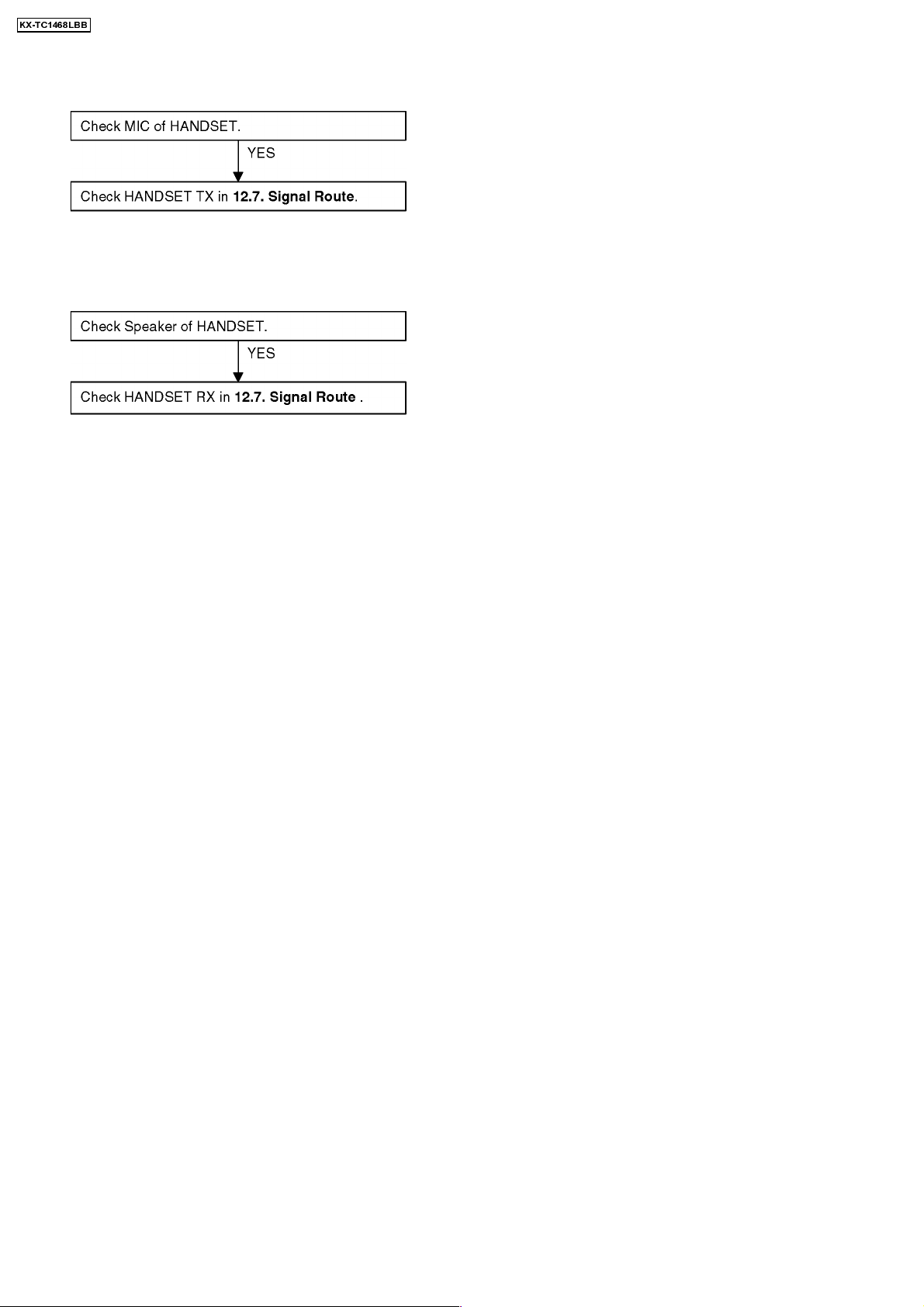
7.5. Check Handset Transmission
Cross Reference:
Signal Route
(P.35)
7.6. Check Handset Reception
Cross Reference:
Signal Route
(P.35)
20
 Loading...