Supports toll restriction, day/night service, and flexible assigned incoming/outgoing dialing.
Serial Interface: Is RS-232C for connection of printer
Back-up Battery: Is rechargeable with replacement after owing it for 5 years.
Speaker amplifier with on music on hold
Power Supply: Requires AC connection
Frequently Asked Questions
Q: What is the maximum number of extensions that can connect to the KX-T61610?
=A: The units virtually supports maximum of KX T61610 16 extensions maximum
Q: Is it possible to attach regular telephones to this system?
A: Regular phones are attachable with appropriate modular jacks.
Q: Does KX-T61610 contain an answering machine?
A: The device does not include answering machines but allows the integration of answering machines.
Q: When can I do the programming for the system?
A: This can be done by using extension 11.
Q: What if the phone does not work after it has been installed?
A: Please ensure power switches are turned on and connections are made properly. If issues persist, the guidelines of the installation kit should be adhered to or professionals approached.
Q: Are there provision for alternative power sources in case of power outages?
A: You have the option of connecting a system backup unit (KX-A16) for battery back-up.
Q: How frequently is the back up battery supposed to be replaced?
A: This should be done every 5 years.
User Manual
Page 1
ELECTRONIC MOhJLAR SWITCHING SYS,TEM
Panasonic
Please read this manual before connecting the KX-T61610.
Quick Reference Card for Standard Telephone can be found on pages.+22 through 6-29. _ .
Page 2
Thank you for purchasing the Panasonic Model KX-T61610,
Electronic Modular Switching System (EMSS).
System Component
Service unit
Telephone
Optional
equipment
Model No.
KX-7-61610 Electronic Modular Switching System
KX-T61620
KX- 7-61630
KX- T61650
KX- T61640
KX-T30860D(only) Doorphone Adaptor
KX- T30865 Doorphotze
KX- T30890 Headset
KX-Al6 System Back-up Unit
EMSS Proprietary TelephotleEMSS Proprietary Telephorze with LCD
EMSS Proprietary Telephone
DSS Console
Description
..___
l-l
Page 3
NOTIFY THE TELEPHONE COMPANY
Installation must be performed by the telephone company or a qualified professional
installer.
Notify the Telephone Company
Before connecting this equipment to any telephone, call the telephone company and
inform them
Push Buttons A and B simultaneously to open Front Cover.
y-Jtariotl
IT-I
3
1
7
0
“I
I 0
L-zz-
*Power SwiWh
Modular Jacks
Reset Button
System Program Switch
0
--
Page 9
INSTALLATION
Installation
Cautions
*Avoid insralling in the following places. (Doing so may resulr in malfunction, noise, or discoloration.)
1. In direct sunlighr and her, cold, or humid places. (Temperarure range: 32”F-104°F)
2. Sulfuric gases produced .in areas where there are thermal springs, etc. may damage the equipment or
contacls.
3.
Places in which shocks or vibrations are frequent or strong.
4.
Dusty places, or places where water or oil
5. Near high-frequency sewing machines or electric welders.
6. On or near computers, relexes, or other office equipmenr, as well as microwave ovens or air condirioners.
(Ir is preferable not lo install in the same room with the above equipment.)
7. Near radio broadcast anlennas (including short wave).
8. Insrall at least 6
proprierary telephones)
9. Do not obslrucr area around (he electronic modular swirching system.
inspecrion-be especially careful lo allow space
swirchitig sysrem)
feet
from radios and relevisiotls. (both rhe electronic modular switching system and EMSS
may
come into contact with the unit.
(for reasons of nlaitlfetlatlce atId
for
cooling above and at rhe sides
of
the electronic modlilar
Cautions
1. Do not wire the telephone cable in parallel with the AC power source, computer, telex efc.
near rhose wires, shield the cables with metal tube ‘or use shield cables and ground the shields.
2. When cables run on the floor, use protectors or the like lo protect the wires where they may be stepped on.
Avoid wiring under carpets.
3. Avoid using the same AC 120 V power supply outlet
Otherwise, the KX-%1610’s system operation may be interrupted by the inducrion noise from such
C. .-T. .”
When console 1 has been stored to exten-
sion 12, the pair telephone with the console
1 has been stored to extension 13, the
console 2 has been stored to extension 14
and the pair telephone with console 2 has
been stored to extension 15, “C12-T13,
C14-T15” will be displayed.
3. Dial the extension nlonber to which the
console 1 is connected.
4. Press the “ 0 ” button.
when nothing is stored.
l l
-T
l l
Conditions
l DSS console can be connected up to two.
0 DSS console can not be connected in pair wit
a standard telephone.
0 DSS console can not be connected at extensio
11.
Example:
If
Mr Jay’s secretary has KX-T61630 at exten-
sion 12 and is to use the DSS console (KX-
,
T&640), the console should be connected to
extension 13. (Paired extension is ext. 12.) Mr
Brown’s secretary has KX-T61620 at extension
14 and is to use the DSS console (KX-T61640),
the console should be connected to extension 15.
(Paired extension is ext. 14.)
Programming Table
See page 6-14.
5. Dial the extension number which is paired
with the console 1.
‘If
you don’t connect the console 2, pro-
ceed to step 10.
6. Press the “ 0 ” button.
7. Dial the extension number to which the
console 2 is connected.
8.
Press the ‘I 0 ” button.
9. Dial the extension number which is paired
with the console 2.
10.
Press the MEMORY button.
11.
To return to the initial program mode, press
the END button.
3-9
Page 33
r
:_.~.*~--~.~~ Ltrrtil the desired CO number appears
:
[03] [NEXT] [w] [SELECT] [MEYORY] [END]
or
[03] [NEXT] [Al [SELECT] [MEMORY] [END]
T I
;_ _____ .__ ____
Description
You can program which outside line is con?,
netted and which one is not connected. .
When an extemion automatically selects ali idle
outside line, the extetlsioll can be connected to it
quickly.
A=*: to &sign the same on all 6 CO’s
1:
0nCOI
Conditions
l
When you start the programming from step 1,
::
yowl may
of the NEXT button at step 3.
l
The PREV btctton allows you to see the entr)
status iti the previous CO cotinectio~i assigriment.
dial the desired CO number instead
Programming
1.
Dial (03).
“CO CONNECTION” will be displayed.
2. Press the NEXT button.
“ENTER CO NO” will be displayed.
3.
Press the NEXT button.
“CO 1: CONNECT” will be displayed and
“CONNECT” will blink.
4. Press the SELECT button, to alternate between CONNECT and NO CONNECT to
select the desired mode.
5. Press the MEMORY button.
The LCD -will stop blinking.
6. Repeat steps 3 to 5, to program the dialing
mode on the other CO lines.
7.
To return to the initial program mode, press
the END button.
3-10
Example:
CO 1 and 2 . . . . . , . . . . . . . . . CONNECT
CO 3
1. [03] [NEXT] [(NEXT)
2.
3.
. . . . . . . . . . . . . . . . . . NOCONNECT
or
(l)] [MEMORY]
[NEXT] [MEMORY]
[NEXT] [SELECT] [MEMORY] [END]
Programming Table
See page
6-14.
Page 34
I~-~~---~-~~~--~ until the desired CO number appears
[0orq] [NEXT] [Al [SELECT] [MEMORY] [END]
pI’[+$]: to assign the same on all 6 CO’S
Description
Allows the user to select rhe dialing mode (tone
or pulse) of each CO (Central Ofice) line.
*TONE Dial Mode
The dial signal from rhe extension (ivith tone or
pulse dial mode) will be converted to TONE.
TONE will rhen be transmitted to the Cenrral
Office.
l
PlJLSE Dial Mode
The dial signal from rhe extension (with tone ot
p&e dial mode) will be converted to PULSE.
PULSE will then be transmitted to the Central
Ofice.
Programming
1. Dial (04).
“CO DIAL MODE” will be displayed.
2. Press the NEXT button.
“ENTER CO NO” will be displayed.
3. Press the NEXT button.
“CO 1: TONE”
“TONE” will blink.
4. Press the SELECT button fo alternate
tween TONE and PULSE.
5. Press the MEMORY butron.
-The LCD blinking will stop.
6. Repeat sreps 3 to 5, to progratn the dialing
mode on the other central ofice lines.
7. To return to rhe initial program mode. press
the END burton.
will be displayed and
be-
Conditions
0 When you start the programming frotn step 1,
you
may dial rhe desired CO number instead
of the NEXT button at step 3.
l
The PREV button allows you to see the entry
status in the previous CO dial mode.
‘If the KX-T61610 is connected lo rhe Central
Office directly or installed behind a host PBX,
which receives both tone and pulse dialing
mode, the KX-T61610 must be used only in
the lone dial mode.
‘If your extension is not a KX-T61630,
KX-T61620,
KX-T30820 or KX-T308SO but a standard
telephone, and the dial tone frequency of CO
Lines is 600 Hz, the KX-T61610 tnust be used
only for the pulse dial mode of CO Lines.
If you select the automatic switching mode for
daylnight service,
Refer to “Switching Mode (DaylNight Service)”
page 3-12.
enter the starting time.
Programming
1. Dial (06).
“DAY/NIGHT TIME” will be displayed.
Conditions
elf the NEXT button is pressed at step 3
through 7, the display will advance to the
“Night Time input” mode (step 9). The
operations of step 3 through 7 are not stored.
l
if
the PREV button is pressed at step IO
through 14, the display will return to the “day
time input” mode (step 2). The operations of
step 10 through 14 are not stored.
2. Press the NEXT button.
“DAY: 09:OO AM” will be displayed as a
default value and “09” will blink.
3. Enter the starting time for day service using 2
digits.
4. Press the “Q” button.
“00” will blink.
5. Enter the minute using 2 digits.
6. Press the “0” button.
“AM” will blink.
7. Press the SELECT button to alternate between “AM” and “PM” to select the correct
setting.
8. Press the MEMORY button.
9. Press the NEXT button.
“NIGHT: OS:00 PM” will be displayed as a
default value and “05” will blink.
A
Example:
8.30 AM...
6:30 PM. . . starting time for night plan
starting time for day plan
Programming Table
See page 6-14.
10. Enter the starting time for night service using
2 digits.
11. Press the “0” button.
“00” will blink.
12. Enter the minute using 2 digits.
13. Press the ‘IQ” button.
“PM” will blink.
14. Press the SELECT button to ,alternate between “AM” and “PM” to select the correct
setting.
1s. Press the MEMORY button.
16. To return to the initial program mode, press
the END button.
Page 38
;------------until the desired extension number
;-v’m’---- ,dial the CO number
; . . .‘.
..j !23&56+.;.. .,:;.;:.
,. (CLEAR) ‘, .,.
il
[07] [NEXT] [NEiT] & [MEMORY][END]
t
PO:] [NEXT] [AB] [C...E] [MEMOFiY][END]
-
appears
:.
:::,:;-” :,. :; . ..‘.‘-.
defaulf (all 16 &~eil&n~) :’
,,.’ .‘. . . ....
‘“--“-‘--‘---““-----~
Description
Through programming, you can select which
extensions may be used for outward dialing by
using the day mode
of
operation.
Programming
1. Dial (07).
“DAY: OUT CO” will be displayed.
2. Press the NEXT button.
“ENTER EXT NO” will be displayed.
3. Press the NEXT button.
“11: CO 12 3 4 5 6” will be displayed and “1
2 3 4 5 6” will blink.
4. Dial the CO number to be entered.
The desired combination
displayed.
To prohibit dialing, press the CLEAR button
instead
of the
CO number.
“11: CO.....” will be displayed.
of
CO
lines
AB=[*]:
will be
to assign the same on all16 extensions
Conditions
*When you start the programming from step 1,
you may dial the desired -extension. number
instead
@The PREV button allows you to go to the
previous extension
assignment.
Exanzple: COMPANY XYZ
Company XYZ wants only extension 11 and 15
to have access to CO 1, 2 and 3 on outgoing
calls during the day. Extensions 12, 13, 14, 16,
17 and 18 are to be programmed
only CO 1 and 2.
1. [07]
2. [NEXT] [I] [2] [MEMORY]
3. [NEXT] [l] [2] [MEMORY]
4. [NEXT] [l] [2] [MEMORY]
5. [NEXT] [l] [2] [3] [MEMORY]
6. [NEXT] [l] [2] [MEMORY]
7. [NEXT] [l] (21 [MEMORY]
8. [NEXT] fl] [2] [MEMORY] [END]
of
the NEXT button at step 3.
for
displaying the CO
[NEXT] [(NEXT) or (ll)] [l] [2] [3]
[MEMORY]
for access to
5. Press the MEMORY button.
The LCD will stop blinking.
6. Repeat steps 3 to 5, to program the assign-
ment on the other extensions.
7. To return to the initial program mode, press
the END button.
Programming Table
See page. 6-15.
- .
?-I<
Page 39
. . . . ..until the desired extension number appears
[08] [NEXT] (N:XT] [C...El [MEM,ORY][END]
;8] [NEXT] [ABI [C...E] [MEMORY][END]
to assign the same on all 16 extensions
Description Conditions
l
Through programming; you can select
extensions may be used
using the night mode
for
outward dialing by
of
operation.
Programming
1. Dial (08).
“NIGHT: OUT CO” will be displayed,
2. Press the NEXT button.
“ENTER EXT NO.” will be displayed.
3. Press the NEXT button.
“11: CO 12 3 4 5 6” will be displayed
2 3 4 5 6” will blink.
4. Dial the CO numbers to be entered.
The desired combination
displayed.
To prohibit dialing, press the CLEAR button
of
the CO number.
“11: CO.....” will be displayed.
of
CO lines will be
of which
n
: !
and “1
When you start the programming from step 1,
you may dial the desired extension number
instead
l
The PREV button allows you to go to the
previous
assignment.
Example: COMPANY XYZ
Company XYZ wants extensions 11, 13 and 16
to have access to CO 1, 2 and 3 on outgoing
calls during the night. Extensions 12, 14, 15, I7
and 18 are to be programmed
CO 1 and 2.
1. [08]
[MEMORY]
2. [NEXT] [l] [2] [MEMORY]
3. [NEXT] [l] [2] [3] [MEMORY]
4. [NEXT] [l] [2] [MEMORY]
5. [NEXT] [l] [2] [MEMORY]
6. [NEXT] [l] [2] [3] [MEMORY]
7. [NEXT] [I] (2) [MEMORY]
8. [NEXT] [l] [2] [MEMORY]
of
the NEXT button at step 3.
extension
[NEXT] [(NEXT) or (ll)] [l] [2] (31
for
displaying the CO
for access to only
[END]
5. Press the MEMO,RY button.
The LCD -will stop blinking.
6. Repeat steps 3 to 5, to program the assignment on the other extensions.
7. To return to the initial program mode, press
the END button.
3-16
Programming Table
See
page
6-15.
Page 40
O--------utltiI the desired extension number appears
,---.-.-.” ‘dial the CO number
[09] [NEXT] [NEXT] [C..‘.E] [MEMORY][END]
or
[09] [NEXTI [ABI [C...E] [MEMORY][END]
f
~.~-~.~~~.~~~~~~~---~-~~~ AB=[%]: to assign the same on all 16 extensions
. . . . . . . . . . .
default (all 16 extensions)
Description
Through programming, you can select which
extensions will ring on incoming calls from rhe
Central Ofice during the day time.
Programming
1. Dial (09).
“DAY: IN CO” will be displayed.
2. Press the NEXT button.
“ENTER EXT NO” will be displayed.
3. Press the NEXT button.
“11: CO 1 2 3 4 5 6” will
2 3 4 5 6” will blink,
4. Dial the CO numbers to be entered.
The desired combination of CO lines will be
displayed.
To prohibit ringing, press the CLEAR but-
ton insread of the CO number.
“11: CO.....” will be displayed.
I
be displayed and “1
Conditions
0 When you start
you may dial the desired extension number
instead of the NEXT button at step 3.
eThe PREV button allows. you to go to the
previous extension for displuying the CO
assignment.
Exatnple:
Incoming calls from Central Ofice during the
day are programmed to ritq at extension
only.
1. [09] [NEXT] [++I [CLEAR] [MEMORY]
2.
WEW[ll PI
[MEMORY] [END]
the
programming from srep I,
[31 [41 El PI
Programming Table
See page 6-15.
il
5. Press the MEMORY button.
The LCD will sfop blinking.
6. Repeat steps 3 to 5, to program the assignment on the orher extensions.
7. To return to the initial program mode, press
the END button.
3-17
Page 41
~~-.~-.-.-~~-- until the desired extension number appears
i . .._........ .‘dial the CO number
. . . . . . . . -1.
: ,
--~---..~~~~~-~~~~~~-.--~~- AB=[*]: to assign thesame on all 16 extensions
(CLEAR) ..
1’
default (all 16 extensions)
Description Conditions
Through programming, you can select which
extensions will ring during the night time on
incoming calis from the Central Ofice.
Programming
1. Dial (10).
“NIGHT: IN CO” will be displayed.
2. Press the NEXT button.
“ENTER EXT NO” will be displayed.
:i
l
When
yen
you may dial the desired extension numbed .’
instead of the NEXT button at step 3.
*The PREV button allows you to go to the
previous extension for displaying the CO
assignment.
Example: COMPANY XYZ
Company XYZ would like all incoming calls to
ring at all extensions during the nighttime:
I.
start the programming from step 1
3. Press the NEXT button.
“11: CO 12 3 4 5 6” will be displayed and “
2 3 4 5 6” will blink.
4. Dial the CO numbers to be entered.
The desired combination of CO lines will be
displayed.
To prohibit ringing, press the CLEAR but-
ton instead of the CO number.
“11: CO.....” will be displayed.
5. Press the MEMORY button.
The LCD will stop blinking.
6. Repeat steps 3 to 5, to program the assignment of the other extensions.
7. TO return to the initial program mode, press
the END button.
3-18
[lOI PJ=‘J-1 [*I VI PI
[MEMORY] [END]
Programming Table
See page 6-1.5.
[31 [41
151 Fl
Page 42
i’
--.-until the desired extension number appears
[ll] [NEXT] [NEXT] [SELkTJ [MEMORYj[END]
;‘1, [NEXT] [AB] [SELECTI [MEMORY][END]
...--.--._-..-.--.
AB=[++C]:
Description
Use; to prohibit selected extensions from making long distance calls.
Toll restriction can help eliminate telephone
abuse and contribute to controlling telephone
costs.
There are four service
each extension.
I
\ 1
1 1 all calls
2. toil calls,
‘. local calls
Service Class Selections
of
classes available
Denied
international calls
to‘assign thesame on all 16’extensions
Programming
1. Dial (II).
“TOLL RESTRICTION” will be displayed.
2. Press the NEXT button.
for
1
I
I
“ENTER EXT NO” will be displayed.
3. Press the NEXT button.
“11: CLASS 1” will be displayed and “1”
will blink.
4. Repeatpressiitg the SELECT button until the
desired class is displayed.
5. Press the MEMORY button.
The LCD will stop blinking.
international calls,
any calls other than
specific area-code
programmed
international calls,
toll calls
‘For Service Class 3, up
selected for use in toll dialing (See “Toll
Restriction-Area Code Selection” on page
3-21).
to
10 area codes can be
6. Repeat steps 3 to 5, to program the assignment on the other extensions.
7. To return to the initial program mode, press
the END b&n.
3-19
Page 43
Conditions
l
When you start the programming from step 1,
you may dial the desired extension number
instead
@The PREV button allows you to go to the
previous e.utension
class assignment.
l In some areas a “1” is needed before dialing
tht area code
area does not need to dial a “I”, the
Programmable Toll Prefix should be set to
“WITHOUT 1’.
Refer to “Programmable Toll Prefix” page
3-22.
of
the NEXT button at step 3.
for
displaying the service
for
long distance call.
If
your
Example:
l
To
prohibit international calls on extension 13
but allow local and toll calls enter.
[ll] [NEXT] [13] [SELECT] [MEMORY].
ENDI
;I, [NEXT] [NEXT] [NEXT] [NEXT]
[SELECT] [MEMORY] [END]
l
To prohibit international calls and toll calls on
extension 14 but to allow local calls.
By programming either automatic or manual
answering can be set. The auto mode allows the
user to answer incoming outside calls simply by
lifting the handset, while
manual mode, the user must
press the flashing CO button.
Programming
I. Dial (IS).
“CO ANSWER MODE” will be displayed,
2. Press the NEXT button.
“ENTER EXT NO” will be displayed.
3. Press the NEXT button.
“11: AUTO ANSWER” will be displayed
and “AUTO” will blink.
if
programmed to the
lift
the handset and
to assign the same on all 16 extensions
Conditions
e When you start the programming from step 1,
you may dial the desired extension number
instead
*The PREV button allows you to go to the
previous extension
matic answering selection.
Examples:
l AUT0 ANSWER mode on the extension 11
*MANUAL ANSWER mode on the extension
I2
of
the NEXT button at step 3.
for
[16] [NEXT] [I 11 [MEMORY] [END]
,3:] [NEXT] [NEXT] [MEMORY][ENDl
[16] [NEXT] [12] [SELECT] [MEMORY]
[END1
&I [NEXT] [NEXT] [NEXT] [SELECT]
[MEMORY] [END]
displaying the auto-
4. Press the SELECT button to alternate between
ANSWER to select the desired mode.
5. Press the MEMORY button.
The LCD will stop blinking.
6.
Repeat steps 3 to 5,
selection
7. To return to the initial program mode, press
the END button.
AUTO ANSWER and MAN
to
program the mode
of the other extensions.
Programming Table
See page 6-16.
3-25
Page 49
;~~---.~~~~~ until the desired CO number appears
;;] [NEXT] [A] [A... D] [MEMORY][END]
._________._____.___.._____... A=[*]: to assigll the same on all 6 CO’s
i
Description
If
the system, (KX-T61610) is installed
behind a host PBX, the host PBX
may
a pause time to access Central Office Lines. This
feature enables the host PBX to automatically
pause via programming the outward dialin
access codes of the host PBX.
Programming
1. Dial (17).
“HOST PBX ACCESS” will be displayed.
2. Press the NEXT button.
“ENTER CO NO” will be displayed.
3. Press the NEXT button.
*The LCD will show “COl: NOT
STORED” when nothing is stored in COI.
When the outside access codes 81, 82 has
been stored, “CO1:81, 82” will be displayed.
require
! :
6. Repeat steps 3 to 5 to program each
CO’s
of
the KX-T61610.
of the
7. To return to the initial program mode, press
the END button.
Conditions
0 When you start the programming from step 1,
you
may diai the desired CO number instead
of
the NEXT button at step 3.
l
The PREV button allows you to go to the
previous CO
access codes assignment.
Example:
@Access codes 81, 82, 83, 9 on CO1 =
1171 WEXJ-1 VI WI [,I WI Ll P31 [,I Pl
[MEMORY] [END]
or
V71 [NEXT1 [NEXT] Pll Ll WI Ll F331 LI PI
[MEMORY] [END]
for
displaying the host PBX
.
4. Enter vp to four outward access codes each
with a maximum
of
2 digits, punctuating
each code with the r;l button.
l
To erase a wrong entry, press the CL EAR
button.
5. Press the MEMORY button.
Programming Table-3
See page 6-16.
3-26
Page 50
:-----------.1&l the desired extension number appears
[18] [NEXT] INEkT] [SE<ECT] [MEMYRY] [END]
or
[18] [NEXT] [ABI [SELECT] [MEMORY] [END]
--~---~.~--.~--~~.~~~~~~~ AB=[$]: to assign thesame on all16 extensions
i
Description
When any itlcoming ctrlls from the Central Office
are recei\*ed at the same time, you can receive the
call on the preferred CO line first.
Programming
I. Dial (18).
“PREFERRED CO” will be displayed.
2. Press the NEXT button.
“ENTER EXT NO” will be displayed.
3. Press the NEXT button.
“II: . . . . ‘9
It. .
l l
” will blink.
4. Repeat pressing the SELECT button until the
desired CO number is displayed.
5. Press the MEMORY button.
The LCD will stop blinking.
6. Repeat steps 3 to 5, to program the assignment of the other extensions.
7. To return to the initial program mode, press
the END button.
will be displayed and
Conditions
l
When you start the programming from step 1,
you may dial the desired extension number
instead
OThe PREV button allows you to go to the
previous extension for displaying the preferred
CO line assignment.
of
the NEXT button at step 3.
Programming Table
See
page 6-17.
3-27
- _
Page 51
,___.......____
until the desired extension number appears
;..............
~--~..~~--.-..~~.~~..~~-----~ AB=[*]: to assign thesame on all 16 extensions
Description
During a conversation, a call waiting tone will
be heard when a third party on an outside line
or intercom calls you.
Call waiting tone can be removed or add!d at
customer’s request.
Set to “ON” for call waiting.
.until the desired mode appears
EX-OFF, CO-OFF. . . .
EX-ON, CO-OFF .,. ,’ ;
EX-OFF,‘CO-ON
EX-ON, CO-ON
default (all 2,$ extensidns)
5. Press the MEMORY button.
The LCD will stop blinking.
6. Repeat steps 3 to 5, to program the assignment
of
7. To return to the initial program mode, press
the END button.
the other extensions.
Programming
1. Dial (19).
“CALL WAITING” will be displayed.
2. Press the NEXT button.
“ENTER EXT NO” will be displayed.
3.
Press the NEXT button.
“11: EX-OFF, CO-OFF” will be displayed
and “EX-OFF, CO-OFF” will blink.
4. Repeat pressing the SELECT button until the
desired mode is displayed.
Conditions
e When you start the programming from step 1,
you may dial the desired extension number
instead
@The PREV button allows you to go to the
previous extension
waiting selection.
of
the NEXT button at step 3.
for
displaying the call
Programming Table -
See page 6-17.
3-28
Page 52
. . .._..........._._.._
until the desired extension number appears
[20][NEXT][NEXT][A...F][MEMORY][END]
or
[20][NEXT][AB][A.. .F][MEMORY][END]
AI
1
T
1
Description
The ringing start time can be delayed on a
designated extension(s) when an incoming call
is received from the CO.
The CO line(s) that you want to delay the ring
start titne can be selected through the programming. “Delayed Ringing Count Selection”
page 3-30 should be set.
Programming
- dial the CO number
-~- l l .-.a, l
(none). . . . . default (all 16 extensi&ns)
Conditions
.I
.-
.’ .I
6. Repeat 3 to 5, to program the assignment
of
the other extensions.
7. To return to the initial program mode, press
the END button.
0 When you start the programming from step P,
you may dial the desired extension number
instead
of
the NEXT button at step 3.
1. Dial (20).
“DELAY RING CO” will be displayed.
2. Press the NEXT button.
“ENTER EXT NO” will be displayed.
3. Press the NEXT button.
“11: CO 8 8
and ”
l l l l l l
l l l l
” will blink.
” will be displayed
4. Dial the CO numbers to be entered.
The desired combination
of
CO will be
displayed.
To prohibit dialing, press the CLEAR
button instead
of
CO number.
“11: CO . . . . . . . . . . ” will be displayed.
5. Press the MEMORY button.
The LCD will stop blinking.
eThe PREV button allows you to go to the
previous extension
for
displaying the delayed
ringing assignment.
Programming
Table ,
See page 6-17.
Page 53
.._..........__.....__._____
until the desired mode appears .
AFTER 1 RING’;
. . I.. . . . I.. . II. :.y;-fL: .default
: ,. :;& : .-
.’ .
[21][NEXT][SEI i LI
ECT][MEMORY][END]
Description
After you select the CO lines that you want to
delay the ring start time, select the desired delay
ring count. Refer to “Delayed Ringing Assignmerit” page 3-29.
Programming
1. Dial (21).
“DELAY RING COUNT” will be dis-
played.
2. Press the NEXT button.
“AFTER 2 RINGS” will be displayed and
will blink.
3. Repeat pressing the SELECT button until the
desired mode is displayed.
:I
4. Press the MEMORY button.
The LCD will stop blinking.
5. To return to the initial program mode, press
the END button.
3-30
Programming Table
See page 6-17.
Page 54
,.........__
unril the desired extension number appears
~___________.. -. .:: “. . . ‘-
[22] [NEXT] @& [SELiCT] [MEMORY][ENDl
t I
r”:;] [NEXT] [AB] [SELECT] [MEMORY] [END]
Description
The inrercotn alerting mode (tone alertinglvoice
alerting) ar a receiving extension can be selected
rhrough programming.
TONE. . Tone alerting (ringing) sound at the
recei\*itlg esrension.
VOICE.. . Voice alerrittg instead of Tone alerting
is heat-d rhrough rhe speaker on the
receit.itig extension.
Prograrnrnirzg
1. Dial (22).
“INTCOM CALL MODE” will be display-
ed.
2. Press the NEXT burron.
“ENTER EXT NO” will be displayed.
3. Press the NEXT button.
“11: TONE CALL” will be displayed and
“TONE” will blink.
4. Press rhe SELECT button lo al!ernare be-
tween TONE CALL and VOICE CALL 10
select rhe desired mode.
5. Press the MEMORY button.
-The LCD will stop blinking.
6.
Repear sreps 3 10 5 to program rhe call
of rhe other extensions.
7.
To
return
the END
to the initial
burron.
program mode, press
until. the desired mode appears
T0.N.E CALL. . . . . . . . . .
VOICE CALL
[1
Conditions
l
When you start the programming frotn step 1,
you may dial the desired extension number
instead of the NEXT button at step 3.
l The PREV button allows you to go to rhe
previous extension for displaying the alerting
mode.
Example:
l VOICE CALL on the extension 13
[22] [NEXT] [13] [SELECT] [MEMORY]
WDI
Prograkning Table
See page 6-17.
mode
,‘r.‘:: _ !
default (all 16 extensions)
3-31
Page 55
I----.ut~til the desired extension number appears
:
i------
1 j
[23] [NEXT] F [SELECT] [MEM,ORY][END]
;3] [NEXT] [AB] [SELECT] [MEMORY] [END]
,________________.__.____
Description
Allows each extension to be programme’
receiving calls
from
up to 2 doorphones.
(Doorphone is an option.)
Programming
1. Dial (23).
“DOOR PHONE RCV” will be displayed.
2. Press the NEXT button.
“ENTER EXT NO” will be displayed.
3. Press the NEXT button.
“11: D-PHONE 1, 2” will be displayed and
“1, 2” will blink.
4. Repeat pressing the SELECT button until the
desired combination
are to be connected to that extension) is
displayed.
of
doorphones (which
until the &sired combination appears
D-PHONE 1,2 . . . . . . . .
default (all 16 extensions)
D-PHONE 1
D-PHONE 2
l l
D-PHONE.
AB=[G+]:
[l
I]: on extension 11
to assign the same on all 16 extensions
(deny the ringing)
[26]: on extension 26
Conditions
fl
for
l
When you start the programming from step 1,
you may dial the desired extension number
instead
of
*The PREV button allows you to go lo the
previous extension
phone assignment.
Example:
*To allow extension 12 to receive from D-
PHONE 2
[23] [NEXT] [12] [SELECT] [SELECT]
[MEMORY] [END]
Programming Table *
See page 6-l 7.
I
the NEXT burton at step 3.
for
displaying rhe door-
5. Press the- MEMORY button.
The LCD will stop blinking.
6. Repeat steps 3 to 5, to program the combination
of
the other extensions.
7. To return to the initial program mode, press
the END button.
3-32
Page 56
---.-----.rrnril the desired exrension number appears
[24] [NEXT] [NE
or
1241 [NEXT] [AB] [A.. .D] [MEMORY] [END]
m] [A...Dl [MEM,ORY] [END]
t
Description
Pertnits an extension user fo answer othet
ringing telephones, provided that they are in the
same pickup group.
Programming
1. Dial (24).
“PICKUP GROUP” will be displayed.
2. Press rhe NEXT burron.
“ENTER EXT NO” will be displayed.
3. Press rhe NEXT burton.
“11: PKG: 1” will be displayed and “1” will
blink. This means that extension 11 belongs
to pickup group 1.
AB=[*]: to assign thesame on all 16 extensions
6.
Repeat steps 3 10 5, to program the assign.
men1 of fhe other exretisions.
7. To relrcrti lo the initial program mode, press
the Eh’D burron.
Conditions
peach extension may belong to more than one
pickup group, up to four, or tnay nof belong to
a group.
l
When you start the programming from step 1,
you may dial the desired extension numbet
instead of the NEXT button at step 3.
.The PREV buuon allows you IO go fo rhe
previous extension for displaying rhe pickup
group assignment. *
4. Dial the pickup group number (1 through 4)
to be entered.
The desired combination of pickup group
will be displayed.
To -be out of any groups, press the
CLEAR button instead of group number.
1
5. Press the MEMORY button.
The LCD will stop blinking.
3-33
Examples:
l
extension 14.. Jickup Group 2
[24][NEXT][14][2][MEMORY][END]
*extension 15...Pickup Group 3
[24](NEXTj[15][3][MEMORY][END]
Programming Table
See page 6-18.
_ -
Page 57
j____.__.____......
until the desired extension number appears
-“.‘--.-‘~.---‘-~“.“.. until the desired mode appears -.-
[*5][NEXT]pipsELECT][MEMyY][END]
OY
[25][NEXT][AB][SELECT][MEMORY][END]
7
OPTION. . . . . . . :. .(. . ;‘. default
to
assign the same on all 16 extensions
-.:
1
/
Description
This feature gives each message
an account code
of
the called or calling party. ..
This feature has two modes “FORCED” and
“OPTION”. In the “FORCED” mode, the
account code must be entered every time exten-
sion user dials.
In the “OPTION” mode, the account code may
be entered when a record is needed. Refer to
“Account Code” page 4-25.
of
the SMDR
Programming
1. Dial (25).
“ACCOUNT CODE MOD” will be display-
ed.
2. Press the NEXT button.
“ENTER EXT NO” will be displayed.
3. ,?ress the NEXT button.
“11: OPTION” will be displayed and
the “OPTION” will blink.
5. Press the MEMORY button.
The LCD will stop blinking.
6. Repeat steps 3 to 5, to program the account
code
of
the other extensions.
7. To return to the initial program mode, press
the END button.
Conditions
l
When yore start the programming from step 1,
you may dial the desired extension number
instead
of
the NEXT button at step 3.
*The PREV button allows you to go to the
previous extension
for
displaying the account
code input mode.
Programming Table
See page 6-18. -I
4. Press the SELECT button to alternate between OPTION and FORCED to select the
desired mode.
Page 58
.__._.....__.____.._~-.~.~~....
[26] [NEXT] [SELECT] [MEMORY)[END]
until the desired time appears
I INSTANTLY
5s AFTER DIAL
IOS AFTER DIAL
C
‘. ‘.. ..
. . . : default
Description
The duration time
played.
Program the start time of the timer.
oInstantly after the CO line is captured.
05 seconds after the dialing
*IO seconds after the dialing
of
the conversation is dis-
Programming
1 s Dial (26).
l
“DlJRAT-TIME COUNT” will be dis-
played.
2. Press the NEXT button.
~“‘5s AFTER DIAL” will be displayed and
blink.
Example:
10 seconds after the dialing
=[26] (NEXT] [SELECT] [MEMORY] [END]
Programming Table ‘.
See page 6-18.
3. Repeat pressing the SELECT button until the
desired time (INSTANTLY, 5s AFTER
DIAL, 10s AFTER DIAL) is displayed.
4. Press the MEMORY button.
The LCD will stop blinking.
5. To return to the initial program mode, press
the END button.
3-35
Page 59
Description
SMDR is a cost saving feature that records on a printer a record of all incoming and outgoing calls. The
following information is provided on the printout.
The SMDR will print out the security code of the long distance service. (MCI, SPRINT etc.)
NOTE:
When plugging a printer into the KY-T61610 make sure that the printer power is off.
Select the SMDR Communication Parameters, System Data Dump and SMDR IncominglOutgoing Selection
for proper operation.
Example of print
Date
Time Ext. CO
Dial Number
Duration
Code
4120187
: : :
: :
:. year
: :
: :
: L..... day
. . . . . . . . .
month F......extension
l
When you have an incoming call, the printer will print <<incoming>>.
l
When “=” appears in the Dial Number, the previous number of ‘<=I’ indicates the line access number of the
Host PBX.
l
When “X” appears in front of the Time, this means the time that the call is transferred.
An ON condition of circuit CTS indicates that the
printer is. ready to receive data frotn the unit.
The unit does not attempt to transfer data or receive
data when circuit CTS is OFF.
Data Set Ready (DSR);
An ON condition of circuit DSR indicates the
Iprinter is ready.
‘Circuit DSR ON does not indicate that communica-
tion has been established with the printer.
Signal Ground (SG);
Connects to the DC ground of the unit for all
interface signal.
Data Terminal Ready (DTR) . _ . . . . . . . . . .
This signal line is turned ON by the unit to indicate
that it is ON LINE.
Circuit DTR ON does not indicate that communication has been established with the? printer.
It is switched OFF when the unit is OFF LINE.
KX-T30850 is connected at extension.)
Telephone type
Outgoing CO DaylNight
Incoming CO Day/Night
Toll restriction
Operator Call
CO answer mode
Incoming preferred CO
Call waiting
Speed dial
Speed access codes (00 through 99) in
which phone numbers are stored may be
printed.
All parameters (master)
System parameters
CO parameters
Extension parameters
Speed dial -k
Page 66
Operation
To stop the printout;
1.
Dial (28).
2. Press the NEXT button.
3. Repeat pressing the SELECT button until
STOP OUTPUT is displayed.
4. Press the MEMORY button.
“STOP PRINTING !!” will be displayed.
When the System Parameters, Speed dial or All
Parameters is printed.
I. Dial (28).
“SYSTEM DATA OUT” will be displayed.
2. Press the NEXT button.
“MENU: SYSTEM PARA” will be dis-
played and “SYSTEM PARA” will blink.
When the CO Parameter is printed;
1.
Dial (28).
2. Press the NEXT button.
3.
Repeat pressing the SELECT button until the
“CO PARA” is displayed.
4. Press the MEMORY button.
“ENTER CO NO” is displayed.
5. Dial the CO number.
SMDR printer will print out.
“PRINTING NOW’ will be displayed.
6. To print the other CO parameter, press the
SELECT button
number.
When the Extension
and then dial the CO
Parameter is printed;
3. Repeatpressing the SELECT button until the
desired data dump mode is displayed.
4. Press the MEMORY button.
The LCD will stop blinking.
5. Repeat step 2 to 4, to print the other data
dumps.
1.
Dial (28).
2.
Press the NEXT
3. Repeat pressing the SELECT button until rlze
“EXT PARA” is displayed.
4. Press the MEMORY button.
“ENTER EXT NO” is displayed.
5. Dial the extension number.
SMDR printer will print out.
“PRINTING NOW” will be displayed.
6. To print the other extension parameter, press
the SELECT button and then dial the exterzsion number.
After completing printing, to return to the initial
mode;
1.
Press the END button.
button.
Programming Table
See page 6-19. -’
3-43
Page 67
until the desired mode appears
Description
It is possible to print eithe; outgoing out&de
calls, incoming outside calls or both.
OUTGOING: ON.. .
OUTGOING: OFF.. . to stop printiq
INCOMING: ON... to print becoming
IMCOMING: OFF... to stop prirzting
to print outgoing
outside calls
outside calls
n
Programming
1.
Dial (29).
. .
“DURATION LOG” will be displayed.
2. Press the NEXT button.
“OUTGOING: ON” will be displayed alld
the “ON” will blink.
3. Press the SELECT button to alternate between the “ON” and “OFF” to select the
desired mode.
4. Press the MEMORY button.
The LCD will stop blinking.
5. Press the NEXT button.
“INCOMING: ON” will be displayed arid
the “ON” will blink.
6. Press the SELECT button to alternate between “ON” and “OFF” to select the desired
mode.
7’. Press the MEMORY button.
The LCD will stop blink@.
-L
8. To return to the initial
the END button.
Programming Table
See page 6-19.
program
- _
mode, press
Page 68
[30] [NEXT] [SE<ECT] [MEMORY] [END]
until the desired time appears
Description
A tone itldication will be heard at the holding
extension to remind the user that he still has a
call on hold.
The reminder will sound after 3 minutes but can
be changed.
There are 9 choices ranging from (1) minute to
(9).
Progmmming
1. Dial (30).
“AUTO HOLD ALARM” will be displayed.
2. Press the NEXT button.
“TIME: 3 MIN” will be displayed and “3”
will blink.
4. Press the MEMORY button.
The LCD will stop blinking.
5. To return to the initial program mode, press
the END button.
Conditions
The hold time reminder is activated, even if the
hold recall time set is programmed to “DISABLE”.
Example:
4 minutes= [30] [NEXT] [SELECT]
[MEMORY] [END]
Programming Table
See page 6-20.
3. Repeat pressing the SELECT brcttotl until the
desired time is displayed.
Page 69
until the desired time appears ’
30 SEC-- ; , . . . . ‘: . . default
1 MIN ; .,., .,
1.5 MIN
2 MJN .:
DISABLE i.‘. ‘- -~
:
._.., ; -:
[31] [NEXT
‘1 [SELECT] [MEMORY] [END]
Description
When the handset of the holding extension is
replaced back on call, you may have the
automatic hold recall after the desired time
elapses.
The hold recall titne set can be removed ot
added at the customer’s request.
Programming
1. Dial (31).
“HOLD RECALL TIME” will be dis laved.
2. Press the NEXT button.
“TIME: 30 SEC” will be displayed and
“30 SEC” will blink.
3. Repeat pressing the SELECT button until the
desired time (30 SEC, 1 MIN, 1.5 MIN, 2
MIN, DISABLE) is displayed.
Example:
I.5 minutes: [31] [NEXT] [SELECT]
[SELECT] [MEMORY] [END]
Programming Table
See page 6-20.
R -
4. Press the MEMORY button.
The LCD will stop blinking.
5. To return to the initial program mode, press
the END button.
3-46
Page 70
I-““““-~‘.~‘“‘“-.-‘-’ until the,&sired mode appt&
[32] [NEXT] [SELECT] [MEMORY] [END]
Description
The acktloj\)leti,oe four rhar is heard nfrer ncces-
sitlg Ilie external pagitlg cat1 be retnol~ed ot
added ciI rlie cusIot?ier’s request.
Programming
1. Dial (32).
“EXT-PAG ACIS-TONE” will be display-
eci.
2. Press the NEXT butrorl,
“ENABLE” will be displayed and blitzk.
3. Press the SELECT burron to altertrare befweetl ENA B L E arid DISA B LE IO selecr rile
desired mode.
4. Press the MEMORY burrotl.
The
LCD
will stop blinking.
Example:
To elitninare rhe paging access tone.
[32] [NEXT] [SELECT] [MEMORY][END]
Programming Table
See page 6-20.
5. To return to rile initial program mode. press
tile END burton.
3-47
Page 71
~~~-~~~--~~~--~~---~~.~~--~-~~~-~-.--~~~
[33] [NEXT] [SELECT] [MEMORY] [END]
until the desired mode appears
il
3escription
When you dial on an outside line by speed
dialing, the dialed number can be kept secret by
not being displayed.
(The dialed number will not be displayed on the
LCD of the KX-T6163O/KX-T30830.)
Programming
1.
Dial (33).
“SECRET SPEEDDIAL” will be dis-
played.
2. Press NEXT button.
h
“NO SECRET” will be displayed and
blink.
3. Press the SELECT button to alternate
between “NO SECRET” and “SECRET”
to select the desired mode.
4. Press the MEMORY button.
The LCD will stop blinking.
5. To return to the initial program mode, press
the END button.
Programming Table *
See page 6-20.
Page 72
:.-.......-.-----
until the desired CO number appears
until the desiredflash timing appears
[34] [NEXT] [NEI(T] [SELECT] [MEMYRY] [END]
:.
or
[34] [NEXT] [A] [SELECT] [MEMORY] [END]
I~~~~~~~~~-._.._.~-~~-~-~---~~ A=[*]: to assign the same on all 6 CO’s
--/-
Description
The timing of the hookswitch flash signal must
be within the requirements from your Central
Office.
There are three choices available 0.3, 0.6 or 0.9
second.
Programming
1. Dial (34).
“FLASH TIME SET” will be displayed.
Conditions
0 When you start the programming from step I,
you may dial the desired CO number instead
of the NEXT button at step 3.
OThe PREV button allows you to go to the
previous CO for displaying the hookswitch
flash timing.
Example:
l
O.3 set on all 6 CO= .
[34] [NEXT] [++I [SELECT] [SELECT] [MEMORY]
[END1
2. Press the NEXT button.
“ENTER CO NO” will be displayed.
3. Press the NEXT button.
“CO 1: 600 MS” will be displayed and
“600 MS” will blink.
4. Repeat pressing the SELECT button until the
desired value is displayed.
5. Press the MEMORY button.
The LCD will stop blinking.
6.
Repeat steps 3 to 5, to set the hookswitch
timing of the other CO’s.
7. To return to the initial program mode, press
the END button.
Programming Table
See page 6-20.
3-49
Page 73
,_._._..__._
[35] [NEXT] ,Ni+XT] [SXECT] [MEkjORY][END]
until the desired CO number appears
;] [NEXT] [A] [SELECT] [MEMORY][END]
-
‘--..-...-_..-.--..-.--.....
Description
A certain amount of time is needed for an
outside call to be released, this is necessary so
that a new call may be aitempted after disconnecting with the previous call.
There are two choices available, 1.5 and JO
seconds.
The time you select must be longer than the
requirements
PBX.
from
your Central Office or host
Programming
I. Dial (35).
“DISCONNECT TIME” will be displayed.
2. Press the NEXT button.
“ENTER CO NO” will be displayed.
A=[*]: to assign the Same 011 all 6 CO’s
6. Repeat steps 3 to 5, to set the disconnect time
for the other CO’s.
7. To return to the initial program mode, press
the END button.
Conditions
l
When you start the programming from step 1,
you may dial the desired CO number instead
of the NEXT button at step 3.
@The PREV button allows you to go to the
previous CO for displaying the disconnect
time.
Example:
l
4.0 see on all 6 CO=
[35] [NEXT] [++I [SELECT] [MEMORY] [END]
3. Press the NEXT button.
“CO 1: 1.5 SEC” will be displayed and
“1.5 SEC” will blink.
4. Press the SELECT button to alternate between 1.5 set and 4.0 sec.
5. Press the MEMORY button.
The LCD will stop blinking.
Programming Table
See page 6-20.
3-50
Page 74
I....-.until the desired CO number appears
[36][NEXT][NEXT][SELECTj[MEMPRYJ[END]
or
[36] [NEXT] [A] [SELECT] [MEMORY] [END]
f I
--7-
Description
To detect that an outside party has hung up and
then terminate the outside (after a conversation,
conference etc.) a CPC signal is needed.
CPC signal detection can be removed or added
at customer’s request.
Programming
1.
Dial (36).
“CPC DETECTION” will be displayed.
2. Press the NEXT button.
“ENTER CO NO” will be displayed.
6. Repeat steps 3 to 5, to program the assignment of the other CO’s.
7. To return to the initial program mode, press
the END button.
Conditions
l
When you start the programming from step 1,
you may dial the desired CO number instead
of the NEXT button at step 3.
~The PREV button allows you to go to the
previous CO for displaying the calling party
control signal selection.
3. Press the NEXT button.
“CO I: ENABLE” will be displayed and
“ENABLE” will blink.
4. Press the SELECT button, to alternate between ENABLE and DISABLE to select the
desired mode.
5. Press the MEMORY button.
The LCD will stop blinking.
Programming Table
See page 6-20.
3-51
Page 75
until the desired mode appears .”
[37]
[NEXT] [%
ci
ZCT] [MEMORY] [END]
Description
Outside calls can be transferred to any extension
manually.
@“WITHOUT TRANSFER” mode you can
transfer outside call by pressing the TRANS-
FER button and then DSS button. ..
l
“WITH TRANSFER” mode you can trqsfer
outside call by only pressing the DSS button.
Programming
1. Dial (37).
“DSS BUTTON MODE” will be displayed.
2. Press the NEXT button.
“WITHOUT TRANSFER” will be dis-
played and blink.
3. Press the SELECT button to alternate between “WITHOUT TRANSFER” and
“WITH TRANSFER” to select the desired
mode.
4. Press the MEMORY button.
The LCD will stop blinking.
5. To return to the initial program mode, press
the
END button.
.,
3-52
Conditions
@Intercom calls can be transferred by pressing
the TRANSFER button and then DSS button
regardless of the mode setting.
Programming Table
See page 6-21.
-% _
Page 76
[39] [NEXT] [SELiECT] [MEMORY] [END]
until the desired mode ajjtars
Description
When a call is transferred to any extension, if
other extension does not receive the transferred
call within 30 seconds, the call will return to
you.
The time may be changed to 2 minutes.
Programming
1. Dial (39).
“XFER RECALL TIME” will be displayed.
2. Press NEXT button.
“30 SEC” will be displayed and blink.
3. Press the SELECT button to alternate between “30 SEC” and “2 MIN” to select the
desired mode.
4. Press the MEMORY button.
The LCD will stop blinking.
5. To return to the initial program mode, press
the END button.
Programming Table
See page 6-21.
3-53
Page 77
.-----.---------.until the desired extension number appears
,_______._..........-~. until the desired modi appears ‘I’,:. : >f;-- ..I . . ...
call is on hold for
hold t& retninder will be sounded and the
call will be terminated automatically.
A hold time reminder is sounded #trough the
built-it1 speaker of the extension.
~Calls on hold will be recalled ei(her after
30 seconds, 1 minule, I rtiinufe and
30 seconds or 2 rtlitlutes, once handset is
replaced (or the SP-PHONE buttot is
pressed).
If hold recall time is sef to “DISABLE”, if wiil
not be recalled.
Refer to “Hold Recall Time Ser” on page 3-46.
0 The hold rime reminder is activated, even if rhe
hold recall rime ser is proiratntned to “DIS-
ABLE”.
@When lifting the handset (or press the SP-
PHONE button) :
before recal1ing.d. dial tone will be heard ‘-?Ti
while recalling... Only the first call. on hold
more that7
with the call on hold.
~-You tnay - dial anotJ7er
phone number.
will be released and etltered
into rhe cotiversnlion mode.
DIALTHE HOLOING
EXTENSION
NUMBER
30
- L
mitiutes, a
-I
-*
1 J
--
Page 91
To place a call on exclusive hold:
To retrieve:
(Outside calls on hold)
(Intercom call on hold)
:t i
‘8
i,
‘!
.i
ii
-
-
1
Description
An intercom or outside call placed on exclusive
hold can not be released by any extension other
than the phofle which has placed the call on
hold.
,.*
i 2 Operation
‘-
1. You are in conversation with an outside or
internal party.
2. Press the HOLD buttor!.
The indicator of CO or ICM bllttorz which is
on hold will flash slowly (greeti color).
A confirmation torte of 2 beeps will be heard.
3. Press the HOLD button, again.
?;he indicator will flash in groups of 2 (green
color).
4.
To retrieve, press the ICM button or the CO
button whose indicator is flashing in groups
of 2 (green coLor).
The indicator on the ICM or CO button will
return to a steady green.
PRESS
"HOLD"
PRESS
AGAIN
.:.
PRESS
“CO”
PRESS
"KM"
Conditions
@An Intercom hold can be activated on one
extension only.
@Air Outside call hold can be activated on six
CO’S.
@If
a call is on hold jor more thall 30 minutes, a
hold tinle reminder will be sounded, and the
call will be terminated automatically.
A hold time reminder is sounded through the
built-in speaker of the extension.
.:.;
eCa1l.r otz hold will be recalled either after
30 seconds, I rniriilte, I niirlute
30 secorlds or 2 minutes, once handset is
replaced (or the SP-PHONE button is
pressed). If hold recall time set is set to
“DISABLE”, will not be recalled. Refer to
“Hold Recall Time Set” on page 3-46.
0 The hold time reminder is activated, even
hold recall time set is’ programmed to “DISABLE”.
*When lifting the handset (or press the SP-
PHONE button) :
before recalliq....A dial tone will be heard
with the call on hold.
You mny dial another
phone number.
while recalling.. . OPlqiihe first call .on hold
wilM$?“released and entered
into the conversation mode.
.
Lid
if
.J
the
Page 92
PRESS
“CONF”
DIAL
2N0 PARTY
NUMBER’
CONSULT WITH
THE 2N0 PARTY
PRESS
“CONF”
DescriptiOn
Allolvs fo; rip to a three party conference,
(~-olttsidell-irisitle) (I-outside/2-inside) or (3inside).
Opeiyation
1. Press the CONF button, to place the first
. party on hold.
2. Dial the number of the second party.
If
second party does not answer, press the
CO button of the outside party concerned, or
the ICM button to return to the first party.
3. Press the CONF button.
A conJirmation tone will be heard.
3 pflrty confesence is now established.
“CONF” will be displayed.
@You may press the HOLD button instead of
the first CONF button.
To ten&ate one caller and talk to the other caller.
elf bdth the confereflce parties are on the
outside:
Press the CO buttotl to talk to the desired
party.
elf both the conference parties are on the
extension:
Press the ICM button.
You will be connected to the first participant.
“If
the conference parties are 0); the outside and
extension:
To talk to the outside party, press the CO
button.
To talk to the extension partyS press the ICM
button.
To leave the other two parties on hold at the same
time.
Press the HOLD button.
eon case the other two parties are
011
the
extension, the other two parties can not be left
on hold.
-
To terminate conference
Replace the handset or press the SP-PHONE
Conditions .
oPre.~sing a CO blrtton b\:hich is
e/ice, ~lllorvs you I0 esir from tile co~ijkreiice
01.11
Of
buttoil. mci 10 access an outside party and the
eThe other two parties will be directly con-
n-g&d together and can converse with each
-other’. -(Intercom calls and intercom to outside
are OK, outside to outside is not possible.)
parties to be connected together.
If [/le ot/7ep+urfirs tire ourside
c!isconnecteq&.& “’
OIICS. Illi’)’ ClLL.‘-;
i i
If r/le orlier phrrics tire 011 the o~rtsitlc (lllcl
esreiisiori, Iliej~ are
c0trileCId.
~Pressirrg the ICM brlttotl :/‘)r corl,ferellce,
a(/o~.s yore to exit from the co~lferCIl(.C (lrlti to
access an intercom.
n 1c
- L
COll/k'l.-
0d1el
j,;
-
-
Page 93
To terminate the original call and talk to the new caller.
-
WILL HEAR A
CALL WAITING
TONE
PRESS “CO” OR “ICM”
WHOSE INDICATOR
IS FLASHING
CIUICKLY
TALK
To place the original call on hold and talk to the new caller.
elf both original call and new call are intercom calls:
(The ICM indicator will change lighting intoflashing quickly when new call reaches.)
WILL HEAR A PRESS
CALL WAITING
TONE WH!LE THE
“HOLD”
CONSULT WITH
THE NEW CALLER TERMINATE THE
ORIGINAL CALL IS
ON HOLD
PRESS “ICM” TO
2ND CALL AND TO
RETURN TO THE
ORIGINAL CALL
*If original call is CO call, and new call is CO call or intercom call:
or
If
original call is intercom call and new call is CO ca’ll:
WILL HEAR A
CALL WAITING
TONE
PRESS
“HOLD”
PRESS “CO” OR “SM”
WHOSE INDICATOR‘
IS FLASHING
OUICKLY
ON HOLD
I
PRESS “CO” or”lCM” WHOSE
INOICATOR IS FLASHING SLOWLY TO
TERMINATE THE 2ND CALLAND TO
RETURN TO THE ORIGINAL CALL
I
Description
Call-waiiing tone during a conversation indi-
cates there is a new incoming CO line call or
Intercom call.
This feature is required to be set beforehand in
the KX-T61610.
For programming, see page 3-28.
Operation
To ierminate the original chll and talk tq the new
caller.
1. You will hear a call waiting tone (3 beeps).
2. Press the CO or ICM button whose indicator
is flashing quickly. The original call is now
terminated.
3.
Start f&king.
To place-the ariginal call on hold and talk to’ the.
new caller.
“If both original call and new call are intercom
tails:
(Th‘e ICM indicator will chpnge lighting into’
flashing quickly when new call reaches.)
1.
2. Press the HOLD button for placing a con-
_. _._
You will hear a call waiting tone (3 beeps).
versation on hold.
4-16
3. Consult with the new caller.
4. Press the ICM button to terminate the second
call and to return to the original call.
@If
original call is CO call, and new call is CO
call ‘or intercom call:
or
If
original call is intercom call and new call is
co call:
1. You will hear. a call waiting tone.
2. Press the HOLD button for placing a
‘conversation on hold. .
3. Press the CO or ICM button whose indicator
is f7ashing quickly.
4.
Consult with the new caller.
5. Press the CO or ICM button whose indicator
is flashing slow&&-terminate the.second call
and to return t?-&e original call.
Conditions ’
e/f
a call waiting tone is heard and the CO ot
ICM indicator does not flash, this tone
indicates a “call waiting tone by special
company service.
In this case, see
“Call Waiting-Outside
Line” on page 4-24. - -
_
Page 94
To transfer after other extension answers To transfer without announcing the other extension
PRESS
“TRANSFER”
DIALTHE
EXTENSION
NUMBER
ANNOUNCE
AND WAIT
FOR AN
AljSWER
To Retrieve the Call
if
the other extension did not receive the transferred call within 30 seconds after the call has been
transferred,
the
call will return to ~0~1. In this case:
Description
Outside or intercom &lIs may be transferred to
any extension manually.
Operation
1. YOLL are engagecl in a call (outside or
intercom).
2. Press the TRANSFER button.
3. Dial number of extension (11 through 26) to
which the call is transferred.
4.
For, Unscreened call transfer, replace the
handset or press the SP-PHONE button.
For Screened call transfer, wait for neb3 party
to answer and announce call, then replace
the handset or press the SP-PHONE button.
To retrieve the Call
If the,.o.tJer extension did not receive- the
transferred-call within 30 seconds after the call
has been transferred, the call will return to you,
In this case:
Press the CO or ICM button whose indicator is
flashing slowly or lift the handset.
HANG UP OR
PRESS
“SP-PHONE”
LIFTTHE HANDSET
OR PRESS
“SP-PHONE”
TO change the party to whotn a call is transferred
before hanging up
Conditions
PRESS
“TRANSFER”
DIAL THE
EXTENSION
NUMBER
HANG UP OR
PRESS
“SP-PHONE”
Press the CO or ICM button whose indicator is
flashing slowly to retrieve the call, then repeat
the procedure of Call Transfer.
8 Upon recall to the transferring exlension, if
call is not answered in 30 minutes it ,will be
terminated.
/
8 When busy, you may access the other exten-
sion by dialing 1. a
Also you may return to the calling -party by
pressing the CO or ICM button whose indica-
tor is flashing slowly (green color).
oThe time that thea.! returns to yowl when the. =?<
transferred call is not,.yeceived can be changed
y .“i
30 se.conds into ‘2Y~, minutes.
For changing, see page 3-53.
. .
“F
A 7-7
- -
Page 95
PRESS “HOLD”
TO PLACE 1 ST
PARTY ON
HOLD
DIAL 2ND
PARTY
CONSULT WITH
THE 2ND PARTY
PRESS “HOLD”
TO PLACE THE
2NO PARTY ON
HOLD
PRESS “CO” OR “ICM”
WHOSE INDICATOR
iS.FLASHlNG SLOWLY
CONSULT WITH
THE 1 ST PARTY
,, Descriution
-:)
-.
Allotvs an extension user to alternate between a
CO party and an Intercom party.
Operation
1. Press the HOLD button to place the first
party on hold.
2.
Dial the second party.
3.
Consult with the second party.
4. Press the HOLD button to place the second
pariy on hold.
5. Press the CO dr ICM button whose indicator is flashing slowly.
PRESS “HOLD”
TO PLACE THE
1 ST PARTY ON
HOLD
PRESS “KM” OR “CO”
WHOSE INDICATOR IS
FLASHING SLOWLY
;:,
CONSULT WITH
THE 2NO PARTY
8.
Press the ICM or CO button whose indicator is flashing slowly.
9. Consult with the second party.
::
10. Repeat step 4 to 9.
Conditions
eTo release the call splitting mode, press the
CO or ICM button without pressing the
HOLD button.
Conversation will be terminated and call OH
hold will be returned to conversation.
.
6. Consult with the first party.
7’. Press-the-HOLD button to place the first
party on LoId.
.
- L
A 70
Page 96
To access
. . :
Description
Operation
PRESS
"HOLD"T0
PLACE
1STPARTY
ONHOLD
.PRESS
"HOLD"T0
PLACE
ZNDPARTY
ONHOLD
L-cc&d T--i
2N0
PARTY ZNDPARTY
CONSULT
WITHTHE
1STPARTY
CONSULT'.
WliHTHE
PRESS
"HOLD"T0
PLACE
ISTPARTY
ONHOLO
Allows an extension user to alternate between
two intercom parties.
1. Press the HOLD button to pince the fir.rt
party on hold.
2. Dial the second party,
3. Consrtlt with the second pnrty.
LIFTTHEHANDSET
dRPRESS
"SP-PHONE"
PAGE
DIAL
WAITFORAN
ANSWER
ANOTALK
El Page will be heard
only from the built-in
speuker of KX-T61630,
KX- T61620, KX- T61650,
KX- T30830, KX-T30820
or KX-T30850.
Description
Allows paging to ail extensions.
CONFIRMATION
TONEOFI BEEP
WILLBEHEARO
4.. Press the HOLD button to place the second
party on hold.
5. Consult with the first party.
6.
Press the HOLD button to place the first
party on hold.
7. Repeat step 3 to 6.
Conditions
~To release the call spIittjng”mocle, press the
ICM button instead of the HOLD button.
Conversation will be terminnted and call on
hold will be returned to conversation.
Operation
To access paging;
I. Lift the handset or press the SP-PHONE
button.
2. Dial (34)
~117~1
tvait for confirmation tone
(one beep).
“PAGING (ALL)” will be displayed.
.
3.
Start pnging.
4.
Wait for an answer and talk.
%
Conditions 7 ,,.
aWhen an e,&nsion is in use, that extension z
cannot gain access to paging.
0 When any extension is using the paging (a!1
extensions, group or external), you
access to
paging.
--
camot
-.-L--;
-”
.I:
Page 97
0 access
ror pickup group 1
‘0 access
LIFTTHEHANDSET
ORPRESS
"SP-PHONE"
PAGE
DIAL "35"
WAITFORAN
ANSWER
ANDTALK
For pickup group 2:
At step 2 above, .d,ial36 instead of 35.
For pickup group 3:
At step 2 above, dial 37 instead of 3.5.
For pickup group 4:
A f step 2 above, dial 35 instead of 35.
@ Page will be heard onl})
from the built-in speaker
of KX-T61630,
KX-T61620, KX-T61650,
KX-T30830, KX-T30820
or KX-T30850.
Description
Allows paging to one of four groups.
Operution
To access paging;
1.
Lift the handset or press the SP-PHONE
button.
2. Dial (35) for paging the pickup group 1.
Dial (36) for paging rhe pickup group 2.
Dial (37) for paging the pickup group 3.
Dial (38) for paging the pickup group 4.
OThe confirmation tone (one beep) will be
heard. -
e”PAGING (GRP l)“, “PAGING (GRP
“PAGiNG (GRP 3)” or “PAGING
4”,
(GRP 4)” will be displayed.
CONFIRMATION
TONE
LlFT'iHEHANOSET
ORPRESS
"SP-PHONE"
PAGE WAITFORCONFIRMATION
DlAL"33"
TONEANDTALK
CONFIRMATION
TONE
f&i kage will be heard
from exrernal paging
equipmerft.
Description
Allows access to external paging equipmenr.
Operation
To access external paging;
1.
Lift rhe handset or press the S/‘-PHONE
button.
2. Dial (33) and wail for confirmation tone (one
beep}.
“EXTERNAL PAGING” will be displayed.
3. Start paging.
When the page is answered, one beep will be
heard. Start talking.
Conditions
;If external paging access tone is set
ABLE”, confirmation tone will not be heard
after accesshg the external paging.
Refer to “Programmable Exrernal Paging
Access Torte” on page 3-47.
to
“DIS-
3.
Starr paging.
4. Wait fey-hn answer and talk.
Conditions
*When an extension is in use, that ex:tension
cannot gain access lo paging.
*Refer to “Dial Call Pickup Group Assign-
ment” on page 3-33. :
4-20
:
- L
.
Page 98
To transfer a call to the paged person
rbbl r---l I
?o answer
j
i _
‘3
i ,...
WHILE HAVING
A CONVERSATtON “TRANSFER”
PAGE
OYou may clial3.5, 36, 37, 35 or 33 instead of
34.
DIAL “34”
WAtT FOR AN
ANSWER
“SP-PHONE”
Operation
To transfer a call to the paged person;
1. You are in conversalion.
2. Press the TRANSFER bluron.
3. Dial (34) for paging all extensions.
Dial (3.5) for paging group 1.
Dial (36) for paging group 2.
Dial (37) for paging group 3.
Dial (38) for pagitzg group 4.
Dial (33) for paging-external.
8 Wait for confirmation tone.
LtFt THE HANDSET
OR PRESS
“SP-PHONE”
TALK
DtAL “43” CONFlRMATtON
TONE
Description
A page from the built-in speaker or external
paging equipment can be answered front atzy
extension.
Operation
To answer paging;
1. Lift rhe handset or press the SP-PHONE
buttotl.
2. Dial (43) and wait for confirmation tone (one
beep).
3. Start talking.
4; Start paging.
5. Wait for an answer.
6. Hang up or press the SP-PHONE button.
4-21
Conditions
aIf a call and CO number has been.paged and
transferred, you may answer by pressing Gie
CO button whose number has been paged and
indicator is flashing slowly (red color), instead
of dialing 43.
. . . ..-
- -
._’
Page 99
To enable
LIFTTHEHANDSET
ORPRESS
"SP-PHONE"
To cancel
DIAL "7511"
REPLACE THE WILLHEAR
HANDSET
ORPRESS
"SP-PHONE"
MUSIC
I. - -
LIFTTHEHANDSET
ORPRESS
"SP-PHONE"
DIAL "750~~"
Description
.i Mu& from at7 extertlal source (e.g. radio) .catl
be listetled to on the built-in speaker of the ’
telephone.
Operation
To enable
1. Lift the hatldset or press the SP-PHONE
button.
2.
Dial (751#).
Wait for cotifirmalion totie.
“BGM ON” will be displayed.
3. R&Aace’hcuzdset or press the SP-PHONE
button.
Music will be heard from the speaker.
To cancel
1. Lift the handset or press the SP-PHONE
buttou. ‘.---.w _
3EPLACE THE
iANDSET
ORPRESS
"SP-PHONE"
Conditions
8 Whet1 listening to the backgroutzd music, the
music \l-xill be interrupted by itlcomitlg calls,
lifting hatzdset or pressing the SP-PHONE
blltton. After completiotl of the cotlversatiotl
replacitlg the hatzdset back on the cradle or be
p~‘essitlg- of the SP-PHONE
sume the backgroud music.
button,
.
will re-
2. Dial (750#).
Wait for confirmation lone.
“BGM OFF” will be displayed.
3. Place rhe hatldset back ot1 the cradle or press
the SP-PHONE button.
Music will be stopped.
- L
Page 100
To enable
Be sure the SP-PHONE indicator is on.
PRESS
“MUTE”
@The. MUTE indicator will flash.
To cancel
PRESS
AGAIN
Description
Use when you do not want your voice to be
heard by the other party.
Operation
To enable
Be sure the SP-PHONE indicator is on.
Press the MUTE button.
oThe MUTE indicator will flash.
To cancel
Press the MUTE button again.
*The MUTE indicator will go out.
Conditions ,.
l
This $eatur& can be activated in speakerphone
mode on-ly.
--
To Program
Set the MEMORY switch
of
.KX-T61630, KX-T61620, KX-T61650,
KX-T30830, KX-T30820 or KX-T30850
to “PROGRAM”.
Example:
Paging All Extensions (Dial 34).
PRESS
“PROGRAMMk3LE
FEATURE”
DIAL “34” PRESS
“MEMORY”
After programming 6 Ill ! the system .fea-
lures, return the MEMORY switch tc
“SET”.
To Access
UFTTHEET
OR PRESS
“SF-PHONE”
PRESS
“PROGRAMMAGI
FEATURE”
LE
Description
Features that can be accessed by using the
dialing button also can be programmed into
memory.
(e.g. Paging All Extension-s, Background Music.)
Operation
To Program
Set the MEMORY switch of the. KX-T61630,
KX-T6/620,
KX-T30820 or KX-T30850 to “PRUGR4M”.
Example:
Paging Ali Extensions (Dia[ 34)
1.
Press the PROGRAMMABLE FEA-
TURE button.
2. Dial (34)..
3. Press iF&~EMORY button.
e;System
feaG%
6-5 can be programmed into memory.
After programming all the num,bers, return the
MEMORY switch to “SET”.
To Access
1.
Lift the handset or press the “SP-PHONE”
button.
2. Press the PROGRAMMABLE FEATURE button.
KX- T616.50, KX-T30830,.
.
described in the table on page 3
.
the
.
L..
.x-i
~2.;
.d-
Loading...
+ hidden pages
You need points to download manuals.
1 point = 1 manual.
You can buy points or you can get point for every manual you upload.


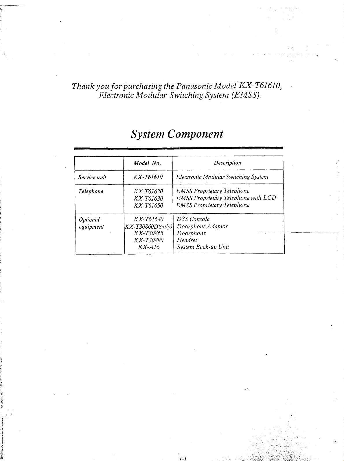
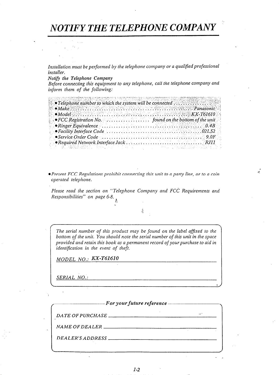
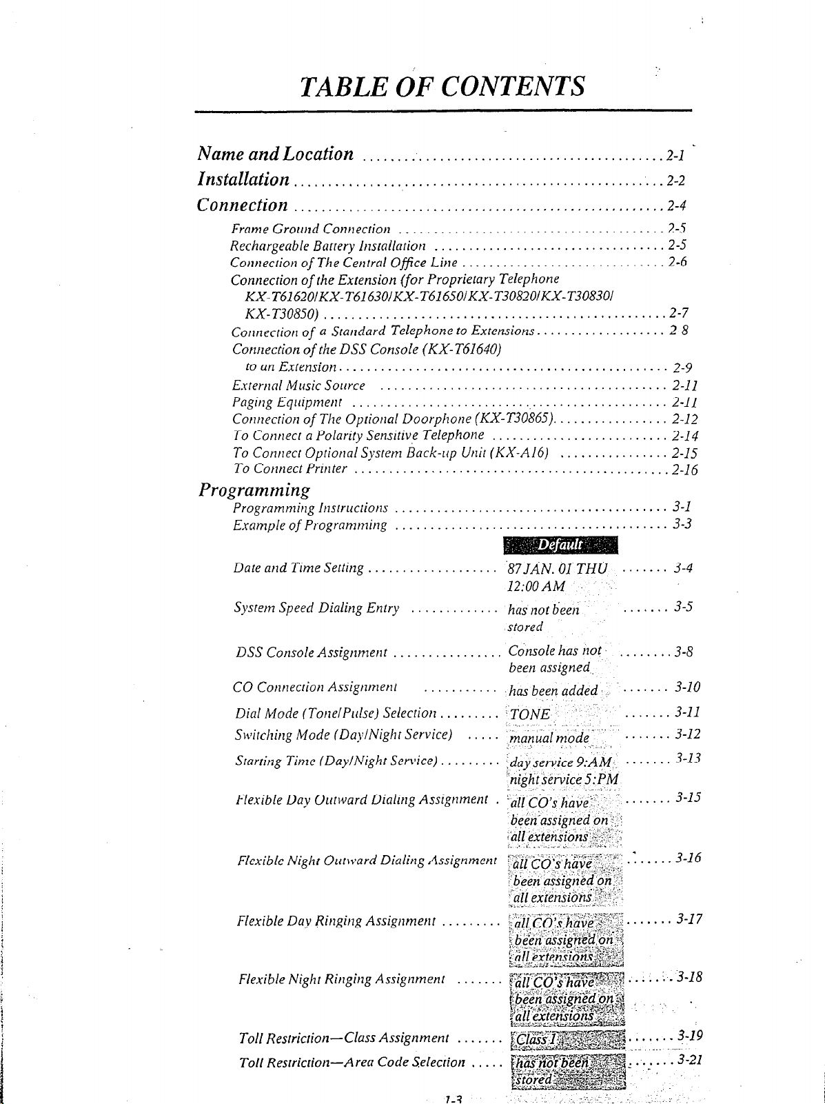
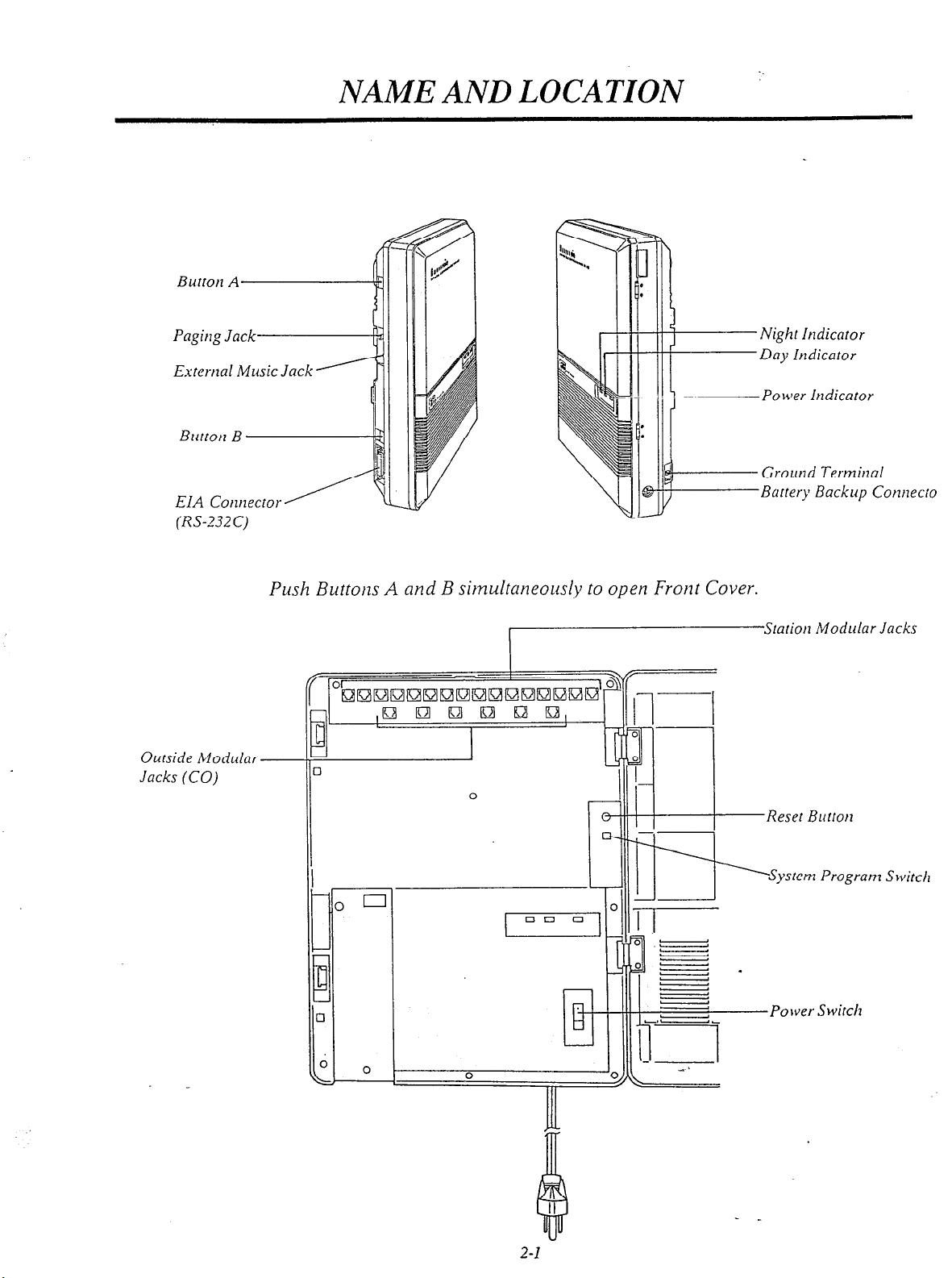
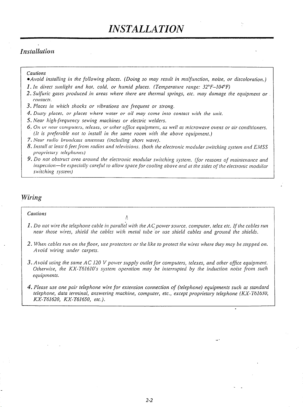
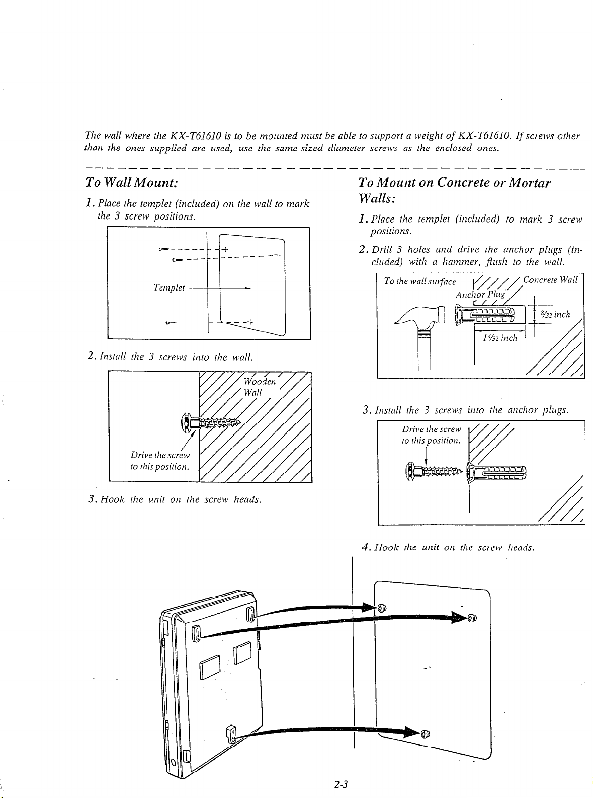
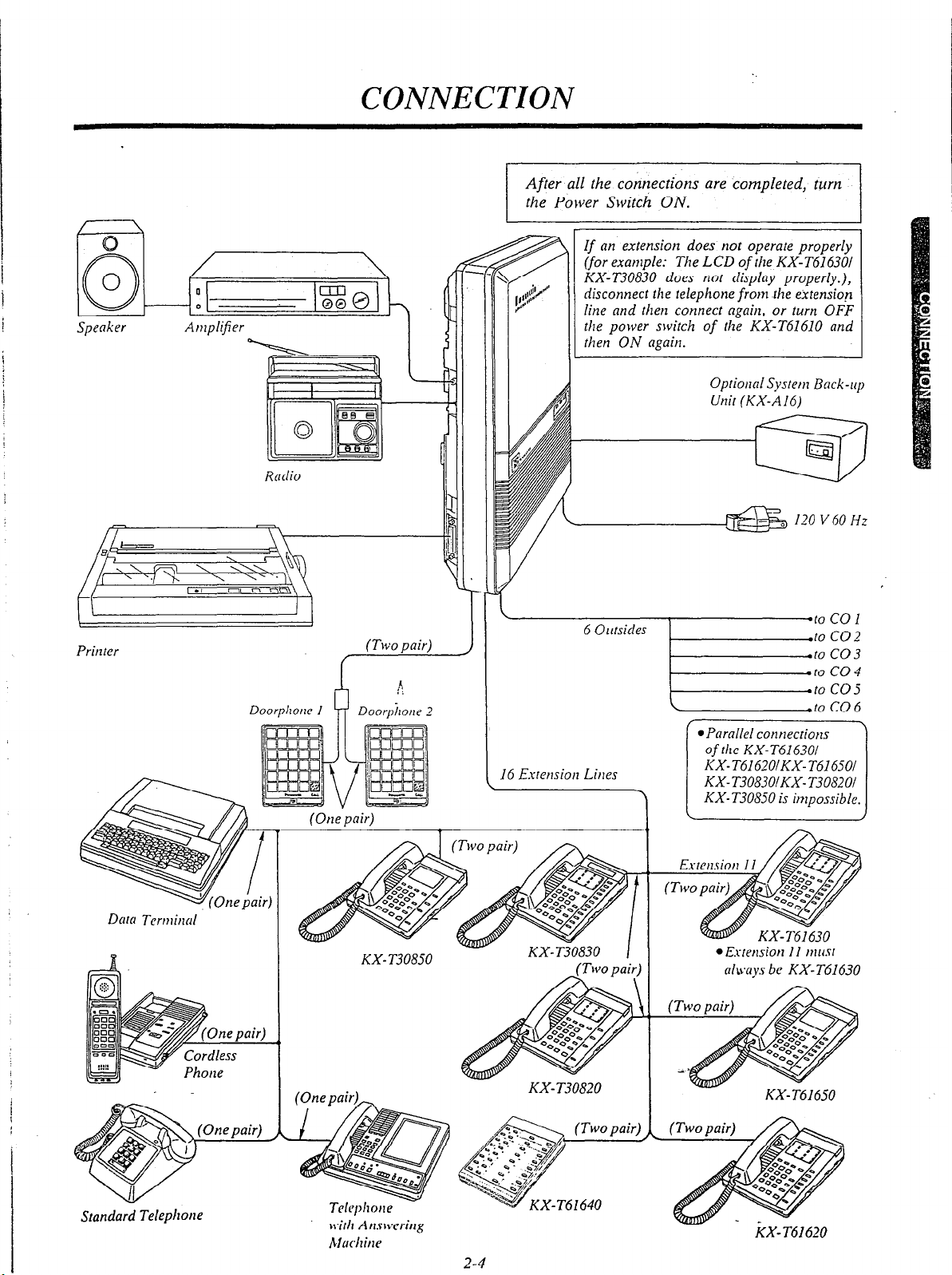
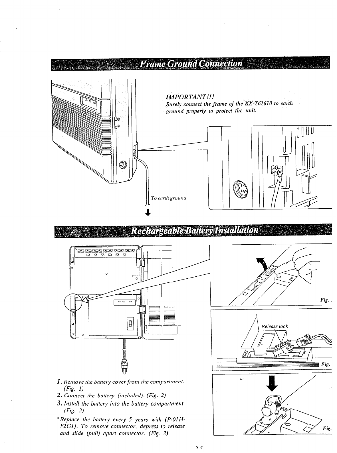
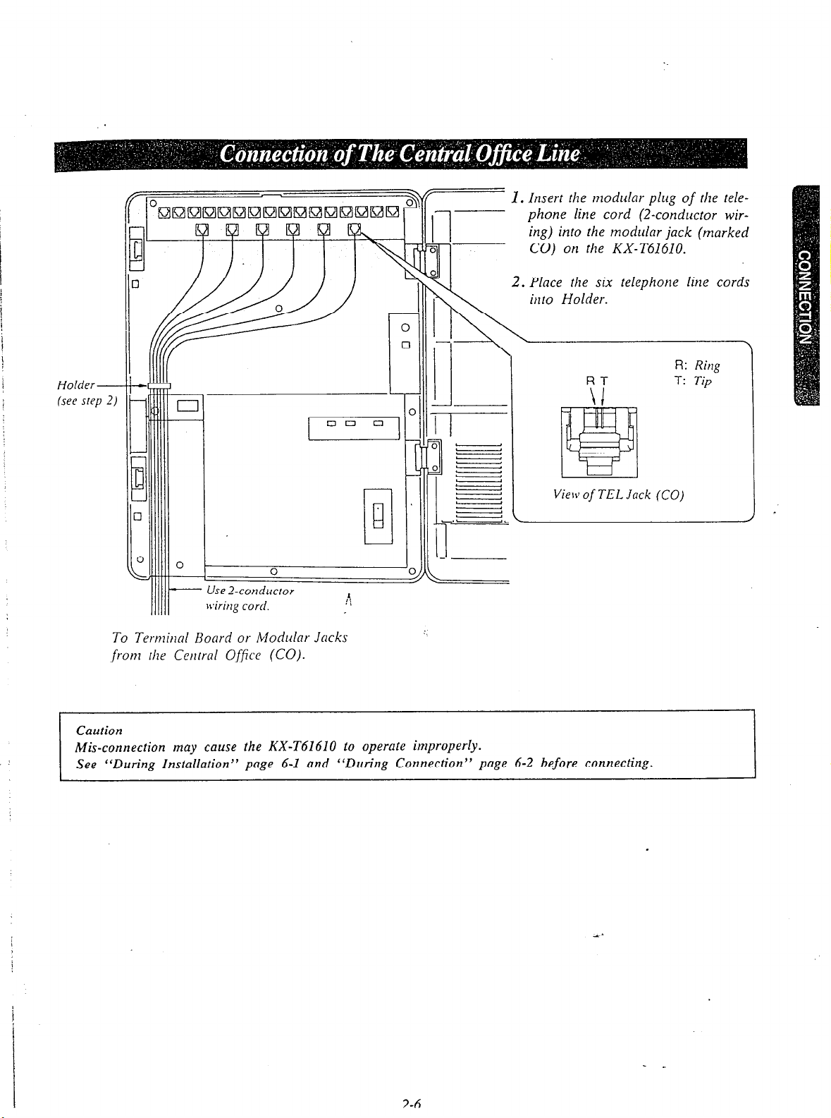
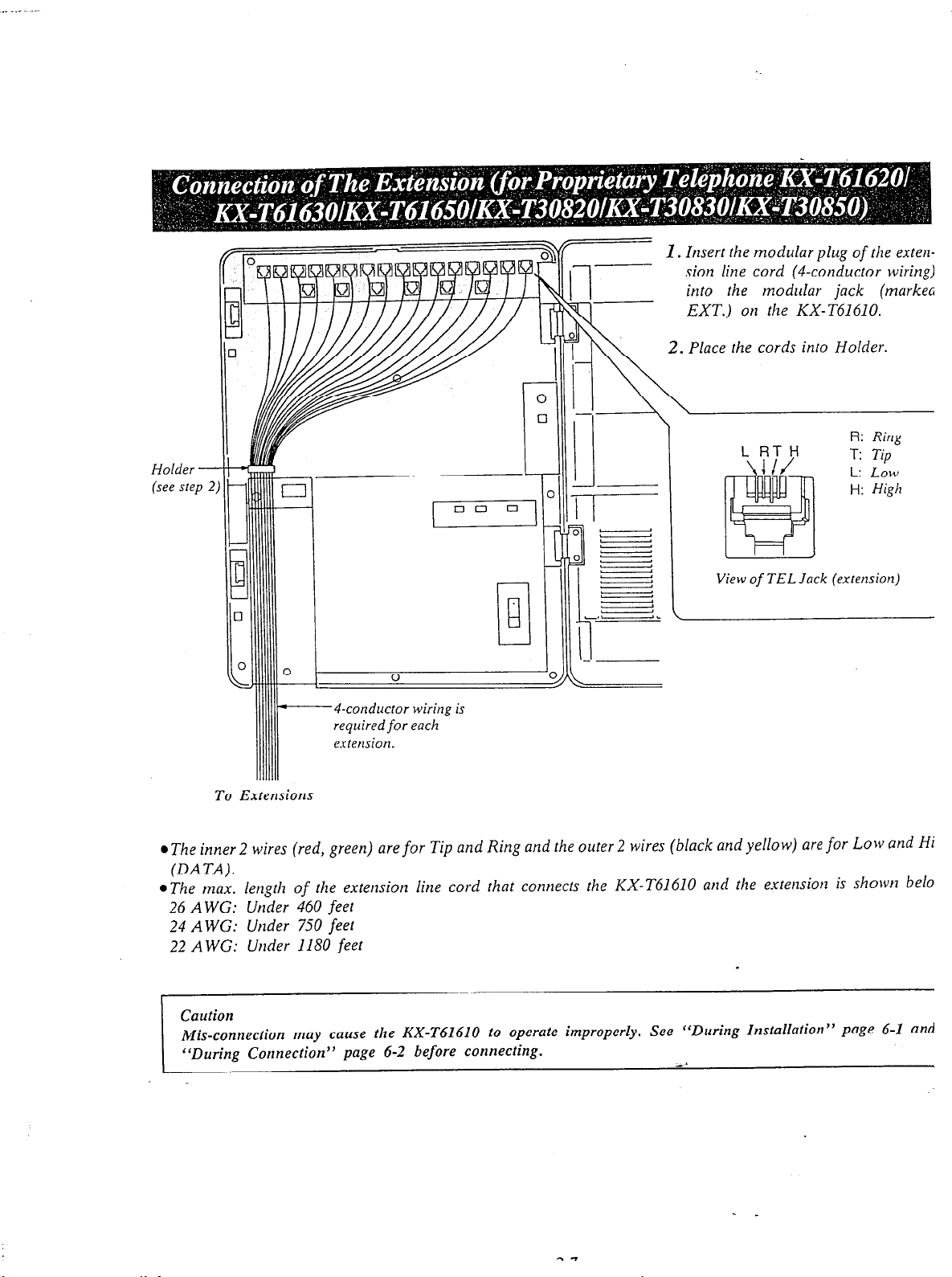
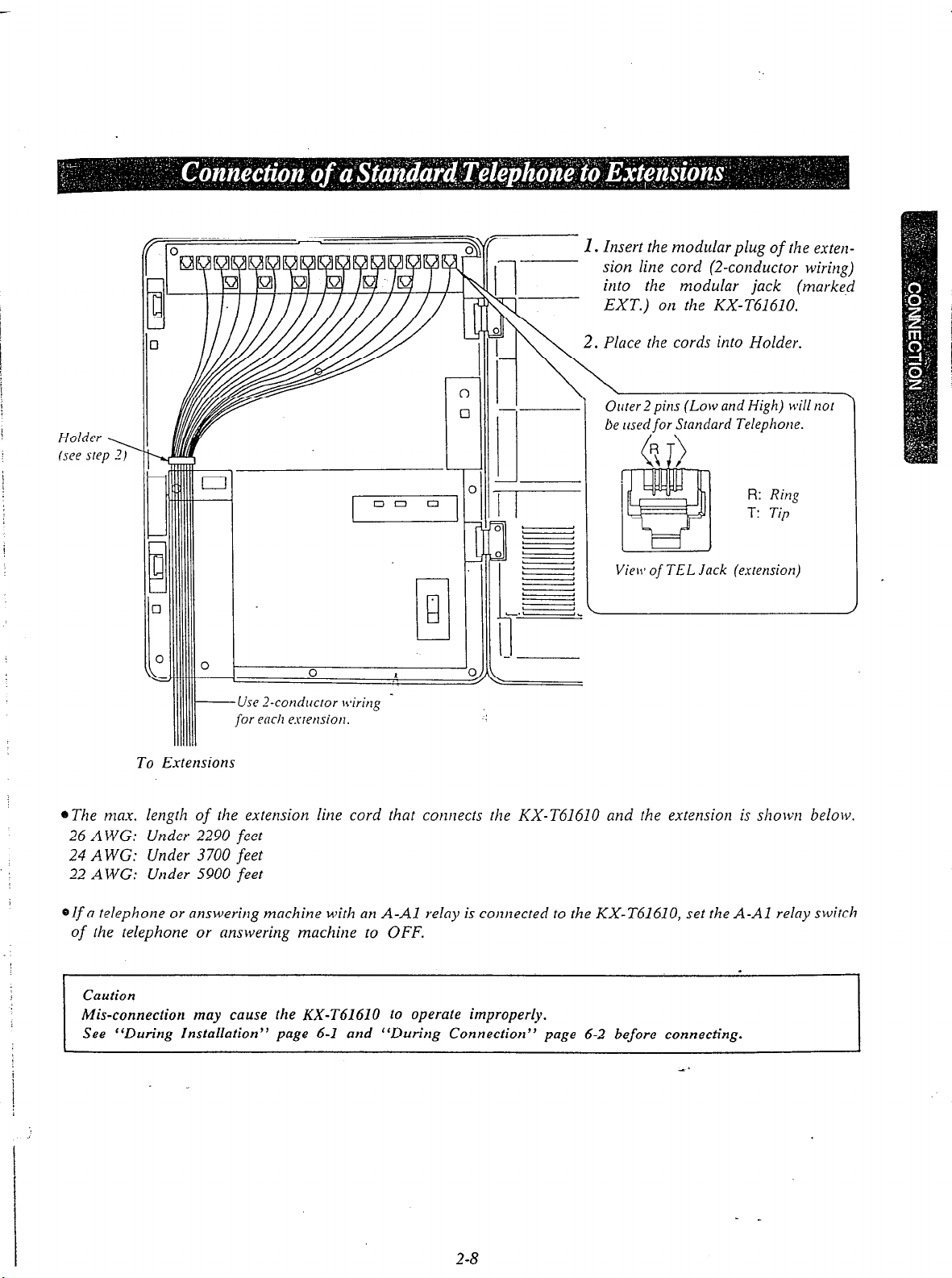
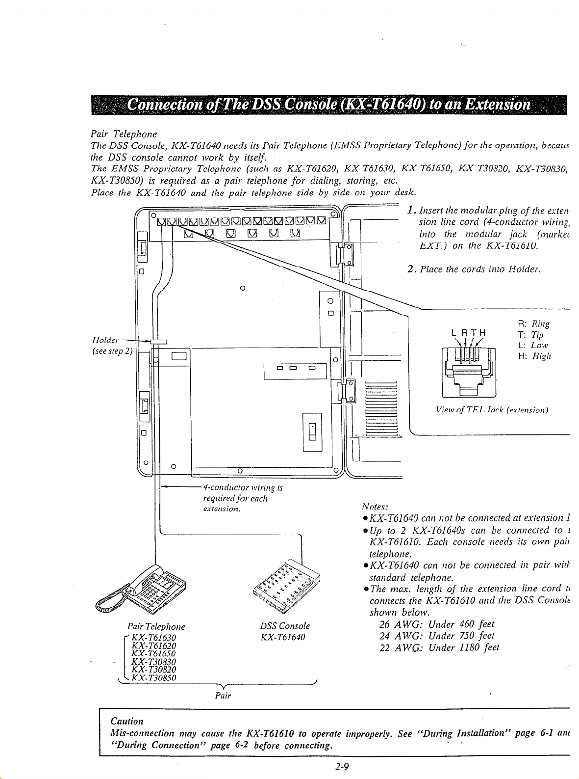
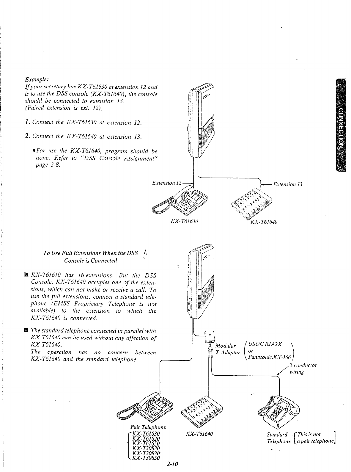
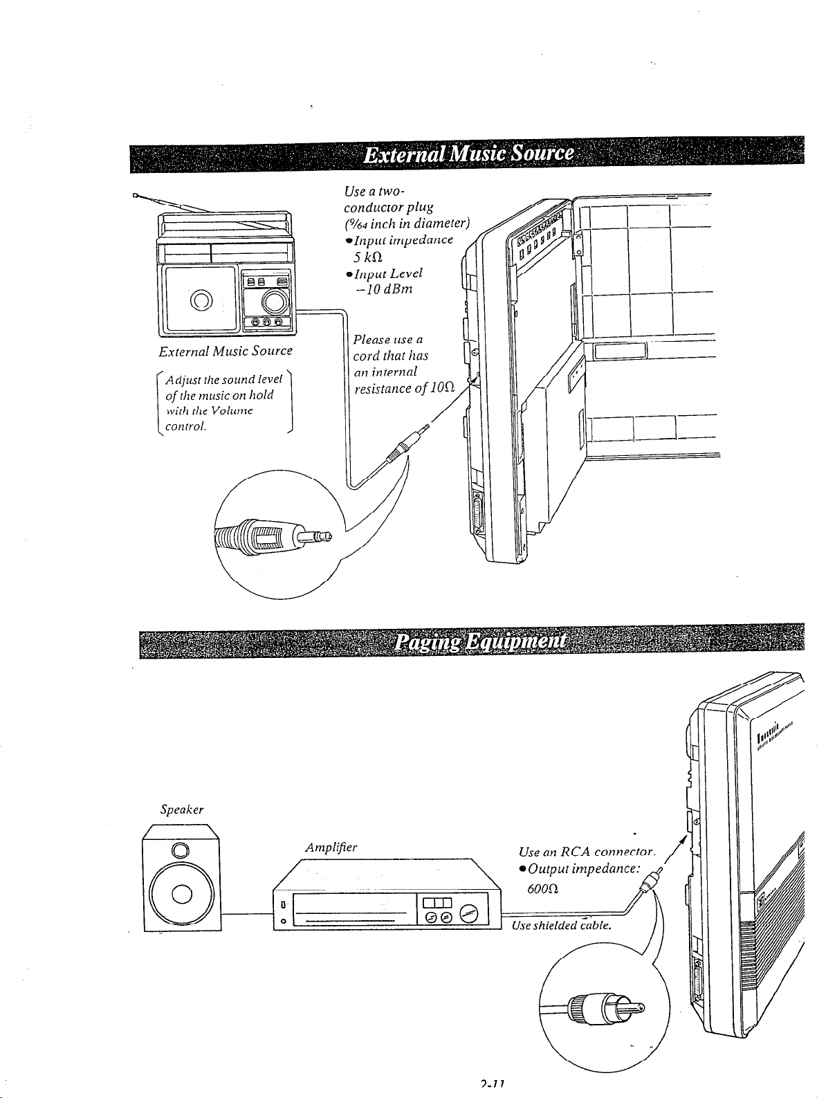
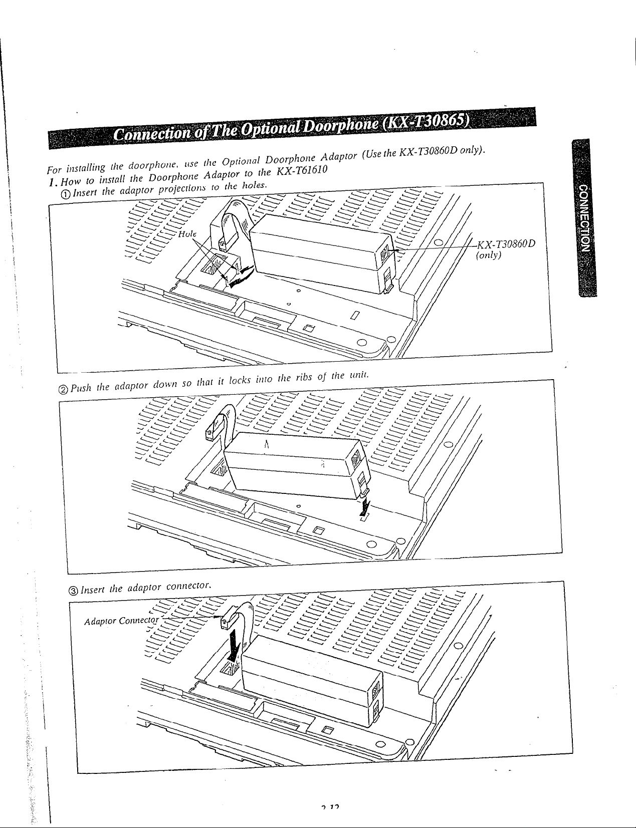
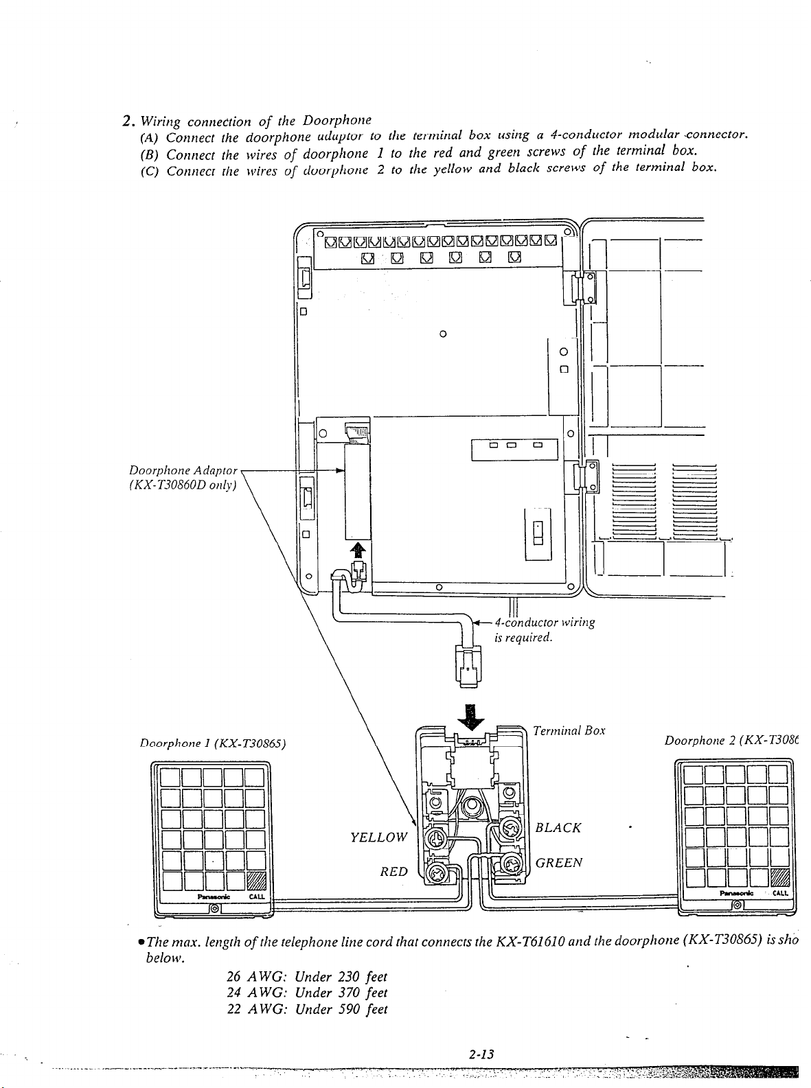
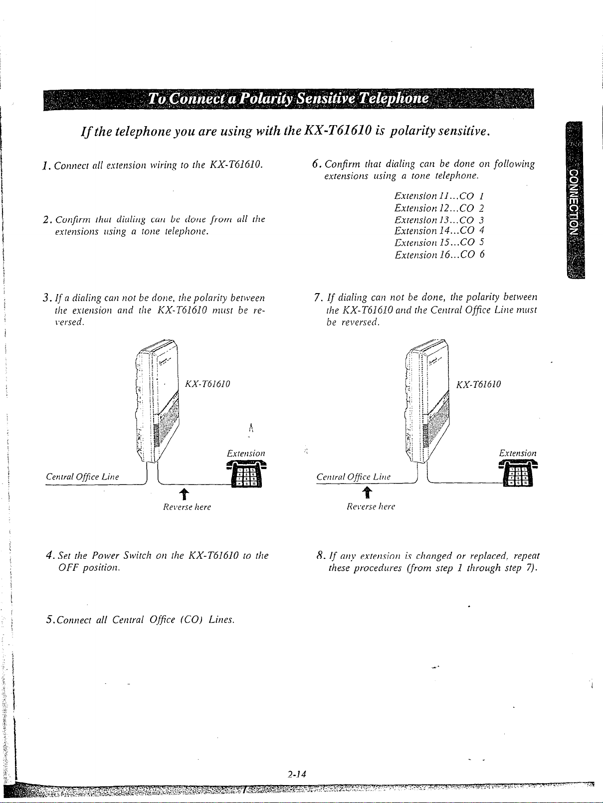
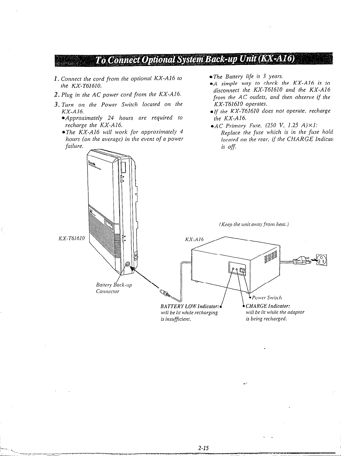
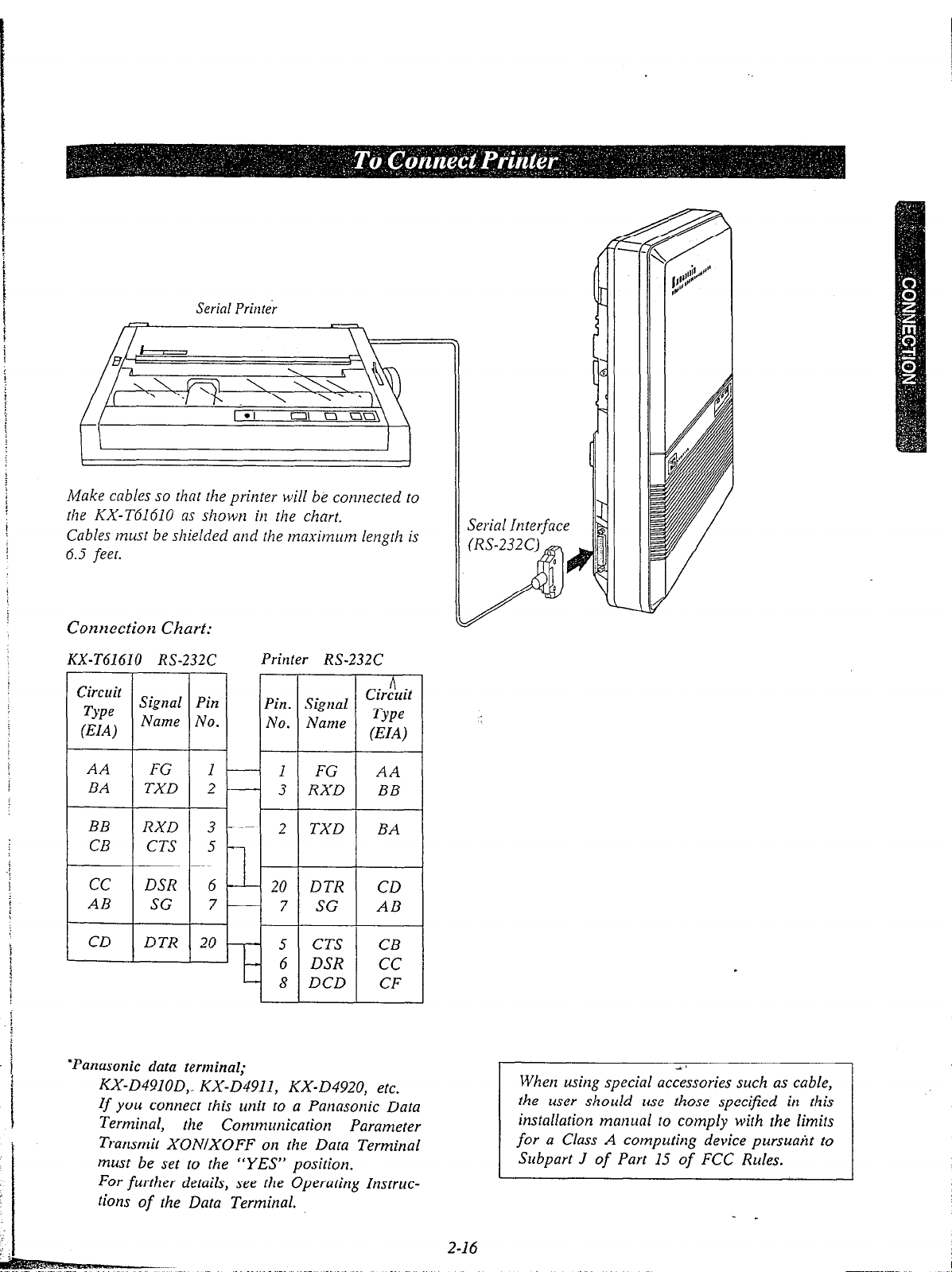
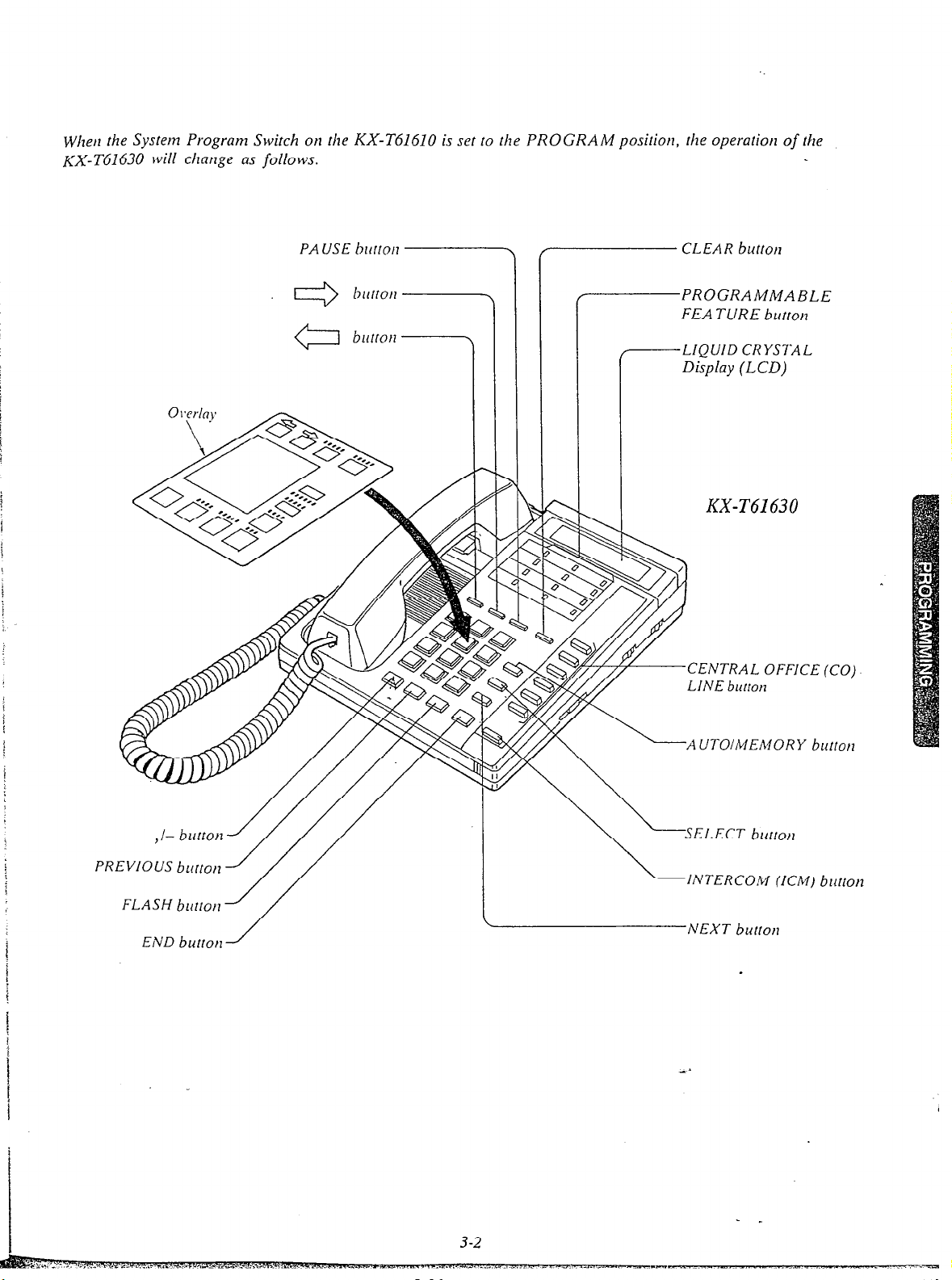
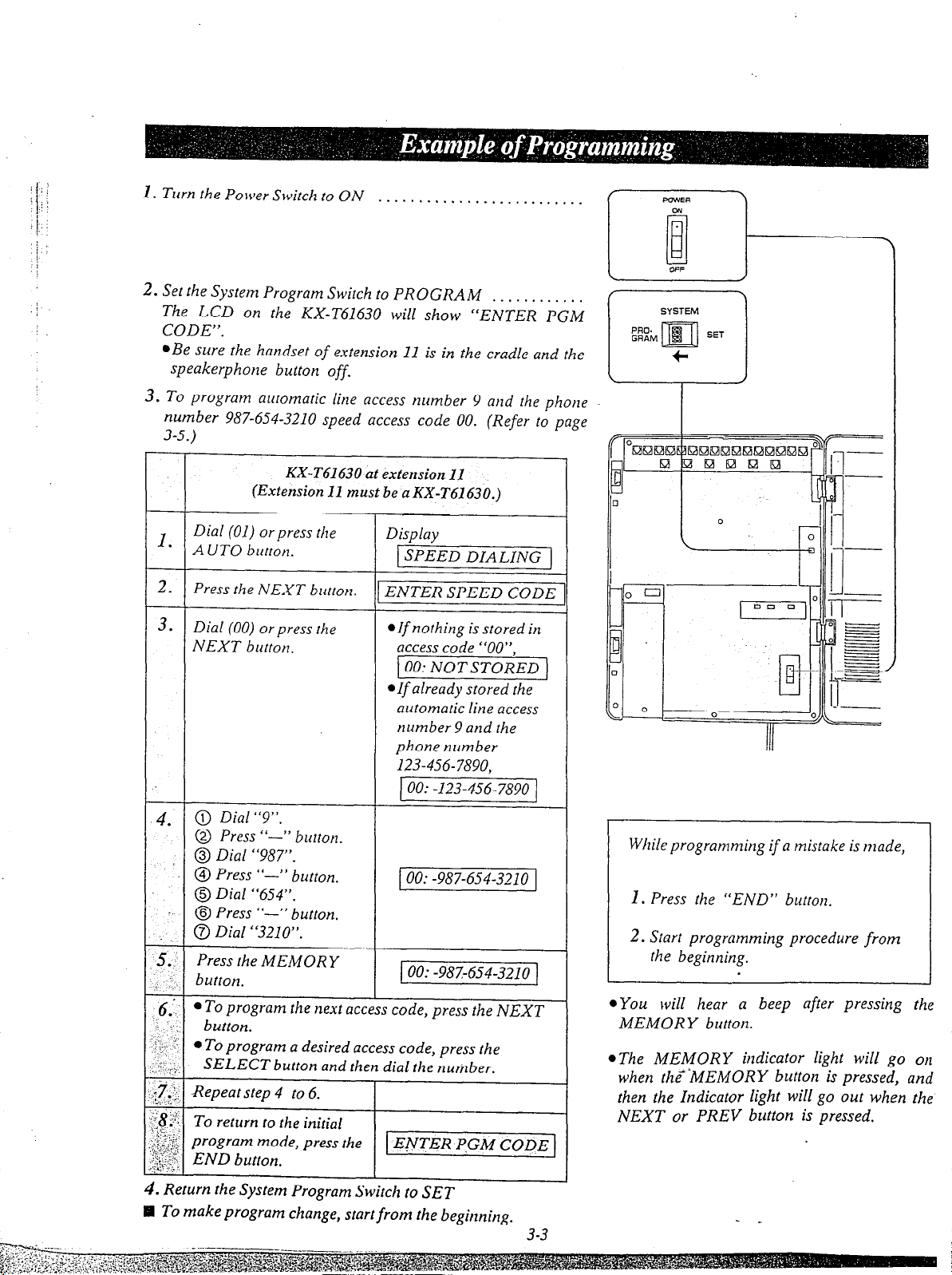

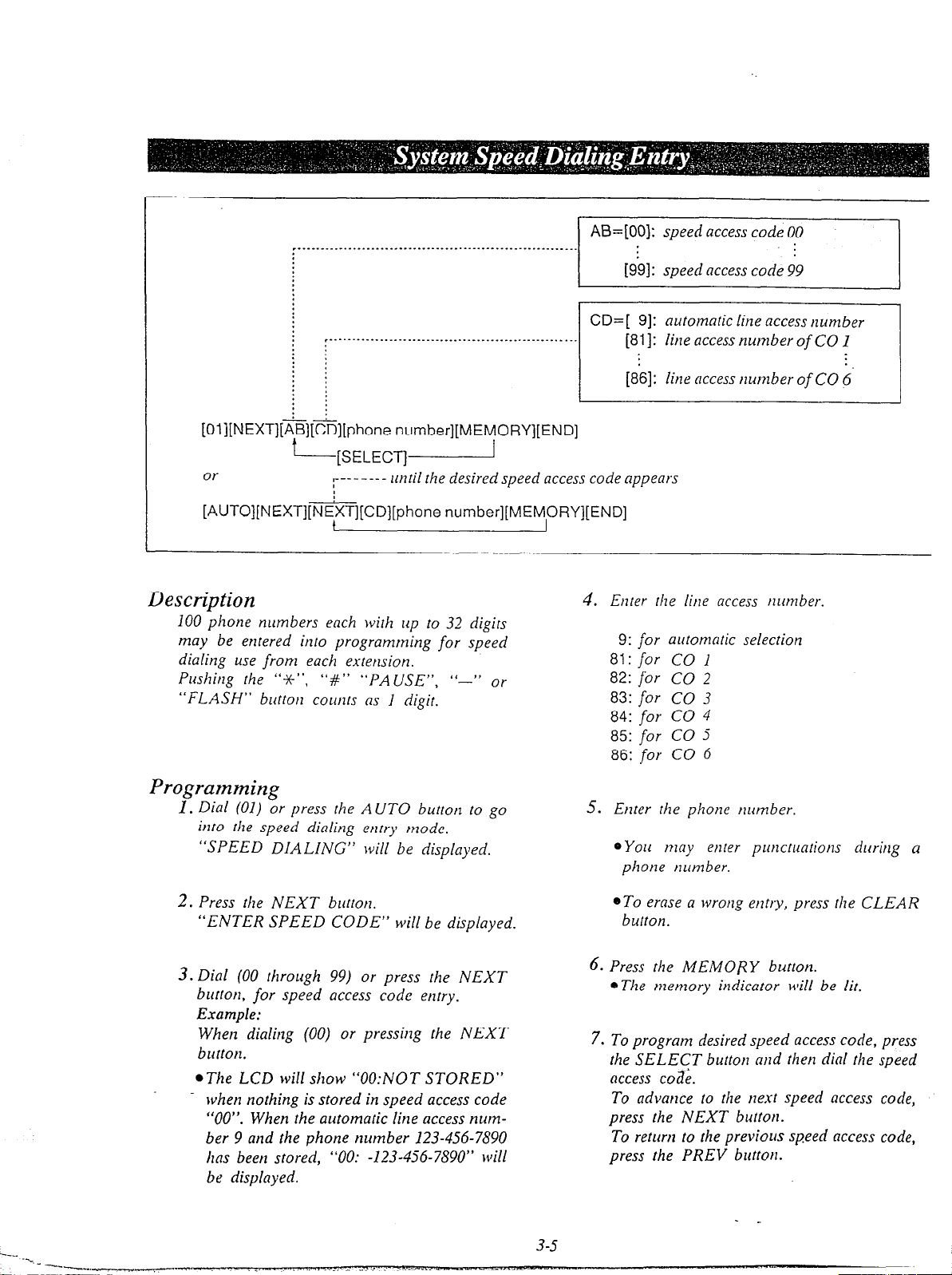
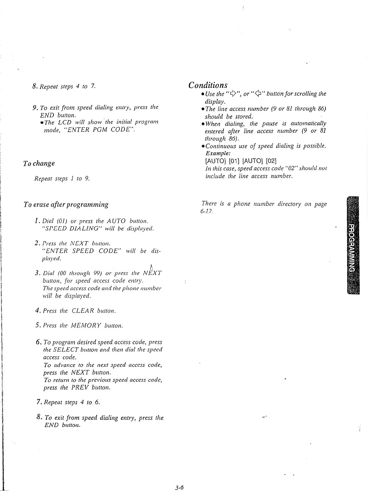
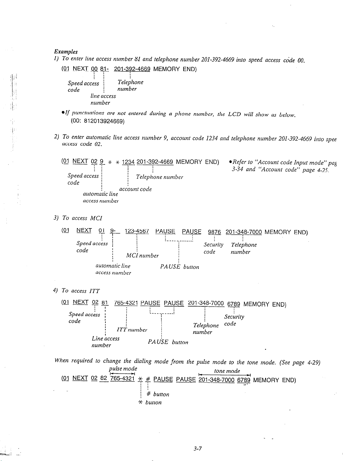


 Loading...