

Page 1
Panasonic
Software Commands Manual
for KX-P7200
Table of Contents
Printing Description
PCL Commands
HP-GL/2 Command
PJL Commands
Appendix A
Appendix B
MSL Symbol List
Index
Character Tables
Unicode Symbol List
Page 2

PCL Commands
Page Formatting
Font Selection
Moving the Printing Position
Raster Graphics
Macros
Print Model
Advanced Graphics
Status Readback
Miscellaneous
HP-GL/2 Commands
The Configuration and Status
The Polygon Group
The Vector Group
The Line and Fill Attributes Group
The Character Group
Page 3

PJL Commands
Introduction
PJL Command Syntax and Format
Print Environment Composition
PJL Reset Conditions
Environment Variables
Status Message
Usage of Command
PJL Commands
Page 4

Printing Description
Introduction
The items discussed in the following sections are listed below:
• Page Orientation, Paper Length, Paper Width
• Printable Area
• Coordinate System
• Fonts
• Terms for Bitmap Font
• Paper Formatting
• Print Start Conditions
Page 5

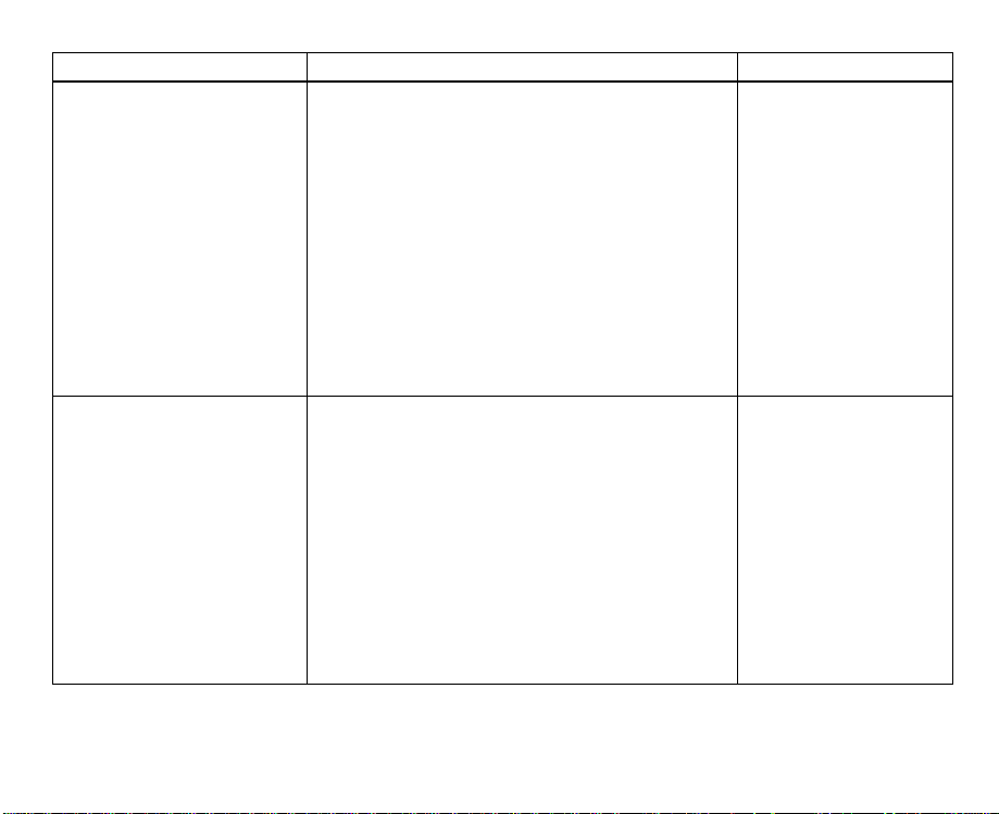
Page Orientation, Paper Length, Paper Width
Only single sheet paper can be used with this printer. The size of the paper is
determined by the paper length and paper width settings. Both paper length and
paper width are decided by the direction of printing, i.e., page orientation.
There are two page orientations: portrait printing mode and landscape printing
mode. In the portrait printing mode, the text is printed perpendicular to the
longer side of the paper. On the other hand, in the landscape printing mode, the
text is printed parallel with the long side of the paper.
The method of paper setting and the paper feed direction are the same in both
modes.
The paper feed direction, paper length, paper width and paper orientation are
shown in Figure 2.1.
Page 6
ABCDEFG
Paper lengthPaper width
Paper
length
Portrait printing mode Landscapeprinting mode
Figure2.1 Portrait and landscape orientation
Paper
width
ABCDEFG
Page 7

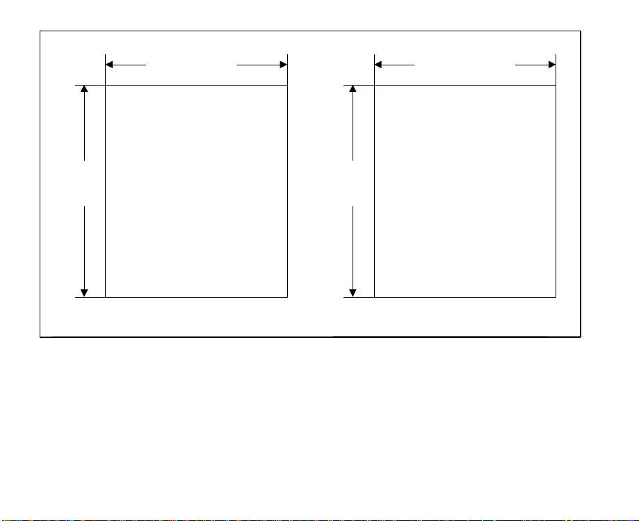
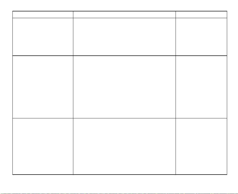
Printable Area
The printable area refers to the area where texts and figures can be printed.
There exists an unprintable area on the margins of the paper where texts and
figures cannot be printed (illustrated below by oblique lines).
The printable area size shown in the table is for the printer with 300 dpi
resolution. Multiply the dots by 2 for the printer with 600 dpi resolution.
For the printer with 600 dpi resolution, 1 dot is equal to 1/
600
".
Page 8
B
C
B
C
A D
Printing area
A D
C
F
C
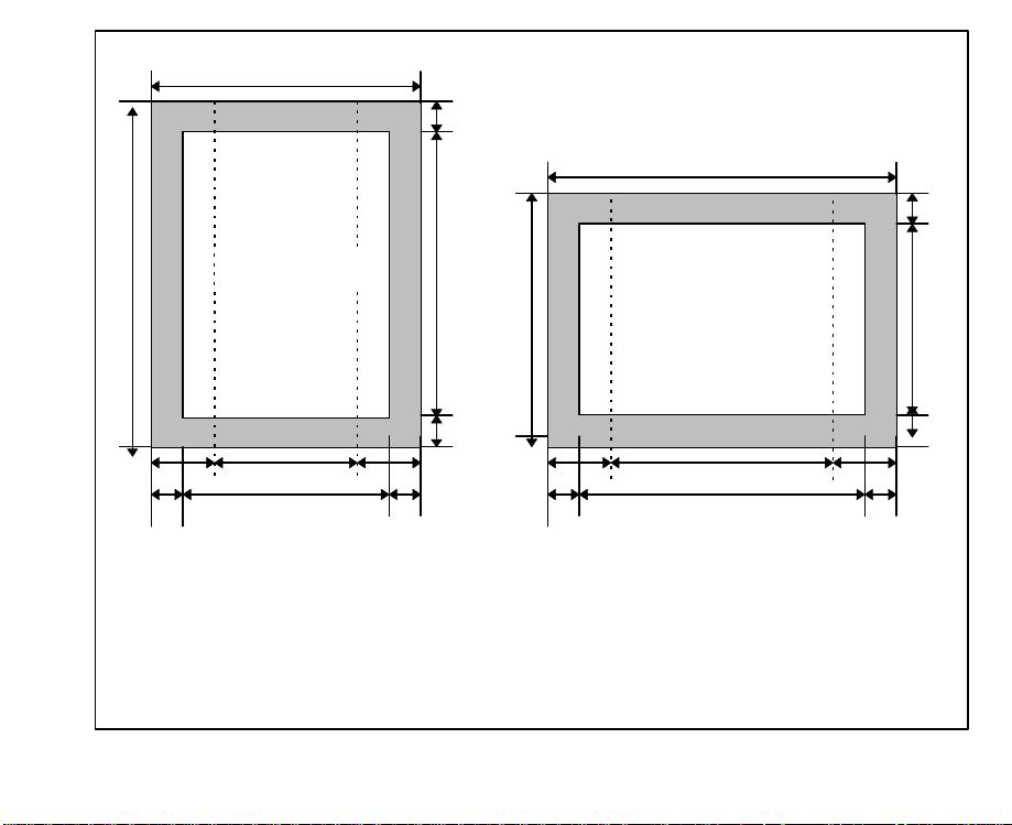
A:
Paper length
B:
Paper width
C:
Distance between the edge of
the paper and the printable area
D:
Length of the printable area
G
E
Portrait Landscape
F
C
F
C
E:
F:
G:
Figure 2.2 printable area and unprintable area
Printing area
G
E
Width of the printable area
Distance between the edge of
the paper and the logical page
Width of the logical page
F
C
C
Page 9
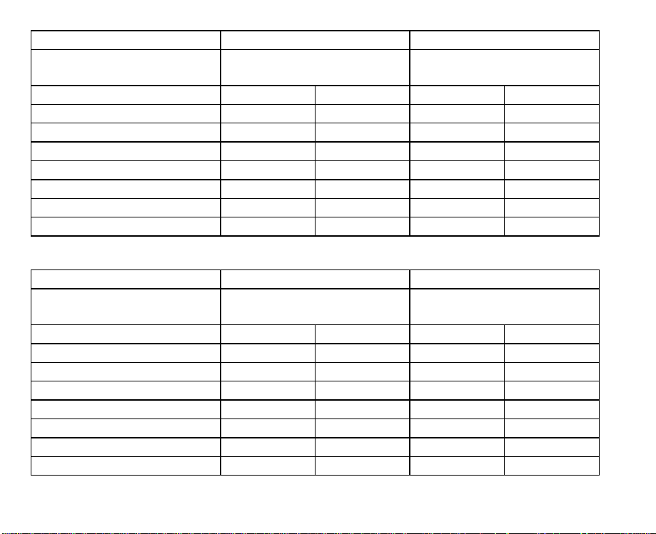
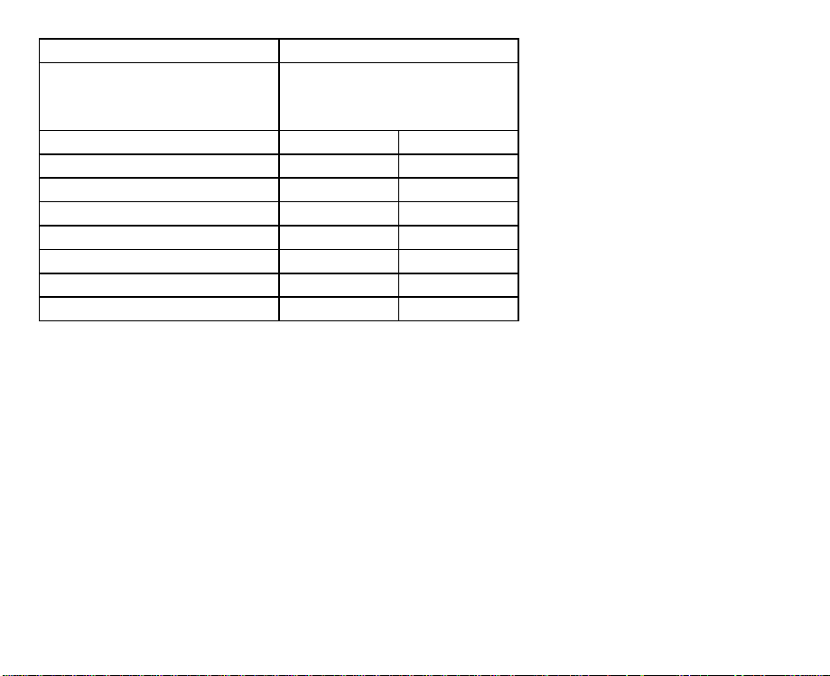
Paper Type Letter Legal
Paper Size 8. 5"x11"
(215.9x279.4 mm)
8. 5"x14"
(215.9x355.6 mm)
Portrait/ Landscape P L P L
A(dots) 3,300 2,550 4,200 2,550
B(dots) 2,550 3,300 2,550 4,200
C(dots) 50 50 50 50
D(dots) 3,200 2,450 4,100 2,450
E(dots) 2,450 3,200 2,450 4,100
F(dots) 75 60 75 60
G(dots) 2,400 3,180 2,400 4,080
Table 2.1 Printable area size (1 dot=1/
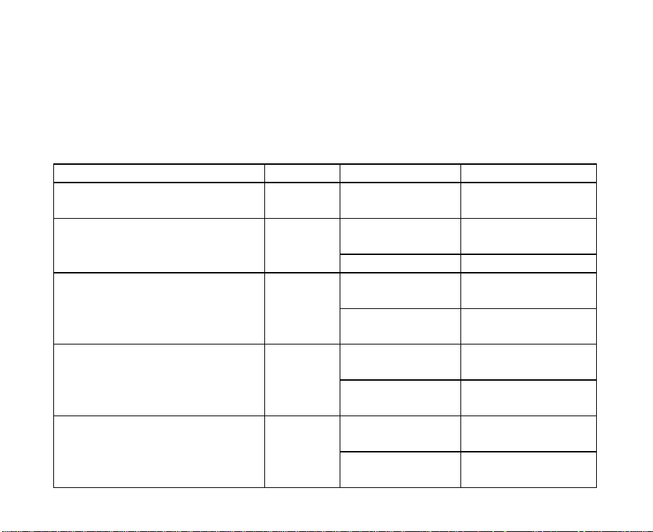
Paper Type A4 EXECUTIVE
Paper Size 210x297 mm
(8.27"x11.7")
7. 25"x10.5"
(184.1x266.7 mm)
Portrait/ Landscape P L P L
A(dots) 3,507 2,480 3,150 2,175
B(dots) 2,480 3,507 2,175 3,150
C(dots) 50 50 50 50
D(dots) 3,407 2,380 3,050 2,075
E(dots) 2,380 3,407 2,075 3,050
F(dots) 71 59 75 60
G(dots) 2,338 3,389 2,025 3,030
Table 2.1 Printable area size (continued) (1 dot=1/
300
300
")
")
Page 10

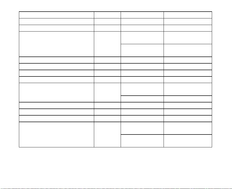
Paper Type Envelope #10 Monarch
Paper Size 4.13"x9.5"
(104.9x241.3 mm)
3. 88"x7.5"
(98.5x190.5 mm)
Portrait/ Landscape P L P L
A(dots) 2,850 1,237 2,250 1,162
B(dots) 1,237 2,850 1,162 2,250
C(dots) 50 50 50 50
D(dots) 2,750 1,137 2,150 1,062
E(dots) 1,137 2,750 1,062 2,150
F(dots) 75 60 75 60
G(dots) 1,087 2,730 1,012 2,130
Table 2.1 Printable area size (1 dot=1/
300
")
Paper Type International
DL
Paper Size 110x220 mm
(4.33"x8.66")
International
C5
162x229 mm
(6.4"x9.02")
Portrait/ Landscape P L P L
A(dots) 2,598 1,299 2,704 1,913
B(dots) 1,299 2,598 1,913 2,704
C(dots) 50 50 50 50
D(dots) 2,498 1,199 2,604 1,813
E(dots) 1,199 2,498 1,813 2,604
F(dots) 71 59 71 59
G(dots) 1,157 2,480 1,771 2,586
Table 2.1 Printable area size (continued) (1 dot=1/
300
")
Page 11
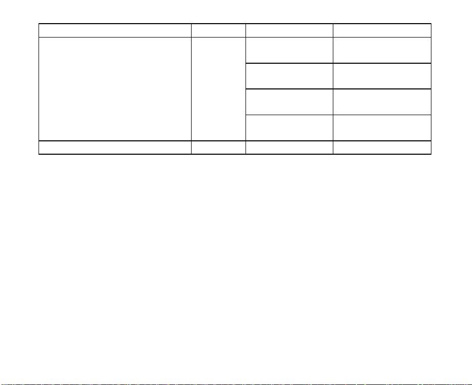
Paper Type Custom
Paper Size maximum
215.9x355.6 mm
(8.5"x14")
Portrait/ Landscape P L
A(dots) 4,200 2,550
B(dots) 2,550 4,200
C(dots) 50 50
D(dots) 4,100 2,450
E(dots) 2,450 4,100
F(dots) 75 60
G(dots) 2,400 4,080
Table 2.1 Printable area size (1 dot=1/
300
")
Page 12

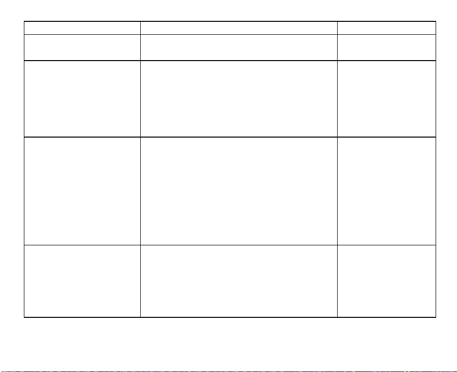
Coordinate System
A coordinate system should be set up as a standard for deciding the location
where texts or figures are printed. The origin of the coordinate system is
initialized at the left upper corner of the paper in accordance with the printing
direction in both portrait printing mode and landscape printing mode.
Refer to Figure 2.3.
Origin (0,0)
Y
Figure 2.3 Origin of the coordinate system
X
ABCDEFG
Portrait printing mode
Orig in (0,0)
X
ABC DEFG
Y
Landscape printing mode
Page 13
Built-in Fonts
The fonts except Line Printer are all scalable fonts. Proportional spacing for a
scalable font can be set from 4 to 999.75 points. The value is increased or
decreased by 0.25. Fixed pitch for a scalable font can be set from 0.44 to 99.99
cpi (characters per inch). The value is increased or decreased by 0.01. Line
Printer is the only supported Bitmap Font (16.66 pitch, 8.5 points).
Font Pitch Style Stroke Weight
Albertus ps Upright
Antique Olive ps
Arial ps
CG Omega
CG Times
Table 2.2 Built-in fonts (continued) ps=proportional spacing
ps
ps
Upright
Italic Medium
Upright
Italic
Upright
Italic
Upright
Italic
Medium
Extra Bold
Medium
Bold
Medium
Bold
Medium
Bold
Medium
Bold
Medium
Bold
Medium
Bold
Medium
Bold
Page 14
Font Pitch Style Stroke Weight
Clarendon Condensed ps Condensed Bold
Coronet ps Italic Medium
Upright
Courier fixed
Italic
Medium
Bold
Medium
Bold
Garamond Antiqua ps Upright Medium
Garamond Halbfett ps Upright Bold
Garamond Kursiv ps Italic Medium
Garamond Kursiv Halbfett ps Italic Bold
Medium
Bold
Letter Gothic fixed
Upright
Italic Medium
Line Printer fixed Upright Medium
Marigold ps Upright Medium
Symbol ps Upright Medium
Medium
Bold
Medium
Bold
Times New Roman
Upright
ps
Italic
Table 2.2 Built-in fonts (continued) ps=proportional spacing
Page 15
Font Pitch Style Stroke Weight
Upright
Italic
Univers
Wingdings ps Upright Medium
Table 2.2 Built-in fonts ps=proportional spacing
ps
Condensed
Condensed
Italic
Medium
Bold
Medium
Bold
Medium
Bold
Medium
Bold
Page 16
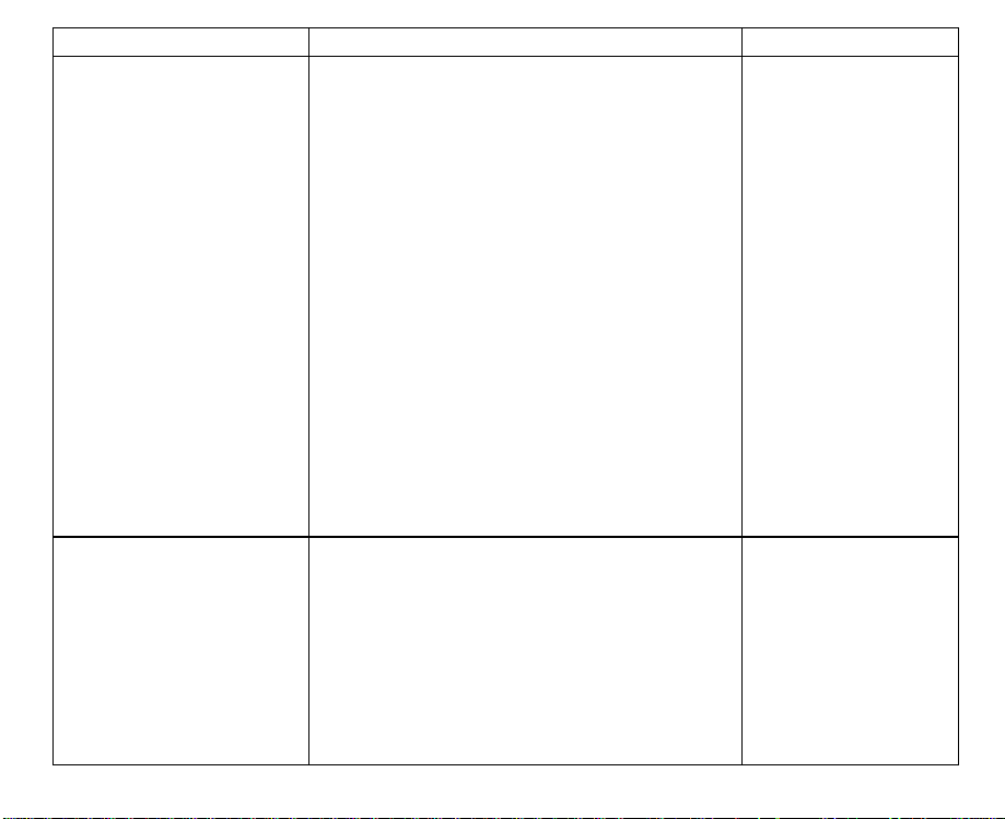
Terms for Bitmap Font
Cel
l
CellCellheigh
t
Cellheigh
t
Cell
The term “cell” refers to the frame of the character which decides the size of
bitmap when designing a font. The horizontal line of dots is called the dot line
and vertical line is called dot column. The bottom line of the cell is called the first
line and the leftmost column is called the first column.
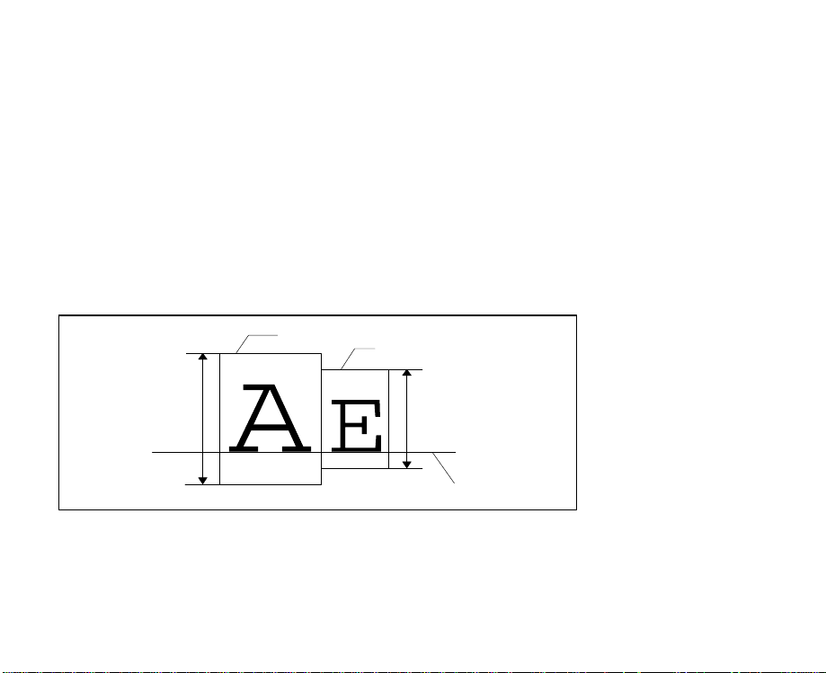
Baseline
The term “baseline” refers to a standard line for printing characters in line. The
position of a baseline is decided when designing a font.
For example, when consecutive characters have different cell heights, they are
printed so that the baseline of each character is aligned.
Figure 2 4 Baseline
Left/Right Offset of a Character
Left offset of character means the number of the dot lines on the left of a
character where no dots are printed, and right offset refers to the number of the
dot lines on the right of a character where no dots are printed.
Page 17

Cell height
Leftoffse
t
e
Cell width
Baselin
Right offset
Figure 2.5 Character cell
Page 18
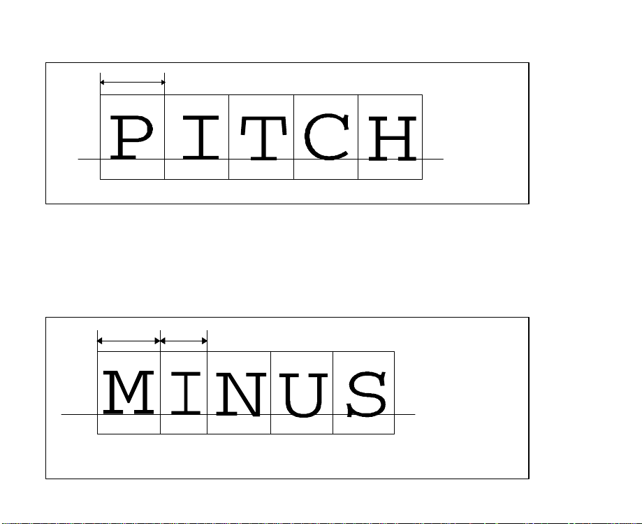
Fixed Pitch Characters
HMI
A
e
B
A
B
≠
The cell width is constant for fixed pitch characters.
Baseline
Figure 2.6 Fixed character pitch
Proportional Spacing Characters
Proportional spacing means the character width of the cell is different for each
character according to the width of each character.
An “M” is a wider character than an “I”.
Baselin
Figure 2.7 Proportional spacing
Page 19

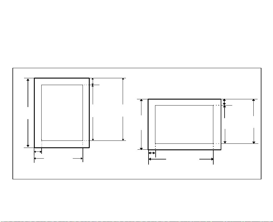
Paper Formatting
The printer has the following paper formatting requirements:
• Page width is the distance from the left edge to the right margin of the paper
and must be less than or equal to the paper width.
• Page length must be greater than or equal to 1 line and less than or equal to
the paper length.
Page 20
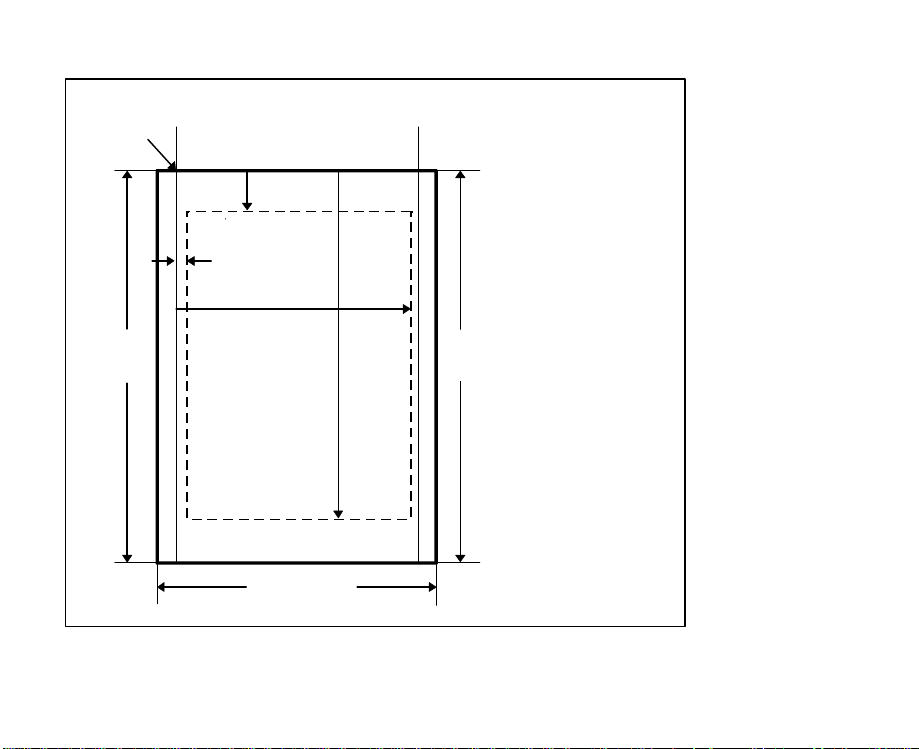
Portrait Printing Mode
Single page
Origin
Page width
TM
LM
Page
length
RM
Page width
Figure 2.8 Paper formatting-portrait
BM
Page
length
TM: Top margin
BM: Bottom margin
LM: Left margin
RM: Right margin
Page 21
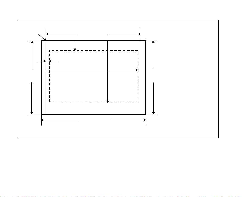
Landscape Printing Mode
Single page
Origin
Page width
TM
BM
Page
length
LM
RM
Paper width
Figure 2.9 Paper formatting-landscape
Page
length
TM: Top margin
BM: Bottom margin
LM: Left margin
RM: Right margin
Page 22

Print Start Conditions
This printer is a page printer. As such it will only begin printing when print start
conditions are satisfied, that is, after the layout of data for one sheet of print has
been completed. Therefore, if the print start conditions are not satisfied, the data
to be printed remains in the printer even if all the printing data has been sent
from the computer.
• FF is received.
• Reset command is received.
• Orientation is changed.
• DATA TIME OUT is set to ON and the time set has passed.
• PRINT key has been pressed.
• Page size or page length is changed.
Page 23
PCL Commands
Command Group Function Name
Page Formatting
Font Selection
Control code comparison chart-page reference table (continued)
Orientation
Page Size
Print Direction
Top Margin
Text Length
Skip Perforation
Left Margin
Right Margin
Margin Clear
Lines Per Inch
VMI
HMI
Shift In
Shift Out
Symbol Set
Spacing
Print Pitch
Character Height
Character Style
Stroke Weight
Typeface
Default Font
ESC “&l#O”
ESC “&l#A”
ESC “&a#P”
ESC “&l#E”
ESC “&l#F”
ESC “&l#L”
ESC “&a#L”
ESC “&a#M”
ESC “9”
ESC “&l#D”
ESC “&l#C”
ESC “&k#H”
SI
SO
ESC “(ID”
ESC “(s#P”
ESC “(s#H”
ESC “&k#S”
ESC “(s#V”
ESC “(s#S”
ESC “(s#B”
ESC “(s#T”
ESC “(#@”
Page 24
Command Group Function Name
Moving the
Printing Position
Raster Graphics
Font Downloading
Control code comparison chart-page reference table (continued)
Horizontal
Vertical
Resolution Set
Graphics Presentation Mode
Height
Width
Graphics Start
Y Offset
Compression Mode
Data Sending
Graphics End Version B
Version C
Font ID define
Font Header
Character Code Define
Download Character
Font Define
Font/character Control
User-Defined Symbol Set ID Code
Define User-Defined Symbol Set
User-Defined Symbol Set Control
ESC “&a#C”
ESC “*p#X”
ESC “&a#H”
ESC “&a#R”
ESC “*p#Y”
ESC “&a#V”
ESC “*t#R”
ESC “*r#F”
ESC “*r#T”
ESC “*r#S”
ESC “*r#A”
ESC “*b#Y”
ESC “*b#M”
ESC “*b#W”
ESC “*rB”
ESC “*rC”
ESC “*c#D”
ESC “)s#W”
ESC “*c#E”
ESC “(s#W”
ESC “(#X”
ESC “*c#F”
ESC “*c#R”
ESC “(f#W”
ESC “*c#S”
Page 25
Command Group Function Name
Macros Macro ID
Macro Control
Print Model Pattern Transparency Mode
Source Transparency Mode
Current Pattern
Designating Graphics Pattern
Logical Operation
Pixel Placement
Advanced
Graphics
Status Readback
Control code comparison chart-page reference table (continued)
Rule Width
Rule Height
Pattern ID
Rule/Pattern Print
Download Pattern Data
Tile Pattern
Control Pattern
Set Status Readback Location Type
Set Status Readback Location Unit
Inquire Status Readback Entity
Free Space
Flush All Pages
Echo
ESC “&f#Y”
ESC “&f#X”
ESC “*v#O”
ESC “*v#N”
ESC “*v#T”
ESC “*c#G”
ESC “*l#O”
ESC “*l#R”
ESC “*c#A”
ESC “*c#H”
ESC “*c#B”
ESC “*c#V”
ESC “*c#G”
ESC “*c#P”
ESC “*c#W”
ESC “*p#R”
ESC “*c#Q”
ESC “*s#T”
ESC “*s#U”
ESC “*s#I”
ESC “*s1M”
ESC “&r#F”
ESC “*s#X”
Page 26
Command Group Function Name
Miscellaneous
Plotting Picture
Frame
Control code comparison chart-page reference table
Display Function
Transparent Print
Underlining Setting
Release
Push/Pop Printing Position
Half Line Feed
CR/LF/FF Action
Wrap Around
Number of Copies
Paper Input Control
Duplex Page Side Selection
Simplex/Duplex Print
Printer Reset
Self-test
Left Offset Registration
Top Offset Registration
Universal Exit/Start of PCL
Decide PCL Units
Picture frame Horizontal
size-Decipoints
Picture frame Vertical
size-Decipoints
Set picture frame anchor point
GL Plot Horizontal size-Inches
GL Plot Vertical size-Inches
Enter PCL Mode
Enter GL Mode
ESC “Y”
ESC “Z”
ESC “&p#X”
ESC “&d#D”
ESC “&d@”
ESC “&f#S”
ESC “=”
ESC “&k#G”
ESC “&s#C”
ESC “&l#X”
ESC “&l#H”
ESC “&a#G”
ESC “&l#S”
ESC “E”
ESC “z”
ESC “&l#U”
ESC “&l#Z”
ESC “%-12345X”
ESC “&u#D”
ESC “*c#X”
ESC “*c#Y”
ESC “*c#T”
ESC “*c#K”
ESC “*c#L”
ESC “%#A”
ESC “%#B”
Page 27
PCL Commands
Page Formatting
Page formatting is executed by setting the following: orientation, page size,
page length, top margin, text length, skip perforation, vertical line feed,
horizontal spacing, left margin and right margin. Format can be classified by
orientation in two ways; portrait printing mode and landscape printing mode.
Top margin
Page
length
Left margin
Rightmargin
Portrait printing mode
Figure 3.1 Page formatting
Text
length
Bottom
margin
Page
length
Left ma rgin
Right margin
Landscape printing mode
Top margin
Text
length
Bottom
margin
Page 28

Orientation
Setting:
This command decides the page orientation. When the orientation is changed,
top margin, text length, left margin, right margin, HMI and VMI return to the
default setting and the primary and secondary fonts are changed and reevaluated. Therefore, this command should be sent from the computer as the
first command of the page.
When data already exists in the printer and the printer receives this command,
printing automatically starts and the printing position is moved to the first column
of the first line.
ESC “&l#O”
#=0: Portrait printing mode
1: Landscape printing mode
2: Reverse portrait printing mode
3: Reverse landscape printing mode
Page 29

Page Size
Setting:
This command sets the page size and also sets page length, page width, top
margin, bottom margin, left margin and right margin to default setting values.
ESC “&l#A”
#= 1: Executive (71/4x101/2 inch)
3: Legal (81/2x14 inch)
2: Letter (81/2x11 inch)
6: Ledger (11x17 inch)
26: A4 (210x297 mm)
27: A3 (297x420 mm)
80:
Monarch (Letter37/8x71/2 inch)
81:
Commercial #10 (Business41/8x91/2 inch)
90: International DL (110x220 mm)
91: International C5 (162x229 mm)
101: Custom (maximum 13x19 inch)
Print Direction
Setting:
ESC “&a#P”
#=
0 0°
90 90°
180 180°
270 270°
Portrait
Landscape
Reverse prtrait
Reverse landscape
This command rotates the logical page coordinate system in the current
orientation without outputting a page. You are able to print in four orientations on
the same page. This command rotates the coordinate system in 90 degrees
increments counterclockwise.
Page 30

Top Margin
Setting:
This command sets the top margin. The top margin indicates the margin on the
upper end of the printing paper.
The desired length of the margin is entered by the number of the lines(1 line =
VMI) in the value field #, and any value from 0 to the page length can be used.
The default setting is ½ inch from top of logical page.
When the top margin is set, the text length returns to the default setting.
Since an unprintable area of 60 dots exists on the upper end of the printing
paper, some upper part of text cannot be printed when the top margin is set as 0
or 1 line.
This command only sets the top margin. It does not move the printing position to
the top margin. Therefore, the printing position must be moved to the top margin
by the vertical movement of the printing position command when printing from
the top margin is required. Otherwise the printing from the top margin is effective
only on the next page. When VMI is 0, this command is invalid.
ESC “&l#E”
#=Number of lines
Page 31

Text Length, Bottom Margin
Setting:
This command sets the text length. Text length refers to the number of lines to
be printed on the paper.
Enter the desired number of lines in the value field #. When # exceeds the value
of “Page Length-Top Margin”, this command is invalid.
When the text length is set, the bottom margin (the margin on the lower end of
paper) can be automatically determined by the following formula:
Bottom Margin == Page Length −− Top Margin −− Text Length
The text length returns to the default setting in the following cases:
• When the page size is changed
• When the orientation is changed
• When the page length is set
• When the top margin is set
ESC “&l#F”
#=Number of lines
Page 32

Skip Perforation
Setting:
Release:
The bottom margin is controlled by the skip perforation mode command.
When the skip perforation is set, as soon as the printing position enters the
bottom margin area, the paper feed is performed and the printing starts from the
top margin of the next page. When the skip perforation is released, the printing
continues even after the printing position enters the bottom margin area. When
the printing position exceeds the page length, the paper feed is executed and
printing starts from the top of the next page. In this case, any characters in the
unprintable area cannot be printed.
The default setting of the bottom margin is 1/2". Therefore, the default setting of
the text length is; Page Length −−Top Margin −− 1/2".
ESC “&l1L”
ESC “&l0L”
Left Margin
Setting:
ESC “&a#L”
#=Column number
Release:
This command defines the left margin. Enter the desired number of columns
from the origin in the value field # to set the left margin. One column is equal to
one HMI.
ESC “9” is used to clear the left and right margins at the same time.
ESC “9”
Page 33

Right Margin
Setting:
ESC “&a#M”
#=Column number
Release:
This command defines the right margin. Enter the desired number of columns
from the origin in the value field # to set the right margin. One column is equal to
one HMI. Default setting of the left margin is column 0 and the right margin is
the page width.
ESC “9” is used to clear the left and right margins at the same time.
ESC “9”
Vertical Motion Amount
Vertical motion amount is the amount of the line feed, and is a unit of one line of
page length, top margin, text length and vertical movement of printing position.
Vertical motion amount is set by either of the following two methods:
Page 34

• By the number of lines per inch
Setting:
ESC “&l#D”
#= 1: 1 lpi
2: 2 lpi
3: 3 lpi
4: 4 lpi
6: 6 lpi
8: 8 lpi
12: 12 lpi
16: 16 lpi
24: 24 lpi
48: 48 lpi
Enter a desired number of lines per inch. 1, 2, 3, 4, 6, 8, 12, 16, 24 and 48 are
acceptable values as the value field #.
For example, to print 6 lines per inch, the computer must send ESC “&l6D”.
• By VMI (Vertical Motion Index)
VMI sets the vertical motion amount in multiples of 1/48 inch.
Setting:
ESC “&l#C”
#= Multiples of 1/48 inch
Enter a desired number for VMI from 0 to 32767 in the value field #.
This value field can be specified to four decimal places. For example, when VMI
= 8, the vertical motion amount is 8 x 1/48"= 1/6", thus 6 lines are printed per inch.
The default setting of the vertical motion amount is 1/6", or 8 as VMI.
Page 35

Horizontal Motion Amount
Horizontal motion amount is the amount of horizontal space between characters
and is a unit of the left and right margins in the fixed pitch mode. This overrides
the print pitch set by the font selection. This is set by HMI (Horizontal Motion
Index). HMI sets the horizontal motion amount in multiples of 1/
120
inch.
Setting:
ESC “&k#H”
#= Multiples of 1/
120
inch
Enter a desired number of HMI from 0 to 32767 in the value field #. This value
field can be specified to four decimal places.
For example, when HMI is 12, the horizontal motion amount is 12 x 1/
"= 1/10",
120
thus 10 characters are printed per inch.
The default setting of HMI is the width of the SP (20
) code of the font which is
HEX
selected at present.
The HMI returns to the default setting in the following cases:
• When the orientation is changed
• When the symbol set of the font which is valid at present is changed
• When the print pitch of the font which is valid at present is changed
• When the spacing of the font which is valid at present is changed
• When the point size of the font which is valid at present is changed
• When the primary font and the secondary font are changed
In the proportional space (PS) mode, the HMI is valid only on SP code.
Page 36

Font Selection
Commands that set font characteristic enable font selection of internal or
download fonts, and fonts from external font cards.
The printer has seven font characteristics as follows:
Symbol Set: the set of characters available for printing.
Spacing: is either fixed or proportional. Fixed spaced characters all
have the same width; proportional character widths vary from
character to character. In proportional spacing, an “M” takes
up more space than an “I”.
Pitch: is the number of characters printed per inch in a font with
fixed spacing. Because proportional widths vary, pitch is not
applicable to proportional fonts.
Point Size: describes the vertical size of a character. One inch is equal
to 72 points.
Style: can be either upright or italic.
Stroke Weight: describes the “heaviness” of the font.
Type Face: refers to the design of the character set.
After checking the font characteristics and giving them a priority, the printer
selects the font in the printer that most closely matches the font described by the
font selection commands. The default characteristics are those of default fonts.
Page 37

Primary/Secondary Font Attribute
Font characteristics are set on both primary and secondary fonts, therefore two
fonts can be selected.
Only one of these attributes can be given to a font.
The primary font attribute is given to the font that is used most often in the
document, while the secondary attribute is given to an auxiliary font.
These fonts can be alternated by using the control codes SI and SO. The
commands to select fonts assign each font characteristic to these attributes; as
a result they give these attributes to the fonts.
SI (Shift In): This command assigns the font to be printed after this
command as the primary font until SO is received (primary
select mode).
SO (Shift Out): This command assigns the font to be printed after this
command as the secondary font until SI is received
(secondary select mode).
Detailed explanations of how each font characteristic is set are as follows:
Symbol Set
Setting/Primary:
Setting/Secondary:
This command selects a symbol set.
Enter a symbol set ID number in the ID field of the above command.
ESC “(ID”
ESC “)ID”
Page 38

Symbol Set ID
ISO 60 Norwegian V1
ISO 4 United Kingdom
Windows 3.1 Latin 2
ISO 69 French
ISO 21 German
ISO 15 Italian
Microsoft Publishing
DeskTop
PS Text
MC Text
Ventura International
Ventura US
Wingdings
PS Math
Ventura Math
Math-8
Symbol
ISO 8859/1 Latin 1 (ECMA-94)
ISO 8859/2 Latin 2
ISO 8859/9 Latin 5
ISO 11 Swedish
ISO 17 Spanish
Windows 3.1 Latin 5
PC-Turkish
Table 3.2 Symbol set ID numbers(continued)
0D
1E
9E
1F
1G
0I
6J
7J
10J
12J
13J
14J
579L
5M
6M
8M
19M
0N
2N
5N
0S
2S
5T
9T
Page 39

Symbol Set ID
ISO 6 ASCII
Legal
Roman-8
Windows 3.0 Latin 1
PC-8
PC-8 Danish/Norwegian
PC-850 Multilingual
Pi Font
PC-852 Latin 2
Windows 3.1 Latin 1
Table 3.2 Symbol set ID numbers
Spacing
Setting/Primary:
Setting/Secondary:
This command selects fixed pitch or proportional spacing.
ESC “(s#P”
ESC “)s#P”
#=0: Fixed spacing
1: Proportional spacing
0U
1U
8U
9U
10U
11U
12U
15U
17U
19U
Page 40

Print Pitch
• Case 1
Setting/Primary:
Setting/Secondary:
This command sets the print pitch by entering the pitch (number of characters
per inch) in the value field #. If proportional spacing is set, this setting is
registered as a characteristic, but is invalid.
• Case 2
Setting:
This command sets the print pitch for both the primary and secondary fonts.
HMI and the print pitch are also changed by this command, but the print pitch of
the font is not affected. Only the spacing amount is changed.
ESC “&k#S”
#=0: 10 cpi
ESC“(s#H”
ESC “)s#H”
#=Number of characters per inch
2: 16.66 cpi
4: 12 cpi
Character Height
Setting/Primary:
Setting/Secondary:
ESC “(s#V”
ESC “)s#V”
#=Height of the font cell in points (1 point is 1/72").
This command sets the character height.
VMI is not affected by setting the point size.
Page 41

Character Style
Setting/Primary:
Setting/Secondary:
Value (#) Character Style
0
1
4
5
8
24
32
64
128
160
Table 3.3 Character style value
This command sets character style listed in Table 3.3.
ESC “(s#S”
ESC “)s#S”
#=Character style value
Upright, Solid
Italic
Condensed
Condensed Italic
Compressed, or Extra Condensed
Expanded
Outline
Inline
Shadowed
Outline Shadowed
Page 42

Stroke Weight
Setting/Primary:
Setting/Secondary:
Value (#) Typeface
-7
-6
-5
-4
-3
-2
-1
0
1
2
3
4
5
6
7
Table 3.4 Typeface value
This command selects the thickness of the characters.
ESC “(s#B”
ESC “)s#B”
#=Thickness value
Ultra Thin
Extra Thin
Thin
Extra Light
Light
Demi Light
Semi Light
Medium, Book, or Text
Semi Bold
Demi Bold
Bold
Extra Bold
Black
Extra Black
Ultra Black
Page 43

Typeface
Setting/Primary:
Setting/Secondary:
This command selects the design of characters.
ESC “(s#T”
ESC “)s#T”
#=Typeface value
Typeface Family
Value (#)
4096
4099
4101
4102
4113
4116
4140
4148
4168
4197
4297
4314
4362
4398
4613
6826
Table 3.5 Typeface value
Typeface Base
Value (#)
0
3
5
6
17
20
44
52
72
101
201
218
266
302
517
2730
Typeface
Line Printer
Courier
CG Times
Letter Gothic
CG Omega
Coronet
Clarendon
Univers
Antique Olive
Garamond
Marigold
Arial
Albertus
Symbol
Times New Roman
Wingdings
Page 44

Typeface Selection
Command
Two-Byte Two-Byte Typeface selected.
Two-Byte One-Byte
One-Byte Two-Byte Typeface* selected.
One-Byte One-Byte Typeface selected.
Table 3.6 One-Byte/Two-Byte typeface selection compatibility
*If you can have two fonts in the printer which have the same value in the lower
(LSB) byte of the font descriptor typeface field, the selected typeface will be one
of these selected at random.
Printer Font
One-Byte/Two-Byte
Typeface Descriptor
Your Printer
Typeface for font
selection is ignored.
Page 45

Default Font Selection
The default font command sets the font to default value.
• To make the primary font default.
Setting:
Any value except 3 is invalid
• To make the secondary font default.
Setting:
Any value except 3 is invalid
ESC “(#@”
#=3: To select all characteristics of the default font as
characteristics of the primary font.
ESC “)#@”
#=3: To select all characteristics of the default font as
characteristics of the secondary font.
Page 46

Moving the Printing Position
The printing position can be moved horizontally or vertically by commands that
change the location of printing data.
Two methods of moving the print position are available; relative movement from
the current printing position and absolute movement from the origin. When the
value in the value field # is prefixed with “+”, the printing position moves relative
to the right in horizontal movement mode and downward in vertical movement
mode. When the value is prefixed with “-” , the printing position moves relative
to the left in horizontal movement mode and upward in vertical movement mode.
When neither “+” or “−” is prefixed, the printing position moves by the designated
distance from the origin.
Three kinds of units for moving the printing position in both horizontal and
vertical directions are available; columns/lines, decipoints (1/
") and PCL Units.
720
Page 47

Horizontal Movement
• By columns
Setting:
ESC “&a#C”
#=Number of columns
This command moves the current printing position to a new column position.
The width of a column depends on the current HMI.
• By decipoints
Setting:
ESC “&a#H”
#=Number of decipoints ( 1/
720
inch)
This command moves the current printing position to a new decipoint position.
• • By PCL units
Setting:
ESC “*p#X”
#=Number of PCL units
This command moves the current printing position to a new PCL units position.
See “Deciding PCL Units”.
Page 48

Vertical Movement
• • By lines
Setting:
ESC “&a#R”
#=Number of lines
This command moves the current printing position to the same position on a new
line.
The height of a line depends on the current VMI.
• By decipoints
Setting:
ESC “&a#V”
#=Number of decipoints ( 1/
720
inch)
This command moves the current printing position to a new decipoint position.
• By PCL units
Setting:
ESC “*p#Y”
#=Number of PCL units
This command moves the current printing position to a new PCL units position.
See “Deciding PCL Units”.
Page 49

Raster Graphics
Raster Graphics is a printing function that prints graphic patterns by sending dot
image data by raster units (scanning line) from the computer.
Raster graphics are printed by using the following procedures:
Setting the Resolution
Setting:
This command sets the dot resolution at 75, 100, 150, 200, 300 or 600 dpi. The
default setting is 75 dpi.
Once raster graphics printing is started, this command is invalid until printing
ends. It is necessary to set the command before starting to print.
The details of the resolution are explained below.
The size of 1 bit of the raster image data actually printed is;
That is, the size at 600, 150, 100 or 75 dpi is , 4, 9 or 16 times as large as that at
300 dpi. Therefore, when the same raster image data is printed in different
resolutions, each dot is printed larger or smaller depending on the selected
resolution. The printed image pattern appears larger and rougher at 75 dpi, and
smaller and finer at 600 dpi as shown in Figure 3.5.
1
/
"x1/
600
1
/
"x1/
300
1
/
"x1/
200
2
/
"x2/
300
3
/
"x3/
300
4
/
"x4/
300
ESC “*t#R”
#=Resolution (75, 100, 150, 200, 300 or 600)
" at 600 dpi
600
" at 300 dpi
300
" at 200 dpi
200
" at 150 dpi
300
" at 100 dpi
300
" at 75 dpi
300
Page 50

Raster Graphics Presentation Mode
Setting:
This command sets the orientation for raster image on the logical page.
The default is 3.
ESC “*r#F”
#=0: To print raster image in orientation of logical page
#=3: To print raster image along the width of physical page
Raster Height
Setting:
This command sets the height in raster rows of the raster areas denoted when the
start raster graphics mode command (ESC “*r#A”) being executed.
The height is the direction perpendicular to that of the arranged raster rows. The
value field # is 0 to logical page length (Y-position of the cursor position).
ESC “*r#T”
#=Height in raster rows
E : Width of
logical page
A :Height of
logicalpage
A=B
Portrait mode 0 & 3
B:Raster
he igh t
C:H eight of
logicalpage
Figure 3.2 Maximum raster height
C=D
D:Rasterheight
Landscape mode 0
F:Raster height
E=F
Landscape mode 3
Page 51

Raster Width
Setting:
This command sets the width in pixels of the raster areas denoted when the start
raster graphics mode command (ESC “*r#A”) being executed.
The width is the same direction as the raster rows are positioned. The value field
# is 0 to logical page width (left graphics margin).
A:Widthof
A=B
ESC “*r#S”
#=Width in pixels of the specified resolution
logical page
B: Raster
width
C=D
C: Widthof
logicalpage
D:R aster width
E:
Height of
logicalpage
F: Raster width
Portrait mode 0 & 3
Landscapemode 0
Figure 3.3 Maximum raster height
E=F
Landscape mode 3
Page 52

Start the Raster Graphics Mode
Setting:
This command directs the printer to start raster graphics printing as well as
deciding the starting point of the graphic to be printed. When the value field # is
0, printing starts vertically from the left end of the printing area, while printing
starts from the current printing position when the # is 1.
When # is 1, the printing position must be moved to the upper left position of the
graphics pattern before entering this command.
ESC “*r#A”
#=0 or 1
Raster Y Offset
Setting:
This command moves the raster line by the set number from the current raster
position in the Y-position of the cursor position.
This command is valid only in the raster graphics mode and within the raster
area.
ESC “*b#Y”
#=Number of raster line of vertical movement (0 to 32767)
Page 53

Set Compression Mode
Setting:
Any value except 0, 1, 2, 3 and 5 is invalid.
This command encodes the raster data by one of four compressed formats:
Run-length encoding, Tagged imaged file format (TIFF) rev. 4.0, Delta row
compression and Adaptive compression.
• Unencoded
This code sends data in the form of binary, without compressing data. One bit
indicates a single dot. Bit 7 of the first byte indicates the first dot of the raster
row. Bit 0 indicates the eighth dot.
• Run-length encoding
This format receives raster data in pairs of bytes. The first byte indicates the
number of repeated data in the second byte.
The number is 0:the pattern of data byte is printed once.
The number is 1:the pattern of data byte is printed twice.
ESC “*b#M”
#=0: Unencoded
1: Run-length encoding
2: Tagged imaged file format (TIFF) rev. 4.0
3: Delta row compression
5: Adaptive compression
The range of number is from 0 to 255.
[(Repetition count byte 1-256)(Pattern byte)].[.][]
Page 54

• Tagged Image File Format Encoding
This format has features of Unencoded and Run-length encoding.
A control byte in the raster data determines whether the subsequent data is
unencoded or encoded. If you send unencoded data, send subsequently bytes of
literal data. If you send encoded data, send subsequently literal patterns and the
number of repetitions.
When the control byte value is negative (-1 to -127), the printer repeats the
subsequent data byte the times of the absolute value.
When a control byte is -7, the raster pattern in the next data byte are repeatedly
printed 8 times.
[Control byte (-1 to -127)](Pattern byte)
When the control byte value is positive (1 to 127) including 0, the printer does
not repeat the data byte. The positive value plus one indicates the number of
unencoded data.
When a control byte is 5, the following 6 bytes are literal raster data bytes.
[Control byte (0 to 127)](Pattern byte)(Pattern byte)...
When a control byte is set to -128, the printer ignores -128 and the subsequent
byte becomes a new control byte.
Note:
We recommend encoding two subsequent identical bytes for a repeated byte, or
encoding the whole codes as literal bytes when literal bytes follow or procede
the two identical bytes.
Page 55

• Delta Row Compression
When a part of bytes in a row are different from those of the preceding row, this
format identifies the difference and sends only the data which is different (the
delta data).
When you encode the row completely different from its preceding row, you must
send the whole data for the row as the delta.
When only one bit in a row is different, you need to send only one byte. The
printer picks up the current row (we call it seed row) to construct the raster data
rows (image) and changes (part of) raster image to make the new row. The
printer uses the subsequent delta compression data to make another one.
A command byte and the replacement bytes are the components of a delta
compression row.
[(Command byte)(1 to 8 Replacement bytes)]
The command bytes indicate:
how many replacement (delta) bytes are followed.
where byte string (the left offset) is replaced.
The replacement bytes indicate:
How many bytes (up to eight bytes) are used to make the new row from the seed
row.
When you need more than eight replacement bytes, you must add command
byte and replacement bytes as follows.
[(Command byte)(1 to 8 Replacement bytes)][(Command byte)(1 to 8
Replacement bytes)]
Page 56

Example: Indicates 2 bytes
Delta row Command byte
compression
mode
SC “*b3m2W”(00000000)2(01111111)
2
Number of bytes to
replace Replacement byte
Relative offset
The upper three bits: shows the number of replacement bytes
(1 to 8 bytes)
The lower five bits: shows the location for the replacement bytes. When a
row has more than one replacement, the second offset
begins at the next untreated byte in the row.
An offset value varies from 0 to 31.
Offsets larger than 31 bytes are available:
Offset value 0 to 30:
The printer offsets replacement bytes from the first byte to the thirty-first byte.
Offset value 31:
Page 57

An offset byte is added to the command byte.
If 255 is set for additional offset bytes, offset bytes must be added until the
required offset value is entered.
If the offset byte is set to less than 255, the printer interprets that the last offset
value and the offset bytes are added.
Example: Replacement byte
ESC “*b3m4W”(00011111)2(11111111)2(00000001)2(11010001)
2
Replace 1 byte Final offset byte
Relative offset; 31
Additional byte offset;255
The three offset values are summed up to 287 by the total of (31+255+1).
For more efficient compression encoding
The seed row is overridden by every raster graphic transfer, regardless of the
compression mode.
The delta compression mode can be used with other modes thanks to the
feature mentioned on the previous page.
When the Raster Graphic Data Sending command, ESC “*b#W”, is set to #=0,
the printer repeats or copies the previous raster row.
When the Raster Y Offset command, ESC “*b#Y”, is set to #=1, the printer sets
the seed row to the row of zero.
A seed row of zero becomes the next delta row.
Page 58

• Adaptive Compression
This code can be used with the other modes (#=0, 1, 2 and 3).
Example:
ESC “*b5m16W”03(h)00(h)0a(h)ff(h)....ff(h)04(h)00(h)05(h)
Command byte; 3
Number of bytes Number of repeated
in raster rows;10 bytes empty rows; 5
Raster data;10 bytes
Command byte;4
The values of command byte
0: Unencoded
1: Run-length encoding
2: Tagged image file format
3: Delta row
4: Empty row
5: Duplicate row
When the command byte value is 0, 1, 2 or 3, two bytes after the command byte
is interpreted as the number of raster rows. When the command byte is 4 or 5,
the two bytes are interpreted as the number of empty rows or the number of
duplicate rows.
Page 59

Four program samples to print the raster graphics are shown:
Program sample 1: Unencoded
10 OPEN "lPt1:" FOR RANDOM AS #1
20 WIDTH #1, 255
30 PRINT #1, CHR$(27); "*t75R";
40 PRINT #1, CHR$(27); "*r0F";
50 PRINT #1, CHR$(27); "*r0A";
60 PRINT #1, CHR$(27); "*b0m6Wn;
70 PRINT #1, CHR$(&H0);CHR$(&H0);CHR$(&H0);CHR$(&H0);CHR$(&H0);CHR$(&H0);
80 PRINT #1, CHR$(27); "*b0m6W";
90 PRINT #1, CHR$(&H0);CHR$(&H0);CHR$(&H1);CHR$(&H0);CHR$(&H0);CHR$(&H0);
100 PRINT #1, CHR$(27); "*b0m6W";
110 PRINT #1, CHR$(&H0);CHR$(&H0);CHR$(&H3);CHR$(&H130);CHR$(&H0);CHR$(&H0);
120 PRINT #1, CHR$(27); "*b0m6W";
130 PRINT #1, CHR$(&H0);CHR$(&H0);CHR$(&H7);CHR$(&HC0);CHR$(&H0);CHR$(&H0);
140 PRINT #1, CHR$(27); "*b0m6W";
150 PRINT #1, CHR$(&H0);CHR$(&H0);CHR$(&HF);CHR$(&HE0);CHR$(&H0);CHR$(&H0);
160 PRINT #1, CHR$(27); "*b0m6W";
170 PRINT #1, CHR$(&H0);CHR$(&H0);CHR$(&H1F);CHR$(&HF0);CHR$(&H0);CHR$(&H0);
180 PRINT #1, CHR$(27); "*b0m6W";
190 PRINT #1, CHR$(6H0);CHR$(&H0);CHR$(&H3F);CHR$(&HF8);CHR$(&H0);CHR$(&H0);
200 PRINT #1, CHR$(27); "*b0m6W";
210 PRINT #1, CHR$(&H0);CHR$(&H0);CHR$(&H7F);CHR$(&HFC) HR$(&H0);CHR$(&H0);
220 PRINT #1, CHR$(27); "*b0m6W";
230 PRINT #1, CHR$(&H0);CHR$(&H0);CHR$(&HFF);CHR$(&HFE);CHR$(&H0);CHR$(&H0);
240 PRINT #1, CHR$(27); "*b0m6W";
250 PRINT #1, CHR$(&H0);CHR$(&H1);CHR$(&HFF);CHR$(&HFF);CHR$(&H0);CHR$(&H0);
260 PRINT #1, CHR$(27); "*b0m6W";
270 PRINT #1, CHR$(&H0);CHR$(&H3);CHR$(&HFF);CHR$(&HFF);CHR$(&H130);CHR$(&H0);
280 PRINT #1, CHR$(27); "*b0m6W";
Figure 3.4 Raster graphics compression examples (continued)
Page 60

290 PRINT #1, CHR$(&H0);CHR$(&H7);CHR$(&HFF);CHR$(&HFF);CHR$(&HC0);CHR$(&H0);
300 PRINT #1, CHR$(27); "*b0m6W";
310 PRINT #1, CHR$(&H0);CHR$(&HF);CHR$(&HFF);CHR$(SHFF);CHR$(&HE0);CHR$(&H0);
320 PRINT #1, CHR$(27); "*b0m6W";
330 PRINT #1, CHR$(&H0);CHR$(&H1F);CHR$(&HFF);CHR$(&HFF);CHR$(&HF0);HR$(&H0);
340 PRINT #1, CHR$(27); "*b0m6W";
350 PRINT #1, CHR$(&H0);CHR$(&H3F);CHR$(&HFF);CHR$(&HFF);CHR$(&HF8);CHR$(&H0);
360 PRINT #1, CHR$(27); "*b0m6W";
370 PRINT #1, CHR$(&H0);CHR$(&H7F);CHR$(&HFF);CHR$(&HFF);CHR$(&HFC);CHR$(&H0);
380 PRINT #1, CHR$(27); "*b0m6W";
390 PRINT #1, CHR$(&H0);CHR$(&HFF);CHR$(&HFF);CHR$(&HFF);CHR$(&HFE);CHR$(&H0);
400 PRINT #1, CHR$(27); "*b0m6W";
410 PRINT #1, CHR$(&H1);CHR$(&HFF);CHR$(&HFF);CHR$(KHFF);CHR$(&HFF);CHR$(&H0);
420 PRINT #1, CHR$(27); "*b0m6W";
430 PRINT #1, CHR$(&H3);CHR$(&HFF);CHR$(&HFF);CHR$(&HFF);CHR$(&HFF);CHR$(&H80);
440 PRINT #1, CHR$(27); "*b0m6W";
450 PRINT #1, CHR$(&H7);CHR$(&HFF);CHR$(&HFF);CHR$(&HFF);CHR$(&HFF);CHR$(&HC0);
460 PRINT #1, CHR$(27); "*b0m6W";
470 PRINT #1, CHR$(&HF);CHR$(&HFF);CHR$(&HFF);CHR$(&HFF);CHR$(&HFF);CHR$(&HE0);
480 PRINT #1, CHR$(27); "*b0m6W";
490 PRINT #1, CHR$(6H1F);CHR$(&HFF);CHR$(&HFF);CHR$(&HFF);CHR$(&HFF);CHR$(&HF0);
500 PRINT #1, CHR$(27); "*b0m6W";
510 PRINT #1, CHR$(&H3F);CHR$(&HFF);CHR$(&HFF);CHR$(&HFF);CHR$(&HFF);CHR$(&HF8);
520 PRINT #1, CHR$(27); "*b0m6W";
530 PRINT #1, CHR$(&H7F);CHR$(&HFF);CHR$(&HFF);CHR$(&HFF);CHR$(&HFF);CHR$(&HFC);
540 PRINT #1, CHR$(27); "*b0m6W";
550 PRINT #1, CHR$(&HFF);CHR$(&HFF);CHR$(&HFF);CHR$(&HFF);CHR$(&HFF);CHR$(&HFE);
560 PRINT #1, CHR$(27); "*rB";
570 PRINT #1, CHR$(12);
Program sample 2: Run-length encoding
10 OPEN "lpt1:" FOR RANDOM AS #1
20 WIDTH #1, 255
30 PRINT #1, CHR$(27); "*t75R" ;
Figure 3.4 Raster graphics compression examples (continued)
Page 61

40 PRINT #1, CHR$(27); "*r0F" ;
50 PRINT #1, CHR$(27); "*r0A" ;
60 PRINT #1, CHR$(27); "*b1m2W";
70 PRINT #1, CHR$(5); CHR$(&H0);
80 PRINT #1, CHR$(27); "*b1m6W";
90 PRINT #1, CHRS(&H1);CHR$(&H0);CHR$(&H0);CHR$(&H1);CHR$(&H2);CHR$(&H0);
100 PRINT #1, CHR$(27); "*b1m8W";
110 PRINT #1, CHR$(&H1);CHR$(&H0);CHR$(&H0);CHR$(&H3)
115 PRINT #1, CHR$(&H0);CHR$(&H80);CHR$(&H1);CHR$(&H0);
120 PRINT #1, CHR$(27); "*b1m8W";
130 PRINT #1, CHR$(&H1);CHR$(&H0);CHR$(&H0);CHR$(&H7)
135 PRINT #1, CHR$(&H0);CHR$(&HC0);CHR(&H1);CHR$(&H0)
140 PRINT #1, CHR$(27); "*b1m8W";
150 PRINT #1, CHR$(&H1);CHR$(&H0);CHR$(&H0);CHR$(&HF);
155 PRINT #1, CHR$(&H0);CHR$(&HE0);CHR$(&H1);CHR$(&H0);
160 PRINT #1, CHR$(27); "*blm8W";
170 PRINT #1, CHR$(&H1);CHR$(&H0);CHR$(&H0);CHR$(&H1F);
175 PRINT #1, CHR$(&H0);CHR$(&HF0);CHR$(&H1);CHR$(&H0);
180 PRINT #1, CHR$(27); "*b1m8W"';
190 PRINT #1, CHR$(&H1);CHR$(&H0);CHR$(&H0);CHR$(&H3F);
195 PRINT #1, CHR$(&H0);CHR$(&HF8);CHR$(&H1);CHR$(&H0);
200 PRINT #1, CHR$(27); "*b1m8W";
210 PRINT #1, CHR$(&H1);CHR$(&H0);CHR$(&H0);CHR$(&H7F);
215 PRINT #1, CHR$(&H0);CHR$(&HFC);CHR$(&H1);CHR$(&H0) ;
220 PRINT #1, CHR$(27); "*b1m8W";
230 PRINT #1, CHR$(&H1);CHR$(&H0);CHR$(&H0);
235 PRINT #1, CHR$(&HFF);CHR$(&H0);CHR$(&HFE);CHR$(&H1); CHR$(&H0);
240 PRINT #1, CHR$(27); "*b1m8W";
250 PRINT #1, CHR$(&H0);CHR$(&H0);CHR$(&H0);CHR$(&H1);
255 PRINT #1, CHR$(&H1);CHR$(&HFF);CHR$(&H1);CHR$(&H0);
260 PRINT #1, CHR$(27); "*b1m10W";
270 PRINT #1, CHR$(&H0);CHR$(&H0);CHR$(&H0);CHR$(&H3);CHR$(&H1);
280 PRINT #1, CHR$(&HFF);CHR$(&H0);CHR$(&H80);CHR$(&H0); CHR$(&H0);
290 PRINT #1, CHR$(27); "*b1m10W";
300 PRINT #1, CHR$(&H0);CHR$(&H0);CHR$(&H0);CHR$(&H7);CHR$(&H1);
Figure 3.4 Raster graphics compression examples (continued)
Page 62

310 PRINT #1, CHR$(&HFF);CHR$(&H0);CHR$(&HC0);CHR$(&H0);CHR$(&H0);
320 PRINT #1, CHR$(27); "*b1m10W";
330 PRINT #1r CHR$(&H0);CHR$(&H0);CHR$(&H0);CHR$(&HF);CHR$(&H1);
340 PRINT #1, CHR$(&HFF);CHR$(&H0);CHR$(&HE0);CHR$(&H0);CHR$(&H0);
350 PRINT #1, CHR$(27); "*b1m10W";
360 PRINT #1, CHR$(&H0);CHR$(&H0);CHR$(&H0);CHR$(&H1F);CHR$(&H1);
370 PRINT #1, CHR$(&HFF);CHR$(&H0);CHR$(&HF0);CHR$(&H0);CHR$(&H0);
380 PRINT #1, CHR$(27); "*b1m10W";
390 PRINT #1, CHR$(&H0);CHR$(&H0);CHR$(&H0);CHR$(&H3F);CHR$(&H1);
400 PRINT #1, CHR$(&HFF);CHR$(&H0);CHR$(&HF8);CHR$(&H0);CHR$(&H0);
410 PRINT #1, CHR$(27); "*b1m10W";
420 PRINT #1, CHR$(&H0);CHR$(&H0);CHR$(&H0);CHR$(&H7F);CHR$(&H1) ;
430 PRINT #1, CHR$(&HFF);CHR$(&H0);CHR$(&HFC);CHR$(&H0);CHR$(&H0) ;
440 PRINT #1, CHR$(27); "*b1m8W";
450 PRINT #1, CHR$(&H0);CHR$(&H0);CHR$(&H2);CHR$(&HFF);
455 PRINT #1, CHR$(&H0);CHR$(&HFE);CHR$(&H0);CHR$(&H0);
460 PRINT #1, CHR$(27); "*b1m6W";
470 PRINT #1, CHR$(&H0);CHR$(&H1);CHR$(&H3);CHR$(&HFF);CHR$(&H0);CHR$(&H0);
480 PRINT #1, CHR$(27); "*b1m6W";
490 PRINT #1, CHR$(&H0);CHR$(&H3);CHR$(&H3);CHR$(&HFF);CHR$(&H0);CHR$(&H80);
500 PRINT #1, CHR$(27); "*b1m6W";
510 PRINT #1, CHR$(&HO);CHR$(&H7);CHR$(&H3);CHR$(&HFF);CHR$(&H0);CHR$(&HC0);
520 PRINT #1, CHR$(27); "*b1m6W";
530 PRINT #1, CHR$(&H0);CHR$(&HF);CHR$(&H3);CHR$(&HFF);CHR$(&H0);CHR$(&HE0);
540 PRINT #1, CHR$(27); "*b1m6W";
550 PRINT #1, CHR$(&H0);CHR$(&H1F);CHR$(&H3);CHR$(&HFF);CHR$(&H0);CHR$(&HF0);
560 PRINT #1, CHR$(27); "*b1m6W";
570 PRINT #1, CHR$(6H0);CHR$(&H3F);CHR$(&H3);CHR$(&HFF);CHR$(&H0);CHR$(&HF8);
580 PRINT #1, CHR$(27); "*b1m6W"';
590 PRINT #1, CHR$(&H0);CHR$(&H7F);CHR$(&H3);CHR$(&HFF);CHR$(&H0);CHR$(&HFC);
600 PRINT #1, CHR$(27); "*b1m4W";
610 PRINT #1, CHR$(&H4) ;CHR$(&HFF);CHR$($H0);CHR$(&HFE);
620 PRINT #1, CHR$(27); "*rB";
630 PRINT #1, CHR$(12);
Figure 3.4 Raster graphics compression examples (continued)
Page 63

Program sample 3: Tagged imaged file format (TIFF) rev. 4.0
10 OPEN "lpt1:" FOR RANDOM AS #1
20 WIDTH #1, 255
30 PRINT #1, CHR$(27); "*t75R";
40 PRINT #1, CHR$(27); "*r0F";
50 PRINT #1, CHR$(27); "*r0A";
60 PRINT #1, CHR$(27); "*b2m2W";
70 PRINT #1, CHR$(&HFB); CHR$(&H0);
80 PRINT #1, CHR$(27); "*b2m6W";
90 PRINT #1, CHR$(&HFF);CHR$(&H0);CHR$(0);CHR$(&H1);CHR$(&HFE);CHR$(&H0);
100 PRINT #1, CHR$(27); "*b2m7W";
110 PRINT #1, CHR$(&HFF);CHR$(&H0);CHR$(1);CHR$(&H3);CHR$(&H80);CHR$(&HFF);CHR$(&H0);
120 PRINT #1, CHR$(27); "*b2m7W";
130 PRINT #1, CHR$(&HFF);CHR$(&H0);CHR$(1);CHR$(&H7);CHR$(&HC0);CHR$(&HFF);CHR$(&H0);
140 PRINT #1, CHR$(27); "*b2m7W";
150 PRINT #1, CHR$(&HFF);CHR$(&H0);CHR$(1);CHR$(&HF);CHR$(&HE0);CHR$(&HFF);CHR$(&H0);
160 PRINT #1, CHR$(27); "*b2m7W";
170 PRINT #1, CHR$(&HFF);CHR$(&H0);CHR$(1);CHR$(&H1F);CHR$(&HF0);CHR$(&HFF);CHR$(&H0);
180 PRINT #1, CHR$(27); "*b2m7W";
190 PRINT #1, CHR$(&HFF);CHR$(&H0);CHR$(1);CHR$(&H3F);CHR$(&HF8);CHR$(&HFF);CHR$(&H0);
200 PRINT #1, CHR$(27); "*b2m7W";
210 PRINT #1, CHR$(&HFF);CHR$(&H0);CHR$(1);CHR$(&H7F);CHR$(&HFC);CHR$(&HFF);CHR$(&H0);
220 PRINT #1, CHR$(27); "*b2m7W";
230 PRINT #1, CHR$(&HFF);CHR$(&H0);CHR$(1);CHR$(&HFF);CHR$(&HFE);CHR$(&HFF);CHR$(&H0);
240 PRINT #1, CHR$(27); "*b2m7W";
250 PRINT #1, CHR$(1);CHR$(&H0);CHR$(&H1);CHR$(&HFF);CHR$(&HFF);CHR$(&H0);CHR$(&H0);
260 PRINT #1, CHR$(27); "*b2m7W";
270 PRINT #1, CHR$(1);CHR$(&H0);CHR$(&H3);CHR$(&HFF);CHR$(&HFF);CHR$(1);CHR$(&H80);HR$(&H0);
280 PRINT #1, CHR$(27); "*b2m8W";
290 PRINT #1, CHR$(1);CHR$(&H0);CHR$(&H7);CHR$(&HFF);CHR$(&HFF);CHR$(1);CHR$(&HC0);CHR$(&H0);
300 PRINT #1, CHR$(27); "*b2mBW";
310 PRINT #1, CHR$(1);CHR$(&H0);CHR$(&HF);CHR$(&HFF);CHR$(&HFF);CHR$(1);CHR$(&HE0);CHR$(&H0);
320 PRINT #1, CHR$(27); "*b2m8W";
330 PRINT #1, CHR$(1);CHR$(&H0);CHR$(&H1F);CHR$(&HFF);CHR$(&HFF);CHR$(1);CHR$(&HF0);CHR$(&H0);
Figure 3.4 Raster graphics compression examples (continued)
Page 64

340 PRINT #1, CHR$(27); "*b2m8W";
350 PRINT #1, CHR$(1);CHR$(&H0);CHR$(&H3F);CHR$(&HFF);CHR$(&HFF);CHR$(1);CHR$(&HF8);CHR$(&H0);
360 PRINT #1, CHR$(27); "*b2m8W";
370 PRINT #1, CHR$(1);CHR$(&H0);CHR$(&H7F);CHR$(&HFF);CHR$(&HFF);CHR$(1);CHR$(&HFC);CHR$(&H0);
380 PRINT #1, CHR$(27); "*b2m7W";
390 PRINT #1, CHR$(0);CHR$(&H0);CHR$(&HFE);CHR$(&HFF);CHR$(1);CHR$(&HFE);CHR$(&H0);
400 PRINT #1, CHR$(27); "*b2m6W";
410 PRINT #1, CHR$(0);CHR$(&H1);CHR$(&HFD);CHR$(&HFF);CHR$(0);CHR$(&H0);
420 PRINT #1, CHR$(27); "*b2m6W";
430 PRINT #1, CHR$(0);CHR$(&H3);CHR$(&HFD);CHR$(&HFF);CHR$(0);CHR$(&H80);
440 PRINT #1, CHR$(27); "*b2m6W" ;
450 PRINT #1, CHR$(0);CHR$(&H7);CHR$(&HFD);CHR$(&HFF);CHR$(0);CHR$(&HC0);
460 PRINT #1, CHR$ (27); "*b2m6W";
470 PRINT #1, CHR$(0);CHR$(&HF);CHR$(&HFD);CHR$(&HFF);CHR$(0);CHR$(&HE0);
480 PRINT #1, CHR$(27); "*b2m6W";
490 PRINT #1, CHR$(0);CHR$(&HIF);CHR$(&HFD);CHR$(&HFF);CHR$(0);CHR$(&HF0);
500 PRINT #1, CHR$(27); "*b2m6W";
510 PRINT #1, CHR$(0);CHR$(&H3F);CHR$(&HFD);CHR$(&HFF);CHR$(0);CHR$(&HF8);
520 PRINT #1, CHR$(27); "*b2m6W";
530 PRINT #1, CHR$(0);CHR$(&H7F);CHR$(&HFD);CHR$(&HFF);CHR$(0);CHR$(&HFC);
540 PRINT #1, CHR$(27); "*b2m4W";
550 PRINT #1, CHR$(&HFC);CHR$(&HFF);CHR$(0):CHR$(&HFE);
560 PRINT #1, CHR$(27);"*rB";
570 PRINT #1, CHR$(12);
Program sample 4: Delta row compression
10 OPEN "lPt1:" FOR RANDOM AS #l
20 WIDTH #1, 255
22 PRINT #1, CHR$(27); ")s0P12H";
30 PRINT #1, CHR$(27); "*t75R";
40 PRINT #1, CHR$(27); "*r0F";
50 PRINT #1, CHR$(27); "*r0A";
60 PRINT #1, CHR$(27); "*b0m6W";
70 PRINT #1, CHR$(&H0);CHR$(&H0);CHR$(&H0);CHR$(&H0);CHR$(&H0);CHR$(&H0);
Figure 3.4 Raster graphics compression examples (continued)
Page 65

80 PRINT #1, CHR$(27); "*b3m2W";
90 PRINT #1, CHR$(&H2);CHR$(&H1);
100 PRINT #1, CHR$(27); "*b3m3W";
110 PRINT #1, CHR$(&H22);CHR$(&H3);CHR$(&H80);
120 PRINT #1, CHR$(27); "*b3m3W";
130 PRINT #1, CHR$(&H22);CHR$(&H7);CHR$(&HC);
140 PRINT #1, CHR$(27); "*b3m3W";
150 PRINT #1, CHR$(&H22);CHR$(&HF);CHR$(&HE0);
160 PRINT #1, CHR$(27); "*b3m3W";
170 PRINT #1, CHR$(&H22);CHR$(&H1F);CHR$(&HF0);
180 PRINT #1, CHR$(27); "*b3m3W";
190 PRINT #1, CHR$(&H22);CHR$(&H3F);CHR$(&HF8);
200 PRINT #1, CHR$(27); "*b3m3W" ;
210 PRINT #1, CHR$(&H22);CHR$(&H7F);CHR$(&HFC);
220 PRINT #1, CHR$(27); "*b3m3W" ;
230 PRINT #1, CHR$(&H22);CHR$(&HFF);CHR$(&HFE);
240 PRINT #1, CHR$(27); "*b3m4" ;
250 PRINT #1, CHR$(&H1);CHR$(&H1);CHR$(&H1);CHR$(&HFF);
260 PRINT #1, CHR$(27); "*b3m4W" ;
270 PRINT #1, CHR$(&H1);CHR$(&H3);CHR$(&H2);CHR$(&H80);
280 PRINT #1, CHR$(27); "*b3m4W" ;
290 PRINT #1, CHR$(&H1);CHR$(&H7);CHR$(&H2);CHR$(&HC0);
300 PRINT #1, CHR$(27); "*b3m4W";
310 PRINT #1, CHR$(&H1);CHR$(&HF);CHR$(&H2);CHR$(&HE0);
320 PRINT #1, CHR$(27); "*b3m4W";
330 PRINT #1, CHR$(&H1);CHR$(&H1F);CHR$(&H2);CHR$(&HF0);
340 PRINT #1, CHR$(27); "*b3m4W";
350 PRINT #1, CHR$(&H1);CHR$(&H3F);CHR$(&H2);CHR$(&HF8);
360 PRINT #1, CHR$(27); "*b3m4W";
370 PRINT #1, CHR$(&H1);CHR$(&H7F);CHR$(&H2);CHR$(&HFC);
380 PRINT #1, CHR$(27); "*b3m4W";
390 PRINT #1, CHR$(&H1);CHR$(&HFF);CHR$(&H2);CHR$(&HFE);
400 PRINT #1, CHR$(27); "*b3m4W";
410 PRINT #1, CHR$(&H0);CHR$(&H1);CHR$(&H3);CHR$(&HFF);
420 PRINT #1, CHR$(27); "*b3m4W";
Figure 3.4 Raster graphics compression examples (continued)
Page 66

430 PRINT #1, CHR$(&H0);CHR$(&H3);CHR$(&H4);CHR$(&H80);
440 PRINT #1, CHR$(27); "*b3m4W";
450 PRINT #1, CHR$(&H0);CHR$(&H7);CHR$(&H4);CHR$(&HC0);
460 PRINT #1, CHR$(27); "*b3m4W";
470 PRINT #1, CHR$(&H0);CHR$(&HF);CHR$(&H4);CHR$(&HE0);
480 PRINT #1, CHR$(27); "*b3m4W";
490 PRINT #1, CHR$(&H0);CHR$(&H1F);CHR$(&H4);CHR$(&HF0);
500 PRINT #1, CHR$(27); "*b3m4W";
510 PRINT #1, CHR$(&H0);CHR$(&H3F);CHR$(&H4);CHR$(&HF8);
520 PRINT #1, CHR$(27); "*b3m4W";
530 PRINT #1, CHR$(&H0);CHR$(&H7F);CHR$(&H4);CHR$(&HFC);
540 PRINT #1, CHR$(27); "*b3m4W";
550 PRINT #1, CHR$(&H0);CHR$(&HFF);CHR$(&H4);CHR$(&HFE);
560 PRINT #1, CHR$(27); "*rB";
570 PRINT #1, CHR$(12);
Figure 3.4 Raster graphics compression examples
Page 67

Sending the Raster Graphics Data
Setting:
This command is used to send raster graphics data. Send the bit image data for
1 raster line after this command.
The bit image data are composed as follows:
• Designate the bit to be printed as 1 and the bit not to be printed as 0.
• The unit of bit image data is a byte consisting of 8 bits.
Therefore, the last byte must be padded with 0 if it does not amount to 8 bits.
• MSB [most significant bit (bit 7)] of the first byte corresponds to the first dot of
the raster line.
The printing position cannot be moved horizontally after the printer has
processed the ESC “*b#W” command and bit image data.
In the vertical direction, however, the position can be moved in the paper feed
direction by the number of dots enlarged in accordance with the resolution.
ESC “*b#W”
#= Number of bytes of bit image data
Page 68

End Raster Graphics Mode
Version B
Setting:
This command designates the end of raster graphics.
In addition, when this command is received,
• compression seed row is reset to 0.
• the cursor is moved to the last raster row in the raster area.
• validates the raster commands which became invalid.
Version C
Setting:
This command designates the end of raster graphics.
In addition, when this command is received,
• compression seed row is reset to 0.
• the cursor is moved to the last raster row in the raster area.
• validates the raster commands which became invalid.
• the compression mode is reset to 0.
• the left margin is reset to 0.
A sample program for raster graphics with 6 types of resolution is shown in
Figure 3.5
ESC “*rB”
ESC “*rC”
Page 69

100 WIDTH "lpt1:",255
110 OPEN "lptl:" AS #1
120 ’
130 PRINT #1,CHRS(27);"*t75R"; '75 dpi
140 PRINT #1,"RASTER GRAPHICS ( 75 DPI)";CHR$(l3);CHR$(10);
150 PRINT #1,CHR$(27);"*r1A";
160 FOR I=1 TO 4
170 FOR J=1 TO 4: PRINT #1,CHRS(27);"* b48W";STRING$ (48,CHR$(&HF0));: NEXT J
180 FOR J=1 TO 4: PRINT #1,CHR$(27) ;"*b48W";STRING$(48,CHR$($HF));: NEXT J
190 NEXT I
200 PRINT #1,CHR$ (27);"*rB";CHR$(10);CHR$(10);
210 PRINT #1,CHRS(27);"*t100R"; '100 dpi
220 PRINT #1,"RASTER GRAPHICS (100 DPI)";CHR$(13);CHR$(10);
230 PRINT #1,CHR$(27);"*r1A";
240 FOR I=1 TO 4
250 FOR J=1 TO 4: PRINT #1,CHRS(27) ;"*b48W"; STRING$(48,CHR$(&HF0));: NEXT J
260 FOR J=1 TO 4: PRINT #1,CHR$(27) ;"*b48W"; STRING$(48,CHR$(&HF));: NEXT J
270 NEXT I
280 PRINT #1,CHR$(27) ;"*rB";CHR$(10);CHR$(10);
290 PRINT #1,CHR$(27);"*t150R"; '150 dpi
300 PRINT #1,"RASTER GRAPHICS (150 DPI)";CHR$(13);CHR$(10);
310 PRINT #1,CHR$(27);"*r1A";
320 FOR I=1 TO 4
330 FOR J=1 TO 4: PRINT #1,CHR$(27); "* b48W";STRING$(48,CHR$(&HF0));: NEXT J
340 FOR J=1 TO 4: PRINT #1,CHR$(27) ;"*b48W";STRING$(48,CHR$(&HF));: NEXT J
350 NEXT I
360 PRINT #1,CHR$(27);"*rB";CHR$(10);CHR$(10);
370 PRINT #1,CHR$(27);"*t3OOR"; '300 dpi
380 PRINT #1,"RASTER GRAPHICS (300 DPI)";CHR$(13);CHR$(10);
390 PRINT #1,CHR$(27);"*r1A";
400 FOR I=1 TO 4
410 FOR J=1 TO 4: PRINT #1,CHR$(27);"* b48W";STRINGS(48,CHR$(&HF0));: NEXT J
420 FOR J=1 TO 4: PRINT #1,CHR$(27);"*b48W";STRING$(48,CHRS(&HF));: NEXT J
430 NEXT I
440 PRINT #1,CHR$(27);"*rB";CHR$(10);CHR$(10);
Figure 3.5 Raster graphics resolution examples (continued)
Page 70

450 PRINT #1,CHR$(12);
460 END
RASTER GRAPHICS ( 75 DPI)
RASTER GRAPHICS (100 DPI)
RASTER GRAPHICS (150 DPI)
RASTER GRAPHICS (300 DPI)
Figure 3.5 Raster graphics resolution examples
Page 71

Font Downloading
The user can select a desired font from the built-in fonts.
Additionally, the printer permits the user to download fonts in HP compatible
format from the computer. This function enables the user to install the desired
fonts in the printer.
Font downloading is executed by the following procedures:
Designating the Font ID
Setting:
This command designates the ID number used to identify the font to be
downloaded. The default is 0.
Producing the Font Descriptor(Font Header)
Setting:
This command sets the attributes of the font whose ID is specified in procedure
of “Designating the Font ID”.
The font header data must follow this command.
ESC “*c#D”
#=ID number (0 to 32767)
ESC “)s#W”
#=Number of bytes in the font descriptor
Page 72

Bitmap Font
Byte
0 FONT DESCRIPTOR SIZE (64)
2 DESCRIPTOR FORMAT (0) FONT TYPE
4 STYLE MSB (0) RESERVED
6 BASELINE POSITION
8 CELL WIDTH
10 CELL HEIGHT
12 ORIENTATION FIXED/PROPORTIONAL
14 SYMBOL SET
16 PITCH (default HMI)
18 HEIGHT
20 x-HEIGHT
22 WIDTH TYPE STYLE LSB
24 STROKE WEIGHT TYPEFACE LSB
26 TYPEFACE MSB SERIF STYLE
28 QUALITY PLACEMENT
30 UNDERLINE POSITION
(DISTANCE)
32 TEXT HEIGHT
34 TEXT WIDTH
36 FIRST CODE
38 LAST CODE
40 PITCH EXTENDED HEIGHT EXTENDED
42 CAP HEIGHT
44to47 FONT NUMBER*
48to63 FONT NAME
64 COPYRIGHT (optional)
UNDERLINE POSITION
(DISTANCE)
Figure 3.6 Bitmap Font descriptor (for 300 dpi Bitmap Font) *Not used
Page 73

Byte
0 FONT DESCRIPTOR SIZE (68)
2 DESCRIPTOR FORMAT (20) FONT TYPE
4 STYLE MSB (0) RESERVED
6 BASELINE POSITION
8 CELL WIDTH
10 CELL HEIGHT
12 ORIENTATION FIXED/PROPORTIONAL
14 SYMBOL SET
16 PITCH (default HMI)
18 HEIGHT
20 x-HEIGHT
22 WIDTH TYPE STYLE LSB
24 STROKE WEIGHT TYPEFACE LSB
26 TYPEFACE MSB SERIF STYLE
28 QUALITY PLACEMENT
30 UNDERLINE POSITION
(DISTANCE)
32 TEXT HEIGHT
34 TEXT WIDTH
36 FIRST CODE
38 LAST CODE
40 PITCH EXTENDED HEIGHT EXTENDED
44to47 FONT NUMBER*
48to63 FONT NAME
64 X RESOLUTION
66 Y RESOLUTION
n COPYRIGHT (optional)
UNDERLINE THICKNESS
(HEIGHT)
Figure 3.7 Bitmap Font descriptor (for 600 dpi Bitmap Font) *Not used
Page 74

Bitmap Font
FONT DESCRIPTOR SIZE:
These two bytes specify the number of bytes for the font descriptor.
DESCRIPTOR FORMAT:
This 1 byte specifies the format for Bitmap Font by 0 and Resolutionspecified Bitmap Font by 20.
FONT TYPE:
This 1 byte specifies the font type shown in the table below.
Value (#) Font Type
0
Bound font. ASCII code 20
HEX
to 7F
printed.
can be
HEX
1
2
Bound font. ASCII code 20
FF
can be printed.
HEX
Bound font. All ASCII codes except 0, 7 to 0F
1B
can be printed.
HEX
Table 3.7 Font type value
HEX
to 7F
HEX
and A0
HEX
to
HEX
,
Page 75

STYLE MSB:
This 1 byte is used as style word by combining with Style LSB. Style word is
composed as follows:
Style Word = Posture + ( 4 × Width ) + ( 32 × Structure )
Style MSB Style LSB
15 14 13 12 11 10 9 8 7 6 5 4 3 2 1 0
X Reserved Structure Width Posture
Value (#) Posture (Style Word partial sum)
0
1
2
3
Table 3.8 Posture value
Value (#) Width (Multiply by 4 for Style Word partial sum)
0
1
2
3
4
5
6
7
Table 3.9 Width value
Upright
Italic
Alternate Italic
Reserved
Normal
Condensed
Compressed or Extra Condensed
Extra Compressed
Ultra Compressed
Reserved
Extended or Expanded
Extra Extended or Extra Expanded
Page 76

Value (#) Structure (Multiply by 32 for Style Word partial sum)
0
1
2
3
4
5
6
7
8 to 11
12 to 15
16
17
18 to 30
31
Table 3.10 Structure value
Solid
Outline
Inline
Contour
Solid with Shadow
Outline with Shadow
Inline with Shadow
Contour with Shadow
Patterned (Complex patterns, subject to type family)
Patterned with Shadow
Inverse
Inverse in Open Border
Reserved
Unknown structure
BASELINE POSITION:
The baseline position is a distance from the top of the cell to the baseline.
The baseline is a supposed dot line on every character. The measurement
of the distance is in font resolution dots. This measurement is defined in the
Resolution Field of the Format 20 Font Header.
CELL WIDTH:
The cell must have enough space in width for the widest character. The
range is from 1 to 65535.
The cell width is decided in PCL coordinate system dots.
Page 77

CELL HEIGHT:
The cell must have enough space in height for the highest character.
The range is from 1 to 65535.
The cell height is decided in PCL coordinate system dots.
10
20
Baseline position
30
Cell height
Baseline
40
50
10
20
Cell width
Figure 3.8 Font descriptor information
30
Page 78

ORIENTATION:
This 1 byte specifies the font orientation (direction of printing); portrait is
selected by 0, landscape by 1, reverse portrait by 2 and reverse landscape
by 3.
The Bitmap Font can not be created with unsupported values.
FIXED/PROPORTIONAL:
This 1 byte specifies the spacing; fixed spacing is selected by 0 and
proportional spacing by 1.
SYMBOL SET:
These two bytes specify the symbol set of the font. The value is determined
by the following formula:
[symbol set value field number (0 to 2047) × 32]+ [symbol set upper - case
letter field (A to V) - 64]
A to V = 65 to 86 (ASCII code number)
Page 79

Symbol Set
Value Field
Number
ISO 60 Norwegian V1
ISO 4 United Kingdom
Windows 3.1 Latin 2
ISO 69 French
ISO 21 German
ISO 15 Italian
Microsoft Publishing
DeskTop
PS Text
MC Text
Ventura International
Ventura US
Wingdings
PS Math
Ventura Math
Math-8
Symbol
ISO 8859/1 Latin 1 (ECMA-94)
ISO 8859/2 Latin 2
ISO 8859/9 Latin 5
ISO 11 Swedish
ISO 17 Spanish
Table 3.11 Symbol set value(continued)
10
12
13
14
579
19
Uppercase
Letter
0
1
9
1
1
0
6
7
D
E
E
F
G
I
J
J
J
J
J
J
L
5
6
8
M
M
M
M
0
2
5
0
2
N
N
N
S
S
Value
4
37
293
38
39
9
202
234
330
394
426
458
18540
173
205
269
621
14
78
174
19
83
Page 80

Symbol Set
Windows 3.1 Latin 5
PC-Turkish
ISO 6 ASCII
Legal
Roman-8
Windows 3.0 Latin 1
PC-8
PC-8 Danish/Norwegian
PC-850 Multilingual
Pi Font
PC-852 Latin 2
Windows 3.1 Latin 1
Table 3.11 Symbol set value
Value Field
Number
5
9
0
1
8
9
10
11
12
15
17
19
Uppercase
Letter
T
T
U
U
U
U
U
U
U
U
U
U
Value
PITCH:
These two bytes specify the font pitch of the Bitmap Font by the number of
dots × 4.
HEIGHT:
These two bytes specify the height of the Bitmap Font by the number of dots
× 4.
180
308
21
53
277
309
341
373
405
501
565
629
x-HEIGHT:
These two bytes specify the height of the lower case “x” by the number of
dots × 4.
Page 81

WIDTH TYPE:
This 1 byte specifies the width type of the font.
Value (#) Width Type
-5
-4
-3
-2
0
2
3
Table 3.12Width type value
Ultra Compressed
Extra Compressed
Compressed or Extra Condensed
Condensed
Normal
Expanded
Extra Expanded
STYLE LSB:
This 1 byte specifies the least significant byte (LSB) of the style word. Refer
to STYLE MSB.
Page 82

STROKE WEIGHT:
This 1 byte specifies the thickness of the font. The value must be within -7
to 7; the plus value shows the font is thicker (Bold) while minus shows the
font is thinner.
Value (#) Stroke Weight
-7
-6
-5
-4
-3
-2
-1
0
1
2
3
4
5
6
7
Table 3.13 Stroke weight value
Ultra Thin
Extra Thin
Thin
Extra Light
Light
Demi Light
Semi Light
Medium, Book, or Text
Semi Bold
Demi Bold
Bold
Extra Bold
Black
Extra Black
Ultra Black
Page 83

TYPEFACE LSB,TYPEFACE MSB:
These two bytes specify the typeface family value whose components are
vendor and typeface family.
Typeface family value
15 12 11 0
Vendor Typeface family
The vendor is ranged from 0 to 15, and the typeface family from 0 to 4095.
The typeface family value is determined by the following formula.
Typeface base value + (Vendor valuesx4096) = Typeface family value
Value (#) Vendor
0
1
2
3
4
5
6 to 15
Table 3.14 Vendor value
Reserved
Agfa Division, Miles Inc.
Bitstream Inc.
Linotype Company
The Monotype Corporation plc.
Adobe Systems Inc.
Reserved
Page 84

Typeface Family
Value (#)
4096
4099
4101
4102
4113
4116
4140
4148
4168
4197
4297
4314
4362
4398
4613
6826
Table 3.15 Typeface value
Typeface Base
Value (#)
0
3
5
6
17
20
44
52
72
101
201
218
266
302
517
2730
SERIF STYLE:
The printer ignores the values for the Bitmap Font.
Typeface
Line Printer
Courier
CG Times
Letter Gothic
CG Omega
Coronet
Clarendon
Univers
Antique Olive
Garamond
Marigold
Arial
Albertus
Symbol
Times New Roman
Wingdings
Page 85

QUALITY:
This 1 byte specifies the quality of the font.
Value (#) Quality
0
1
2
Table 3.16 Quality value
Data processing (draft)
Near Letter Quality
Letter Quality
PLACEMENT:
This 1 byte specifies a position of the character patterns relative to the
baseline. The table shows the value of placement.
Value (#) Placement
1
0
-1
Table 3.17 Placement value
Superior
Normal
Inferior
UNDERLINE POSITION (DISTANCE):
This 1 byte specifies the distance from the baseline to the top of the
underline in dots.Baseline position is specified by 0. The position above the
baseline is specified by a positive value and the position below the baseline
by a negative value.
Page 86

UNDERLINE THICKNESS (HEIGHT):
This 1 byte specifies the thickness of the underline in font design dots.
The underline is printed with the 3 dots thickness at 300 dpi (6 dots at 600
dpi).
TEXT HEIGHT:
These two bytes specify the appropriate inter-line spacing for the font. The
text is typically 1.2 times as high as the font.
These two bytes specify text height by the number of dots × 4.
TEXT WIDTH:
These two bytes specify the average lower case character width of the font.
These two bytes specify text width by the number of dots × 4.
FIRST CODE:
These two bytes specify the code of the first printable character. The value
is ranged from 0 to 255. A space character can be also printed. But if an
image is defined, the printer prints an image, not a space character. If one
is not defined, the space control code is executed.
The first and last codes depend on the selected font type.
Font Type First Code/Last Code
0
1
2
Table 3.18 First code/last code
32 to 12
732 to 127, 160 to 255
0 to 255
Page 87

LAST CODE:
These two bytes determine the last code of the font.
PITCH EXTENDED:
An extra 1 byte is added to the pitch field for precise pitch information. The
value is in 1/
1024
dots.
For example, for 8.5 cpi at 300 dpi resolution:
The value of 8.5 cpi in 1/
dots is calculated 1024 ×
1024
300
/
= 36141
8.5
In hexadecimal form this is 008D2D
8D
=141, 2D
HEX
Therefore, the pitch field is 141 (=8D
(=2D
HEX
).
HEX
=45
) and the pitch extended field is 45
HEX
HEIGHT EXTENDED:
An extra 1 byte is added to the height field for precise height information.
The value is in 1/
1024
dots.
For example, for 8 point at 300 dpi resolution:
The value of 8 pt in 1/
dot is calculated 1024 × 300 × 8/72= 34133
1024
In hexadecimal form this is 008555
85
=133, 55
HEX
Therefore, the height field is 133 (=85
85 (=55
HEX
)
HEX
=85
) and the height extended field is
HEX
Page 88

CAP HEIGHT:
The cap height is a percentage of the Em of a font. And the cap height is
used to calculate the distance from the cap line (the unaccented top, the
uppercase letter, H) to the baseline.
The font which is specified by 0 in this field is supposed to have 70.87
percent of the Em of the font.
0.7087 × 65535 = 46.445
FONT NUMBER:
The printer ignores the field of font number for the Bitmap Font.
FONT NAME:
You can enter a font name with 16 ASCII characters.
X RESOLUTION:
This field specifies the pixel resolution in X scan direction.
Y RESOLUTION:
This field specifies the pixel resolution in Y scan direction.
COPYRIGHT:
These two bytes include the ASCII data.
Page 89

Intellifont Scalable Font
Byte
0 FONT DESCRIPTOR SIZE (minimum 80)
2 DESCRIPTOR FORMAT (10) FONT TYPE
4 STYLE MSB RESERVED
6 BASELINE POSITION
8 CELL WIDTH
10 CELL HEIGHT
12 ORIENTATION FIXED/PROPORTIONAL
14 SYMBOL SET
16 PITCH (default HMI)
18 HEIGHT
20 x-HEIGHT
22 WIDTH TYPE STYLE LSB
24 STROKE WEIGHT TYPEFACE LSB
26 TYPEFACE MSB SERIF STYLE
28 QUALITY PLACEMENT
30 UNDERLINE POSITION
(DISTANCE)
32 TEXT HEIGHT
34 TEXT WIDTH
36 FIRST CODE
38 LAST CODE
40 PITCH EXTENDED HEIGHT EXTENDED
42 CAP HEIGHT
Figure 3.8 Intellifont Bound Scalable Font descriptor(continued)
UNDERLINE THICKNESS
(HEIGHT)
Page 90

Byte
44 to 47 FONT NUMBER
48 to 63 FONT NAME
64 SCALE FACTOR
66 X RESOLUTION
68 Y RESOLUTION
70 MASTER UNDERLINE POSITION
72 MASTER UNDERLINE THICKNESS (HEIGHT)
74 OR THRESHOLD
76 GLOBAL ITALIC ANGLE
Desc.Size-2 GLOBAL Intellifont DATA SIZE
80 GLOBAL Intellifont DATA
n COPYRIGHT (optional)
RESERVED (0) CHECKSUM
Figure 3.8 Intellifont Bound Scalable Font descriptor
Page 91

Byte
0 FONT DESCRIPTOR SIZE (minimum 88)
2 DESCRIPTOR FORMAT (11) FONT TYPE (10)
4 STYLE MSB RESERVED
6 BASELINE POSITION
8 CELL WIDTH
10 CELL HEIGHT
12 ORIENTATION FIXED/PROPORTIONAL
14 SYMBOL SET
16 PITCH (default HMI)
18 HEIGHT
20 x-HEIGHT
22 WIDTH TYPE STYLE LSB
24 STROKE WEIGHT TYPEFACE LSB
26 TYPEFACE MSB SERIF STYLE
28 QUALITY PLACEMENT
30 UNDERLINE POSITION
(DISTANCE)
UNDERLINE THICKNESS
(HEIGHT)
32 TEXT HEIGHT
34 TEXT WIDTH
36 RESERVED
38 NUMBER OF CONTOURS (characters)
40 PITCH EXTENDED HEIGHT EXTENDED
42 CAP HEIGHT
44 to 47 FONT NUMBER
Figure 3.9 Intellifont Unbound Scalable Font descriptor(continued)
Page 92

Byte
48 to 63 FONT NAME
64 SCALE FACTOR
66 X RESOLUTION
68 Y RESOLUTION
70 MASTER UNDERLINE POSITION
72 MASTER UNDERLINE THICKNESS (HEIGHT)
74 OR THRESHOLD
76 GLOBAL ITALIC ANGLE
78 to 85 CHARACTER COMPLEMENT
Desc. Size-2 GLOBAL Intellifont DATA SIZE
Desc. Size GLOBAL Intellifont DATA
n COPYRIGHT (optional)
RESERVED (0) CHECKSUM
Figure 3.9 Intellifont Unbound Scalable Font descriptor
Page 93

Intellifont Scalable Font
FONT DESCRIPTOR SIZE:
These two bytes specify the number of bytes for the font descriptor.
DESCRIPTOR FORMAT:
This 1 byte specifies the format for Intellifont Bound Scalable Font by 10
and Intellifont Unbound Scalable Font by 11.
FONT TYPE:
This 1 byte specifies the font type shown in the table below.
Value (#) Font Type
0
Bound font. ASCII code 20
HEX
to 7F
can be printed.
HEX
1
Bound font. ASCII code 20
can be printed.
2
Bound font. All ASCII codes except 0, 7 to 0F
can be printed.
10
Unbound font. The ASCII code corresponds to the MSL
number (for Intellifont Unbound Scalable Fonts).
Table 3.19 Font type value
HEX
to 7F
HEX
and A0
HEX
HEX
to FF
, 1B
HEX
HEX
Page 94

STYLE MSB:
See STYLE MSB in the case of Bitmap Font.
BASELINE POSITION:
These two bytes specify a Y-coordinate in the design window.
CELL WIDTH:
The cell must have enough space in width for the widest character.
The range is from 1 to 65535.
The cell width is decided in design units.
CELL HEIGHT:
The cell must have enough space in height for the highest character.
The range is from 1 to 65535.
The cell height is decided in design units.
ORIENTATION:
This 1 byte must be set to 0.
FIXED/PROPORTIONAL,SYMBOL SET:
See FIXED/PROPORTIONAL and SYMBOL SET in the case of Bitmap Font.
PITCH:
Intellifont Scalable Font holds the master design width within itself.
Page 95

HEIGHT:
The height depends on the master design height.
The height is typically set to 2000.
x-HEIGHT:
These two bytes determine the distance from the baseline to lower case “x”
height in design units.
WIDTH TYPE, STYLE LSB, STROKE WEIGHT,
TYPEFACE LSB,TYPEFACE MSB:
See WIDTH TYPE, STYLE LSB, STROKE WEIGHT, TYPEFACE LSB and
TYPEFACE MSB in the case of Bitmap Font.
SERIF STYLE:
For Intellifont Scalable Font, bit 7 and bit 6 are used as shown below.
64 Sans Serif
128 Serif
198 Reserved
QUALITY:
See QUALITY in the case of Bitmap Font.
PLACEMENT:
This 1 byte must be set to 0.
UNDERLINE POSITION (DISTANCE):
This 1 byte must be set to 0.
Page 96

UNDERLINE THICKNESS (HEIGHT):
This 1 byte must be set to 0. The Master Underline Thickness is recognized
as the information on the scalable fonts.
TEXT HEIGHT:
These two bytes specify the appropriate inter-line spacing for the font in
design units. The text is typically 1.2 times as high as the font.
TEXT WIDTH:
These two bytes specify the average lower case character width of the font
in design units.
FIRST CODE:
These two bytes must be set to 0.
LAST CODE, NUMBER OF CONTOURS (characters):
Bound Font; These two bytes determine the last code of the font
Unbound Font; These two bytes for the unbound font (type 10) show the
maximum number of the characters which can be
downloaded in the font.
PITCH EXTENDED:
This 1 byte must be set to 0.
HEIGHT EXTENDED:
This 1 byte must be set to 0.
Page 97

CAP HEIGHT:
These two bytes specify the cap height in design units.
FONT NUMBER:
The font number field is composed with four bytes; the lower three bytes
indicate the font number of vendor, the most significant bit of the most
significant byte indicates the format of font, and the rest 7 bits indicate the
character code of the initial letter in vendor's name.
FONT NAME:
You can enter a font name with 16 ASCII characters.
SCALE FACTOR:
The field indicates the units/Em, which is used as each scalable metrics of
the font header.
X RESOLUTION:
This field specifies the pixel resolution in X scan direction.
Y RESOLUTION:
This field specifies the pixel resolution in Y scan direction.
MASTER UNDERLINE POSITION:
The underline position is the top of the PCL floating underline in relation to
the baseline in design units.
Page 98

MASTER UNDERLINE THICKNESS (HEIGHT):
This field decides the thickness of floating underline in design units.
OR THRESHOLD:
These two bytes are the pixel size of design unit.
GLOBAL ITALIC ANGLE:
Refer to the FAIS document issued by AGFA Compugraphic.
CHARACTER COMPLEMENT:
These eight bytes specify the symbol set.
Bit Designated Use
58 to 63
55 to 57
52 to 54
50 to 51
48 to 49
3 to 47
0 to 2
Table 3.20 MSL symbol index
reserved for Latin fonts
reserved for Cyrillic fonts
reserved for Arabic fonts
reserved for Greek fonts
reserved for Hebrew fonts
Miscellaneous use
used to determine whether the symbol set is MSL or not.
111 indicates MSL.
Page 99

Bit Value
63
0:Standard Latin character sets
1:the others
62
0:East European Latin character sets
1:the others
61
0:Turkish character sets
1:the others
34
0:Math character sets
1:the others
33
0:Semi-graphic character sets
1:the others
32
0:ITC Zapf Dingbats character sets
1:the others
2, 1, 0
111 indicates MSL
Table 3.21 MSL symbol index character complement bits
Bit Designated Use
32 to 63
28 to 31
22 to 27
3 to 21
0 to 2
Miscellaneous use
reserved for Latin fonts
reserved for platform/application variant fonts
reserved for Cyrillic, Arabic, Greek, Hebrew fonts
used to determine whether the symbol set is Unicode.110
indicates unicode.
Table 3.22 Unicode symbol index
Page 100

Bit Value
31
0:7 bit ASCII character sets
1:the others
30
0:ISO 8859/1 Latin 1 character sets
1:the others
29
0:ISO 8859/2 Latin 2 character sets
1:the others
28
0:Latin 5 character sets
1:the others
27
0:DeskTop Publishing character sets
1:the others
26
0:accented character sets
1:the others
25
0:traditional PCL character sets
1:the others
24
0:Macintosh character set (MC Text)
1:the others
23
0:PostScript Standard Encoding (PS Text)
1:the others
22
0:Code Page
1:the others
2, 1, 0
110 indicates unicode
Table 23 Unicode symbol index character complement
 Loading...