

Panasonic KW8M Installation Manual

KW8M Eco-POWER METER
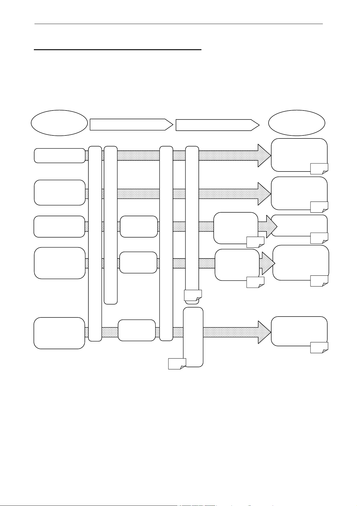
【KW8M (AKW8111)】
Basic setting to measure by Eco-POWER METER
When wiring the main unit and the current transformer (CT) and setting the basic setting after power on,
you can measure the power
The basic setting of MODE1 is necessary to measure.
In order to use the other functions, the settings of the each parameter are necessary.
What to do
Measure Power
Measure
ON-time and
OFF-time
Output Alarm
Collect data
via RS485
Count pulse
output from
other device
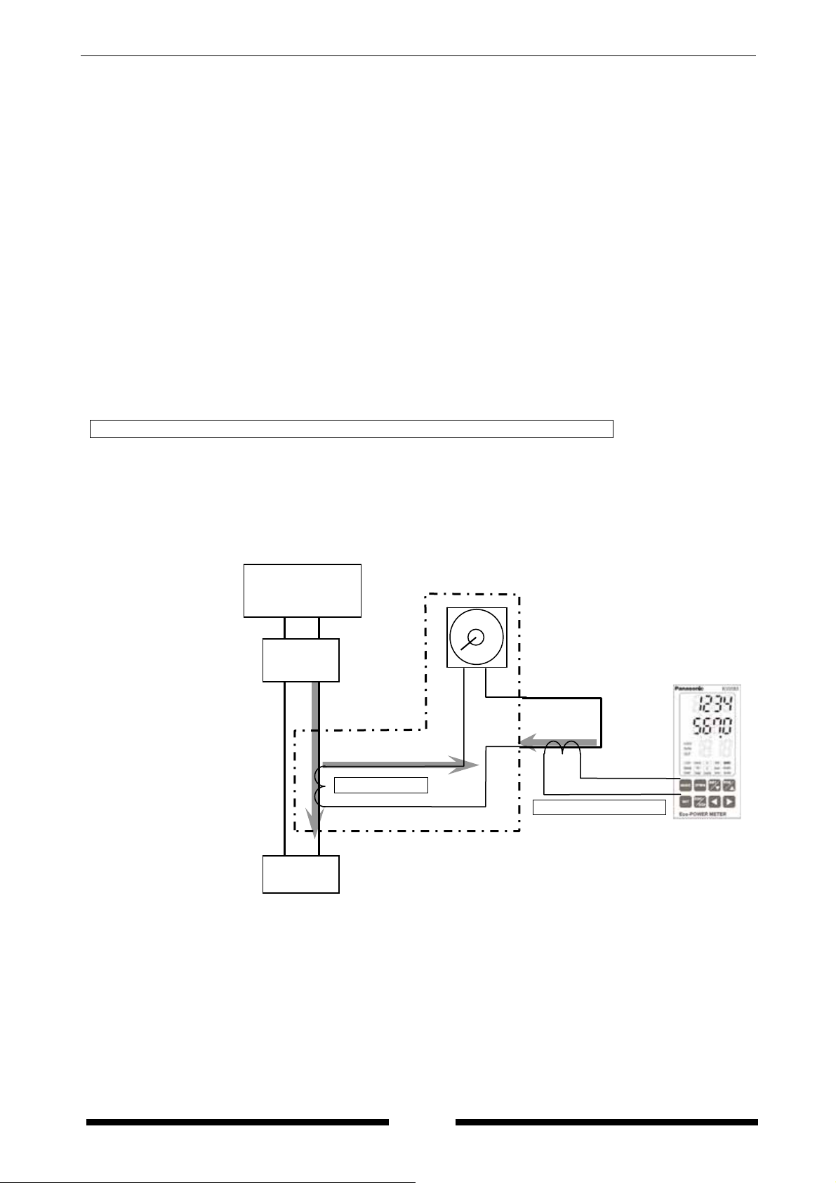
Mount / Connection
Connect the current transformer (CT)
Wire the main unit
Wire output
line
Wire
communication
Wire input
line
Set the basic settings (MODE1)
Power on the main unit
p.15
pulse measurement
p.22
Settings
Set the parameter for
Set alarm
output
(MODE1)
p.15
Set
communication
setting
(MODE3)
p.23
Check measured
data with power
monitoring mode
Check measured
time with power
monitoring mode
Check measured
Check count value
monitoring mode
How to use
6.2
6.2
Check alarm
output
5.3
data via
communication
device
7
with power
6.2
KW8M Eco-POWER METER
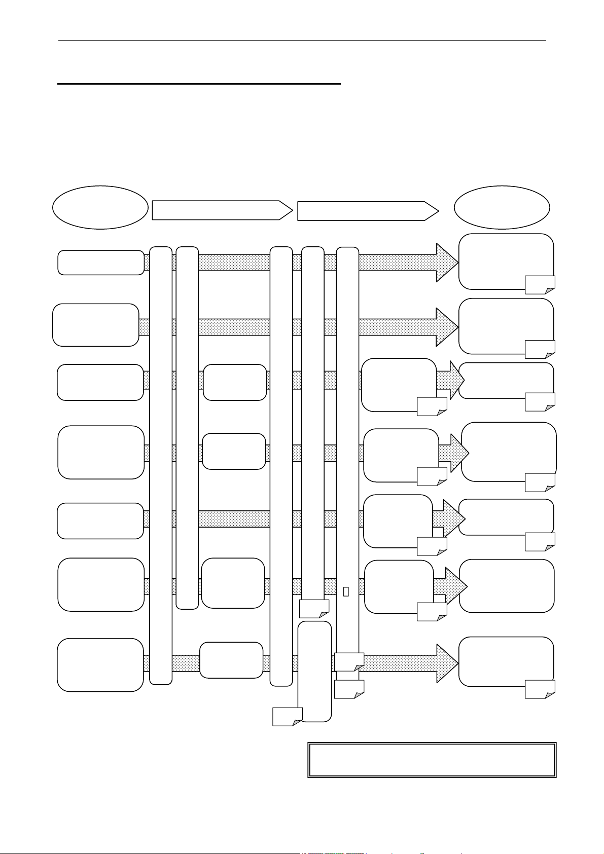
【KW8M with log function (AKW8111H)】
Basic setting to measure by Eco-POWER METER
When wiring the main unit and the current transformer (CT) and setting the basic setting after power on,
you can measure the power
The basic setting of MODE1 is necessary to measure.
In order to use the other functions, the settings of the each parameter are necessary.
What to do
Measure Power
Measure
ON-time and
OFF-time
Output Alarm
Collect data
via RS485
Log data
Read out
log data
Count pulse
output from
other device
*Be sure to set calendar timer (clock) and
Mount / Connection
Connect the current transformer (CT)
Wire output
line
Wire the main unit
Wire
communication
Prepare
the tool
software
Wire input
line
Set the basic settings (MODE1)
Power on the main unit
p.15
Set the parameter for
pulse measurement
p.22
initialize memory of main unit before measuring.
Settings
Check measured
data with power
monitoring mode
Initialize memory of main unit (MODE4) and set calendar timer (
Check measured
time with power
monitoring mode
Set alarm
output
(MODE1)
communication
setting
(MODE3)
Set log
setting
Set
p.15
Check measured
p.23
Check log data
with option mode
(MODE4)
p.26
*
) (MODE5)
p.26
p.28
Set log
setting
(MODE4)
p.26
After measuring,
read out by using
Check count value
monitoring mode
How to use
6.2
6.2
Check alarm
output
5.3
data via
communication
device
7
6.3
software
with power
6.2
KW8M Eco-POWER METER
Cautions for Your Safety
Read the manual carefully before installing, running and maintenance for proper operation.
Before using, master the knowledge of the equipment, safety information and all of other
notes.
This manual uses two safety flags to indicate different levels of danger.
WARNING
●Always take precautions to ensure the overall safety of your system, so that the whole
system remains safe in the event of failure of this product or other external factor.
●Do not use this product in areas with inflammable gas. It could lead to an explosion.
●Exposing this product to excessive heat or open flames could cause damage to the
lithium battery or other electronic parts.
CAUTION
●To prevent abnormal exothermic heat or smoke generation, use this product at the
values less than the maximum of the characteristics and performance that are assured
in these specifications.
●Do not dismantle or remodel the product. It could lead to abnormal exothermic heat or
smoke generation.
●Do not touch the terminal while turning on electricity. It could lead to an electric shock.
●Use the external devices to function the emergency stop and interlock circuit.
●Connect the wires or connectors securely. The loose connection might cause abnormal
exothermic heat or smoke generation.
●Do not allow foreign matters such as liquid, flammable materials, metals to go into the
inside of the product. It might cause exothermic heat or smoke generation.
●Do not undertake construction (such as connection and disconnection) while the power
supply is on.
●Do not use at secondary side circuit of inverter. It might cause exothermic heat or
damage.
A handling error could cause serious physical injury to an operator
and in the worst case could even be fatal.
A handling error could cause serious physical injury to an operator
or damage to the equipment.
Copyright and trademark
●Panasonic Electric Works, Co., Ltd. owns the copyright of this manual.
●We stiffly refuse the reproduction of without permission from this manual.
●Modbus Protocol is a communication protocol that the Modicon Inc.developed for PLC.
●Other company names and the product names are the trademarks or registered
trademarks of each company.

KW8M Eco-POWER METER
Introduction
Thank you very much indeed for purchasing
“KW8M Eco-POWER METER”.
In this manual, we explain the usage of “KW8M
Eco-POWER METER” in detail.
Please use it correctly after understanding the content
enough.

KW8M Eco-POWER METER
Table of Contents
Cautions before using ............................................................................................................................ⅰ
Chapter 1 Unit’s Features and Structure
1-1 Features................................................................................................................................................... 1
1-2 Unit’s Name and Part Numbers............................................................................................................... 1
1-2-1 Main unit......................................................................................................................................... 1
1-2-2 Dedicated Current Transformer (CT)............................................................................................. 1
1-2-3 Options........................................................................................................................................... 1
1-3 Measurement items ................................................................................................................................. 2
Chapter 2 Parts Name and Working
2-1 Parts Names ............................................................................................................................................ 3
2-2 Select Keys’ Functions ............................................................................................................................ 3
Chapter 3 Wi
3-1 Main unit terminal arrangement............................................................................................................... 4
3-2 Wiring Diagrams ...................................................................................................................................... 5
3-3 For input connection ................................................................................................................................ 9
3-4 For Output connection ............................................................................................................................. 9
3-5 RS485 Communication.......................................................................................................................... 10
3-6 Low Voltage Directive............................................................................................................................ 11
Chapter 4 S
4-1 Operation procedure.............................................................................................................................. 12
4-2 Setting Mode Explanation...................................................................................................................... 15
4-2-1 MODE1 ........................................................................................................................................ 15
4-2-2 MODE2 ........................................................................................................................................ 22
4-2-3 MODE3 ........................................................................................................................................ 23
4-2-4 MODE4 ........................................................................................................................................ 26
4-2-5 MODE5 ........................................................................................................................................ 28
Chapter 5 Various Functions
5-1 LOCK mode ........................................................................................................................................... 29
5-2 Display while communication ................................................................................................................ 29
5-3 Display when pulse output..................................................................................................................... 29
5-3-1 Output depends on integrated electric power.............................................................................. 30
5-3-2 Instantaneous electric power alarm............................................................................................. 30
5-3-3 Current alarm ............................................................................................................................... 30
5-3-4 Stand-by power alarm.................................................................................................................. 30
5-3-5 Output depends on count value................................................................................................... 30
5-4 Counter function .................................................................................................................................... 31
Chapter 6 Display of each Value
6-1 Working of Monitor Display.................................................................................................................... 32
6-2 Outline for the Working of Power Monitoring Mode Display.................................................................. 33
6-2-1 Integrated Electric power ............................................................................................................. 34
6-2-2 Instantaneous Electric power....................................................................................................... 35
6-2-3 Current ......................................................................................................................................... 35
6-2-4 Voltage......................................................................................................................................... 36
6-2-5 Electricity Charge......................................................................................................................... 37
6-2-6 Power factor................................................................................................................................. 37
6-2-7 Frequency .................................................................................................................................... 38
6-2-8 Hour meter ................................................................................................................................... 38
6-2-9 Counter ........................................................................................................................................ 39
6-3 Outline for the Working of Option Mode Display (only for AKW8111H) ................................................ 41
6-3-1 Monthly integrated electric power (only for AKW8111H)............................................................. 42
6-3-2 Daily integrated electric power (only for AKW8111H) ................................................................. 43
6-3-3 Hourly integrated electric power (only for AKW8111H) ............................................................... 44
6-3-4 Integrated electric power (active) for arbitrary period (only for AKW8111H)............................... 45
6-3-5 Calendar Timer (only for AKW8111H) ......................................................................................... 45
ring ......................................................................................................................................4
ettings..................................................................................................................................12
..................................................................................................................29
............................................................................................................32
..................................................................................................1
.........................................................................................................3

KW8M Eco-POWER METER
Chapter 7 MEWTOCOL Communications
7-1 Communication Procedures .................................................................................................................. 46
7-2 Communication timing ........................................................................................................................... 46
7-3 MEWTOCOL Communication ............................................................................................................... 47
7-3-1 Overview of MEWTOCOL-COM (RS485).................................................................................... 47
7-3-2 Data Register List ........................................................................................................................ 48
7-3-3 Error Codes.................................................................................................................................. 51
7-3-4 Command..................................................................................................................................... 51
7-4 MODBUS (RTU) Communication .......................................................................................................... 53
7-4-1 Overview of MODBUS (RTU) ...................................................................................................... 53
7-4-2 Data Register List ........................................................................................................................ 56
Chapter 8 Battery for Memory Backup (only for AKW8111H)
8-1 Setting before using............................................................................................................................... 61
8-2 How to Replace Battery......................................................................................................................... 61
8-3 How to Remove ..................................................................................................................................... 62
8-4 How to Mount......................................................................................................................................... 62
Chapter 9 Specifications.........................................................................................................................
9-1 Main unit ................................................................................................................................................ 63
9-2 Input Specifications ............................................................................................................................... 64
9-2-1 Electric power input...................................................................................................................... 64
9-2-2 Pulse input ................................................................................................................................... 64
9-3 Pulse output (Transistor output) Specifications..................................................................................... 65
9-4 Communication Specifications .............................................................................................................. 65
9-5 Option Specifications (only for AKW8111H).......................................................................................... 66
9-6 Dedicated Current Transformer Specifications ..................................................................................... 67
9-7 Self-diagnostic function ......................................................................................................................... 67
9-8 Power Failure Memory .......................................................................................................................... 67
Chapter 10 Mounting
10-1 Dimensions .......................................................................................................................................... 68
10-1-1 Main unit..................................................................................................................................... 68
10-1-2 Dedicated CT ............................................................................................................................. 69
10-2 Panel cutout......................................................................................................................................... 71
10-3 Panel mounting.................................................................................................................................... 71
..............................................................................................................................68
..............................................................................................46
.................................................................61
63

KW8M Eco-POWER METER
Cautions before using
■ Installation environment
◇Do not use the Unit in the following environments.
・Where the unit will be exposed to direct sunlight and where the ambient temperature is outside
the range of -10 to 50 C.
・Where the ambient humidity is outside the range of 30 to 85 % RH (at 20℃ non-condensing)
and where condensation might occur by sudden temperature changes
・Where inflammable or corrosive gas might be produced
・Where the unit will be exposed to excessive airborne dust or metal particles
・Where the unit will be exposed to water, oil or chemicals
・Where organic solvents such as benzene, paint thinner, alcohol, or strong alkaline solutions
such as ammonia or caustic soda might adhere to the product
・Where direct vibration or shock might be transmitted to the product, and where water might wet
the product
◇Please use the Unit according to the specifications described in this manual. Otherwise, it
may malfunction or cause fire and an electric shock.
・Connect to the power supply in compliance with the rating.
・Refer to the wiring diagram to ensure proper wiring for the power supply, input and output.
・Do not perform wiring or installation with a live line. It may also lead to circuit burnout or fire by
way of the secondary CT side opening.
・Do not add voltage and current to an output terminal from outside.
■ Installation
・Installation and wiring must be performed by expert personnel for electrical work or electric
piping.
・The power supply terminal and voltage input terminal of the main unit is common. Therefore if
additional noise effects the power supply line, incorrect measurements may result.
・Eco-POWER METER is designed to be used in a control panel.
・As to measurement
If there is some distortion by harmonic or waveform, it may not measure correctly.
Please check with the actual system before adopts it.
■ Static electricity
・Discharge static electricity touching the grounded metal etc. when you touch the unit.
・Excessive static electricity might be generated especially in a dry place.
■ Cleaning
・Wipe dirt of the main unit with soft cloth etc. When thinner is used, the unit might deform or be
discolored.
■ Power supply
・Connect a breaker to the voltage input part for safety reasons and to protect the device.
The breaker that connects to the voltage input part must arrange at the position easily reached,
and display shows it is the breaker of the equipment.
・Do not turn on the power supply or input until all wiring is completed.
■ Before power on
Please note the following points when turning on power at the first time.
・Confirm there are neither wiring rubbish nor especially an electrical conduction when installed.
・Confirm neither the power supply wiring, the I/O wiring nor the power-supply voltage are wrong.
・Tighten the installation screw and the terminal screw surely.
・Use an electric wire applicable to the rated current.
i


KW8M Eco-POWER METER
Chapter 1 Unit’s Features and Structure
1-1 Features
■With KW8M Eco-POWER METER, electrical power (voltage, current, etc.), power factor, frequency,
etc are measured using AC voltage and AC current input via one of the following systems:
single-phase two-wire system, single-phase three-wire system, three-phase three-wire system or
three-phase four-wire system.
This also works as an hour meter, that is measured power-on or power-off time, and as a counter that
is for pulse output equipment like flow meter.
■Eco-POWER METER is designed chiefly to manage saving energy. It is neither intended nor
can it be legally used for billing.
1-2 Unit’s Name and Part Numbers
1-2-1 Main unit
Model No
AKW8111 Not available
AKW8111H Available
(Common)
Phase and Wire
system
・Single-phase two-wire
・Single-phase three-wire
・Three-phase three-wire
・Three-phase four-wire
1-2-2 Dedicated Current Transformer (CT)
Rated primary current Model No
5A
50A
100A AKW4802
250A AKW4803
400A AKW4804
1-2-3 Options
Product name Model No Remarks
Terminal cover AKT8801 -----
Log function
Power
supply
100-240V
AC
50/60Hz
AKW4801
Measured
voltage input
・400VAC
・100/200VAC
Measured
current input
・ 50A
・100A
・250A
・400A
Current
transformer
Dedicated CT
type
(5A,50A(common)
/100A/250A/400A)
Terminal
type
Screw
Terminal
(M3 +/−
screw)
Spare Battery *1) AFC8801 Required to back up memory and calendar
*1) This is attached to AKW8111H when shipped.
1

KW8M Eco-POWER METER
1-3 Measurement items
Item Unit Data range
Integrated electric
power
Instantaneous
electric power
Active kWh 0.00 to 9999999.9
Reactive kvarh 0.00 to 9999999.9
Apparent kVAh 0.00 to 9999999.9
Active kW 0.00 to 999999.99
Reactive kvar -99999.99 to 0.00 to 999999.99
Apparent kVA 0.00 to 999999.99
CT1 A 0.0 to 6000
Current
Voltage
Electricity charge * 0.00 to 99999999
Power Factor
Frequency Hz 47.5 to 63.0
Hour meter
Pulse counter 0 to 99999999
*Eco-POWER METER is designed chiefly to manage saving energy.
It is neither intended nor can it be legally used for billing.
CT2 A 0.0 to 6000
CT3 A 0.0 to 6000
Between P1-P0 V 0.0 to 9999
Between P2-P0 V 0.0 to 9999
Between P3-P0 V 0.0 to 9999
Unit display
Communication
ON-time
OFF-time
hour 0.0 to 99999.9
0.00 to 1.00
(LEAD: Leading phase, LAG: lagging phase)
-1.00 to 0.00 to 1.00
(Within the range of phase angle θ=-90 to 0 to 90 degree)
2
KW8M Eco-POWER METER
Chapter 2 Parts Name and Working
2-1 Parts Names
①Display indicator ・Lighting or Blinking according to the display
②LOCK indicator ・Lighting while in lock mode
③T/R indicator ・Blinking while communication
④OUT indicator ・Lighting when pulse output
⑤Display each value ・Display each measured value
・Display each setting value
⑥MODE Key
⑦SET Key
⑧ITEM / △ Key
⑨SHIFT / ▽ Key
⑩Left / Right ( / ) Keys
⑪OPTION Key
⑤
②
③
④
①
⑥
⑦
⑨
⑧
⑫START/STOP Key
2-2 Select Keys’ Functions
Key Functions
<MODE>
<SET>
ITEM
<
SHIFT
<
< Left / Right ( / )>
<SET> + <MODE>
<SET>
(continuous press 3-sec)
<OPTION>
△
▽
>
>
・Use to select mode
・Use to set each value entered
・To select measured display
・To shift each mode
・To change each setting value
・To select measured display
・To shift each mode
・To change each setting value
・To change each setting value
・To reset the measured value
・All keys locked
・Release lock mode while in lock mode
・To shift power monitoring mode and option mode (Only AKW8111H)
⑪
⑫
⑩
<START/STOP>
・To start and stop measuring integrated electric power (active)
for arbitrary period. (from press this key until press it again)
(Only AKW8111H)
3
KW8M Eco-POWER METER
Chapter 3 Wiring
3-1 Main unit terminal arrangement
Function No. Function
Power
Supply
Pulse
Input
Pulse
Output
RS485
N.C.
L
N
+
−
+
−
+
−
E
①
②
③
④
⑤
⑥
⑦
⑧
⑨
⑩
⑪
⑫
⑬
⑭
P1
P0
P2
P3
Measured
voltage
input
⑮ CT1 (+) ⑤ ⑮
⑯ CT1 (−) ⑥ ⑯
⑰ CT2 (+) ⑦ ⑰
⑱ CT2 (−) ⑧ ⑱
Measured
CT
input
⑲ CT3 (+) ⑨ ⑲
⑳ CT3 (−)
The input voltage to each terminal is as follows.
Terminal Phase and wire Terminal Input voltage
Back view
① ⑪
② ⑫
③ ⑬
④ ⑭
⑩
⑳
Operating
power supply
Measured
voltage input
Single-phase,
two-wire
Single-phase,
two-wire
Single-phase,
three-wire
Three-phase,
three-wire
Three-phase,
four-wire
②−③ 100-240VAC (100 - 240V〜)
⑪−⑫
⑪−⑫−⑬
⑪−⑫−⑬
⑪−⑫−⑬−⑭
0-440VAC ( 0-440V〜)
0-220VAC ( 0-220V〜:3W)
0-440VAC ( 0-440V 3〜)
0-254VAC ( 0-254V 3N〜)
(Line voltage)
(Line voltage)
(Phase voltage)
(Line voltage)
(Phase voltage)
Caution for Wiring
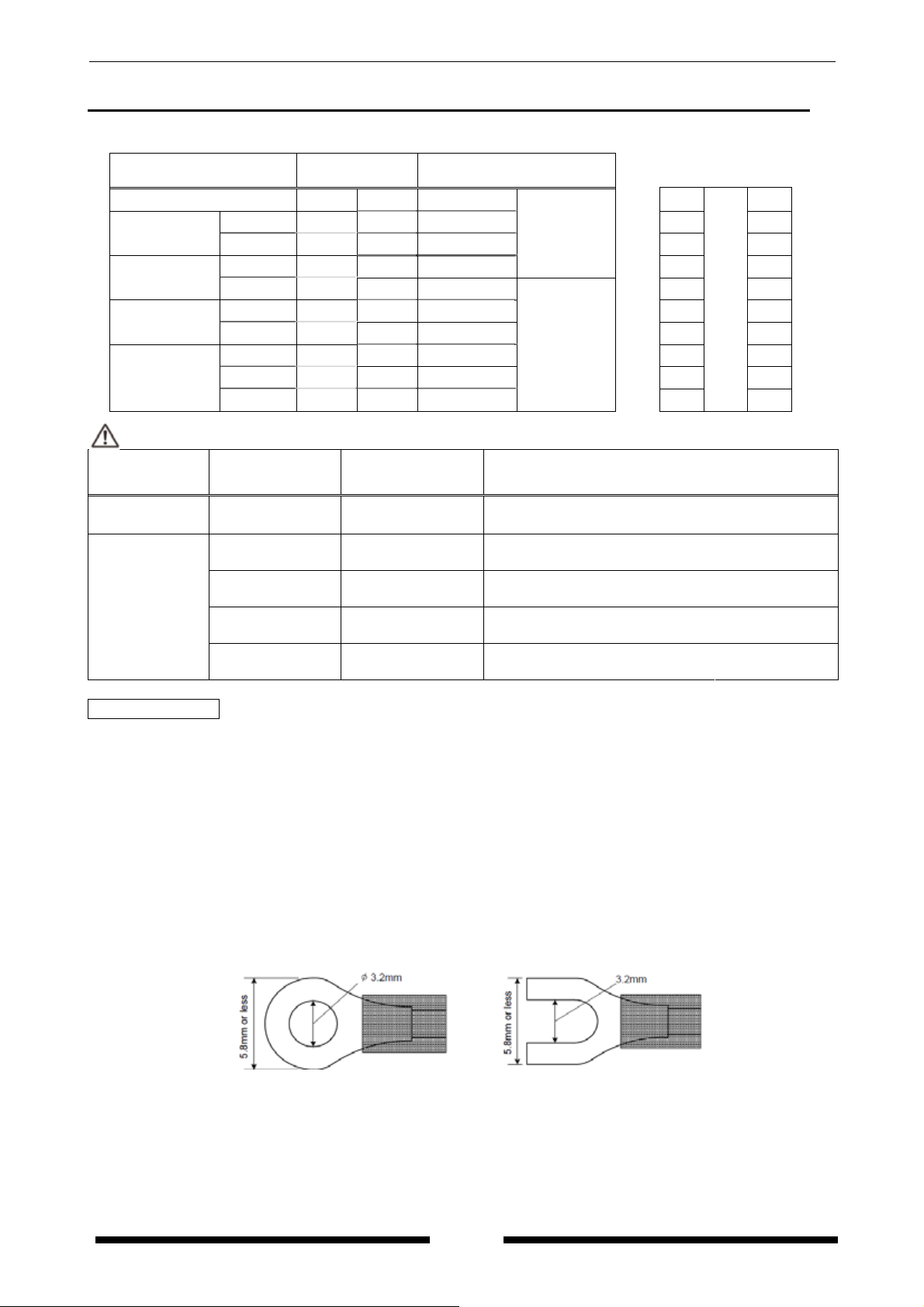
1) Terminal fastening torque should be 0.6 to 1.0N・m.
2) This has no built-in power switch, circuit breaker for power supply part. To protect the device, it is
necessary to install power switch and circuit breaker in the power supply circuit.
And this has no built-in power switch, circuit breaker or fuse for measured voltage input parts.
Therefore it is necessary to install them in the circuit near this unit.
3) The terminal block of KW8M is designed to be wired from left. Insert wires to the terminal from the
left and fasten with terminal screws.
4) In case using insulation sleeve, use an insulation sleeve applicable to M3 screw. Fastening torque
should be 0.6 to 1.0N・m. (Refer to the below.)
5) We recommend a wire with the cross section of 0.75 to 1.25mm
2
for power supply line and measured
voltage input line.
6) Use flame-resistant cable for each wiring.
4
KW8M Eco-POWER METER
3-2 Wiring Diagrams
・Please connect a breaker to power supply and voltage input part for safety reasons and to protect the
device.
・Grounding the secondary side of VT and CT is not necessary with low-voltage circuit.
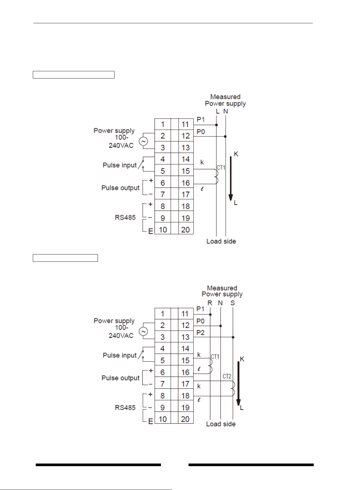
Single-phase two-wire system
One current transformer (CT) is required to measure single-phase two-wire system.
Single-phase three-wire
Two CTs are required to measure single-phase three-wire system.
Wire by diagram of single-phase 2-wire system when measure load using R-S with single-phase 3-wire
system.
5
KW8M Eco-POWER METER
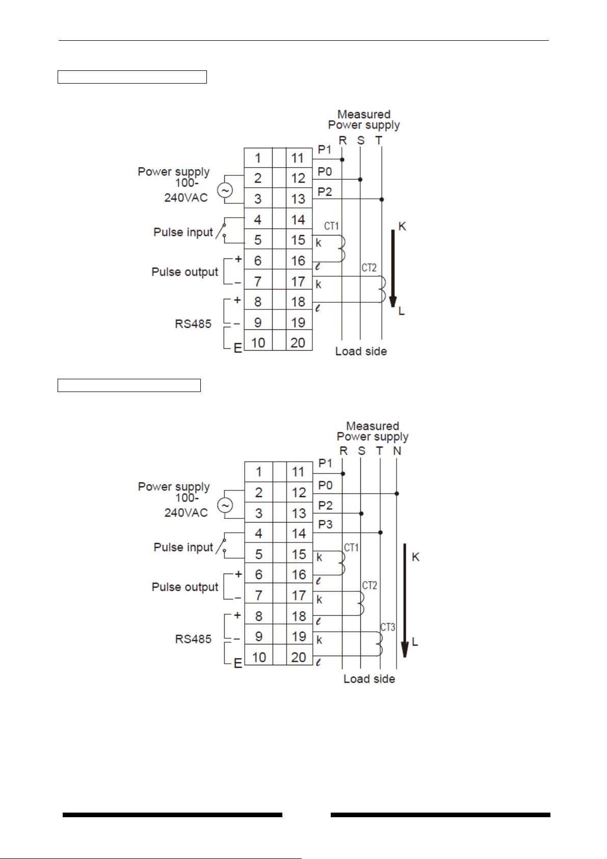
Three-phase three-wire system
Two CTs are required to measure three-phase three-wire system.
Three-phase four-wire system
Three CTs are required to measure three-phase four-wire system.
6
KW8M Eco-POWER METER
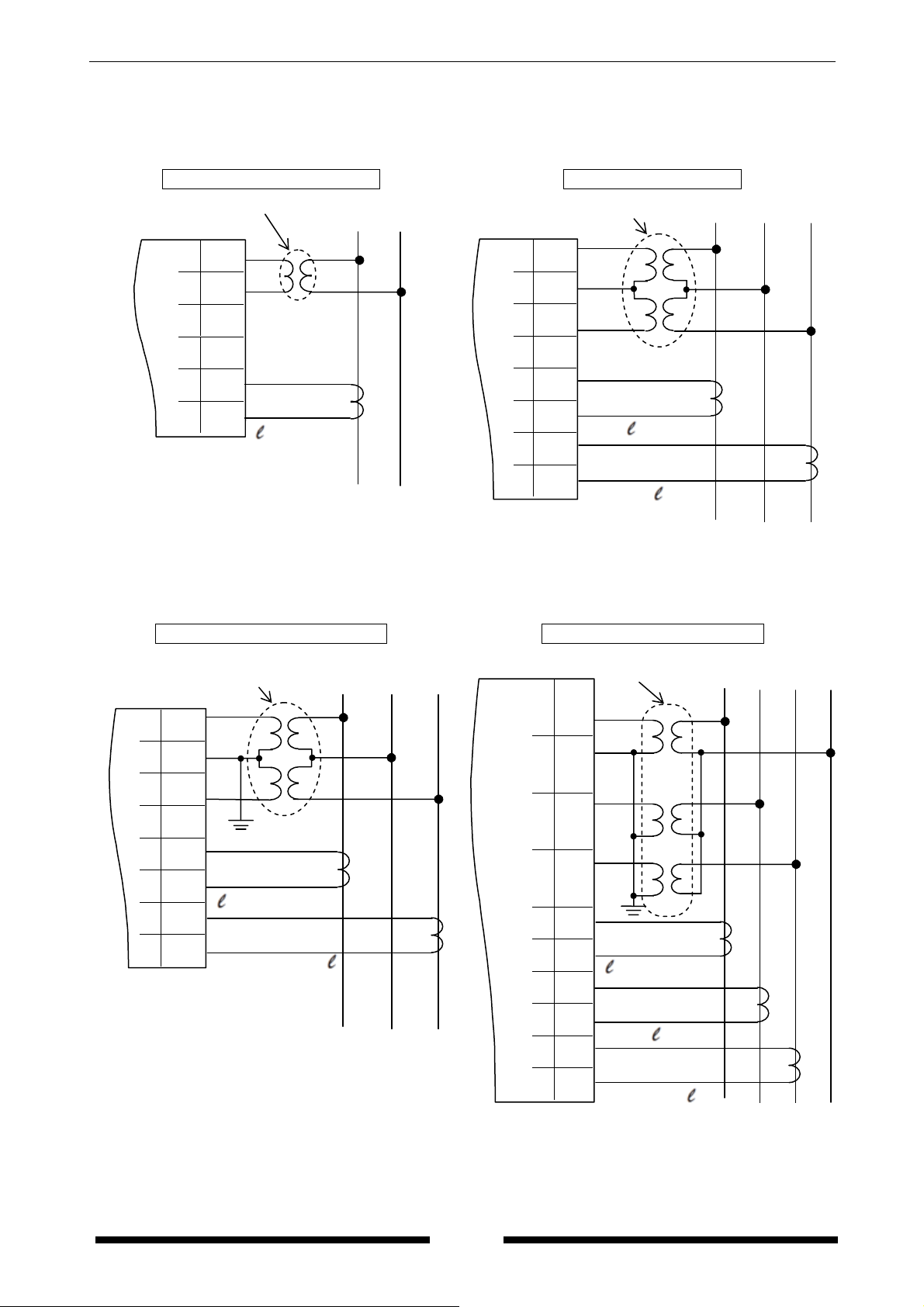
◇VT (Voltage transformer) is required when you measure a load with voltage 440V or more system.
Use VT with those secondary rating is 110V.
Grounding the secondary side of VT and CT is not necessary with low-voltage circuit.
Single-phase two-wire system
11
12
13
VT
P1
P0
L N
Single-phase, three-wire
VT
P1
11
P0
12
13
P2
R
N
S
14
15
16
k
l
CT1
14
15
16
17
18
k
CT1
l
k
CT2
l
No.13,14,17〜20 are not wired.
No.14, 19, 20 are not wired.
Three-phase, three-wire system
Three-phase, four-wire system
P1
P0
P2
P3
k
VT
R S T N
k
CT1
CT2
k
11
12
13
P1
P0
P2
VT
S
R
T
11
12
14
15
16
17
18
k
k
CT1
CT2
13
14
15
16
17
18
19
No.14, 19, 20 are not wired.
20
CT3
7
KW8M Eco-POWER METER
A
◇How to attach the Current Transformer (CT)
・One CT is required to measure 1P2W system. Two CTs are required to measure a 1P3W system or
3P3W system. Three CTs are required to measure 3P4W system. Using all CTs should be the same.
・Check beforehand that the thickness of the electric wire is smaller than the through-hole of the CT.
・When connecting CT, connect the secondary side to the terminal of the main unit first, and after that
wire the primary side to a load electric wire. Incorrect order might cause an electric shock or break CT.
・The CT has polarity. Wire correctly according to the K and L marks. Wrong direction can’t measure
correctly.
・When closing CT, check that there is no foreign materials on the divided face. And make sure it is
closed securely once the wire is in place; if not the measurement value will be not accurate.
・When CTʼs cable is extended, it is possible to extend up to about 10m with the cable of AWG#22 or
more cross section under the environment without noise at all. Please use the thick cable as much as
possible.
◇To connect CT with secondary current 5A
How to connect the unit to measure by combination with existing commercial CT
(1) Select 5A at CT type setting mode (CT-T).
(2) Set the primary current of measured commercial CT (secondary current 5A) at primary side
current of CT setting mode (CT-1).
< ex > If the measured CT is 400A/5A, set to ”400”.
(3) Clamp the dedicated CT for 5A (AKW4801), which is connected to the main unit first, to
secondary side of the commercial CT. CT direction (K→L) should be set for the commercial CT
direction.
(Connection example)
Power supply
Breaker
mmeter etc.
Eco-POWER METER
Secondary current
K
Commercial CT
5A
L
L K
Dedicated CT (For 5A)
AKW4801
Load
8
KW8M Eco-POWER METER
3-3 For input connection
◇Input connection
・Contact input
Use highly reliable metal plated contacts. Since the contact’s bounce time leads directly to error in
the count value, use contacts with as short a bounce time as possible. In general, select 30Hz for
max.counting speed.
・Non-contact input (Transistor input)
Connect with an open collector. Use the transistor with the following specifications.
=20V min. IC=20mA min. I
V
CEO
=6μA max
CBO
Use transistors with a residual voltage of less than 1.5V when the transistor is ON.
※Short-circuit impedance should be less than 1kΩ.
(When the impedance is 0Ω, drain current is approx. 7mA.)
Open-circuit impedance should be more than 100kΩ.
・Input wiring
Please wire as short as possible by using a shielded wire or a metallic electric wire tube individually.
(Caution)
Operating power supply input part and measured voltage input are not insulated to pulse input parts.
So the input equipment must have the power supply transformer in which the secondary side is not
grounded with the primary and secondary sides insulated, in order to prevent interference of the
power supply circuit when connecting the external input circuit. Be sure not to use an
auto-transformer.
Operating po wer supply
or
Measured voltage input
(Fig.A)
Good example
Insulated
transformer
(−)
(+)
Input equipment
(sensor etc.)
Eco-POWER
METER
Operating power supply
Measured voltage input
or
Insulated
transformer
Eco-POWER
METER
Do not ground the secondary side.
(−)
(Fig.B) No Good example
Input equipment
(+)
(sensor etc.)
Operating power supply
Measured voltage input
or
Do not use an auto-transformer.
Auto transformer
Eco-POWER
METER
(+)
(−)
Input equipment
(sensor etc.)
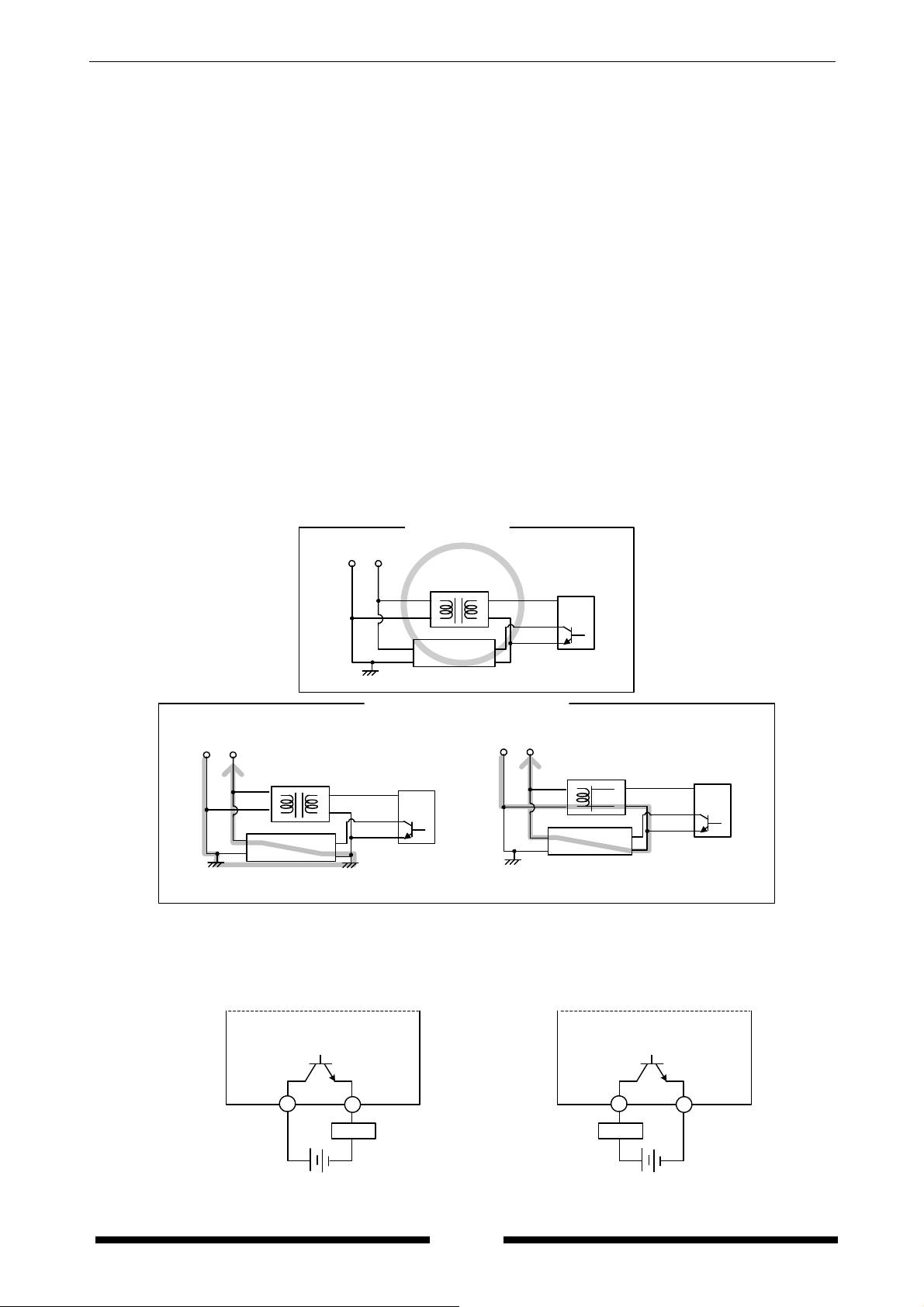
3-4 For Output connection
Since the transistor output is insulated from the internal circuit by a photo-coupler, it can be used both
as a NPN output and PNP (equal value) output.
Eco-POWER METER
NPN output
Pulse
(+)
6
Power supply for Load
7
Load
-+
Pulse
(-)
PNP output
Eco-POWER METER
Pulse
(+)
6
Load
Power supply for Load
Pulse
(-)
7
-+
9
KW8M Eco-POWER METER
3-5 RS485 Communication
・When using shielded cable for the RS485 transmission line, ground one end.
Use a class D dedicated earth for grounding. Do not share a ground with other earth lines. (Fig.1)
・Be sure to connect with daisy chain the RS485 transmission line between each unit.
Do not use a splitter. (Fig.2)
・With a terminal station, RS485 (E) (No.10) and RS485 (-) (No.9) should be shorted.
(Fig.1)
To RS-485 device
Sheilded cable
(Fig.2)
Correct wiring
○
Incorrect wiring
×
Recommended Cable
Use the transmission cables shown below for Eco-POWER METER RS485 communication system.
Conductor Insulator
Cable
Twisted-
Size
1.25 mm
(AWG16)
or more
Resistance
(at 20℃)
2
Max.16.8Ω/km
pair
with shield
0.5 mm
(AWG20)
2
Max.33.4Ω/km
or more
2
Max.25.1Ω/km
VCTF
0.75 mm
(AWG18)
or more
Cable Section
Shield
Twisted-pair
with shield
Conductor Insulator
Eco-POW ER METER
General station
(+) (+)
(−)(E) (−)(E)
Sheilded cable
Class D grounding Class D grounding
Terminal Terminal
Eco-POWER METER
Terminal station
Cable
Material Thickness
Polyethylene
Polyethylene
PVC
Max.
0.5 mm
Max.
0.5 mm
Max.
0.6 mm
diameter
Approx.
8.5 mm
Approx.
7.8 mm
Approx.
6.6 mm
Notes
Jacket
1) Use shielded type twist cables.
2) Use only one type of the transmission cables.
2) Do not mix different types of the cables.
3) Use twist pair cables under a bad noise environment.
Shorted
Applicable cable
HITACHI
KPEV-S
1.25 mm
2
×1P
Belden Inc. 9860
HITACHI
KPEV-S
0.5 mm
2
×1P
Belden Inc. 9207
VCTF
0.75 mm
2
×2C
(JIS)
VCTF
Jacket
Conductor Insulator
10

KW8M Eco-POWER METER
3-6 Low Voltage Directive
When using in the application confirming to EN61010-1/IEC61010-1, make sure to satisfy the following
conditions.
(1) Pulse output part and communication part secure only basic insulation. In order to secure reinforced
(double) insulation demanded by EN 61010-1/ IEC61010-1, secure basic insulation or more with
load side for output part and secure basic insulation or more with communication system side for
communication part.
(2) Provide the voltage input part with an EN60947-1 or EN60947-3 compliant circuit breaker.
The breaker that connects to the voltage input part must arrange at the position easily reached,
and display shows it is the breaker of the equipment.
(3) Use a wire with basic insulation or more for a wire cramped (or connected) CT.
【Environmental conditions】
・Overvoltage category Ⅱ, Pollution degree 2
・Indoor use
・An ambient temperature of –10 to 50℃
・An ambient non-condensing humidity of 35 to 85%RH (at 20℃)
・Altitude of 2000m or less
【Mount the product in a place with】
・A minimum of dust, and an absence of corrosive gases
・No flammable, explosive gasses
・Few mechanical vibrations or shocks
・No exposure to direct sunlight
・No large capacity electromagnetic switches or cables through which large current is flowing
11
KW8M Eco-POWER METER
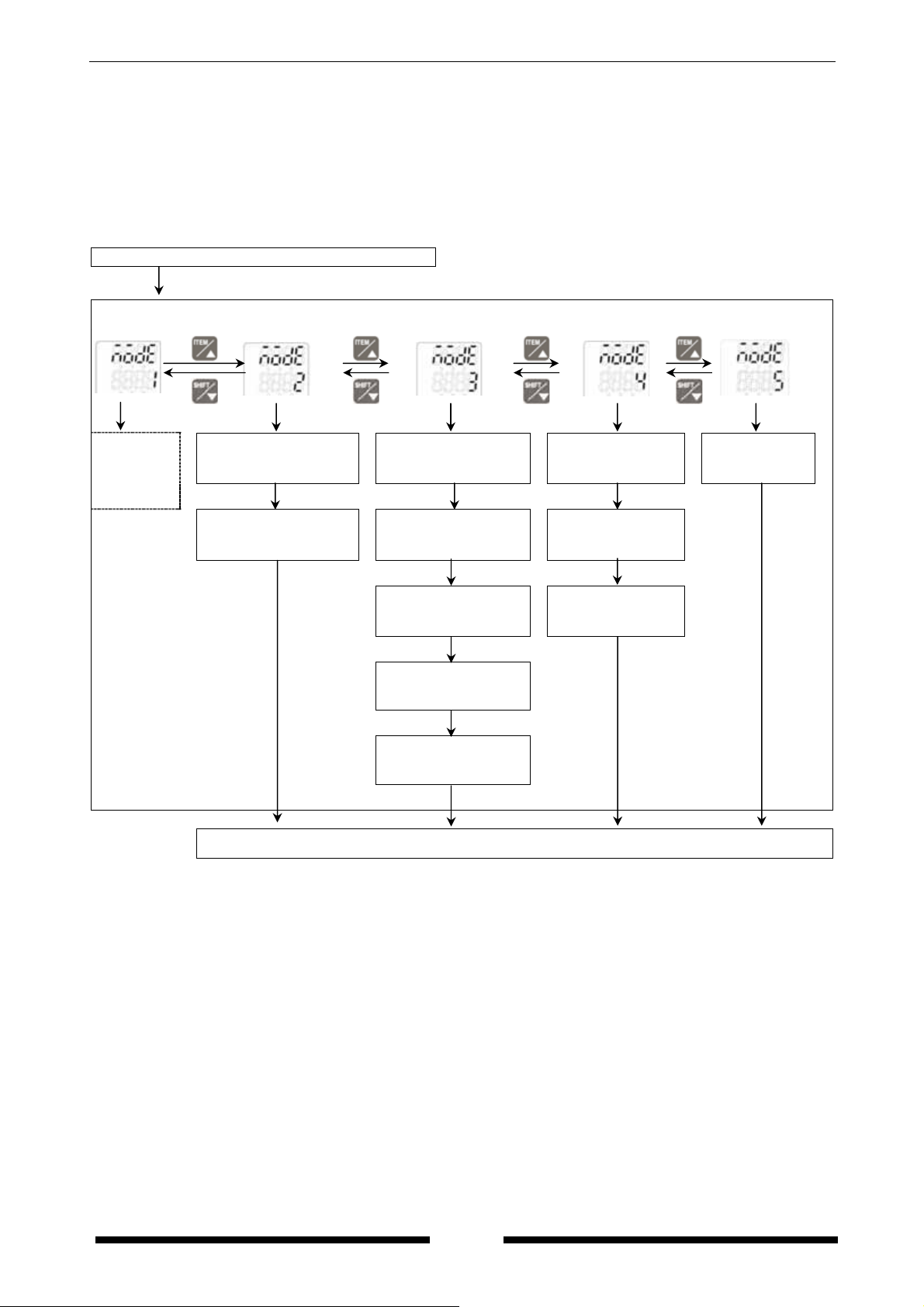
Chapter 4 Settings
4-1 Operation procedure
Mode 1…Mode for setting each parameter for power measurement
Monitor (Display when power on)
(Mode 1)
Setting mode
<MODE>
(Mode 2) (Mode 3) (Mode 4)
(Mode 4) *1
<SET>
Phase/Wire system setting mode
SYST
CT type setting mode
<SET>
CT-T
Voltage range setting mode
VT setting mode
When select
other than “5A”
<SET>
VOLT
<SET>
VT
Current for time
measurement setting mode
Cutoff current setting mode
<SET>
HM-A
<SET>
When select
<SET> <SET> <SET> <SET>
“5A”
<SET>
<SET>
CUTA
Unit for pulse output setting mode
<SET>
PL-P
When select
“Values”
<SET>
When select “AL-P”
<SET>
Power alarm setting
mode
AL-P
<SET> <SET>
Electricity rate setting mode
When select “AL-C”
Current alarm setting
mode
AL-C
<SET>
RATE
<SET>
Monitor
Press <MODE> to return Monitor.
Refer to the next page.
Primary side current of
CT setting mode
CT-1
When select “AL-S”
<SET>
Stand-by alarm setting
mode 1
ALS1
<SET>
Stand-by alarm setting
mode 2
ALS2
<SET>
When select “Cnt”
Preset value setting
mode
Cnt
<SET>
<SET>
12
KW8M Eco-POWER METER
Mode 2…Mode for setting of each parameter for pulse measurement
Mode 3…Mode for setting of each parameter for serial communication
Mode 4…Mode for setting of each parameter for optional function
Mode 5…Mode for setting of calendar timer
*For AKW8111H, be sure to set calendar timer (Mode 5) and initialize memory of main unit (Mode 4)
before measuring.
Monitor (Display when power on)
<MODE>
Setting mode
(Mode 1)
<SET>
Refer to
the
previous
page.
(Mode 2)
Max. measurement
speed setting mode
Hz
Prescale setting mode
PSCL
<SET> <SET> <SET> <SET>
<SET> <SET> <SET> <SET>
<SET> <SET> <SET>
<SET>
(Mode 3) (Mode 4)
Protocol setting mode
Auto-off setting mode
PROT
Station number
setting mode
NO.
Transmission speed
setting mode
SPD
Transmission format
setting mode
Log cycle
setting mode
LOG *1
Initialize memory of
main unit
S.FMT *1
(Mode 5) *1
Calendar timer
setting mode
OFF
CAL *1
FMT
<SET>
Response time
setting mode
RESP
<SET>
Monitor
Press <MODE> to return Monitor.
*1 Only for AKW8111H. It is not displayed for AKW8111.
13

KW8M Eco-POWER METER
◆Initial value list
Mode 1 Mode 2
Item Initial value Item Initial value
Phase/Wire system 1P2W
CT type 50
Max. measurement
speed
2000
Primary side current of CT 5 Prescale 1.000
Voltage range 400
VT 1.00
Current for time measurement
1.0 Mode 3
Cutoff current 1.0 Item Initial value
Unit for pulse output 0.001 Protocol MEWTOCOL
Power alarm 9999.99 Station number 1
Current alarm 100.0 Transmission speed 19200
Stand-by alarm1 100.00
Stand-by alarm 2 0
Transmission
format
8bit-o
Preset value 0 Response time 5
Electricity rate 10.00
Mode 4 Mode 5
Item Initial value Item Initial value
Auto-off 0
Log cycle *1 60
Initialize memory of
main unit *1
OFF
Calendar timer *1
2000 Jan. 1
00:00:00
*1 Only AKW8111H can be set.
It is not displayed for AKW8111.
14

KW8M Eco-POWER METER
4-2 Setting Mode Explanation
■The value with under line is initial setting among each setting value. ☆Set before measurement.
4-2-1 MODE1
(Mode for setting each parameter for power measurement.)
Phase/Wire system setting mode SYST
Mode defines phase and wire system to measure.
・Select from Single-phase 2-wire
*When Single-phase 3-wire or Three-phase 3-wire is selected, it doesn’t measure Single-phase 2-wire
system correctly. And when Three-phase 4-wire is selected, it doesn’t measure Single-phase 2-wire,
Single-phase 3-wire, Three-phase 3-wire system correctly. Select the accurate phase and wire system
according to the measured system.
CT type setting mode CT-T
Mode defines input current type of the dedicated CT.
・Select from the type of 5A/50A
・When the secondary current of CT is 5A, select “5A”.
Primary side current of CT setting mode CT-1
Mode defines primary side current when measuring by combination with existing CT, its
secondary current of 5A.
It is possible to use as the second step for combination with existing CT by selecting “5A” in
the CT type setting mode. In this case, it is necessary to set the primary side current.
・Primary side current of the existing CT can be set the range of 1 to 4000 (Initial 5
・When connecting 5ACT directly and measure with 5A range, set to “5”.
ex) If primary current of measured existing CT is 400A (secondary side is 5A), set to “400”.
Voltage range setting mode VOLT
Mode defines voltage range of Eco-Power Meter.
・Select from 400
・When it measures load of 400V system, select “400”.
When it measures load of 100/200V system, select “200”.
*In case measuring the load of 100/200V system with selecting “400”, the resolution will be down.
Select the correct voltage range.
VT setting mode VT
Mode defines voltage input method to the main unit, input voltage directly or uses a voltage
transformer (VT) (over 440V system).
・It can be set the range of 1.00
“1.00” should be set when voltage input directly without connecting VT.
“1.01 to 99.99” should be set when VT is used to input voltage.
Current for time measurement setting mode HM-A
Mode defines for time measured current. It measures ON-time and OFF-time by setting value.
・It can be set the range of 1.0%
ex) When 10.0 is set, the current exceeds 10.0%F.S is measured as ON-time, the current under
10.0%F.S is measured as OFF-time.
*Measured current is the current of L1 (CT1)-phase.
Cutoff current setting mode CUTA
Mode defines load current that does not measure (Cutoff current).
Use to avoid miss-measurement by wiring or induction noise at no-load.
0.00kW is displayed for instantaneous electric power, 0.0A is displayed for current. Integrated
electric power is not added.
・It can be set the range of 1.0%
ex) When set to 10.0, current under 10.0%F.S is not added.
/200.
/ Single-phase 3-wire / Three-phase 3-wire / Three-phase 4-wire.
/100A/250A/400A.
*This mode is only when “5A” is selected on CT type setting mode.
).
to 99.99.
to 100.0%F.S.
to 50.0%.
15

KW8M Eco-POWER METER
Unit for pulse output setting mode PL-P
Mode defines unit used for pulse output. It defines the unit of integrated electric power for
1-pulse output.
・Select from 0.001
When one of the “0.001/0.01/0.1/1/10/100” [kWh] is set, one pulse is output at reaching the setting
value.
When “AL-P” is set, alarm is output at the time when instantaneous electric power is over the setting
value.
When “AL-C” is set, alarm is output at the time when current is over the setting value.
When “AL-S” is set, alarm is output at the time when current is under the setting value and it passes
the setting time.
When “Cnt” is set, it output at the time when count value reaches preset value set by preset value
setting mode.
Power alarm setting mode AL-P
Mode defines instantaneous electric power used for alarm output.
・It is set the range of 0.00 to 999999.99
Current alarm setting mode AL-C
Mode defines the ratio of current used for alarm output. (Ratio for the rated current)
・It is set the range of 1.0 to 100.0
Stand-by alarm setting mode 1 ALS1
Mode defines the ratio of current used for threshold value to judge stand-by power.
(Ratio for the rated current)
・It is set the range of 1.0 to 100.0%.
Stand-by alarm setting mode 2 ALS2
Mode defines the time used for threshold value to judge stand-by power.
・It is set the range of 0
When “0” is set, alarm is always output at the time when judging the stand-by power.
When “1 to 9999” is set, alarm is output at the time when passing the setting time with the stand-by
power.
The alarm can be reset by pressing <SET> with the instantaneous electric power display. After reset
the alarm, start to monitor the stand-by power again.
Preset value setting mode Cnt
Mode defines count value used for output.
・It is set the range of (0×prescale setting value)
*This mode is only when “Cnt” is selected on unit for pulse output setting mode.
Electricity charge setting mode RATE
Mode defines electricity charge ratio used as a standard per 1kWh.
・It can be set the range of 0.00 to 99.99 /1kWh. (Initial 10.00)
/0.01/0.1/1/10/100kWh /AL-P/AL-C/AL-S/Cnt.
*Only when “AL-P” is selected on unit for pulse output setting mode.
kW.
*Only when “AL-C” is selected on unit for pulse output setting mode.
%.
*Only when “AL-S” is selected on unit for pulse output setting mode.
*Only when “AL-S” is selected on unit for pulse output setting mode.
to 9999min.
*Only when “Cnt” is selected on unit for pulse output setting mode.
to (99999999×prescale setting value).
16
 Loading...