

Panasonic KW4M Installation Manual

®
A
ARCT1F413E-2 '08.03
KW4M
Eco-Power Meter
User’s Manual
http://www.nais-e.com/
http://www.mew.co.jp/ac/e
Panasonic...the new name for
This manual was created using Adobe Acrobat.
Adobe, the Adobe logo, and Acrobat are trademarks
of Adobe Systems Incorporated.
KW4M Eco-Power Meter User’s Manual
ARCT1F413E ’05.6
RCT2F413E-1 '07.10
Matsushita Electric Works, Ltd.
Cautions for Your Safety
Read the manual carefully before installing, running and maintenance for proper operation.
Before using, master the knowledge of the equipment, safety information and all of other
notes.
This manual uses two safety flags to indicate different levels of danger.
WARNING
●If the use is predicted to lead to human injuries and/or grave expanding damage,
take the special safety measures such as double interlock.
●Do not use the product in the environment that has inflammable gas.
It might lead to an explosion.
CAUTION
●Tighten the wires firmly with terminal screws.
The bad connection might cause abnormal heat and smoke.
●Do not use the unit outside the range of the specifications regarding such as rating,
environment conditions etc.
It might cause abnormal heat or smoke.
●Do not discompose or modify the unit.
It might give you an electric shock or cause smoke.
A handling error could cause serious physical injury to an operator
and in the worst case could even be fatal.
A handling error could cause serious physical injury to an operator
or damage to the equipment.
●Do not touch the terminal while current is running.
It might give you an electric shock.

Introduction
Thank you for indeed for purchasing “KW4M Eco-POWER
METER” for this time.
In this manual, we explain the usage of “KW4M
Eco-POWER METER” in detail.
Please use it correctly after understanding the content
enough.

Table of Contents
Cautions before using ............................................................................................................................ⅰ
Chapter 1 Unit’s Features and Structure..............................................................................................1
1-1 Features................................................................................................................................................... 1
1-2 Unit’s Name and Part Numbers............................................................................................................... 1
1-2-1 Main unit......................................................................................................................................... 1
1-2-2 Dedicated Current Transformer (CT)............................................................................................. 1
1-2-3 Options........................................................................................................................................... 1
1-3 Measurement items................................................................................................................................. 2
Chapter 2 Parts Name and Working....................................................................................................3
2-1 Parts Names............................................................................................................................................ 3
2-2 Select Keys’ Functions ............................................................................................................................ 3
Chapter 3 Display of each Value..........................................................................................................4
3-1 Instantaneous electric power / Integrated Electrical energy.................................................................... 4
3-2 Current..................................................................................................................................................... 5
3-3 Voltage..................................................................................................................................................... 5
3-4 Electricity Charge..................................................................................................................................... 6
3-5 Hour Meter............................................................................................................................................... 6
3-6 Count Value / Preset Value..................................................................................................................... 7
Chapter 4 Various Functions................................................................................................................8
4-1 LOCK mode............................................................................................................................................. 8
4-2 CT Direction Notification (POWER Measurement).................................................................................. 8
4-3 Counter function (PULSE measurement)................................................................................................ 8
4-3-1 Operation mode............................................................................................................................. 8
4-3-2 Change the Preset Value............................................................................................................... 8
Chapter 5 Settings ...............................................................................................................................9
5-1 Operation procedure................................................................................................................................ 9
5-2 Setting Mode Explanation...................................................................................................................... 10
5-2-1 MODE (Select input method)....................................................................................................... 10
5-2-2 MODE1 ........................................................................................................................................ 10
5-2-3 MODE2 ........................................................................................................................................ 13
5-2-4 MODE3 ........................................................................................................................................ 14
5-2-5 MODE4 ........................................................................................................................................ 15
Chapter 6 Installation and Wiring.......................................................................................................16
6-1 Panel Cut-out dimensions .....................................................................................................................16
6-2 Panel mounting diagram........................................................................................................................ 16
6-3 Wiring..................................................................................................................................................... 17
6-3-1 Terminal arrangement.................................................................................................................. 17
6-3-2 Power measurement.................................................................................................................... 17
6-3-3 Pulse measurement..................................................................................................................... 20
6-3-4 For Output connection .................................................................................................................21
6-3-5 For Wiring terminal....................................................................................................................... 21
6-3-6 RS-485 communication................................................................................................................ 21
6-3-7 Low Voltage Directive.................................................................................................................. 22
Chapter 7 Communications....................................................................................................................23
7-1 Communication Procedures.................................................................................................................. 23
7-2 Communication timing........................................................................................................................... 23
7-3 MEWTOCOL communication................................................................................................................ 24
7-3-1 Overview of MEWTOCOL-COM (RS-485) ..................................................................................24
7-3-2 Data Register List ........................................................................................................................25
7-3-3 Error Codes.................................................................................................................................. 26
7-3-4 Command..................................................................................................................................... 26
7-5 MODBUS (RTU) Communication.......................................................................................................... 28
7-5-1 Overview of MODBUS (RTU) ...................................................................................................... 28
7-4-2 Data Register List ........................................................................................................................31

Chapter 8 Specifications......................................................................................................................33
8-1 Main unit................................................................................................................................................ 33
8-2 Input Specifications ............................................................................................................................... 34
8-2-1 Power Input.................................................................................................................................. 34
8-2-2 Pulse input specifications............................................................................................................. 35
8-3 Pulse output (Transistor output) Specifications..................................................................................... 35
8-4 Communication Specifications .............................................................................................................. 36
8-5 Dedicated Current Transformer Specifications ..................................................................................... 36
8-6 Self-diagnostic function ......................................................................................................................... 37
Chapter 9 Dimensions .........................................................................................................................37
9-1 Main unit................................................................................................................................................ 37
9-2 Dedicated CT......................................................................................................................................... 37
9-2 Dedicated CT......................................................................................................................................... 38


Cautions before using
■ Installation environment
◇Do not use the Unit in the following environments.
・Where the unit will be exposed to direct sunlight and where the ambient temperature is outside
the range of -10 to 50 °C.
・Where the ambient humidity is outside the range of 30 to 85 % RH (at 20℃ non-condensing)
and where condensation might occur by sudden temperature changes
・Where inflammable or corrosive gas might be produced
・Where the unit will be exposed to excessive airborne dust or metal particles
・Where the unit will be exposed to water, oil or chemicals
・Where organic solvents such as benzene, paint thinner, alcohol, or strong alkaline solutions
such as ammonia or caustic soda might adhere to the product
・Where direct vibration or shock might be transmitted to the product, and where water might wet
the product
◇Please use the Unit according to the specifications described in this manual. Otherwise, it
may malfunction or cause fire and an electric shock.
・Connect to the power supply in compliance with the rating.
・Refer to the wiring diagram to ensure proper wiring for the power supply, input and output.
・Do not perform wiring or installation with a live line. It may also lead to circuit burnout or fire by
way of the secondary CT side opening.
・Do not add voltage and current to an output terminal from outside.
■ Installation
・Installation and wiring must be performed by expert personnel for electrical work or electric
piping.
・The power supply terminal and voltage input terminal of the main unit is common. Therefore if
additional noise effects the power supply line, incorrect measurements may result.
・Eco-POWER METER is designed to be used in a control panel.
・As to measurement
If there is some distortion by harmonic or waveform, it may not measure correctly.
Please check with the actual system before adopting it.
■ Static electricity
・Discharge static electricity touching the grounded metal etc. when you touch the unit.
・Excessive static electricity might be generated especially in a dry place.
■ Cleaning
・Wipe dirt of the main unit with soft cloth etc. When thinner is used, the unit might deform or be
discolored.
■ Power supply
・Connect a breaker to the voltage input part for safety reasons and to protect the device.
The breaker that connects to the voltage input part must arrange at the position easily reached,
and display shows it is the breaker of the equipment.
・Do not turn on the power supply or input until all wiring is completed.
■ Before power on
Please note the following points when turning on power at the first time.
・Confirm there are neither wiring rubbish nor especially an electrical conduction when installed.
・Confirm neither the power supply wiring, the I/O wiring nor the power-supply voltage are wrong.
・Tighten the installation screw and the terminal screw surely.
・Use an electric wire applicable to the rated current.
i

Chapter 1 Unit’s Features and Structure
1-1 Features
■KW4M Eco-POWER METER is a wattmeter in DIN48 size. Electrical energy (voltage, current, etc.) is
measured using AC voltage and AC current input via one of the following systems: single-phase
two-wire system, single-phase three-wire system, or three-phase three-wire system.
This also works as an hour meter, that is measured power-on or power-off time, and as a counter that
is for pulse output equipment like flowmeter.
■Eco-POWER METER is designed chiefly to manage saving energy. It is neither intended nor
can it be legally used for billing.
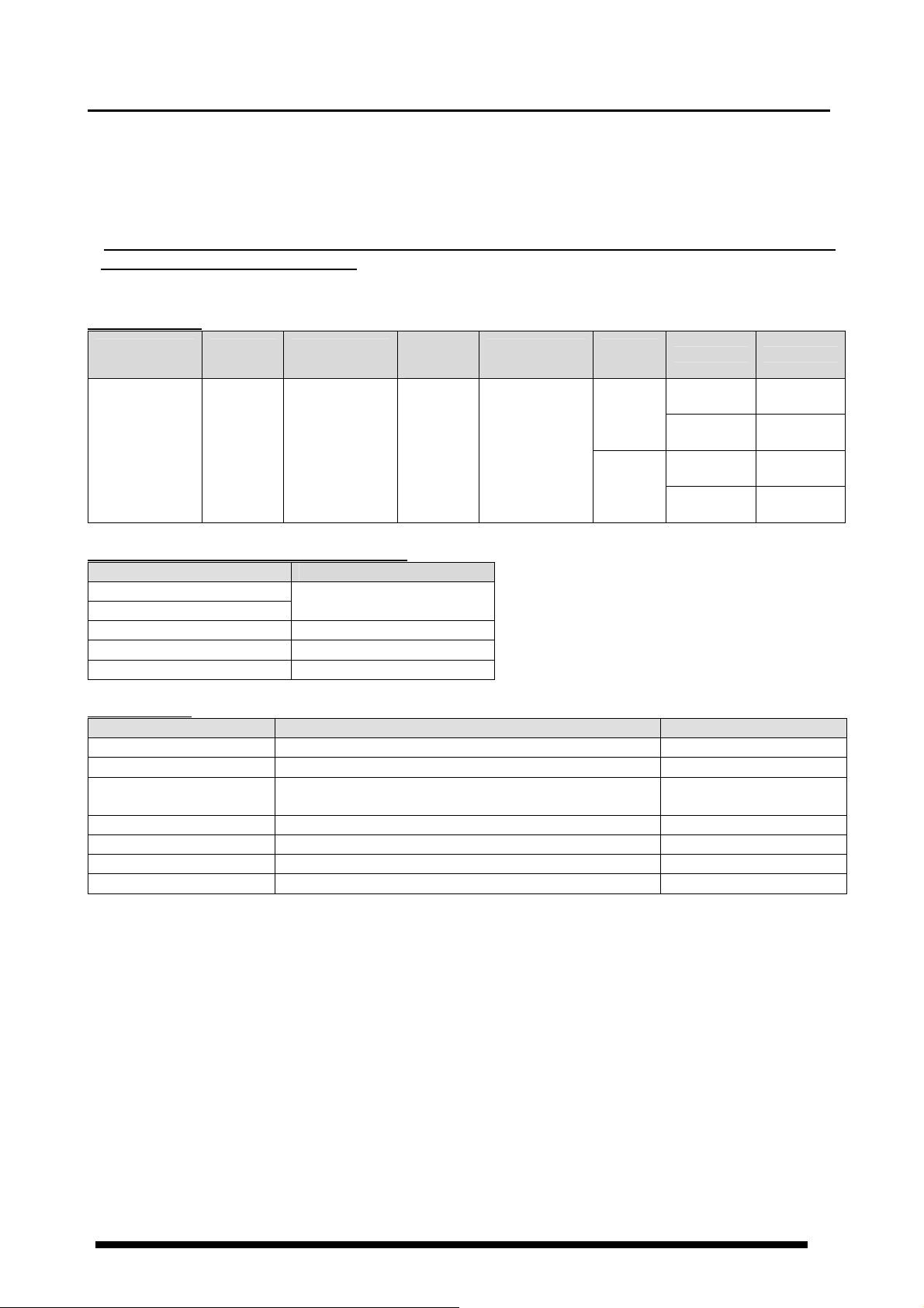
1-2 Unit’s Name and Part Numbers
1-2-1 Main unit
Phase and
Wire system
Power
Supply
Measured
voltage input
Measured
current
input
Current
transformer
Terminal
type
Protocol Model No
・Single-phase
two-wire
・Single-phase
three-wire
・Three-phase
three-wire
100-240V
AC
・100-120
/200-240V AC
・100-120V AC
・200-240V AC
5A
50A
100A
250A
400A
Dedicated CT
type
(5A/50A/100A/
250A/400A)
Screw
terminal
11-pin
MEWTOCOL
MODBUS
(RTU)
MEWTOCOL
MODBUS
(RTU)
AKW5111
AKW5112
AKW5211
AKW5212
1-2-2 Dedicated Current Transformer (CT)
Rated primary current Model No
5A
50A
AKW4801
100A AKW4802
250A AKW4803
400A AKW4804
1-2-3 Options
Product name Contents Model No
Mounting frame Used for mounting in a panel (supplied with a unit) AT8-DA4
Rubber gasket Used for mounting in a panel (supplied with a unit) ATC18002
Protective cover
Used for protecting a front display
(common to Timer/Counter)
AQM4803
DIN rail socket For 11-pin type(surface mounting) ATC180041
Rear terminal socket For 11-pin type (embedded mounting) AT78051
11P cap For 11-pin type (connectable directly with soldering) AT8-DP11
Mounting rail DIN rail terminal socket fixing rail AT8-DLA1
1

1-3 Measurement items
Item Unit Data range
Instantaneous electric power kW 0.00 to 9999.99
Integrated electrical energy
L1(CT1)-phase current
kWh
MWh
A
Current
Voltage
Electricity
charge
L2(CT2)-phase current
Voltage between 1-2 V 0.0 to 9999.9
Voltage between 2-3 V 0.0 to 9999.9
Yen JPY 0 to 999999
Dollars $ 0 to 9999.99
※
Euros EUR 0 to 9999.99
A
Yuan CNY 0 to 9999.99
Hour meter
ON-time h(Hour) 0.0 to 99999.9
OFF-time h(Hour) 0.0 to 99999.9
Pulse input Count 0 to 999999
※Eco-POWER METER is designed chiefly to manage saving energy.
It is neither intended nor can it be legally used for billing.
0.00 to 9999.99kWh to 10.00MWh to
9999.99MWh
9-digit display: 0.00 to 9999999.99 kWh
0.0~999.9
0.0~6000.0
0.0~999.9
0.0~6000.0
(MEWTOCOL type)
(MODBUS (RTU) type)
(MEWTOCOL type)
(MODBUS (RTU) type)
2
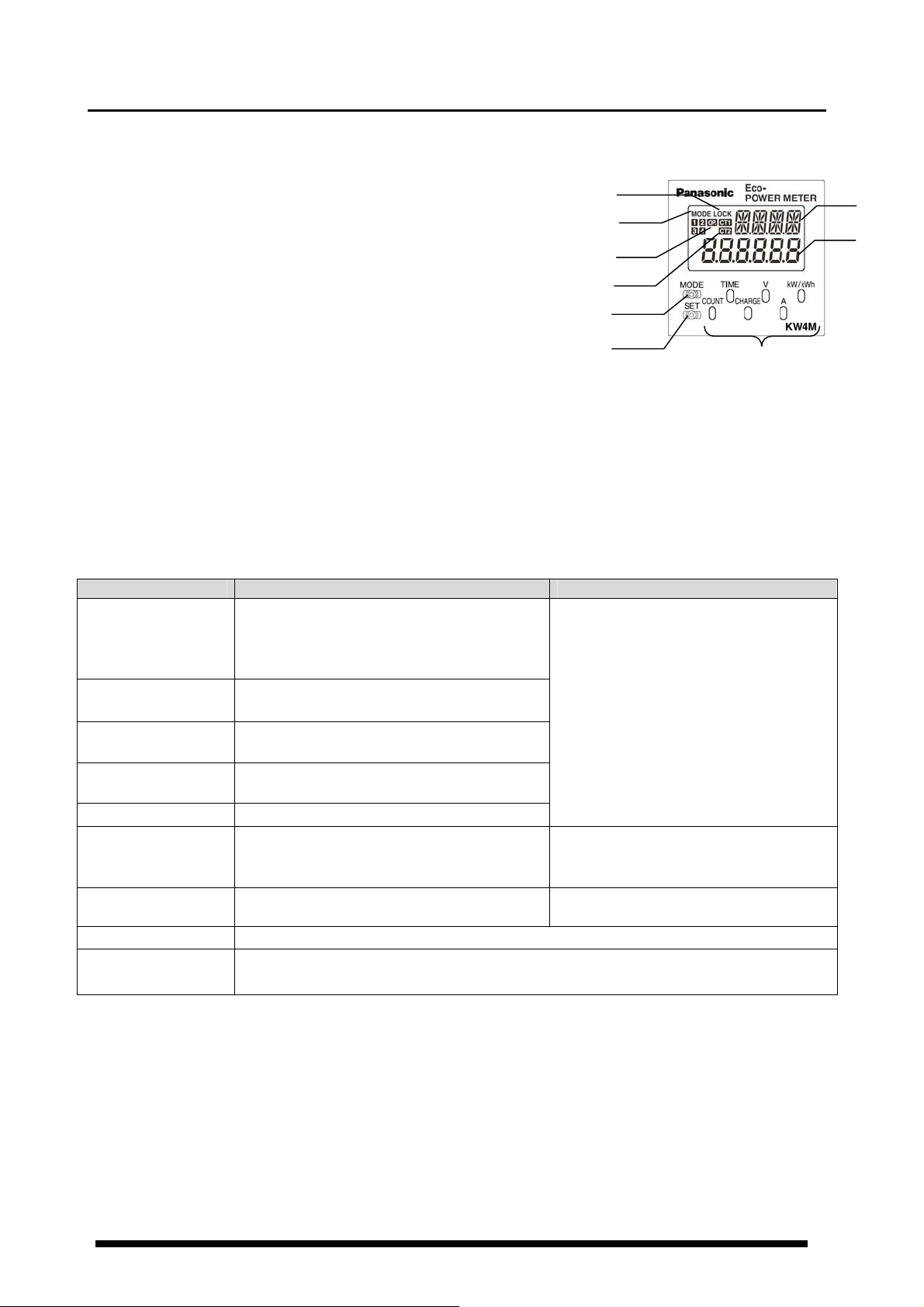
Chapter 2 Parts Name and Working
⑧
2-1 Parts Names
① Mode name display (16-segment)
② Lock indicator Light is on when locked.
③ Mode indicator Light is on when the mode is being set.
④ Output indicator Light is on when pulse is output.
⑤ CT direction notification Light is on when CT is connected
correctly and current flows.
⑥ Display for value selected (7-segment)
Instantaneous electric power,
Integrated electrical energy,
Current, Voltage, Electricity charge, Hour meter and Counter
⑦ MODE key Use to select mode
⑧ SET key Use to set each value entered
⑨ Select keys a) Change which value is displayed.
b) Make settings in a particular mode.
2-2 Select Keys’ Functions
POWER measurement PULSE measurement
・Instantaneous electric power →
<kW/kWh>
< A >
< V >
<CHARGE>
<TIME>
<COUNT> ---
<MODE>+<SET>
<MODE> Shift to each setting mode
<SET>
・(Continuous press) Display by 9-digit
(Integrated electric power)
L1(CT1)-phase current →
Voltage between 1 and 2 →
Electricity charge:
ON-time → OFF-time
Reset (Integrated electrical energy,
ON-time, OFF-time)
・Set each value entered
・(Continuous press) All keys locked. While in LOCK mode, releases LOCK mode
Integrated electrical energy
L2(CT2)-phase current
Between 2 and 3
JPY→ $ → EUR → CNY
・Count value → Preset value
(Continuous press at preset value display)
・
Reset (Count value)
②
③
④
⑤
⑦
⑨
---
Shift to preset value setting mode
①
⑥
3
Chapter 3 Display of each Value
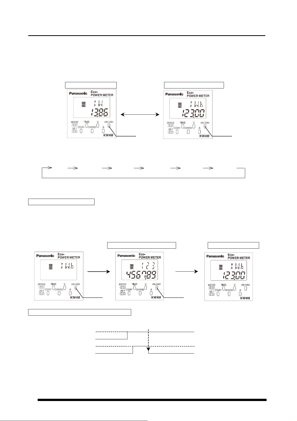
3-1 Instantaneous electric power / Integrated Electrical energy
・Press <kW/kWh>key to display the instantaneous electric power and integrated electrical energy.
・Press <kW/kWh>key to change the instantaneous electric power to integrated electrical energy.
*Displayed data is updated at every 1 second.
Instantaneous electric power(kW) → Integrated electrical energy(kWh)
Sample of 13.86kW Sample of 123.00kWh
・Integrated electrical energy is measured and displayed from 0.00kWh to 9999.99MWh.
・The decimal point and the unit are changed automatically.
kWh kWh kWh kWh MWh MWh
0.00 9999.99 10000.0 99999.9 100.00 9999.99
(After reaching the full scale (99999.9kWh), the value reverts to 0.00kWh but continues to measure.)
How to display with 9-digit
Integrated electrical energy can be displayed with 9-digit.
・Continuous press <kW/kWh> for about 2sec. or more at the instantaneous electric power or
integrated electrical energy display, “kWh” shows for about 0.5sec. and integrated electrical energy
with 9-digit is displayed.
Integrated electrical energy Instantaneous electric power
9-digit (kWh) (kW)
Sample of 1234567.89kWh Sample of 13.86kW
Shows for
about 0.5sec.
<kW/kWh> <kW/kWh>
How to reset the integrated electrical energy
・Press <MODE>key while pressing <SET>key makes integrated electrical energy clear.
Reset
<SET>
<MODE>
OFF
OFF
ON
ON
<kW/kWh>
<kW/kWh> <kW/kWh>
<kW/kWh>
4
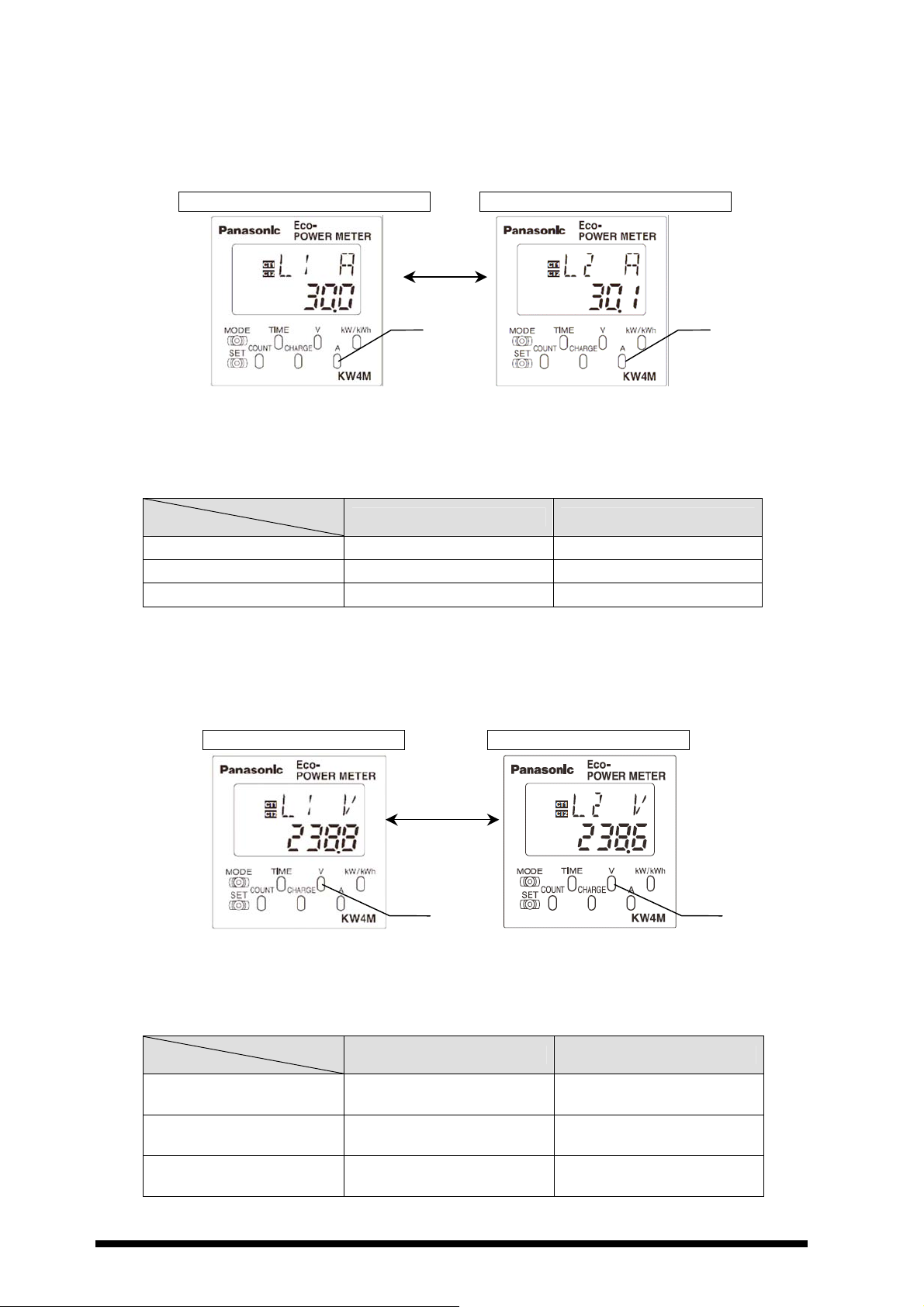
3-2 Current
・Press <A>key to display the current value of the load.
・Press <A>key to change L1(CT1)-phase current to L2(CT2)-phase current
*Displayed data is updated at every 1 second.
L1(CT1)-phase current (A) → L2(CT2)-phase current (A)
Sample of L1(CT1)-phase 30.0A Sample of L2(CT2)-phase 30.1A
<A>
< A > < A >
・When input current exceeds 150%F.S. at each range, 「- - - - - -」 will be displayed in
the lower line.
・Current measurement parts
Eco-POWER METER measures the current as below.
Display
System
L1(CT1)A L2(CT2)A
Single-phase two-wire 1(L1)-phase current -
Single-phase three-wire 1(R)-phase current 3(T)-phase current
Three-phase three-wire 1(R)-phase current 3(T)-phase current
3-3 Voltage
・Press <V>key to display the voltage value of the load.
・Press <V>key to change voltage between 1 and 2(V) to 2 and 3(V).
*Displayed data is updated at every 1 second.
Voltage between 1 and 2(V) → Voltage between 2 and 3(V)
Sample display of 238.8V Sample display of 238.6V
・When input voltage exceeds 150%F.S. at each range, 「- - - - - -」 will be displayed in
the lower line.
・Voltage measurement parts
Eco-POWER METER measures the voltage as below.
Display
System
Single-phase two-wire
Single-phase three-wire
Three-phase three-wire
Voltage between 1 and 2
Voltage between 1 and 2
Voltage between 1 and 2
(Between R and S line)
<V>
< V > < V >
L1V L2V
(R-phase)
-
Voltage between 2 and 3
(R-phase)
(T-phase)
Voltage between 2 and 3
(Between S and T line)
5
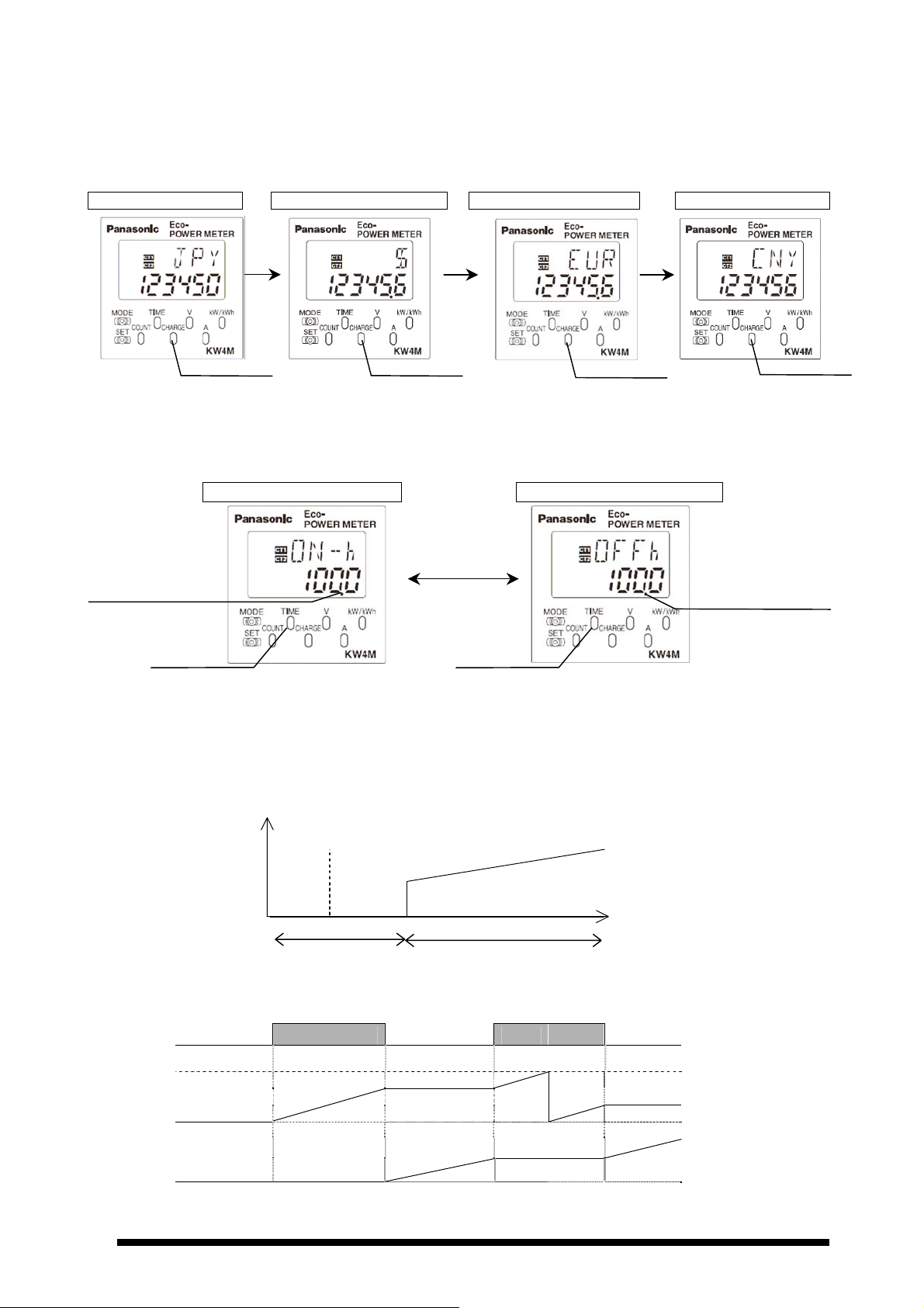
3-4 Electricity Charge
It displays the standard electricity charge for the integrated electrical energy.
・Press <CHARGE>key to display the electricity charge.
・At electricity charge display, press <CHARGE>key to change between JPY, $,EUR and CNY.
Yen → Dollars → Euros → Yuan
Sample of 123450 yen Sample of 12345.6 dollars Sample of 12345.6 euros Sample of 123456 yuan
<CHARGE> <CHARGE>
<CHARGE>
<CHARGE>
3-5 Hour Meter
・Press <TIME> key to display the load ON-time or load OFF-time measured by CT1.
・Press <TIME> key to change the load ON-time to load OFF-time.
ON-time (h) → OFF-time (h)
Sample of ON-time 100.0 h Sample of OFF-time 100.0 h
Blinking the decimal point
during measurement of
ON-time
<TIME>
*When load current is under the setting current for time measurement(HM-A), it measures as
OFF-time. When load current is exceeded to the setting current for time measurement(HM-A), it
measures as ON-time. Current for time measurement (HM-A) is set to under cutoff current (CUTA),
all current is measured as OFF-time.
*Current flow of CT1
Load ON-time
<TIME>
<TIME>
Blinking the decimal
point during
measurement of
0 HM-A CUTA
[h]
Ratio of load current [%]
Measured as OFF-h Measured as ON-h
*After reaching the full scale (99999.9h), the value reverts to 0.0h but continues to measure.
ON ON
CT Detection OFF OFF
Full scale
ON-time
OFF-time
6
How to Reset ON/OFF-time
・Press <MODE>key while pressing <SET>key makes ON / OFF-time clear.
Reset
<SET>
<MODE>
OFF
OFF
ON
ON
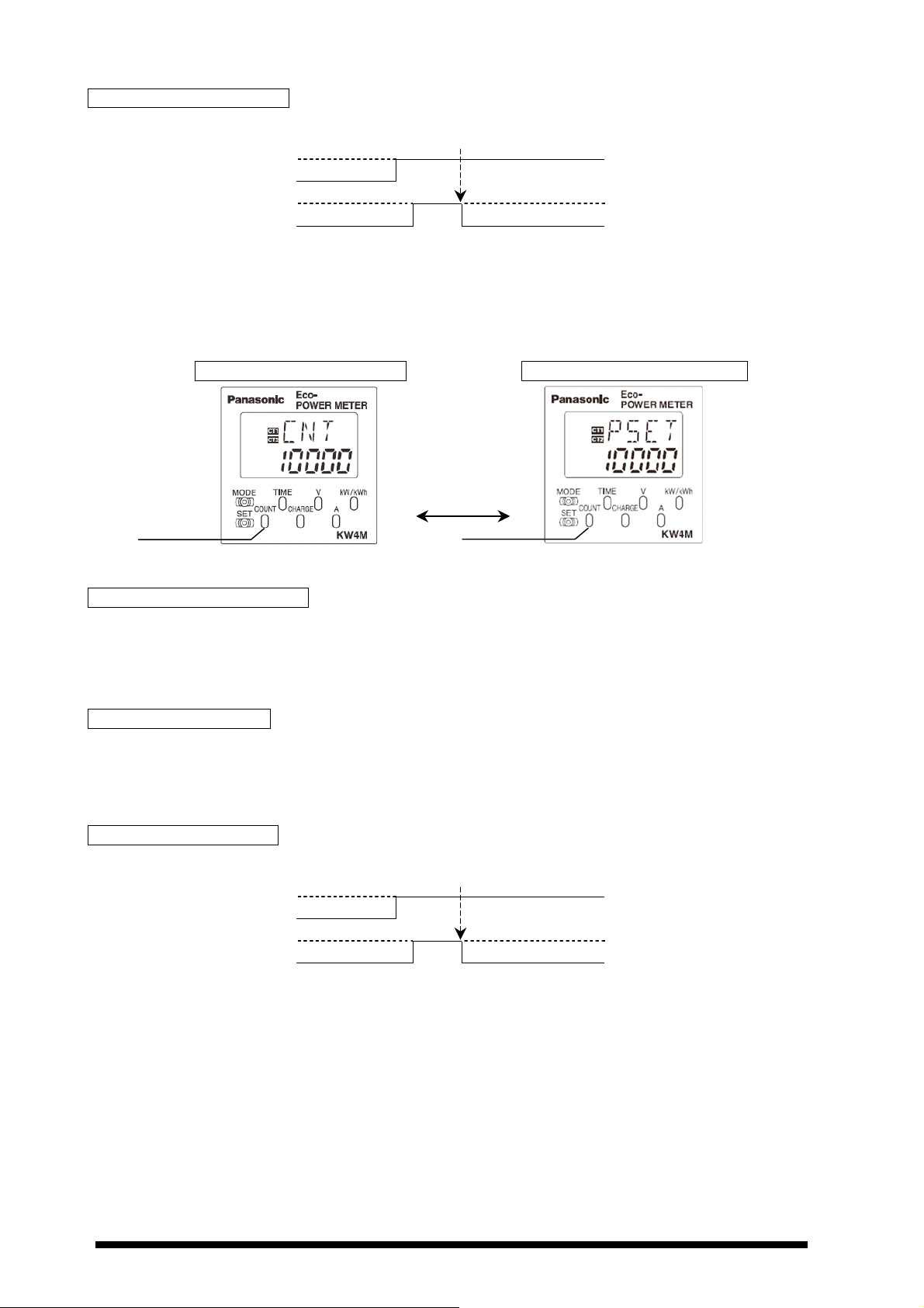
3-6 Count Value / Preset Value
It displays present count value (pulse input value) and preset value.
・Press <COUNT> key to display count value (pulse input value).
・Press <COUNT> key to change count value to preset value.
Count value(COUNT) → Preset value(COUNT)
Sample of count value:10000 Sample of preset value:10000
<COUNT>
How to Enter the Preset Value
・Press <COUNT> continuously for about 3sec. at preset value display, “PSET” is blinking.
・Enter a preset value using <kW/kWh>,< A >, < V >, <CHARGE>, <TIME> and <COUNT>.
・Press <SET> to set the entered value. “PSET” stops blinking.
Position of Decimal Point
・The position of decimal point for count value and preset value is decided according to the setting at
‘Pre-scale setting mode’.
Ex) When preset value set to 0.01, the decimal point is fixed the last 2 digit for count value and preset
value.
How to Reset Count value
・Press <MODE>key while pressing <SET>key makes count value clear.
Reset
<SET>
<MODE>
OFF
OFF
ON
ON
<COUNT>
<COUNT>
7
 Loading...