

Panasonic JU-455-5 Service Manual
ORDER NO. M SD850902
900
Flexible Disk Storage Drive
,,",U-455-5
Panasonic
Matsushita
Industrial Co., Ltd.
Memory
3-1, 4-chom
oku-k
Koh
Communication
Systems Division
e,
Tsunashima-Higashi
u, Yokohama
223
JAPAN
PA
RT
I
INTR
1.
2.
3.
4.
5.
••
7.
••
g.
10.
ODUCTION "-
MODELS
SPECIAL
OUTLINE OF
DIAGNOSTIC
5.1 Error Symptom Recognition
5.2
5.3
5.4
5.5
5.6 Comp
TROU8LE ANALYSIS
6.1 Tr
6.2 Trouble Shooting .. .
6.3 Trouble
PR
M EASUREMENT
AD
9.1 Mo
9.2
9.3 Head
9.4
9.5
9.6
9
9.S
9.9
9.10
9.
PANA SONIC ALIGNMENT
AND MDOOE L NUM BE
TOOlS
50
ft
Write
Read
Seek.
ouble
EVENTIVE MAINTENANCE ..
JUST
MEN
tor
Write
Outp
Radial Alig
Azimuth
.7
Inde~
Tr"c~
Limiter Ver
limiter
11
Asymmetry V
..•.••.••...••..•••.••.....••.•..•.......
·······················
MAINT
ENANCE .•.••.
PROCEDURES ...................................
Error
Detection
Effor .
Error
.......
Effor
at
ibili
ty
AnalysIs Procedure ..
Analy~is
I
TEMS FOR EACH
TS AND
Speed
Protect Verification
Output
ut Modulation Verif
nment Adjustment ....
Verifi
Burst Veri
00 Sensor Adjus
ificatio
Adjustment (3.S·inch) .
CONTENTS
...
•...
.•••
••...••..•....•...
RS
.....................................................
····· ·····
•.•..••
and Correcti
...............................................................................................................
...
...
.............................
....
...
...
.... . .......................
Error ..
...
..............................................................................................................
VERIFICATIONS ......
Adjustment
Veri fication
cation ..
ficatio
erific
..........
...
............
T
able
' ..
..........
.............................................
MODEL ...
and V
icati
.......
ns
............
tme
nt
ns
(5.25·inch)
ations
.....
DISKETTE
················
.•••....•...••...•...••..•..•••...•....•
......
......
.........................................
on
.......
...
....................................
....................
.....
........
... .
........
...................................
..............
erif
ication
......................
.......
......
...........................
on ........................................................................
.........
......
.....
.......
....
.... · ..
....................
....
.............
......
··
......
....
·...................
. .....
.........
......................
.........
.....
..........................................
..• ..
...
...............
....
.......
...........
.........................................
.......
-..
........................
....
......
......
....
...
...........
(Inde~
Period) .
....
............
......
..... ........
...
.........
...... .
···
..
....
····
··
..................
.........
....
.........................................................
...
......... ......
.....
.....
...............................
........
.. . .......
...
............ .....
...
............
..........
........
...
..........................................
....
.............................
....................................
............................................
..
................
.........•. .
...
.•.
.....
....
....
........
..........
.......
...............................
...
.....................
......
........
........................................
.............
...
...
........
......................................
................................................
..
........
. .......
.... . ....
...•
.. •••..
.............
................
...........
.
............
........
.....
............
.......
....
......
..............................
....
........
........
......
....
....
......
.....
.........
.......
... . .
...........................
...
......................
••....•.••.•.••.•.
...................
.......
......
.........
...
....
...
...................
.
.....
....................
.............
.........
.................
...
...
...........
.......
. .
.
.....
......
....
...
..........
. ..
...
.....
..
.
...
.........
............
..
.
......
....
....
....
...
..... ..
....
...
....
Page
.
..
.
..
.
..
. .
..
.
..
.
..
.
..
.
.
.
.
2
2
2
.
2
3
3
3
3
3
3
4
.
5
5
.
•
7
7
7
7
•
.
•
10
.
ID
11
.
11
11
11
12
•
•
PAR
T!!
11
.
REMOVALS AND IN STALLATIONS
1
1.1 PCB
1.2
1
11.3
11.4
11
.5 Clamp Assemb ly Removal and Installation
11
.6
11
.7
I I .S Stepper
1
1.9 COlIrriage
11.
10 Drive
1.11
,
12.
TE
13. EXPLODED
14. REPlACEMENT PARTS LIST
15.
16. SCHEMATIC DIAGRAM ........
17.
lB
ST POINTS
REPLACEMENT
CIRCUIT
. BLO
CK DIAGRAM
Removal and In5tallatlo(\.
Front
plate
Trac
Collect Assembly Removal, Installation and
Write Protect
Cartridge Guide Assembly R
LED Assembly Remova l and Installation
BOARD
Removal and Installation
k.
00 Assembly Removal and Installat;on·
Sensorllnde~
Motor
Assembly RemOval and Installation
Arm
Motor
....
ViEW·
Assembly Removal and Installation.
Removal and Installation
.....................
..
···
.. · .... ···
PARTS LI
ST
...............................................................
...
..............................
.. · ....
···
.... · .. · ............ · ................
...................
...........................
Detector
emoval and Installation
.......
......
··· ... · ....
..........................
OF PCS
............
.............
Assembly
......................................................
........................................................
............................
.............
... ...
...................................
...
...............
.. · ....
.. · .. · .....
Adjustment
...................................................
Removal and Installati
.........
...........
.............
.........
.............
...........
..........
...............
...
......................................
...
....
....
..........
.........
...
..........
...
.............................
.. · .. · .........................
......
......
.........
.....
...................................................
.....
............
...
............
...........
...
....
.....
..........
.....
..........
............
....
..............
......
.......
.............
..............................
......
on ....
................
.........................................
..........................
.....
......
.....
..................
....
....................
..........
.............
.......
.
.................................
............
.......
....
.....
.....
.................
...
...........
....
.•.........
..........................
......
.......
.................
.....
.....................
.....
.................
....
.......
.........................
........ ................
.............
...
....
...
.......
..
.........
.....
.....
........
.....
.... ..
..... ........
......
.....
.....
•
.
13
. .
13
.
13
.
..
..
..
..
..
13
14
14
15
.
15
.
16
.
16
.
17
17
.
18
..
..
20
"
21
22
23
.
24
•
t
•
PART.
1.
INTRODUCTION
This
analysis
Pa
work
service
rt
I en com
on
lm
the
I
manual
d Pa
passes
FOD.
consists of two parts,
rt
II
disasse
mainte nance in
Part
I covering mainten<lnce de
mbl
y and reassembly procedures
nruct
ions
for all
parts
FDD
models. Refer to
list,
and
PCB circuits.
scrip
tion, adjustment procedures, and trouble
the
app
lic
ilb
le items,
lind
perform
maintenance
r
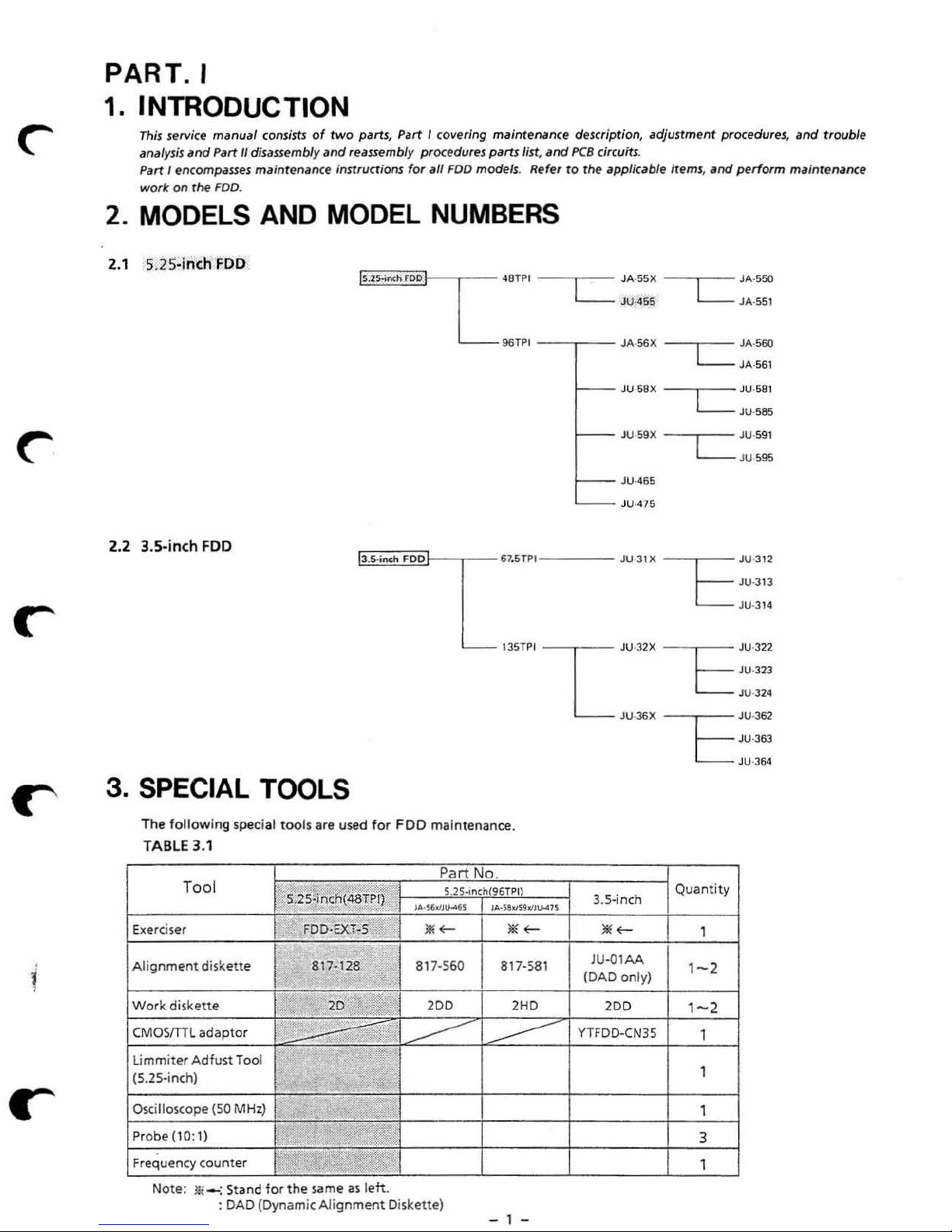
2. MODELS AND MODEL
2.1 5.25·inch
2.2 3.S-inch
FDD
FOD
~'2'I
..
~~~'~'~'~'J--,-
l .
5-i
nch
FOO
NUMBERS
-
48TPI --'L--
96TPI
--
61
.STPI -
135TPI I JU':,2X
,...
--
L
JA
·SSX
JU.455
__ JA.56X
JU·ssx
JU ·59)( -
- -JU·31)(
Ju.J6x
JA ·
550
LJA
---,
--
L-
- -CL-
--,--
L-
-r=
-r=
-r=
-JU.
.
551
JA·
560
JA•561
581
JU·S85
JU ·591
JU.595
JU·312
JU-313
JU·]
JU.322
JU·323
JU-
J24
NJ6'
JU-363
JU-364
14
3. SPECIAL TOOLS
The following
TABLE 3.1
To
Exerciser
Alignment
ol
disk
ett
spe
e
cial
too
ls
are used for
S.25
ti
FDD·Ex:r~
817-128
I
Wo
rk diskette
CMOSm
Li
(S.25-inc
r
Osci
Pr
Frequency counter
L adap
mmiter
Adfust
l-l)
lloscope (
obe (10: 1)
Note:
tor
Tool
SO
MHz)
*"
_: Stand
: DAD (Dynam
for
.
,
.
.,'
" .
the
-
sam
ic
Alignmen
FDO
n~ht~T
P
·
S
2D,
~'.~,
~
.,
'.·'6.'IU"U
817-560
AI'"
----
;;.
,
,
;;$l
"f'"
e as
lett.
t Diskette)
mai
nte
nance.
Part No.
5.2S.,nch(95TPI)
,
.. ·sa",.
..
~
817·581
I
2DD 2
----
- 1 -
,.
<1,
~
HD
....
"
3.S-inch
"'~
JU
.(I1
AA
(DAD only
2DD
YTFDD-CN35
)
Quantity
1
1
-2
1-2
1
1
1
3
1
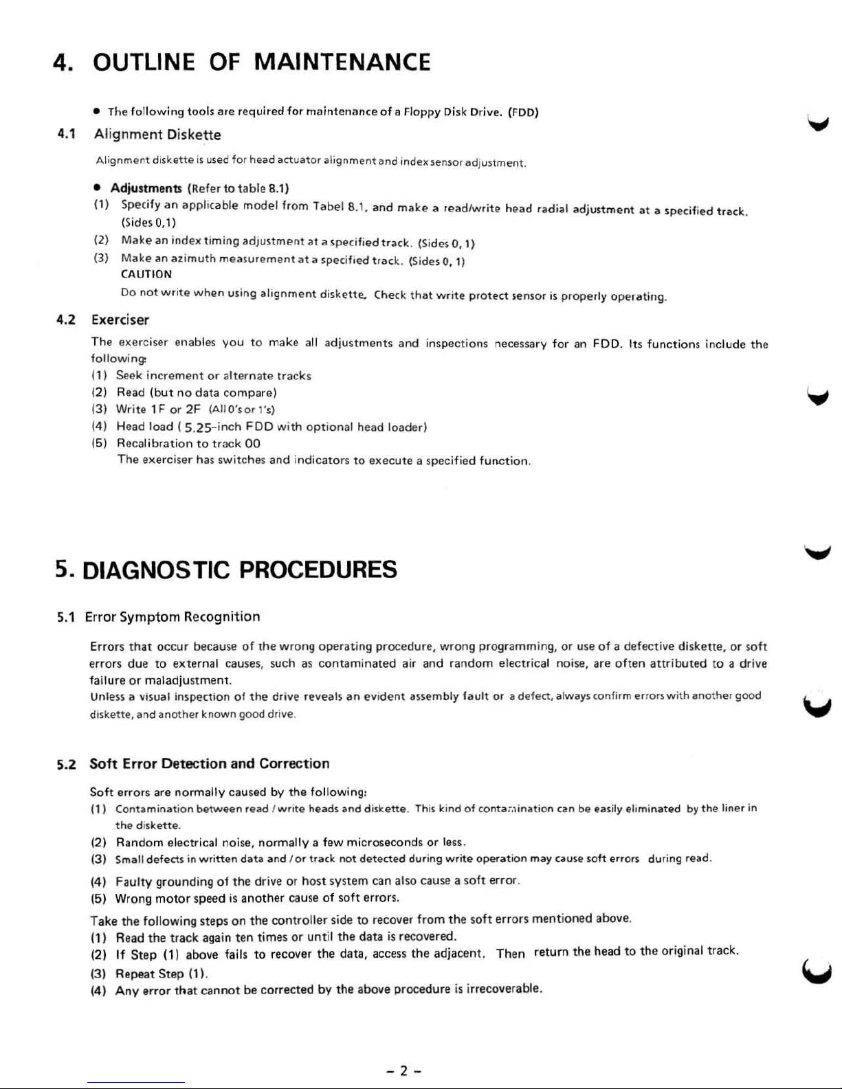
4. OUTLINE
• The
4.1 A
following
lign
ment Diskett
tools ate required
OF
e
MAINTENANCE
for
maintenance
of
a Floppy Di
sk
Dri
ve.
(FOO)
Alignment
•
Ad;tiume
(1)
Specify
(SidesQ,l)
(2)
Make
Make
(3)
CAUTION
Do
not
4.2 Exerciser
The
exerciser enables
follow
ing:
(1) Seek
(2) Read
(3) Write 1 F
(4) Head load
(5) Recalibration
The exerciser has switches
diskette
nts (Refer to
an
appIJc
an
iodell
iH
I
azimuth
write
when
increment
(but
no data
or
2F
(S.2S-inch
is
used
for nead
table 8.1)
able mode l from
timing
adjustment
measurement
using
alignment
you
to
or
alternate
compare)
(AIIO'sor "
FDD
to
track
00
actuator
make
ali
gnment
label
at
a specified Irack. (Sides
at
a specifi
diskette.. Check
and index sensor adjustment .
8.1.
CInd
make a readlwrite head radial adjustment at a specified tracle.
O.
ed
tracl
e (Sides 0, 1)
that
write
1)
protect
sens
or
is
properly
operating
.
all adjustments and inspections necessary for an FDD. Its functions include the
tracks
s)
with
and
indicators
optional
head
to
execute
loader)
a specified
function
.
5.
DIAGNOSTIC PROCEDURES
5.1 Error Symptom R
Errors
that occur
erro
rs
due
or
failure
Unless a visual inspection of
diskette, and another known good dri
5.2
Soft
Soft errors are normally caused by
(1) Contamination between read
(2)
(3)
(4)
(5) Wrong
Take the
(1) Read
(2)
(3) Repe
(4) Any
maladjus
E
rror Detection and Correctio
the diskett
Random electric
Small
defects
F
aulty
following steps on
the
If
Step
at
error
e<o
gnition
because
to
external
tment.
e.
al noise, normally a f
in
wri
tten
grounding
of
motor speed
track again
(1) above fails
Step
(11
.
that
cannot
of
the wrong
causes, such
the
dri
...
...
e.
I write heads and diskette.
data and
the
dr
....
e or
is
another
the
controller
ten
tim
es
to
recover
be
corrected
operating
as
contaminated
e reveals
n
th
e following:
ew microseco
l or
tfaclr.
host
system can also cause a
cause
of
soft errors.
side
or
unt
il the
the
by the above
procedure,
air and
an
evident
auembly
This
nds
not detected duri
to
recover from
data
is
recovered.
data
, access the
procedure
wrong
programming,
random
fault or
electrical noise, are
II
defect, always confirm errors with another good
or
use
of
a defective diskette, or
often
kind of cont.}:,lination can be easily ehminated
or
less.
ng
write operation
soft erro
the
soft
adjacent.
may cause roft errors during read.
r.
errors
ment
ioned above.
Then
return
the
head
to
the
is irrecoverable.
attributed
by
origi n
al
to
a drive
the liner
track.
soft
in
- 2 -
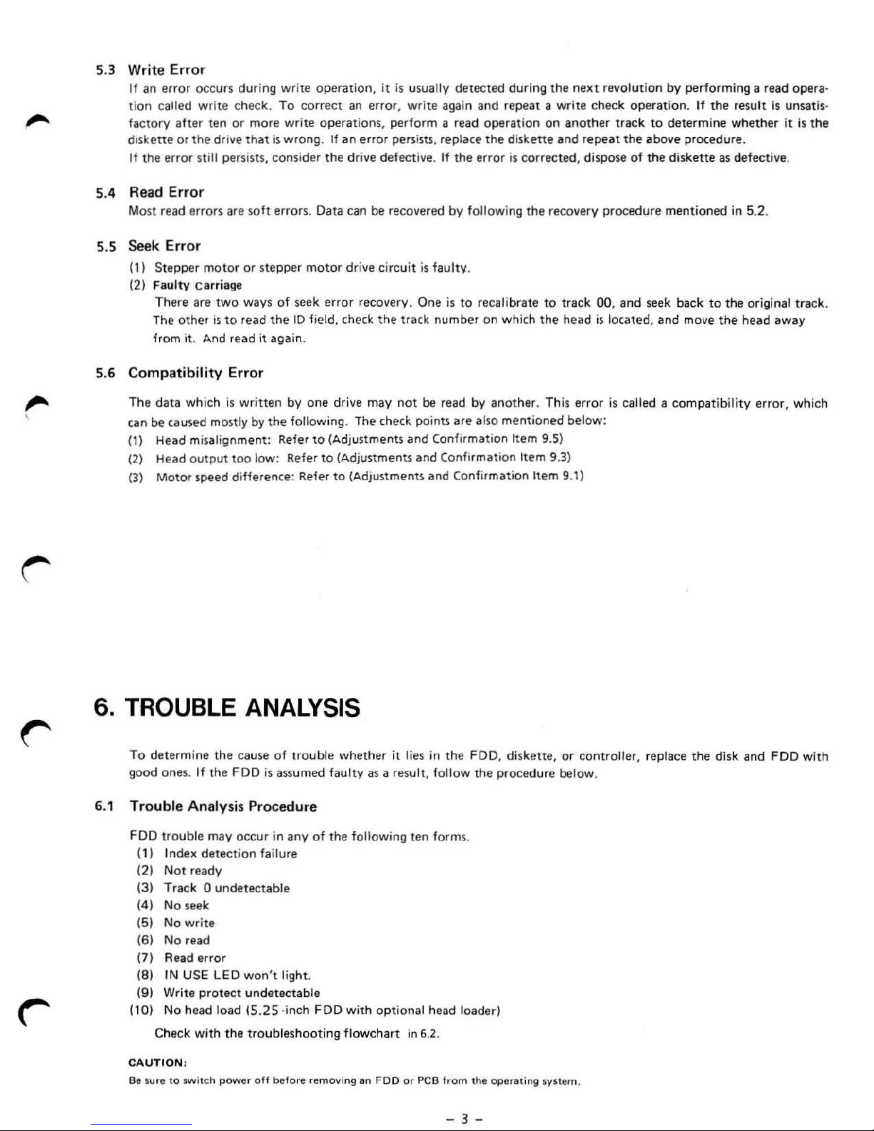
5.3
Write Error
If
an
error
occurs
dur
ing write
ti
on
called wr i
factory
diskette or
If
after
the error
te
check.
ten or more write operations, perform a read ope r
the drive
still persists, consider
that
5.4 Read Error
Most read errors are soft errors. Data
5.5 Seek Error
(1)
Stepper
(2) Faulty carriage
There are
The
from it. And read
other
motor
two
is
to rea d
or
stepper
ways
it
5.6 Compatibility Error
The
data
which
is
written
c.,used mOitly by
can be
(1) Head
(2) Head o
(3) Motor
mi
salignment: Refer
utp
ut
too
low: Refer
speed
difference: Refer
operation,
To
correct
is
wrong .
of
the
again.
by
the
If
the dri
motor dri
seek
error
10 field, check
one
drive may
fonowing. The check points
to
(Adjustments and Confirmation I
to (Adjustments
to (Adjus
it
is
an
error
, write again
an
error
persists, rep lace
ve
defective. If
can be recovered
ve
cir
cuit
recovery. One
the
not
tments
usually
track number on wh i
detected
the
by foll
is
faulty.
is
to
be
read
are .,Iso mentioned
and
COnfi
and Confirmation Item 9.1)
during the
and repeat
ation
the disk
error
is
owi ng the recovery procedu re mentioned in 5.2.
recalibrate
by
another
tem
rmation Item 9.3)
next
a write check
on another track
ette
and
repeat
corrected
ch
, dispose of the di
to
track 00,
the
head
. Th
is
error
below:
9.5)
revoluti
and
is
located,
is
called a
on
by perform ing a read opera·
operation.
to
determine
the
above
seek back
and
If
the
result
whether
procedure.
skette
as
defective.
to
the
move
the
head
compatibility
is
unsatis-
it is
the
original track.
away
error, which
6. TROUBLE ANALYSIS
To
determ
ine
the
cause
of
troub
good
ones.
If
the FDD
6.1 Trouble Analy
FDD
troub
le may
(1 ) Index
(2)
(3
) Track 0 unde
(4)
(5) No write
(6 ) No
(7) Read err
(8)
(9) Write
(10) No
Check
CAUTION :
Be sure to switch
detection
Not ready
No seek
read
IN USE
protect
head
with
or
LED
load
power off before r
is
assumed faulty
sis
Procedure
occur
in any
failure
te
cta
ble
won
't light.
undetectable
15.25
·inch FDD
the
tro
ubl eshooting flowchart
le
whether
of
the following ten forms.
with
emoving
it lies in the
as a re
sult, follow the proce
opt
ional head loader)
in
an
FOO
or
PCB
6.2.
FDD
, diskette,
from the opera
- 3 -
dur
ting
or
e below .
svnem.
contro
ller, replace
the
disk and FDD wi
th
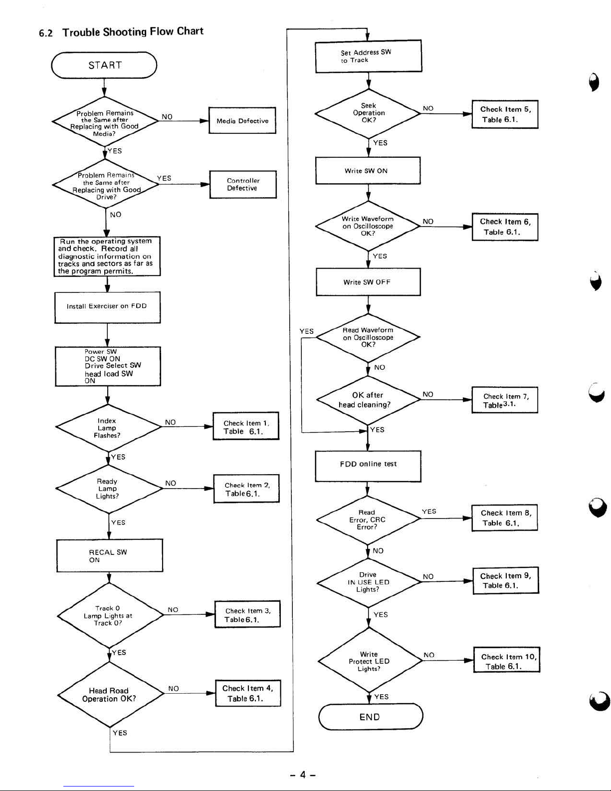
6.2 Trouble Shooting Flow Chart
ST
ART
Set
10
Addru.
Track
SW
- 4 -
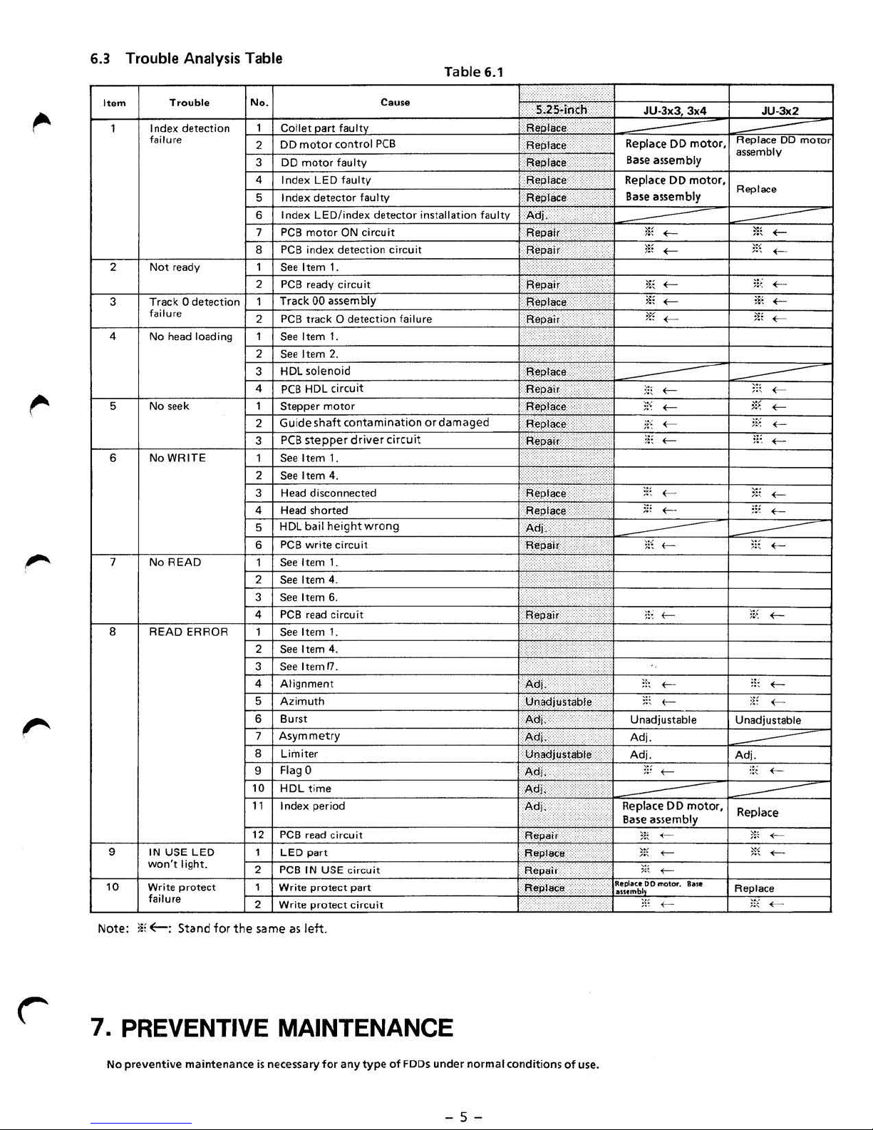
6.3
Trouble
Item
Index
1
fai
Not
2
3 Track 0
failure
4
Na
5
Na
NoWR
6
7 No READ
READ ERROR
•
,
IN USE
won't
Write p rotect
'0
failure
Note:
ii, (-: Sta
Analysis Table
N
Trouble
detection
lure
ready
detection
head loading 1 See Item 1,
seek
IT E
o.
1 Collet
DO
2
3
4
5
6 Index LED li ndex det!!Ctor installation faultv
7
•
1 See I
2
1
2
2
3
4
,
2
3
,
2 See Item
3 Head disconnected R.epface
4
5
6
,
2
3 See Item 6.
4
,
2
3 See I
4 Alignment Adj.
5
6
7
•
,
10
motor
DO
motor
Index LEO faultv
Index
detector
PCB
motor
PCB
index
tem
PCB
ready circuit
Track 00
PC
B Irack 0
Hem
See
HOL
solenoid
PCB
HDL
Stepper
Guide
shaft
PCB
stepper dri
See Item 1.
Hlilad
shorted Replace '
HDL
bail
PCB
write
See Item 1.
Item 4 .
See
PCB
read circuit Rep'air
See Item 1.
See Item 4.
temO"
Azimuth
Burst
Asymmetry
Limiter
Fl
agO
HOl
time
Index period
"
12
PCB
lEO
light.
nd
for
the
,
2
,
2
same
LEO
PCB
Write
Wr
ite
as
read circuit
part
IN
protect
protect
lett.
Table 6.1
Cause
art
fault
(Ontlol PCB
faulty
faulty
ON circuit R'epalr
detection
1. '?
a~5embl
2,
tircuit
motor
(Ontamination
4.
height
circuit
y
detection
ver
wrong
circuit
failure
circuit
or
damaged
S.2S·j'
lace,
R.
~
~eploce
~liIpllM':e
f':Il!'pl<IC!,::\:
laCe::,
ReP
Adj,
Repair
Rep~ir
:',
.AeplltC!I
Rapai,
N,.'CA?
:::
ReP
t~e
Repair
Rep
hke
Repix.e:::)
'Repai'r rh<W
i
·'
\iF'
Adj
:=:
Aepai~
..
...
.
.,.
....
.
'I' \ .•.•
.
USE circuit Repair
part
circuit
,
,Uiladju
Ad(
AOj
. Adj.
UQadjuSfable
'Adj,
p,dj
,
~dj,;
,
Repair'
fI"plece
fI~l8(;e
.'~
ndi
,
: :
:~:
:
:,:,:::
,
, ,
...
.
'.'
).
:(
""''-::~
••
••
'"
.,.,
,
::'
:
'
,
,.
,,'
.
..
'
,,&
,
..
..
....
uable
,'
?
:;
'"
•...
".:',.
':""
.-.~
.i
.,
JU-3x3
Replace
Base
Replace
Base
DO
assembly
DO moto
assembly
*,
-
;i,
-
*,
-
!!i
-
<
*
>;(
-
)"
-
ii
~
<
;-"
-
::
;
,::
-
-
:,s
:
<
1'
\
-
' .
;:;
-
,i
;
-
Unadjustable
Adj.
>;
:
-
Replace
Base ;5Ssembly
R.plKODD_.
....
DO
:;:
<
m
-
,,
:
-
'"
:I:
-
,..
motor
motor,
...
Rep lace
.
assemblV
r.
Replace
*:
>;,
,;
if
:!,
,
;;;
)"
::'
3;:
:!'
;,~
'"
;;,
;::
UnlKljUSlable
Adj.
'"
Replace
;-So
~
Replace
,,~
JU-
,'
.
..
.
3x2
00
-
-
-
-
-
<
-
-
<
<-
-
-
-
-
<
<
-
-
-
motor
7. PREVENTIVE MAINTENANCE
No preventive maint
enan
ce
is n
ecessary
far
any
type
of
FODs
und
- 5 -
er
normal
conditio
ns
of
use.
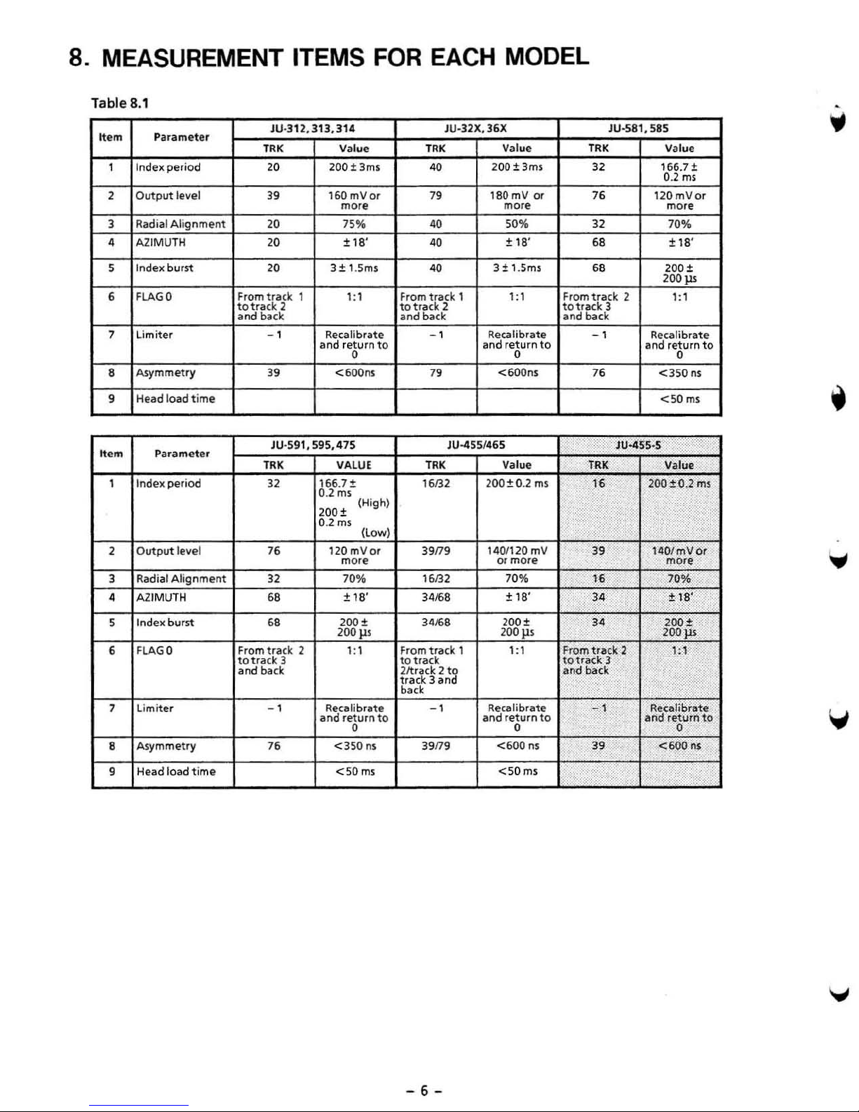
8. MEASUREMENT ITEMS
Table 8.1
JU
-312,
1
2
JU
-591, 595,
313,314
Value
200t3ms
16OmVor
more
75"
± 1
3±1.5ms
' ;1
Recalibrate
and return
<6oons
475
VALUE
166.7;!;
0.2
ms
200t
0.2
ms
120 m
more
70%
±
8'
0
(High)
18'
••
m P
Index
1
Output
2
,
Radial
4
AZIMUTH
Index
5
FLAG
6
7
limiter
Asym
•
Head load t ime
•
• • m
1
2
,
4 AZIMUTH
Parameter
IndelC
Output
Radial
aramete
r
period
level
Alignment
burst
0 From
metry
period
level 76
Alignment
totTack
and
TRK
20
39
20
20
20
track
back
-1
,.
TRK
32
32
6.
FOR
to
(Low)
llo(
EACH MODEL
JU·32X,36X JU-581,S85
T
RK
40
7'
40
40
40
From
track
totra,k
and
1
2 totTack 3
back.
-1
7.
JU-4 5S/465
TR
K Value
16132
39n9
16132
311/68
Value
200 ±
180mVor
more more
50% 32
±
18
3±1.5ms
1:
1 From
Recalibrate - 1
and
return
0
<600ns
200±
O.2
1401120m
or more
70%
t
18'
3ms
'
ms
to
V
TR
K Val
32 166.7
76
68
68 200 t
track
and
back
76
JU-455·5
TRK
16
....
,
,.
"
34
2
and
ue
;!;
0.2
m5
120mVor
70%
±
18
'
200
III
1: 1
Recalibrate
return
0
<3
50
ns
<5
0m5
Va
lue
200±0.1
c)
•
140/mllor
more
70%
± 18'
to
ms
Index
5
6
FLAG
7 Limite r
Asymmetry
•
Head
•
burn
0
load
2
and
200t
200p.s
1: 1
Recalibrate
return
0
<350
ns
<50
m$
to
6.
From
track
to
track
back
-1
76
3
and
t i
me
311/68
From
track
to
track
2ltrack 2 to
track 3 and
back
-1
39n9
200t
200 }ls
1 1: 1 From
Recalibrate
and
return
0
<600
<50ms
n$
to
totrack
and
34
track
back
'C<.
-1
3.
i"
200
t
200jU
,;
2
3
1
Recalibrate
arid
return
0
<600",
.
...
to
-
6-
9. ADJUSTMENTS AND VERIFICATIONS
9.1 Motor Speed
(1
} Insert a diskette, run the
model .
(2)
Step
(3) Connect
. 5.25,-inch : TP7
3.5·inch: IX
(4) Check that the fr
(5)
Adjuument
5.25 -
3.5-inch
Adjustment
to
the specified tra ck.
a frequen
inch
: Turn the spe
: No adju s
cy co
equency
tment
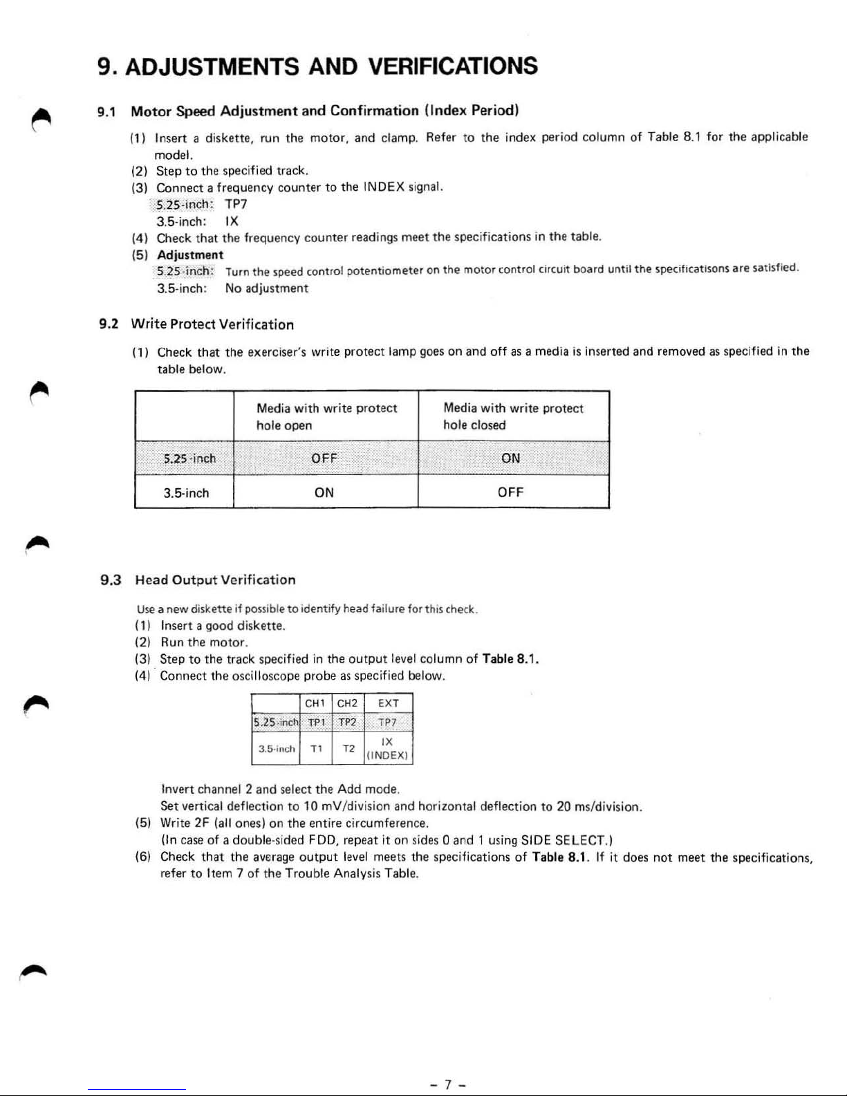
9.2 Write Protect Verification
(1)
Check that the exerciser's write protect lamp go
table
below.
Media wi
hole
S.2.S-inch OFF-
3.5·inch ON
and Confirmation !Index Period)
motor, and
unter
to
counter read ings
ed
contro
th
write prot
ope
n hole clos
the
INDE
l po
tentiometer
damp
X signal.
meet
ect
, Ref
er
to
the
specifications in the table.
on
the
motor control circuit bo
es
on and
Media wi
the inde
oft
as
th
write prote
ed
ON
OFF
x period
column
ard
unt
of
Table 8.1 for the applicable
il
the
spedfic:at
isons
are
satisfied.
a media is inserted and removed as specified
ct
in
the
9.3
Head
Output
Use
a new diske
(1) Insert a
(2)
Run the
(3)
Step
to
(4) · C
onnect the oscillos
Invert
Set
vertical deflection
(5) Write
(
In
2F (all
caseot
(6) Check
refer
to
Verification
tte
i1
good
motor
the tra
channe
possible
diskette.
.
ck specified
l 2
ones)
cope
S.2S·inc
3.5·"lCh
and
select the
on
to identity
in
the o
probe
C
H1
h l
Pl
T1
to
10
mV/div isi
the
entire
a double·sided FDD, repeat it
that
the avtrage
Item 7
of
out
the
Trouble Analy
put
head
failure
fo
r
thi~
check.
utpu
t leve l
as
specified below .
CH2 EXT
TP2
TP7
T2
"
UN
DE
X}
Add
mode.
on
and hor izontal
column
of Table 8.1 .
circumference.
on
sides 0 and 1 using SIDE SELECT.)
level meets the specificatio
sis
Table.
deflection
ns
of
to
20
ms/division.
Table 8.1. If it does
not
meet
the specif
ication
s,
- 7 -
 Loading...