

Panasonic JU-257A-101P, JU-257A, JU-257-03T, JU-257A-083P, JU-257A-083PJ Service Manual
...
Peripherals - Pocket Service Guide
3.5" MICRO FLO PPY DIS K DRIVES
3.5" MICRO FLOPP Y DISK DRIVE
There are three types of micro floppy disk:
Double-Sided Double-Density (DSDD), formatted at 720 KB and used on 720 KB, 1.44 MB and
•
2.88 MB dr ives.
• High-Density (HD) , formatted at 1.44 MB and used on 1.44 MB and 2.88 MB drives.
• Extra-Den sity (ED) , form at ted at 2.88 M B and used on 2.88 M B drive s.
Bear the following rules in mind when using these disks.
The 2.88 MB drive can read and write to 720 KB and 1.44 MB disks; the 1.44 MB drive is compa tible
•
with 720 KB disks.
• Only MS-DOS release 5.0 can recognize 2.88 MB dr ives. The earlier DOS r eleases will recognize
the 2.88 MB dr ive as a 1. 44 MB dr ive.
• The 1.44 MB drive can format 720 MB disks by using the following formatting command:
Format/n:9/t:80
• The 2.88 MB drive that uses MS-DO S 5. 0 can form at 720 KB and 1. 44 MB disks with the simp le
Format
comman d.
, or
/f:720
.
4
CONFIGURI NG DRIVE JUMPERS
Jumper sett ings on the floppy disk drives must not be changed from the default configurat ion
shown in the figures of the drives.
The only exception is the TM jumper (terminator), which must be removed when the 5.25"
drive is installed as the system’s second drive. However, this terminator must be present if
the 5.25" drive is the only one present in the system. The terminator is always present on
3.5" drives, and is soldered on the board.
The cross-over of s ome of the wires in the floppy disk’s s ignals cable determ ines the drive’s
physical address. The drive attached to the first connector is recognized as drive A, while
the drive attached to the second connector is recognized as drive B. Therefore there is no
need to make any jumper settings on the drive to determine its address. As a general rule,
all floppy disk drives must hav e the second jumper DS insta lled (in the ON position); in some
drives, this jumper is identified as DS1 since the jumpers are numbered DS0, DS 1, DS2 and
DS3. In other drives, however, this jumper is identified as DS2 as the numbering of the
jumpers differs, such DS1, DS2, DS3 and DS4.
3.5" MICRO FLO PPY DISK DRIVES 4-1
Peripherals - Pocket Service Guide
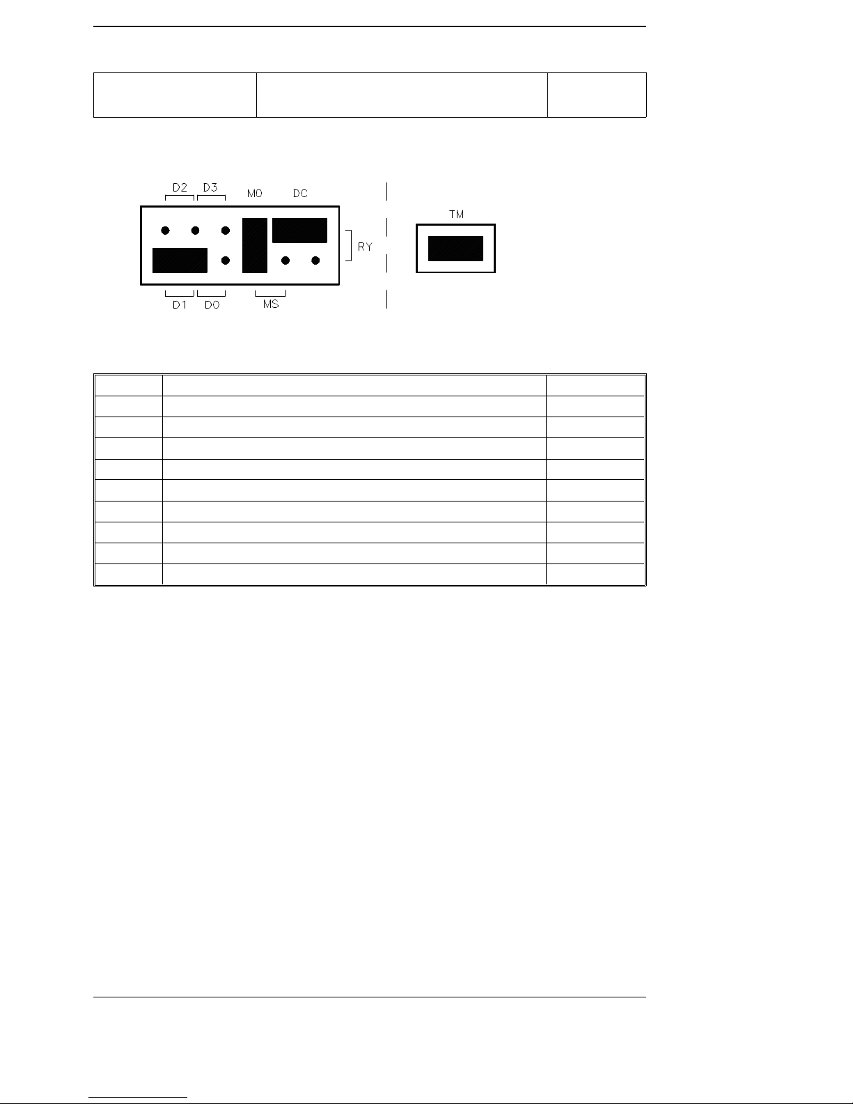
1.44 MB FDU
JUMPER DESCRIPTION SETTING
D0 Drive select ed as DRI VE 0 OFF
D1 Drive select ed as DRI VE 1 ON
D2 Drive select ed as DRI VE 2 OFF
D3 Drive select ed as DRI VE 3 OFF
MO Spindle motor control led by the Motor On signal ON
MS Spindle motor controlled by the Driv e Select signal OFF
DC Disk Change is the signal on pin 34 of the interface conn ector ON
RY Ready is the signal on pin 34 of the inter f ace connect or OFF
TM Terminator ON
PANASONIC JU-257-03T
PANASONIC JU-257-03P
SA450
4-2 3.5" MICRO FLOPPY DISK DRI V ES
Peripherals - Pocket Service Guide
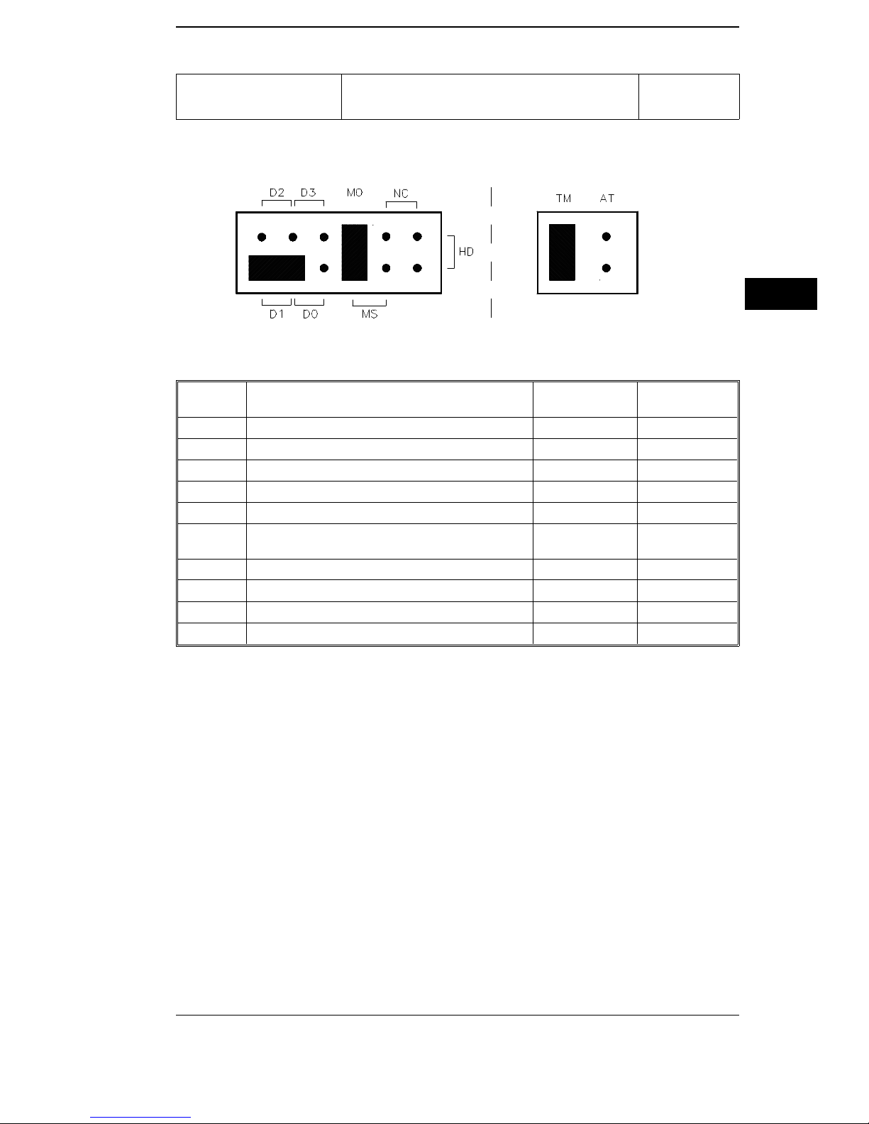
1.44 MB FDU
JUMPER DESCRIPTION
D0 Drive selected as DRIVE 0 OFF OFF
D1 Drive selected as DRIVE 1 ON ON
D2 Drive selected as DRIVE 2 OFF OFF
D3 Drive selected as DRIVE 3 OFF OFF
MO Spindle motor controlled by the Motor On signal ON ON
MS
NC Pin 2 of the interface connector is not connect ed OFF OFF
HD HD is the pin 2 output signal OFF ON
TM Terminator ON ON
AT Mode Select PS2 (OFF) or PCAT (ON) OFF OFF
Spindle motor controlled by the Drive Sele ct
signal
PANASONIC JU-257A-081P
PANASONIC JU-257A-101P
SETTING FOR
JU-257A-081P
OFF
SETTING FOR
JU-257A-101P
SA450
4
OFF
3.5" MICRO FLO PPY DISK DRIVES 4-3
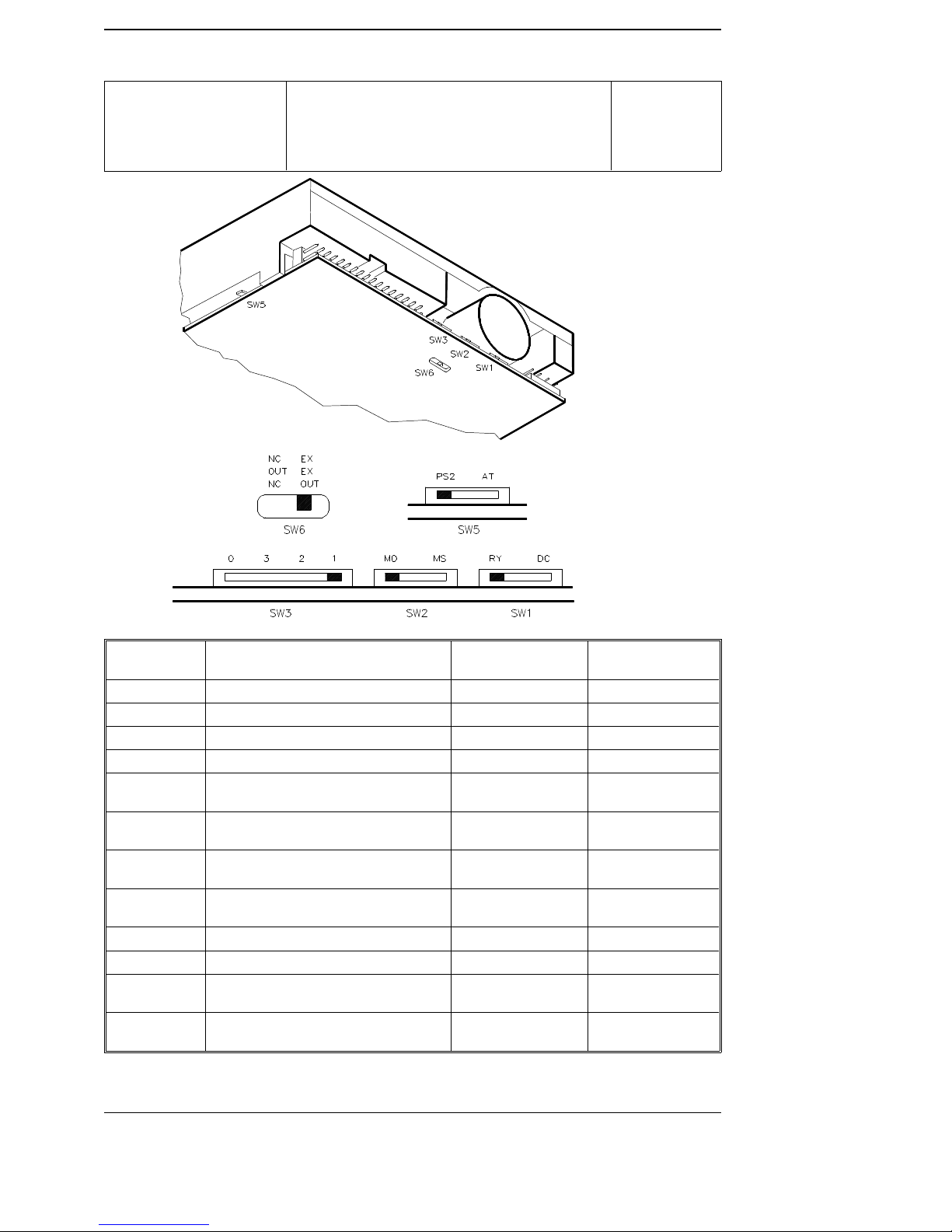
1.44 MB FDU
Peripherals - Pocket Service Guide
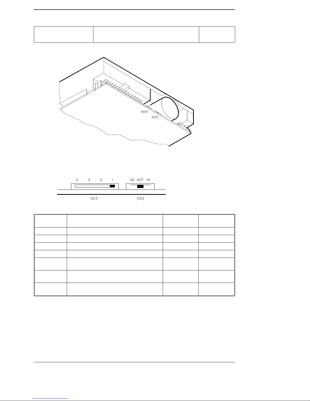
PANASONIC JU-257A-083P
PANASONIC JU-257A-083PJ
PANASONIC JU-257A-103P
PANASONIC JU-257A-103PJ
SA450
SWITCH DESCRIPTION
SW3-0 Drive selected as DRI VE 0 OFF OFF
SW3-1 Drive selected as DRI VE 1 ON ON
SW3-2 Drive selected as DRI VE 2 OFF OFF
SW3-3 Drive selected as DRI VE 3 OFF OFF
SW2-MO
SW2-MS
SW1-RY
SW1-DC
SW5-PS2 PS2 Mode Select ON ON
SW5-AT PCAT Mode Select OFF OFF
SW6
NC, OUT, NC
SW6
EX, EX, OUT
Spindle m otor cont r o lled by t he M otor
On signal
Spindle mot or cont ro l led by the Dr iv e
Select signal
Disk Change is the signal on pin 34 of
the interface connector
Ready is the signa l on pin 34 of the
interface connector
Pin 2 of the interfa ce con nect or is not
connected
HD is the output signal on pin 2 of the
interface connector
SETTING FOR
JU-257A-083P/PJ
ON ON
OFF OFF
ON ON
OFF OFF
ON OFF
OFF ON
SETTING FOR
JU-257A-103P/PJ
4-4 3.5" MICRO FLOPPY DISK DRI V ES
Peripherals - Pocket Service Guide
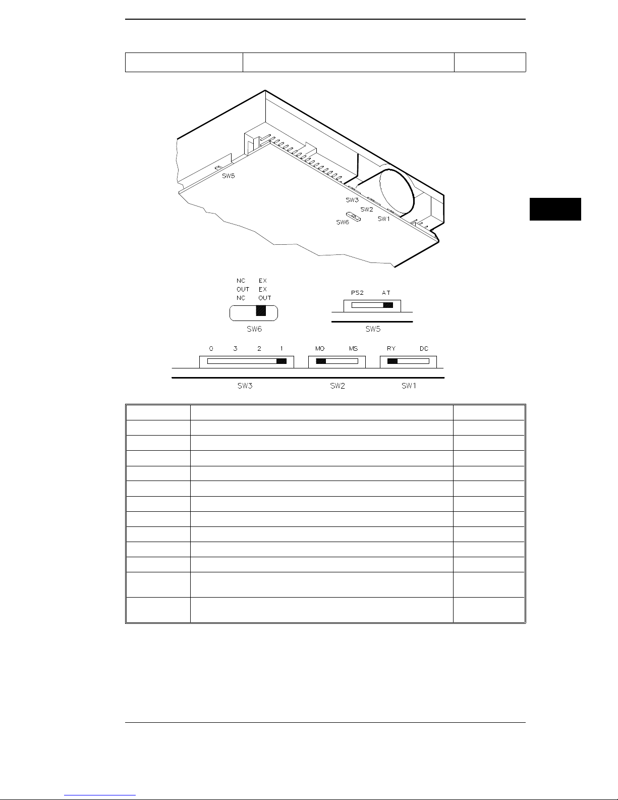
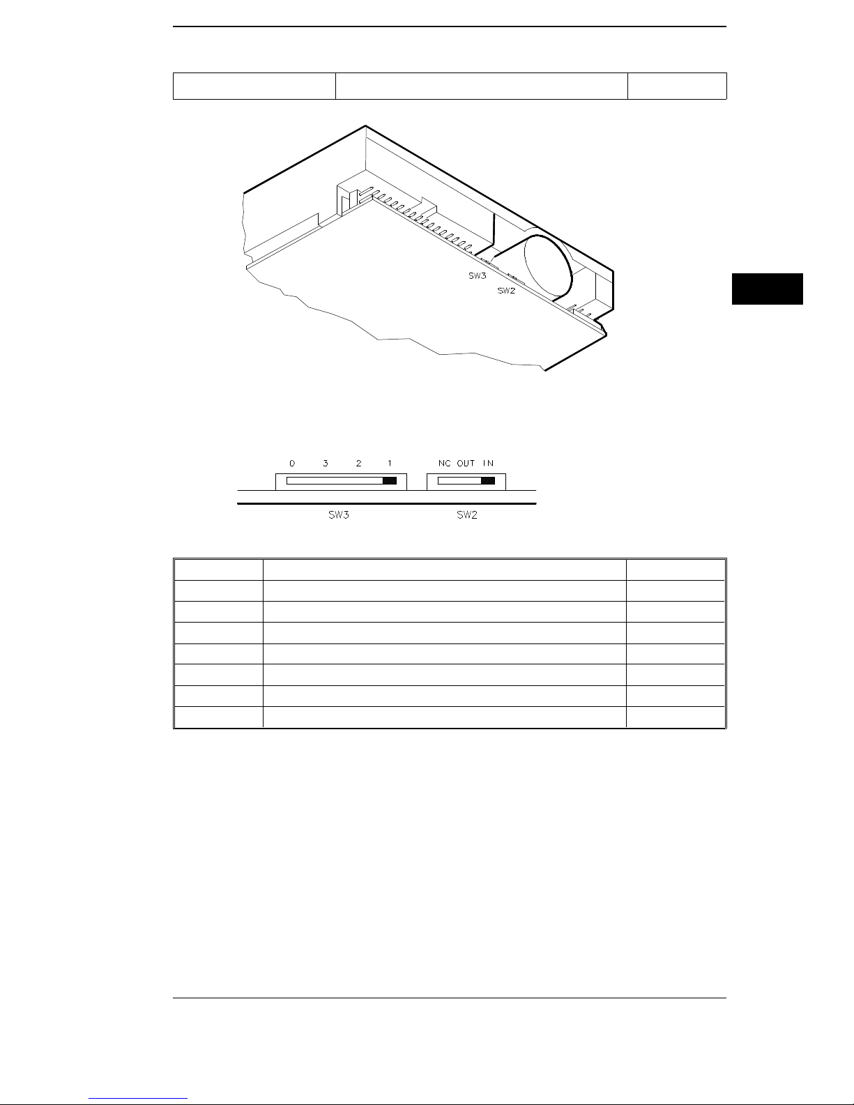
1.44 MB FDU PANASONIC JU-257A-293P SA450
4
SWITCH DESCRIPTION SETTING
SW3-0 Drive selected as DRIVE 0 OFF
SW3-1 Drive selected as DRIVE 1 ON
SW3-2 Drive selected as DRIVE 2 OFF
SW3-3 Drive selected as DRIVE 3 OFF
SW2-MO Spindle motor controlled by the Motor On signal ON
SW2-MS Spindle motor controlled by the Drive Select signal OFF
SW1-RY Disk Change is the signa l on pin 34 of the interf ace connect or ON
SW1-DC Ready is the signal on pin 34 of the interface co nnec to r OFF
SW5-PS2 PS2 Mode Select OFF
SW5-AT PCAT Mode Select ON
SW6
NC, OUT, N C
SW6
EX, EX, OUT
Pin 2 of the interface connector is not connect ed
HD is the output signa l on pin 2 of the inter face co nnec to r
OFF
ON
3.5" MICRO FLO PPY DISK DRIVES 4-5
Peripherals - Pocket Service Guide
1.44 MB FDU
PANASONIC JU-257A-84P
PANASONIC JU-257A-104P
SA450
SWITCH DESCRIPTION
SW3-0 Drive selected as DRI VE 0 OFF OFF
SW3-1 Drive selected as DRI VE 1 ON ON
SW3-2 Drive selected as DRI VE 2 OFF OFF
SW3-3 Drive selected as DRI VE 3 OFF OFF
SW2-NC
SW2-OUT
SW1-IN
Pin 2 of the interfa ce con nect or is not
connected
-HD is the output signal on pin 2 of the
interface connector
+HD is the input signal on pin 2 of the
interface connector
SETTING FOR
JU-257A-84P
ON OFF
OFF ON
OFF OFF
SETTING FOR
JU-257A-104P
4-6 3.5" MICRO FLOPPY DISK DRI V ES
Peripherals - Pocket Service Guide
1.44 MB FDU PANASONIC JU-257A-294P SA450
4
SWITCH DESCRIPTION SETTING
SW3-0 Drive selected as DRIVE 0 OFF
SW3-1 Drive selected as DRIVE 1 ON
SW3-2 Drive selected as DRIVE 2 OFF
SW3-3 Drive selected as DRIVE 3 OFF
SW2-NC Pin 2 of the interface connect or is not conne cted OFF
SW2-OU T -HD is the output signal on pin 2 of the interface con nect or OFF
SW1-IN +HD is the input signal on pin 2 of the interf ace co nnec tor ON
3.5" MICRO FLO PPY DISK DRIVES 4-7
Peripherals - Pocket Service Guide
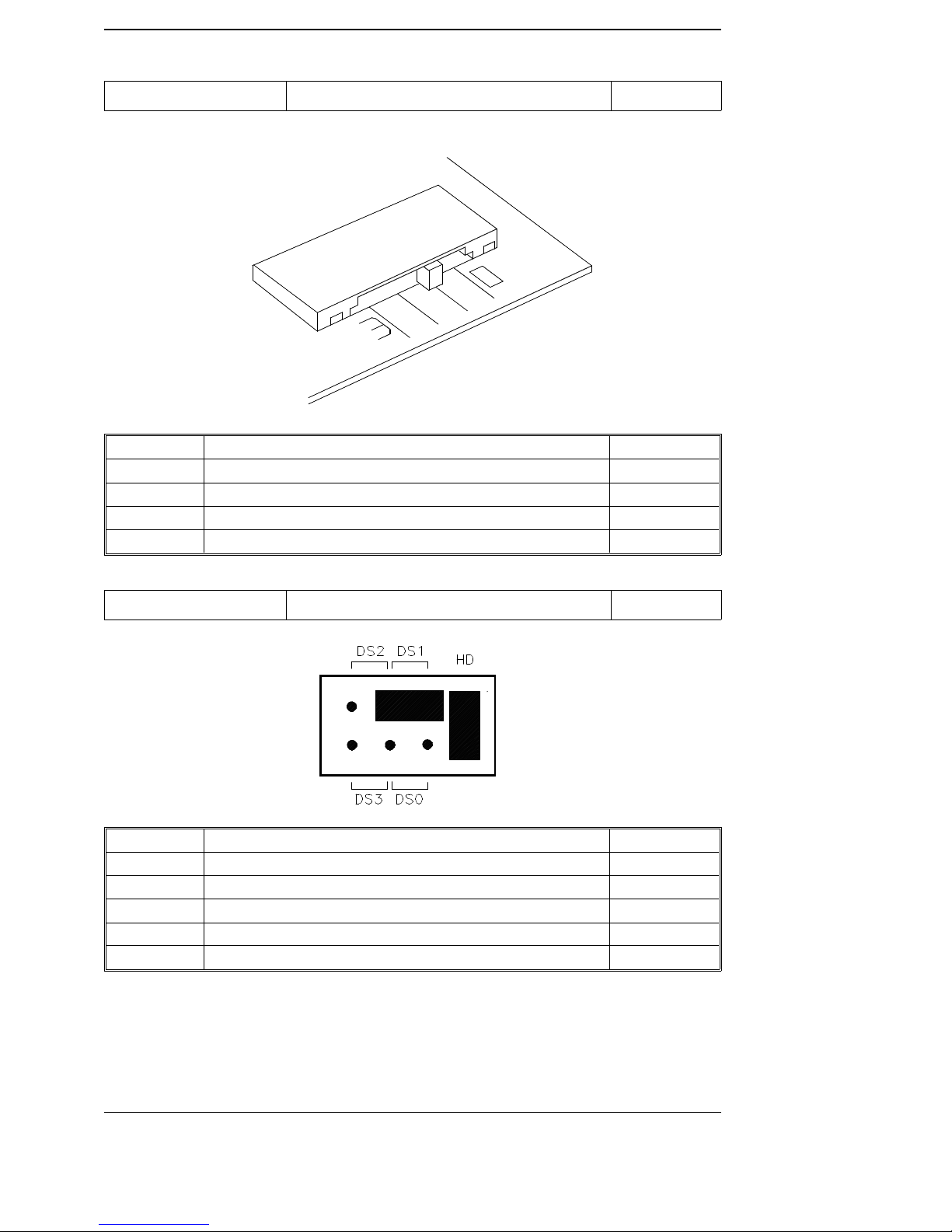
1.44 MB FDU SONY MP-F17W-80D SA450
SONY MB-F17WSONY MB-F17W
3.5’’
3.5’’
SWITCH DESCRIPTION SETTING
0 Drive select ed as DRI VE 0 OFF
1 Drive select ed as DRI VE 1 ON
2 Drive select ed as DRI VE 2 OFF
3 Drive select ed as DRI VE 3 OFF
1.44 MB FDU SONY MP-F17W-82D SA450
JUMPER DESCRIPTION SETTING
DS0 Drive select ed as DRI VE 0 OFF
DS1 Drive select ed as DRI VE 1 ON
DS2 Drive select ed as DRI VE 2 OFF
DS3 Drive select ed as DRI VE 3 OFF
HD HD sense is the signal on pin 2 of the inter f ace co nnec to r ON
4-8 3.5" MICRO FLOPPY DISK DRI V ES
Peripherals - Pocket Service Guide
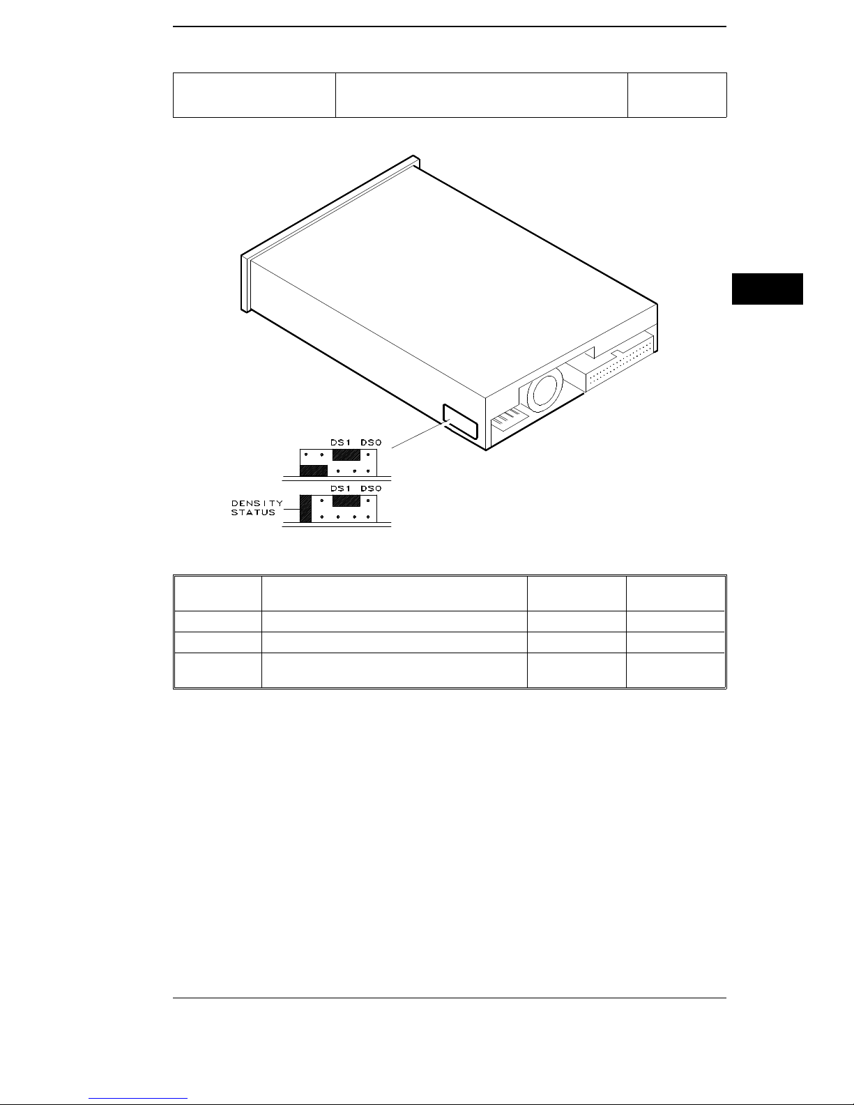
1.44 MB FDU
SONY MP-F17W- 84
SONY MP-F17W- 85
SETTING ON MODEL MP-F17-84
SA450
4
SETTING ON MODEL MP-F17-85
JUMPER DESCRIPTION
DS0 Drive selecte d as DRIVE 0 OFF OFF
DS1 Drive selecte d as DRIVE 1 ON ON
DENSITY
STATUS
Density Status is the sign al on pin 2 of the
interface co nnec to r
SETTING FOR
MP-F17-84
OFF ON
SETTING FOR
MP-F17-85
3.5" MICRO FLO PPY DISK DRIVES 4-9
 Loading...