

Panasonic JS-960WP, JS-960WP0M51, JS-960WPEM51, JS-960WP0M61, JS-960WP0R50 Operating Instructions Manual
...
Operating Instructions
POS Workstation
Model No. JS-960WP Series
English Deutsch Français Español Русский
Before operating this product, please read the instructions carefully and save this
manual for future use.
JS-960WP0R50

For USA
For USA
Federal Communications Commission Radio Frequency Interference Statement
This equipment has been tested and found to comply with the limits for a Class A digital
device, pursuant to Part 15 of the FCC Rules. These limits are designed to provide
reasonable protection against harmful interference when the equipment is operated in a
commercial environment.
This equipment generates, uses and can radiate radio frequency energy and, if not
installed and used in accordance with the instructions, may cause harmful interference to
radio communications. Operation of this equipment in a residential area is likely to cause
harmful interference in which case the user will be required to correct the interference at
his own expense.
This device complies with Part 15 of the FCC Rules. Operation is subject to the following
two conditions: (1) This device may not cause harmful interference, and (2) this device
must accept any interference received, including interference that may cause undesired
operation.
This unit must be connected to a grounded power outlet.
Battery
This product contains a CR Coin Cell Lithium Battery which contains Perchlorate
Material-special handling may apply.
See www.dtsc.ca.gov/hazardouswaste/Perchlorate.
For CANADA
For CANADA
This Class A digital apparatus complies with Canadian ICES-003.
Cet appareil numérique de la classe A est conforme à la norme NMB-003 du Canada.
This unit must be connected to a grounded power outlet.
Cette unité doit être branchée sur une prise de courant mise à la terre.
2
For EU
English
Warning :
This is a class A product. In a domestic environment, this product may cause radio interference in
which case the user may be required to take adequate measures.
This unit must be connected to a grounded power outlet.
Deutsch [German]
Warnung :
Dies ist ein Produkt der Klasse A. Wenn im Heim betrieben, kann das Produkt
Hochfrequenzstörungen verursachen, gegen die der Benutzer u.U. geeignete Maßnahmen treffen muss.
Dieses Gerät muss an eine vorschriftsmäßig geerdete Netzsteckdose angeschlossen werden.
Français [French]
Avertissement :
Il s'agit d'un produit de classe A. Dans un environnement privé, ce produit risque de créer des
interférences radio auquel cas des mesures correctives adéquates peuvent être exigées de la part
de l'utilisateur.
Cette unité doit être branchée sur une prise de courant mise à la terre.
Česky [Czech]
Upozornění :
Toto je výrobek třídy A. Ve vnitřním prostředí může tento výrobek způsobovat rádiové rušení. V
takovém případě může být požadováno, aby uživatel přijal příslušná opatření.
Dansk [Danish]
Advarsel :
Dette er et klasse-A produkt. I hjemmeomgivelser kan dette produkt forårsage radiostøj, i hvilket
tilfælde brugeren kan være nødsaget til at træffe fyldestgørende forholdsregler.
Suomi [Finnish]
Varoitus :
Tämä on luokan A tuote. Kotiympäristössä tämä tuote saattaa aiheuttaa häiriöitä radiolähetyksiin,
jolloin käyttäjän tulee kenties suorittaa asianmukaiset toimenpiteet.
Laite on liitettava suojamaadoituskoskettimilla varustettuun pistorasiaan.
3
For EU
Norsk [Norwegian]
Advarsel :
Dette er et klasse A produkt. Ved innendørs bruk kan dette produktet forårsake radiointerferens. I
slike tilfeller kan det være nødvendig for brukeren å treffe nødvendige tiltak.
Apparatet ma tilkoples jordet stikkontakt.
Svenska [Swedish]
Varning :
Detta är en klass A produkt. I inomhusmiljö kan denna produkt orsaka radiostörningar. I sådant fall
åligger det användaren att vidta lämpliga åtgärder.
Apparaten skall anslutas till jordat uttag.
Slovenčina [Slovak]
Upozornenie :
Toto je výrobok triedy A. Vo vnútornom prostredí môže tento výrobok spôsobovať rádiové rušenie. V
takom prípade môže byť požadované, aby používateľ prijal príslušné opatrenia.
Italiano [Italian]
Attenzione :
Questo è un prodotto di classe A. In ambiente domestico, questo prodotto può causare interferenze
radio, nel qual caso può essere necessario che l'utente adotti misure adeguate.
Español [Spanish]
Aviso :
Éste es un producto de clase A. En la instalación en una vivienda, este producto puede causar
interferencias de radio, en cuyo caso puede resultar necesario que el usuario tome medidas
pertinentes.
Esta unidad deberá conectarse a una toma de corriente conectada a tierra.
Nederlands [Dutch]
Waarschuwing :
Dit is een Klasse A product. In een huiselijke omgeving kan dit product radiostoring veroorzaken, in
welk geval de gebruiker verplicht kan zijn afdoende tegenmaatregelen te nemen.
Português [Portuguese]
Advertência :
Este é um produto da classe A. Quando este produto for utilizado num ambiente doméstico, poderá
provocar interferências radiofónicas e, neste caso, pode ser necessário que o utilizador tome as
providências adequadas.
4

Importer’s name and address to follow EU rules:
Panasonic Testing Centre
Panasonic Marketing Europe GmbH
Winsbergring 15, 22525 Hamburg, F. R. Germany
5
For Arabic Countries
[Arabic]
For Russia
Русский [Russian]
Предупреждение :
Это изделие класса А. В домашних условиях данное изделие может вызвать радиопомехи, что
может требовать от пользователя принятия соответствующих мер.
Это устройство необходимо подсоединять к заземленной сетевой розетке.
For Korea
상호 또는 성명 : Panasonic Korea Ltd.(PKL)
기기의 명칭 : POS Workstation
기본모델명 : JS-960WS0M51/ JS-960WS0M53/ JS-960WP0M51
인증 번호 : KCC-REI-PKL-JS960
제조자 / 제조국가 : USI Electronics (Shenzhen) Co., Ltd./ China
제조날짜 : 본체 밑면의 시리얼 번호를 참조하시기 바랍니다 .
yymXXXXXX
yy: 년도 표시 (yy means year) (2011 = 11, 2012 = 12,.....)
m: 월 표시 (m means month)
A: 1월 B: 2 월 C: 3 월 D: 4 월 E: 5 월 F: 6 월
H: 7 월 J: 8 월 K: 9 월 L: 10 월 M: 11 월 N: 12 월
주의사항
이 기기는 업무용으로 전자파적합등록을 한 기기이오니 판매자 또는 사용자는 이 점을
주의하시기 바라며 만약 잘못 판매 또는 구입하였을 때에는 가정용으로 교환하시기
바랍니다 .
본 장치는 접지된 전원 콘센트에 연결해야 합니다 .
6
For Taiwan
甲類
此設備經測試證明符號BSMI(經濟部標準檢驗局)之甲類數位裝置的限制規定。這些限制的
目的是為了在商業環境中使用此設備時,能提供合理的保護以防止有害的干擾。此設備會產
生、使用並散發射頻能量:如果未導照製造廠商的指導手冊來安裝和使用,可能會干擾無線
電通訊。請勿在住宅區使用此設備。
警告使用者:
這是甲類的資訊產品,在居住的環境中使用時,可能會造成射頻干擾,在這種情況下,使
用者會被要求采取某些適當的對策。
本機必須連接至接地的電源插座。
安全:電池處理
警告:新電池安裝不正解會有爆炸的危險。更換電池時,請僅使用相同或製造商建議
的同等類型電池。請勿將廢棄電池丟棄於一般垃圾中。請聯絡當地廢棄物處理機構以
獲取有關最近的廢棄電池存放站的地址。
您的電腦使用鋰幣電池。鋰幣電池為長效用電池,很有可能您永遠都不需要更換
它。然而,如果確實需要更換,請參閱您的電腦說明文件。
請勿將廢棄電池丟棄於一般垃圾中。請聯絡當地廢棄物處理機構以獲取有關最近
的廢棄電池存放站的地址。
安全:電池聲明(台灣)
廢電池請回收
7

For Taiwan
商 品 名 稱 :收銀機
型 號 : JS-960WP, JS-960WP0M51, JS-960WPEM51,
JS-960WP0M61, JS-960WP0R50, JS-960WP0R51
額 定 電 源 :24 V
進 口 商 :台松電器販賣股份有限公司
聯 絡 地 址 :新北市中和區員山路579 號
電 話 :(02)2227-6100
製造或委製廠商 :松下系統網絡科技株式會社 日本 福岡
生 產 地 :中國大陸
製 造 年 份 及
製 造 號 碼 :请参照实体底面的串行号码
:yymXXXXXX
:yy: 年度表示 (yy means year) (2011=11, 2012 =12,.....)
:m: 月表示 (m means month)
:A: 1 月 B: 2 月 C: 3 月 D: 4 月 E: 5 月 F: 6 月
:H: 7 月 J: 8 月 K: 9 月 L: 10 月 M: 11月 N: 12月
/ 6.67 A
D31221
8

Contents
Read Me First .......................................................................................... 10
Introduction ....................................................................................................... 10
Disclaimer of Warranty .......................................................................... 12
Safety Precautions ................................................................................. 13
Precautions for Use................................................................................ 15
Confirmation of Accessories ................................................................. 16
Names of Parts and Their Functions .................................................... 17
AC Adapter Installation .......................................................................... 20
Turning the Power On and Off ............................................................... 21
How to turn the power on ................................................................................. 21
How to turn the power off ................................................................................. 21
English
Display Unit Replacement ..................................................................... 22
When fixing parts that use VESA mounts are not installed .............................. 22
When fixing parts that use VESA mounts are installed .................................... 24
Storage Unit Replacement ..................................................................... 26
Rear Display Unit Installation ................................................................ 28
MSR Unit (Short Type) Installation ........................................................ 30
MSR Unit (Long Type) Installation ........................................................ 32
Fingerprint Sensor Kit Installation ........................................................ 34
Specifications ......................................................................................... 38
Cleaning .................................................................................................. 40
Maintenance ............................................................................................ 40
Troubleshooting ..................................................................................... 40
9

Read Me First
■Introduction
Thank you for purchasing the JS-960WP series Panasonic POS Workstation.
This manual describes the instructions for the POS Workstation.
Please read this manual carefully before using this product.
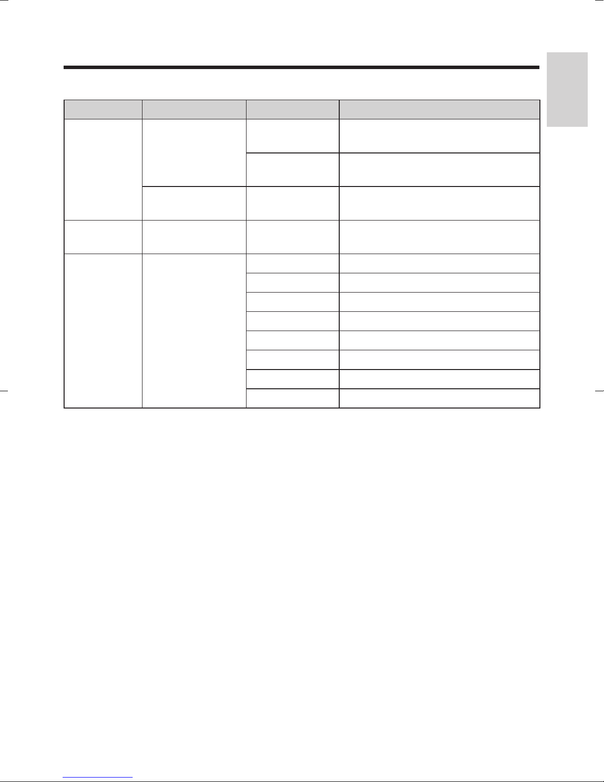
List of models
Model No. Display Style
JS-960WPUR50
JS-960WPUC51
JS-960WPEM51
JS-960WP0M51
JS-960WP0M61
JS-960WP0R50
JS-960WP0R51
15 inch
LCD
15 inch
LCD
15 inch
LCD
15 inch
LCD
15 inch
LCD
15 inch
LCD
15 inch
LCD
VESA
Panel
VESA
Panel
VESA
Panel
VESA
Panel
VESA
Panel
VESA
Panel
VESA
Panel
Touch
Panel
Resistive
Capacitive
Capacitive
Capacitive
Capacitive
Resistive
Resistive
CPU
®
Intel
Celeron
®
P4500
1.86 GHz
®
Intel
Celeron
®
P4500
1.86 GHz
®
Intel
Celeron
®
P4500
1.86 GHz
®
Intel
Celeron
®
P4500
1.86 GHz
®
Intel
Core™ i5
520 M
2.4 GHz
®
Intel
Celeron
®
P4500
1.86 GHz
®
Intel
Celeron
®
P4500
1.86 GHz
Magnetic
Stripe
Reader
— —
12.1 inch
(Short Type)
(ISO, Dark)
15 inch
(Long Type)
(ISO, White)
15 inch
(Long Type)
(ISO, Dark)
15 inch
(Long Type)
(ISO, Dark)
— —
12.1 inch
(Short Type)
(ISO, Dark)
Rear
Display
—
—
—
—
—
Celeron and Intel Core are trademarks of Intel Corporation in the U.S. and/or other
countries.
10
List of optional accessories
Unit Name Model No. Remarks
English
ID Module
MSR Unit
Unit
Fingerprint
Sensor Kit
Rear Display
Unit
Rear Display Unit JS-960RD-020
AC Cord Kit AC Cord Kit
JS-960MG-010
JS-960MG-020
Magnetic Stripe Reader Module
(Short Type)
Magnetic Stripe Reader Module
(Long Type)
JS-960FPK010 Fingerprint Sensor Kit
Rear Display Module 2 Line
(VESA Type)
JS-950KT-UH0 AC Cord Kit UH
JS-950KT-UM0 AC Cord Kit UM
JS-950KT-F10 AC Cord Kit F
JS-950KT-K10 AC Cord Kit K
JS-950KT-W10 AC Cord Kit W
JS-950KT-Z10 AC Cord Kit Z
JS-950KT-A25 AC Cord Kit A
JS-950KT-E25 AC Cord Kit E
11

Disclaimer of Warranty
IN NO EVENT SHALL Panasonic System Networks Co., Ltd. BE LIABLE TO ANY PARTY
OR ANY PERSON, EXCEPT FOR REPLACEMENT OR REASONABLE MAINTENANCE
OF THE PRODUCT, FOR THE CASES, INCLUDING BUT NOT LIMITED TO BELOW:
ANY DAMAGE AND LOSS, INCLUDING WITHOUT LIMITATION, DIRECT OR
INDIRECT, SPECIAL, CONSEQUENTIAL OR EXEMPLARY, ARISING OUT OF
RELATING TO THE PRODUCT;
PERSONAL INJURY OR ANY DAMAGE CAUSED BY INAPPROPRIATE USE OR
NEGLIGENT OPERATION OF THE USER;
UNAUTHORIZED DISASSEMBLE, REPAIR OR MODIFICATION OF THE PRODUCT
BY THE USER;
LOSS OF REGISTERED DATA BY ANY FAILURE.
12

Safety Precautions
■POS Workstation: JS-960WP series
IMPORTANT
Install a socket outlet adjacent to the equipment so that it will be easily accessible.
CAUTION
RISK OF EXPLOSION IF BATTERY IS REPLACED BY AN INCORRECT TYPE.
DISPOSE OF USED BATTERIES ACCORDING TO THE INSTRUCTIONS.
Avoid radio frequency interference
Do not place the POS Workstation near a television or radio receiver.
Avoid stacking
Do not place heavy objects on the POS Workstation.
Keep small objects away
Do not insert paper clips or other small objects into POS Workstation.
There is the risk of heat, fire or explosion.
Keep dry
There is the risk of heat, fire or explosion.
English
Do not disassemble the POS Workstation
Do not attempt to disassemble the POS Workstation. There is the risk of heat, fire or
explosion.
Do not touch the plug with wet hands
There is the risk of electric shock.
Be certain to plug fully into the outlet
There is the risk of electric shock or fire.
Unplug this unit from power outlets if it emits smoke, an abnormal smell or makes
unusual noise.
These conditions can cause fire or electric shock. Confirm that smoke has stopped and
contact an authorized service center.
When unplugging, make sure to hold the body of the plug
If the power cord or outlet is damaged, there is a risk of electric shock, short circuit or fire.
Do not use a damaged power cord or plug
There is the risk of electric shock or fire.
Do not use the provided power cord and the AC adapter for anything other than the
POS Workstation.
There is the risk of electric shock or fire.
13

Safety Precautions
Clean the dust off the plug, periodically
There is the risk of heat or fire.
Do not use with any other battery
Please use the specified battery.
CAUTION: Risk of explosion if battery is replaced by an incorrect type. Dispose of used
batteries according to the instructions and local requirements.
Do not touch the power-cord or plug during a storm
There is the risk of electric shock or fire.
Do not use the POS Workstation outdoors
This product assumes the indoor use. There is the risk of breakdown.
Do not put the POS Workstation on a slope or an unstable place
This can cause damage to the unit or injury by falling.
Select an installation area that can support the total weight
Selecting an inappropriate installation surface may cause the product to fall down or topple
over, resulting in injury. Installation work shall be started after sufficient reinforcement.
Periodic inspections shall be conducted
Rust on the metal parts or screws may cause a fall of the product resulting in injury or
accidents.
Consult the dealer for the inspections.
The measures of protection against a fall of this product shall be taken
Failure to observe this may cause a drop resulting in injury.
Be sure to install the safety wire.
The screws and bolts must be tightened to the specified torque
Failure to observe this may cause a drop resulting in injury or accidents.
Note:
Do not open the rear cover and the filter cover while the POS Workstation is operating.
14

Precautions for Use
Attention for capacitive touch screen
Do not touch it by finger nail, because capacitive touch screen can not recognize it.
Touch it by finger tip.
Do not touch it during startup. It initializes touch screen during startup. If it is touched
during startup, touch screen is not initialized correctly.
Be careful to not accidentally touch around display edges or press on display bezel as it
can negatively affect display touch sensor accuracy.
Touch screen calibration can be affected by atmospheric change. In case of calibration
shifted, perform a calibration adjustment.
Adequacy of touch screen reaction-time or sensitivity may vary by operator. Display
sensitivity can be adjusted by executing a display sensitivity adjustment program.*
Capacitive touch-screen panel uses radio frequency to detect finger tip touch. Terminals
are configured to use different frequencies to avoid conflict in the event of two or more
terminals operating within 1.5 m (approx. 5 inches) of each other. In the event of conflict
('ghost' or inexplicable touch-screen reaction(s)), shutdown and reboot the terminal to
reselect touch screen frequency.
English
* Inquire to the supplier about the display sensitivity adjustment program.
Carrying/moving terminals
Do not lift or carry the terminal by holding the cable cover. Lift and carry the terminal by
securely holding the main unit from the bottom, with two hands.
Procure fixing screws separately.
The screws that secure this product are not supplied. Prepare them according to the
material and strength of the area where the product is to be installed.
Screw tightening
The screws and bolts must be tightened with an appropriate tightening torque according
to the material and strength of the installation area.
Do not use an impact driver. Use of an impact driver may damage the screws or cause
tightening excessively.
When a screw is tightened, make the screw at a right angle to the surface. After
tightening the screws or bolts, perform visual check to ensure tightening is enough and
there is no backlash.
Be sure to remove this product if it is not in use.
15
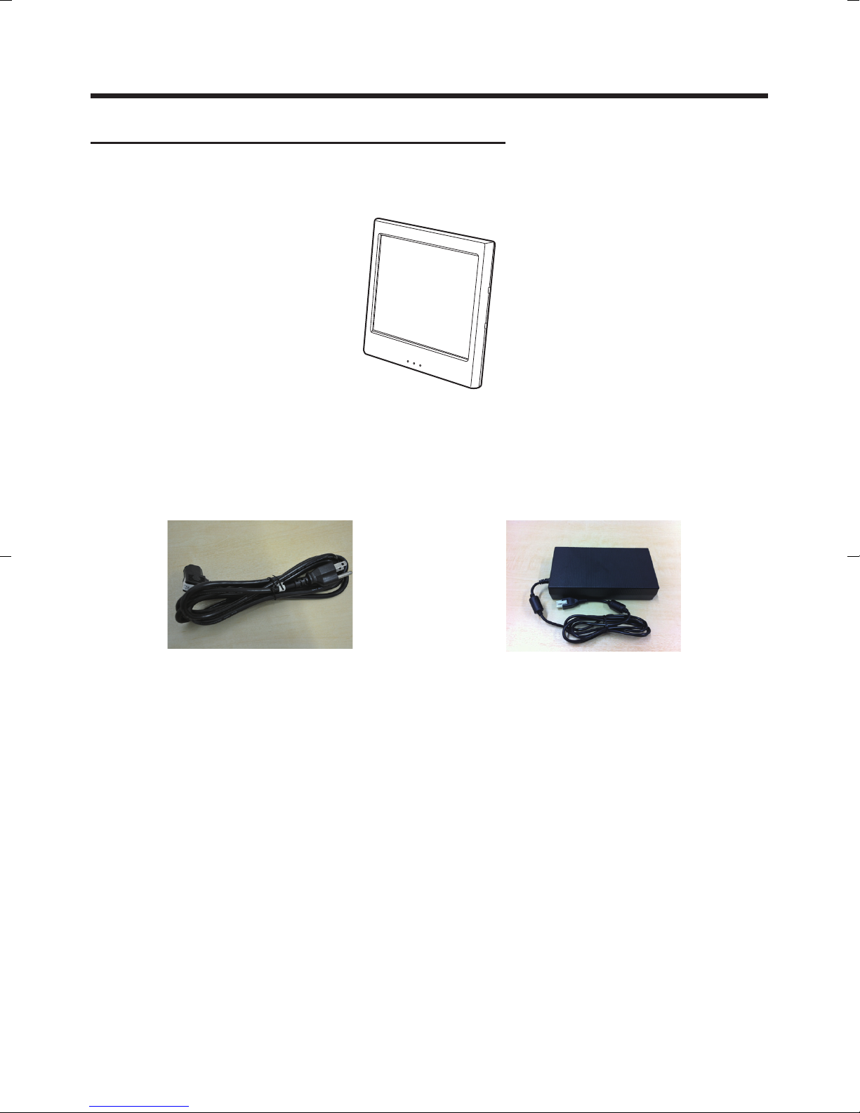
Confirmation of Accessories
Before using, check the following accessories.
In case some items are missing, contact your dealer.
■Main Body
■AC Cord (JS-950KT-UH0)
This is supplied together with the models
which have the following model numbers:
JS-960WPUR50, JS-960WPUC51.
An AC cord is not supplied together with the models which have the following model
numbers:
JS-960WPEM51, JS-960WP0M51, JS-960WP0M61, JS-960WP0R50, JS-960WP0R51.
■AC Adapter
16
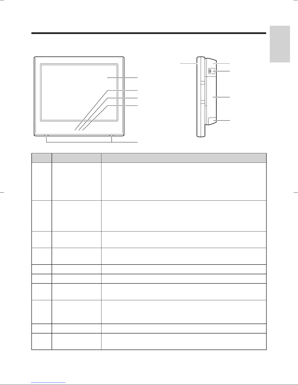
Names of Parts and Their Functions
■Front ■Right side
No. Name Functions
Used for displaying information such as operation methods.
The information to be displayed can be set using
application software.
This display can be used also as a touch panel for input
operation.
1
Operator’s
Display
English
2
3
4
5
6
7
8
9
:
Lights yellow or green: Operating
Power Status
LED
LAN Status
LED
HDD Status
LED
Speaker Used for playing sound.
Display Unit The unit which includes the operator’s display.
Cable Cover
Cable Cover
Release
Button
Main Unit This unit contains the I/O port and the storage unit.
Thumbscrew
Cover
Lights red: Power off
Flashes yellow or green: Standby
Flashes red: Suspended
Flashes yellow or green: Communicating
Flashes yellow or green: Accessing HDD
Cover of the cables for connecting the main unit and the
display unit.
Push when remove the cable cover.
Cover of the thumbscrews which fix the display unit.
17
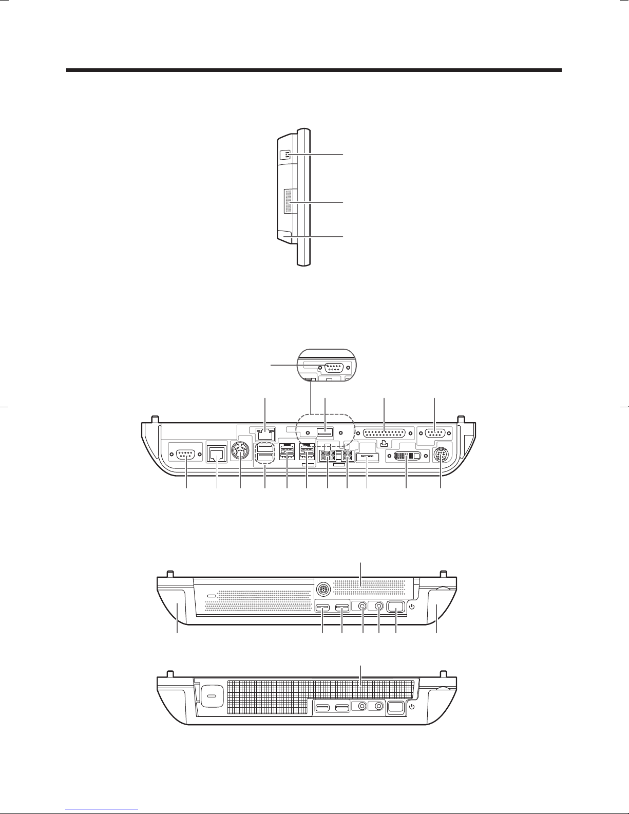
Names of Parts and Their Functions
■Left side
■Top (without the cable cover)
RS232C type
■Bottom
Without filter
With filter
USB type
18
No. Name Functions
English
;
<
=
>
?
@
A
B
C
D
E
F
G
H
Vent Used for outtaking the cooling air.
Serial Port 1
Serial Port 2
Used for connecting a serial device.
Serial Port 3
LAN Port Used for connecting a LAN cable.
Parallel Port Used for connecting a parallel device.
Cash Drawer
Port 1
Used for connecting a cash drawer.
Cash Drawer
Port 3
USB Port
USB Port (12V)
Used for connecting a USB device.
USB Port (24V)
DC Input Used for DC input.
HDD Power Used for connecting HDD power cable.
eSATA Port Used for connecting HDD (eSATA).
I
J
K
L
M
N
O
DVI-I Port Used for connecting DVI-I device.
Rear Display
Port
Used for connecting the rear display.
HDD Cover Open when installing the storage unit in the display unit.
Audio OUT Used for connecting an audio device.
MIC IN Used for connecting a microphone.
Power Switch Turns on/off the power.
Filter Used for filtering air.
19
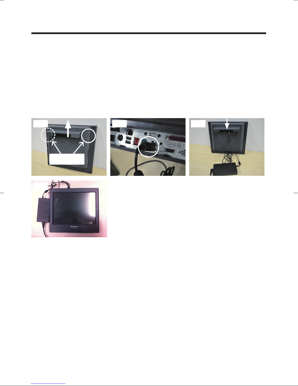
AC Adapter Installation
(1) While pushing in the cable cover release button, slide the cable cover with both hands
to remove it.
(2) Connect the DC output connector of the AC adapter to the DC input connector.
Push the AC cord connector all the way into the AC IN side of the AC adapter to
connect it.
Pull gently on the connector to make sure that the connector is locked in place. After
pulling on the connector, push it in again.
(3) Push firmly on the cable cover with both hands until it clicks to lock it into place.
(4) Carefully replace the main unit on a clear, flat surface.
(2) (3)(1)
Cable cover
release button
(4)
20
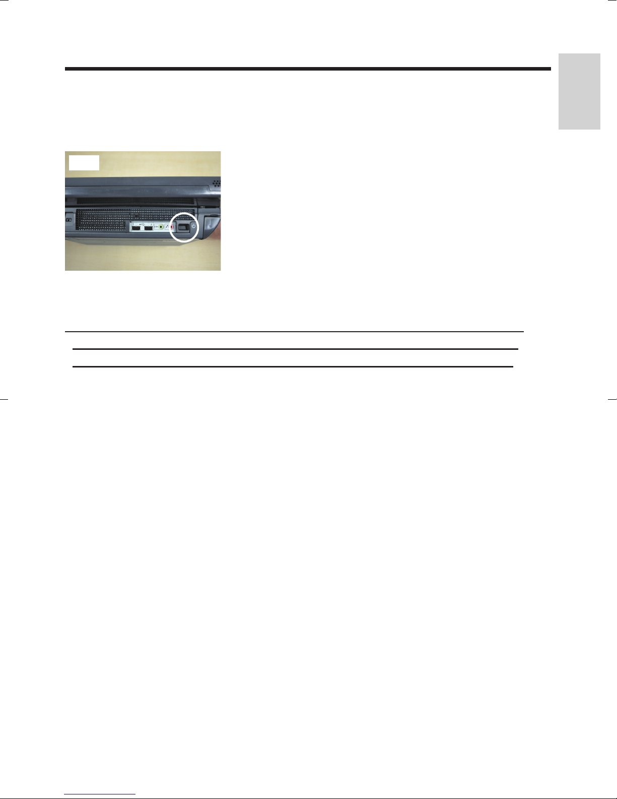
Turning the Power On and Off
■ How to turn the power on
(1) Press the power switch.
The power status LED will light up in green.
(1)
■ How to turn the power off
*Be sure to save required data and close all application software before
turning off the power. To protect data in case of a power failure, use a
English
power backup device such as an uninterruptible power supply (UPS).
(1) Press the power switch.
The power status LED will light up in red.
21
Display Unit Replacement
Be sure to disconnect the power cable of the main block (POS Workstation) and
confirm the power is “OFF” before the operation below.
■When fixing parts that use VESA mounts are not installed
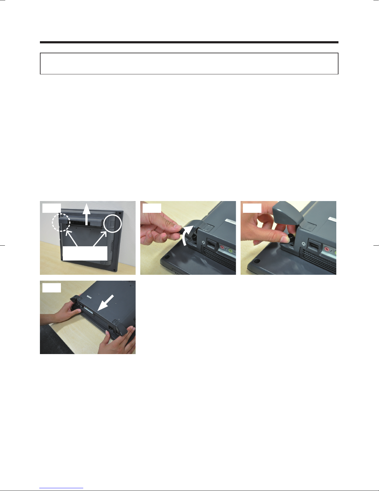
(1) While pushing in the cable cover release button, slide the cable cover with both hands
to remove it.
Perform the work on a flat surface.
Place a non-slip mat on the surface to make the work easier.
(2) Open the screw covers (2 locations) of the main unit.
(3) Loosen the 2 thumbscrews securing the display unit.
Loosen the thumbscrews until they are extended by their springs.
If you continue to loosen the thumbscrews further after they are extended, they
could become detached. Make sure not to detach them.
(4) Hold the both sides of the display unit and pull out the unit slowly.
(1)-1 (3)
Cable cover
release button
(4)
(2)(1)
22
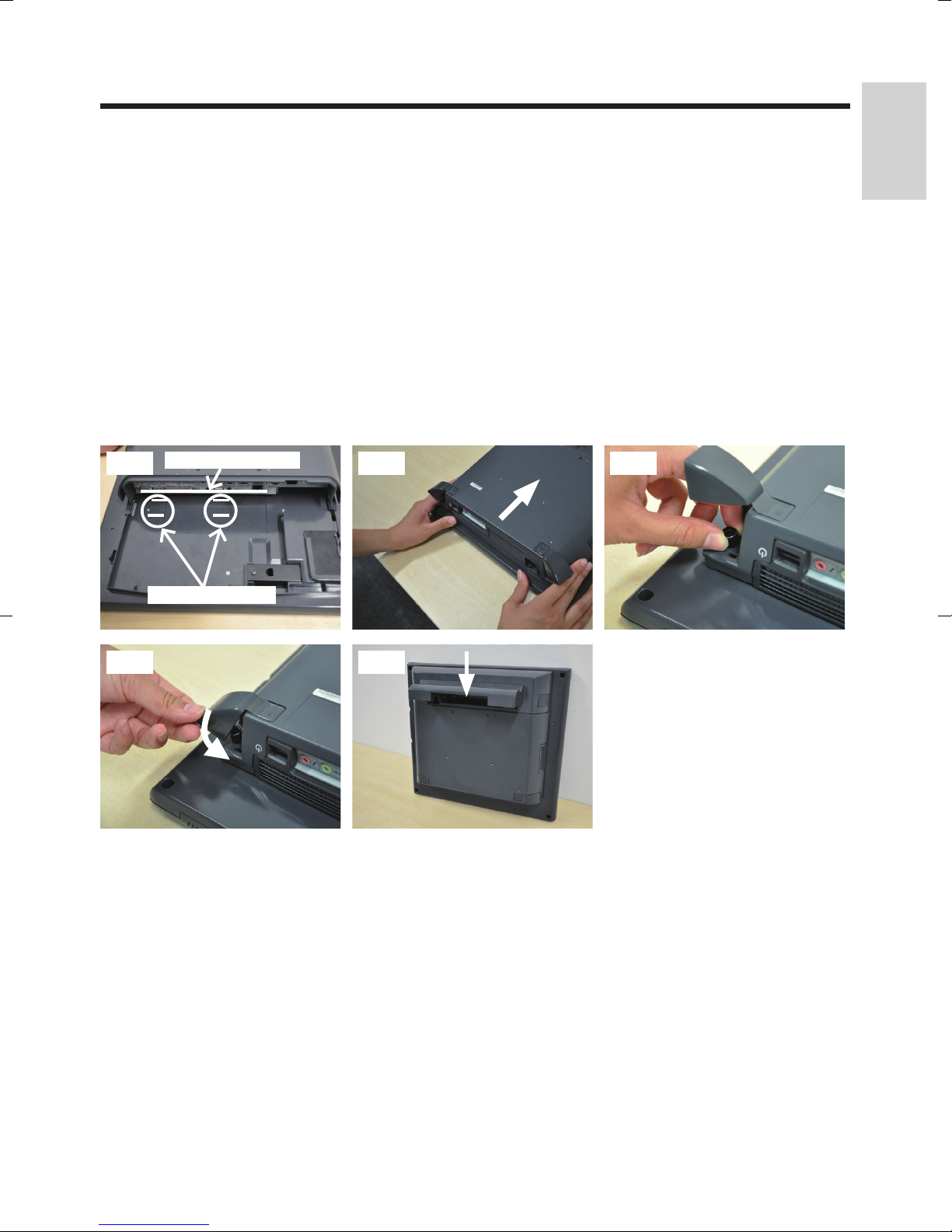
(5) Place the new display unit on a flat surface, hold the main unit with both hands, and
place the main unit so that the edges of the main unit IO panel are aligned within the
two positioning lines on the display unit. Then, slide the main unit slowly towards the
top side of the display unit to connect the connector of the main unit and the connector
of the display unit.
Do not press the rear surface of the display unit. (Doing so may damage the
functionality of the LCD or touch panel.)
(6) Tighten the two thumbscrews of the main unit by hand to secure the display unit, and
close the thumbscrew covers of the main unit.
Be sure to use hand when tightening the thumbscrews.
Make sure that no looseness is detected when trying to move the display unit.
(7) Return the cable cover to its original position, and close the cable cover.
English
(5)-1 (6)-1
(6)-2
Edge of IO panel
Positioning lines
(5)-2
(7)
23

Display Unit Replacement
Be sure to disconnect the power cable of the main block (POS Workstation) and
confirm the power is “OFF” before the operation below.
■When fixing parts that use VESA mounts are installed
(1) While pushing in the cable cover release button, slide the cable cover with both hands
to remove it.
(2) Open the screw covers (2 locations) of the main unit.
(3) Loosen the 2 thumbscrews securing the display unit.
pThe thumbscrews shall be loosened until the screws rotate without resistance.
(4) Hold both sides of the display unit and slide it out slowly to remove it.
(1)-1
Cable
cover
release
button
(3)
(1)-2
(4)
(2)
24

(5) Hold the new display unit with both hands and insert the connector section of the
display unit into the connector inlet guide of the main unit slowly to connect the
connector.
When the connector section is connected, do not press the LCD surface of the
display unit.
(Failure to observe this may result in damage to functions of the LCD or touch
panel.)
(6) Tighten the 2 thumbscrews of the main unit by hand to secure the display unit.
Be sure to use hand when tightening the thumbscrews.
Make sure that no looseness is detected when trying to move the display unit.
(7) Close the thumbscrew covers of the main unit, and close the cable cover.
English
(5)
(6)
(7)
25
Storage Unit Replacement
Be sure to disconnect the power cable of the main block (POS Workstation) and
confirm the power is “OFF” before the operation below.
*Make sure to ground the unit before starting this work.
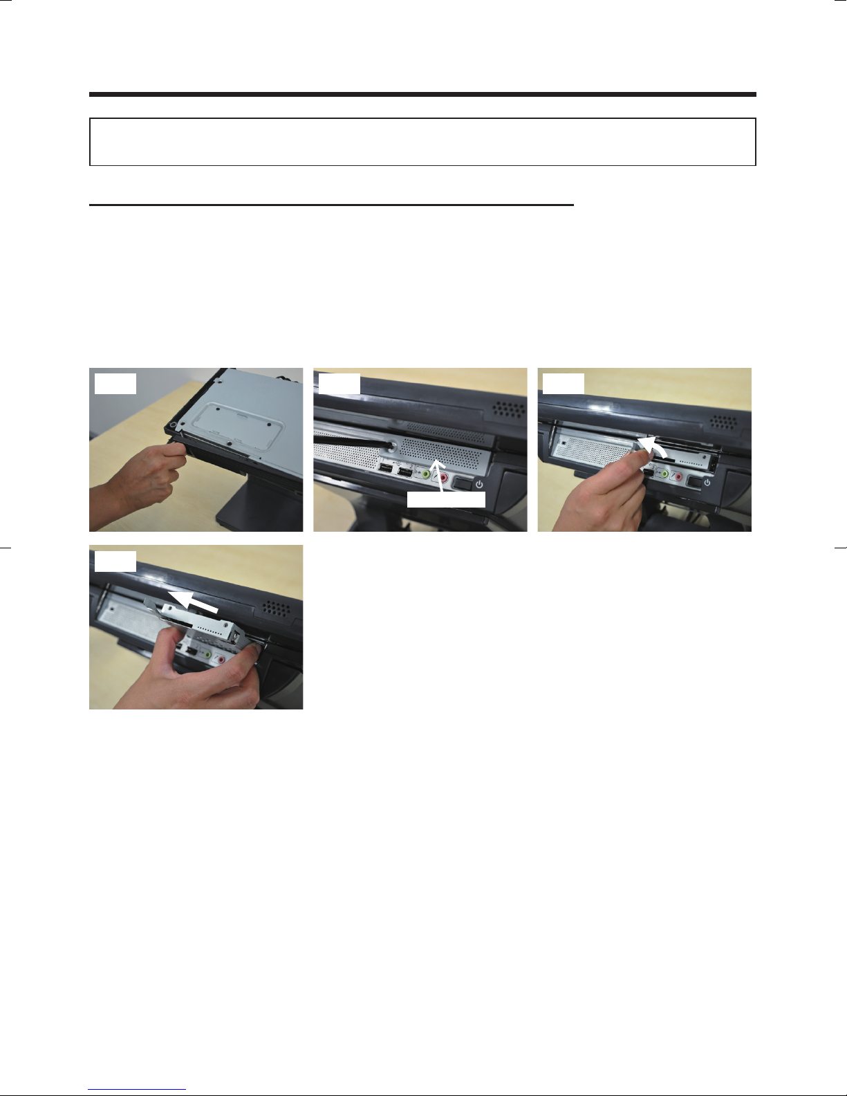
(1) Grasp the tab on the left side of the filter and pull it towards you to remove the filter.
Do not use excessive force to open the filter.
There is also a hook in the center, so pull the filter gently towards you.
(2) Remove the screw (1 piece) that secures the HDD cover, and then remove the HDD
cover.
(3) Pull the eject lever of the storage unit and remove the storage unit slowly.
(1)
(3)-2
(3)-1(2)
HDD cover
26
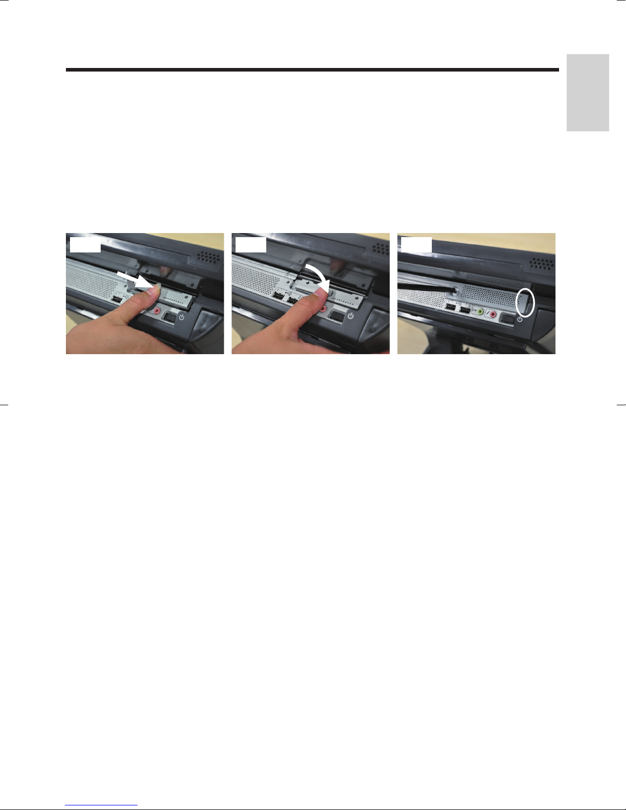
(4) Slowly insert a new storage unit into the main unit and connect the connector of the
main unit with the connector of the storage unit.
Make sure that the eject lever of the storage unit is in the open position before
inserting the new storage unit.
Push the center of the storage unit all the way in, and return the eject lever to its
original position to secure the storage unit.
(5) Insert the right side tab of the HDD cover, and secure it with the screw.
(6) Follow steps (5) to (7) in “Display Unit Replacement” to reattach the display unit.
(4)-1 (4)-2 (5)
English
27
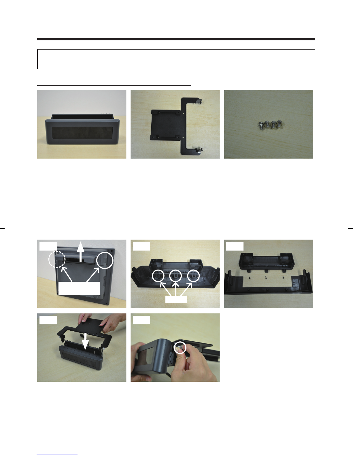
Rear Display Unit Installation
Be sure to disconnect the power cable of the main block (POS Workstation) and
confirm the power is “OFF” before the operation below.
Rear display unit (JS-960RD-020) contents
Rear display x 1 Plate x 1 Screw x 4
(1) While pushing in the cable cover release button, slide the cable cover with both hands
to remove it.
(2) Remove the three screws on the rear of the cable cover and separate it into the cable
protector and the hinge protector.
(3) Slide the plate and attach it to the rear display using the two thumbscrews.
(1)
Cable cover
release button
Screws
(3)-1 (3)-2
(2)-2(2)-1
28
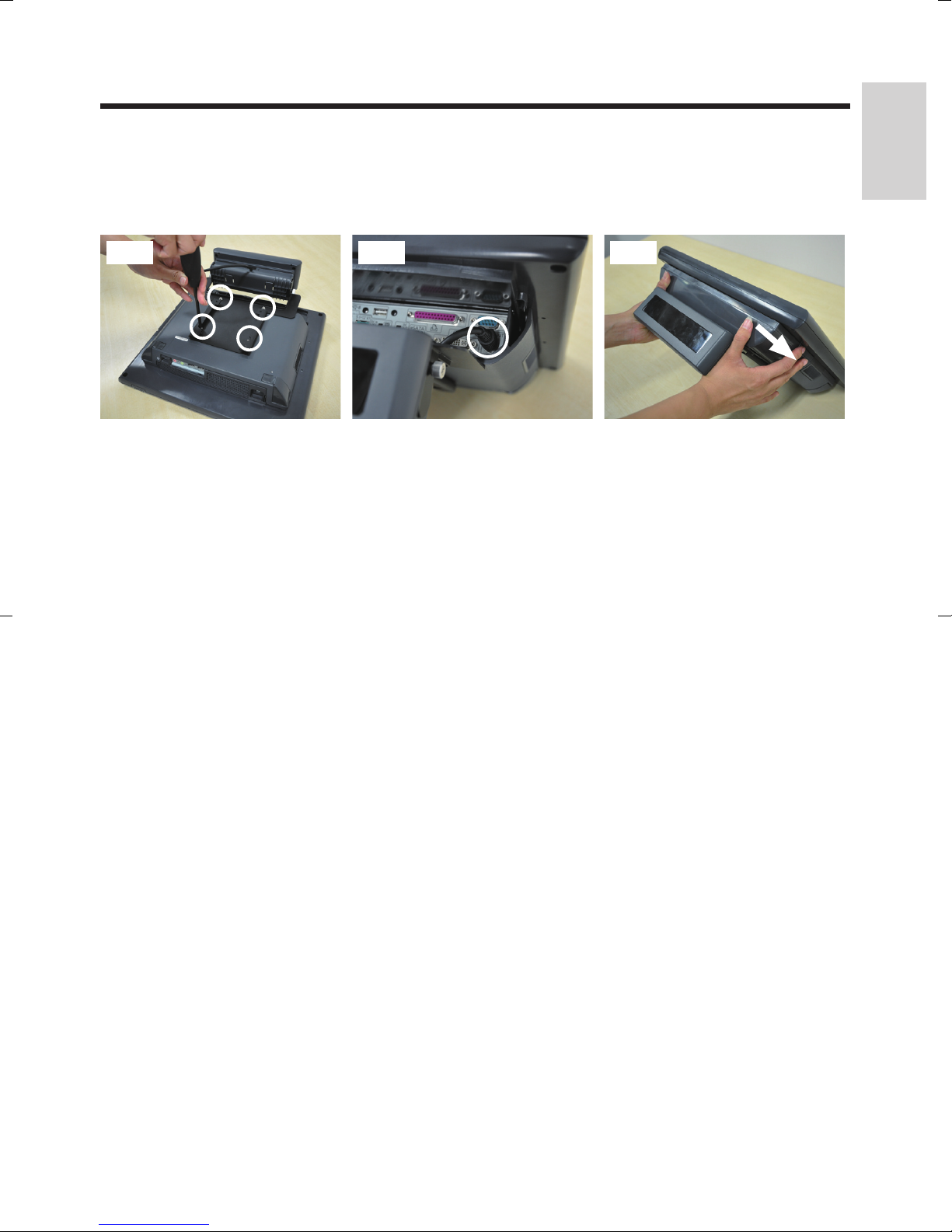
(4) Fix the rear display unit using the four screws and connect the cable to the RD OUT
connector of the main unit.
(5) Push firmly on the cable cover with both hands until it clicks to lock it into place.
(4)-1 (5)(4)-2
English
29
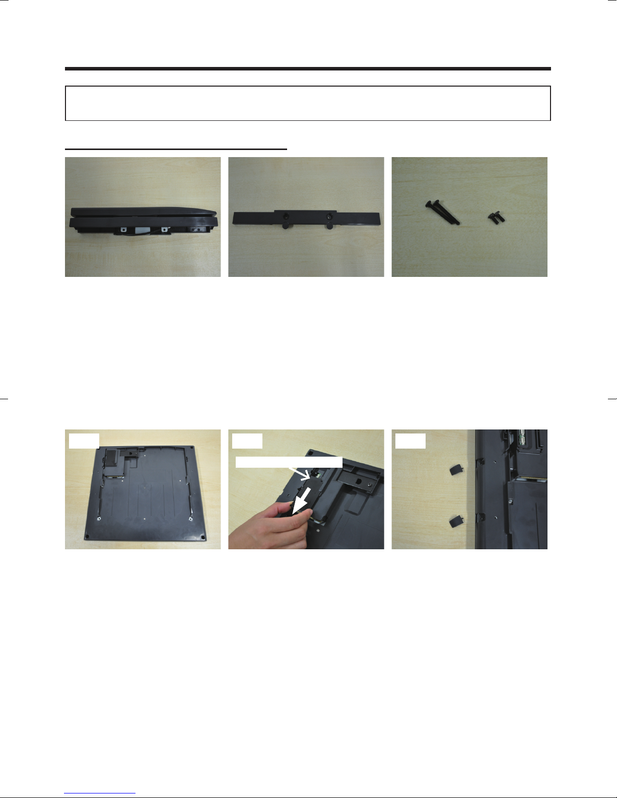
MSR Unit (Short Type) Installation
Be sure to disconnect the power cable of the main block (POS Workstation) and
confirm the power is “OFF” before the operation below.
MSR unit (JS-960MG-010) contents
MSR unit x 1 Joint x 1 Screw
large x 2, small x 2
(1) Follow steps (1) to (4) of “Display Unit Replacement” to remove the display unit.
(2) Remove the MSR connector cover.
(3) Remove the protective cover.
(1) (2) (3)
MSR connector cover
30
 Loading...