

Panasonic JS-950WS-040, JS-950D2R010, JS-950D2C010 User Manual

C
POS Workstation
User’s Manual
Model No. JS-950 Series
ontents
For USA / For CANADA / For EU / For
Russia / For Taiwan / For Korea
English
Read Me First …..………….. 6
1.Getting Started …….……..
2.Operation ……………….…
3.Appendix …………………..
Deutsch
Einführung ……….……….. 31
1.Vorbereitung ……………..
2.Betrieb …………………....
3.Anhang ……………….…..
Français
Lisez-moi d'abord …..…….. 57
1. Pour commencer ………..
2. Opération …………….…
3. Annexe …………………..
Español
Lea esto primero …..…….. 82
1. Operaciones iniciales …..
2. Operación …………….…
3. Apéndice ………………..
Русско
Сначала прочитайте …. 107
1. Начало работы …….……..
2. Эксплуатация ………….…
3. Приложение ……………..
한국어
먼저 읽어 주십시오 ….... 134
1. 시작하기 …….……..
2. 조작 ……………….…
3. 부록 …………………..
臺灣
使用前須知 …..……….. 159
1. 開始使用 …….……..
2. 操作 ……………….…
3. 附錄 …………………..

■ For USA
For USA
Federal Communications Commission Radio Frequency Interference Statement
This equipment has been tested and found to comply with the limits for a Class A digital device,
pursuant to Part 15 of the FCC Rules. These limits are designed to provide reasonable
protection against harmful interference when the equipment is operated in a commercial
environment.
This equipment generates, uses and can radiate radio frequency energy and, If not installed
and used in accordance with the instructions, may cause harmful interference to radio
communications. Operation of this equipment in a residential area is likely to cause harmful
interference in which case the user will be required to correct the interference at his own
expense.
This device complies with Part 15 of the FCC Rules. Operation is subject to the following two
conditions: (1) This device may not cause harmful interference, and (2) this device must accept
any interference received, including interference that may cause undesired operation.
Mercury caution
This product has a fluorescent lamp that contains mercury. Dispose may be regulated in your
community due to environmental considerations. For disposal or recycling information, please
contact your local authorities, or the Electronic Industries Alliance:
http://www.eiae.org
Ce produit possede une lampe fluorescente contenant du mercure. Ceci est a mettre au rebut
selon la regulation locale dans votre communaute en raison des considerations a prendre pour
la protection de l'environnement. Pour obtenir les informations relatives a la mise au rebut ou au
recyclage, veuillez prendre contact avec les autorites locales ou Electronic Industries Alliance:
http://www.eiae.org
Battery
This product contains a CR Coin Cell Lithium Battery which contains Perchlorate
Material-special handling may apply.
See www.dtsc.ca.gov/hazardouswaste/Perchlorate.
2

■ For CANADA
For CANADA
This Class A digital apparatus complies with Canadian ICES-003.
Cet appareil numérique de la classe A est conforme à la norme NMB-003 du Canada.
■ For EU
For EU
This is a class A product. In a domestic environment, this product may cause radio interference
in which case the user may be required to take adequate measures.
Importer’s name and address to follow EU rules:
Panasonic Testing Centre
Panasonic Service Europe, a division of
Panasonic Marketing Europe GmbH
Winsbergring 15, 22525 Hamburg, F. R. Germany
■ For Russia
3

■ For Korea
제품 추가 정보
1. 모델명칭(Model) : JS-950WS
2. 인증번호(Safety Approval No.) : XXXXXXXXXX
3. 제조날짜(Manufacturing Date) :
본체 밑면의 시리얼 번호를 참조하시기 바랍니다.(Please check S/N.)
yymXXXXXX
yy: 년도 표시(yy means year) (2007=07, 2008=086,…….)
m: 월 표시(m means month)
A: 1 월 B: 2 월 C: 3 월 D: 4 월 E: 5 월 F: 6 월
H: 7 월 J: 8 월 K: 9 월 L: 10 월 M: 11 월 N: 12 월
4

4. 인증 받은 자의 상호 : Panasonic Korea Ltd.
5. 제조자 및 제조국 : Matsushita Electric Industrial Co., Ltd / 일본
주의사항
Class A 급(산업용) 기기입니다.
본 제품은 산업용 전자파적합 등록 기기입니다. 본 기기를 산업용 용도 외
다른 목적으로 판매 또는 구매 시, 가정용 용도에 맞게 변경해 주시기 바랍니다.
■ For Taiwan
甲類
此設備經測試證明符號BSMI(經濟部標準檢驗局)之甲類數位裝置的限制規定。這些限制的目
的是為了在商業環境中使用此設備時,能提供合理的保護以防止有害的干擾。此設備會產生、使
用並散發射頻能量:如果未導照製造廠商的指導手冊來安裝和使用,可能會干擾無線電通訊。請
勿在住宅區使用此設備。
警告使用者:
這是甲類的資訊產品,在居住的環境中使用時,可能會造成射頻干擾,
在這種情況下,使用者會被要求采取某些適當的對策。
5
安全:電池處理
警告:新電池安裝不正解會有爆炸的危險。更換電池時,請僅使用相同或製造商建議的同
等類型電池。請勿將廢棄電池丟棄於一般垃圾中。請聯絡當地廢棄物處理機構以獲取有關最近的
廢棄電池存放站的地址。
您的電腦使用鋰幣電池。鋰幣電池為長效用電池,很有可能您永遠都不需要更換它。然而,
如果確實需要更換,請參閱您的電腦說明文件。
請勿將廢棄電池丟棄於一般垃圾中。請聯絡當地廢棄物處理機構以獲取有關最近的廢棄電
池存放站的地址。
安全:電池聲明(台灣)
廢電池請回收
6
English
Read Me First
Introduction
Thank you for purchasing the JS-950 series Panasonic POS Workstation.
This manual describes the instructions for the POS Workstation.
Please read this manual carefully before using this product.
List of JS-950 series Product
Name Model NO. Remarks
Main Block POS Workstation JS-950WS-040 CPU:3.2GHz,Memory:512MB
Touch Display Unit JS-950D2R010 12” resistive Touch screen
Display
Block
Storage
Block
ID module
Block
Rear
Display
Block
AC cord Kit
Touch Display Unit JS-950D2C010 12” capacitive Touch screen
Touch Display Unit JS-950D5R010 15” resistive Touch screen
Touch Display Unit JS-950D5C010 15” capacitive Touch screen
Storage module Unit JS-950H35010 3.5HDD module
Storage module Unit JS-950H25010 2.5HDD module
Storage module Unit JS-950H2C010 2.5HDD with CF module
Storage module Unit JS-950HCF010 Dual CF module
MSR Unit JS-950MG-010 Magnetic strip reader module
Dallas Key Reader Unit JS-950DP-010 Dallas KEY Reader module
Fingerprint Sensor Unit JS-950FS-010 Fingerprint Sensor module
Rear Display Unit JS-950RD-010 Rear Display module 2line
Rear Display Unit JS-950RD-020 Rear Display module 4line
2nd Display Unit JS-950SD-010 2nd Display module 8.4” resistive TP
AC cord kit JS-950KT-W10 AC cord kit W
AC cord kit JS-950KT-UM0 AC cord kit UM
AC cord kit JS-950KT-UH0 AC cord kit UH
AC cord kit JS-950KT-E10 AC cord kit E
AC cord kit JS-950KT-F10 AC cord kit F
AC cord kit JS-950KT-A10 AC cord kit A
AC cord kit JS-950KT-Z10 AC cord kit Z
AC cord kit JS-950KT-J10 AC cord kit J
AC cord kit JS-950KT-H10 AC cord kit H
AC cord kit JS-950KT-K10 AC cord kit K
7

1. Getting Started
■ Precautions
[ POS Workstation: JS-950 series ]
IMPORTANT
Install a socket outlet adjacent to the equipment so that it will be easily
accessible.
CAUTION
RISK OF EXPLOSION IF BATTERY IS REPLACED BY AN INCORRECT TYPE.
DISPOSE OF USED BATTERIES ACCORDING TO THE INSTRUCTIONS.
1. Avoid Radio Frequency Interference
Do not place the POS Workstation near a television or radio receiver.
2. Avoid Stacking
Do not place heavy objects on the POS Workstation.
3. Keep Small Objects Away
Do not insert paper clips or other small objects into POS Workstation.
There is the risk of heat, fire or explosion.
4. Keep Dry
There is the risk of heat, fire or explosion.
5. Do Not Disassemble the POS Workstation
Do not attempt to disassemble the POS Workstation. There is the risk of heat, fire
or explosion.
6. Do Not Touch the Plug with Wet Hands.
There is the risk of electric shock.
7. Be Certain to Plug Fully Into the Outlet.
There is the risk of electric shock or fire.
8. When Unplugging, Make Sure to Hold the Body of the Plug.
If the power strip is damaged, there is a risk of electric shock, short circuit or fire.
9. Do Not Use a Damaged Power-code or Plug.
There is the risk of electric shock or fire.
10. Clean the Dust off the Plug, Periodically.
There is the risk of heat or fire.
11. Be Certain to Plug Fully Into the Outlet.
There is the risk of electric shock or fire.
12. When Unplugging, Make Sure to Hold the Body of the Plug .
If the power strip is damaged, there is a risk of electric shock, short circuit or fire.
8

13. Do not use the POS Workstation outdoors.
This product assumes the indoor use. There is the risk of breakdown.
14. Do not put the POS Workstation on a slope and an unstable place.
It causes the injury by falling.
<NOTE>
Do not open the Rear cover and Filter cover while the POS Workstation is operating.
9
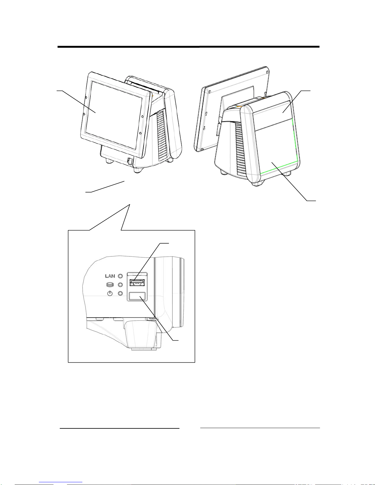
■ Name of each part & function
1
4
2
3
5
6
10

1. Operator’s Display
2. Front SW cover
3. POP Holder
4. Rear Display
5. USB connector
6. Power SW
Attention: Do not push Power SW by mistake when you insert the USB connector.
11
2. Operation
■ AC Cord Kit Installation
1. How to install the AC Cord
(1) To confirm the I/F connector on a bottom side of Main Block, lay it as shown in figure (1).
(2) Unpack the AC Cord, and then connect it to AC Inlet as shown in figure (2).
(3) Fit the Cord Clamp to AC Cord, and fix it by attached screw as shown in figure (3)-1, 2 and 3.
(4) Reawake Main Block as shown in figure (4).
(1)
AC Inlet
(3)-2 (3)-3
(2)
(3)-1
(4)
12

13

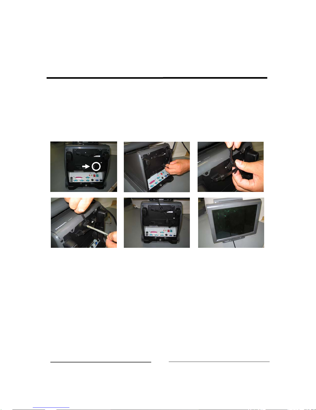
■ Display Block Installation
Be sure to disconnect the power cable of the main block (POS Workstation) and confirm
the power is “OFF” before the operation below.
1. How to install the display block
(1) Open the screw cover of the main block (POS Workstation).
(2) Hold the display block with both hands and insert the connector section of the display block
into the connector inlet guide of the main block slowly to connect the connector.
Note: When the connector section is connected, do not press the LCD surface of the display
block.
(Failure to observe this may result in damage to functions of the LCD or touch panel.)
(3) Tighten the 2 thumbscrews of the main block by hand to secure the display block.
* Make sure that no backlash is found when trying to move the display block.
* Be sure to use hand when tightening the thumbscrews.
(4) Close the screw cover of the main block.
Hold wire between the tips of one's first two fingers as shown in figure (3), and then tighten it.
(1) (2) (3)
(4)
14

2. How to replace the display block
(1) Place the main block to make the display block at right angle to the mounting table.
(2) Open the screw cover of the main block.
(3) Loosen the 2 thumbscrews securing the display block.
* The thumbscrews shall be loosened until the screws rotate without resistance.
(4) Hold the both sides of the display block and pull out the block slowly.
(5) Prepare a new display block and perform replacement in accordance with the procedure 1,
“How to mount the display block”.
15
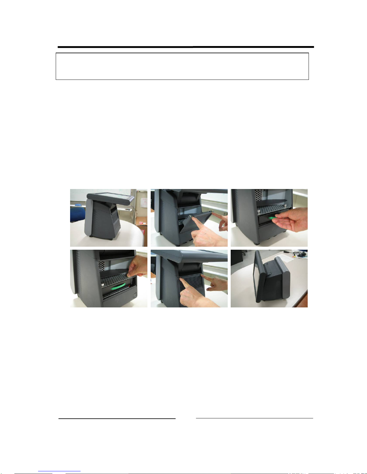
■ Storage Block Installation
Be sure to disconnect the power cable of the main block (POS Workstation) and confirm
the power is “OFF” before the operation below.
1. How to mount the storage block
(1) Disconnect the 2 latches on the upper portion of the filter cover of the main block by both
hands, pull the cover toward you while pressing the cover downward at the same time, and
remove the filter cover.
(2) Insert the storage block into the prescribed inlet of the main block slowly and connect the
connector of the main block with the connector of the storage block.
(3) Tighten the 2 thumbscrews supplied with the main block by hand to secure the storage
block.
(4) Hitch the lower portion of the filter cover to the main block, and push the cover until the
latches of both sides on the upper portion are connected to secure the cover.
(1) (2)
(3) (4)
16

2. How to replace the storage block
(1) Place the main block to make the display block in parallel with the mounting table.
(2) Disconnect the 2 latches on the upper portion of the filter cover of the main block by both
hands, pull the cover toward you while pressing the cover downward at the same time, and
remove the filter cover.
(3) Loosen the 2 thumbscrews securing the storage block by hand, hold the band on the front
side of the storage block and pull the band toward you slowly.
(4) Prepare a new storage block.
Note: Exercise care to avoid an impact on the block.
17

■ Rear Display Block Installation
Be sure to disconnect the power cable of the main block (POS Workstation) and confirm
the power is “OFF” before the operation below.
1. How to mount the rear display block
(1) Loosen the thumbscrew on the lower portion of the rear cover at the rear display side of the
main block by hand, and remove the rear cover.
* The thumbscrew shall be loosened until the screw rotates without resistance.
(2) Prepare a rear display to be used. (The contents here explain the 2-line type.)
(3) Connect the hook of the rear display to the hole of the main block, and tighten the 2
thumbscrews by hand to secure it.
(4) Connect the connector of the rear display with the connector of the main block.
* The cable shall be clamped to prevent the cable from coming out from the main block.
(5) Be care that the cable doesn't protrude beyond the case.
In case of installation of 2 line Rear Display module, clump the cable as shown in the fig.
(5)-1. In case of installation of 4 line Rear Display module, you do not need clump cable.
(6) Peel off the blind seal attached on the window of the rear cover.
(7) Attach the rear cover on the main block, and tighten the thumbscrew on the lower portion
by hand to secure the cover.
(1)-1
(3)-1
(5)-1
(1)-2
(3)-2 (4)
(5)-2
18
(2)
(7)

2. How to replace the rear display
(1) Loosen the thumbscrew on the lower portion of the rear cover of the main block by hand,
and remove the rear cover.
* The thumbscrew shall be loosened until the screw rotates without resistance.
(2) Disconnect the connector of the rear display from the connector of the main block.
(3) Loosen the 2 thumbscrews securing the rear display, and remove the rear display.
* The thumbscrews shall be loosened until the screws rotate without resistance.
(4) Prepare a new rear display.
(5) Follow the steps (3), (4) and (5) of “How to mount the rear display block”.
19
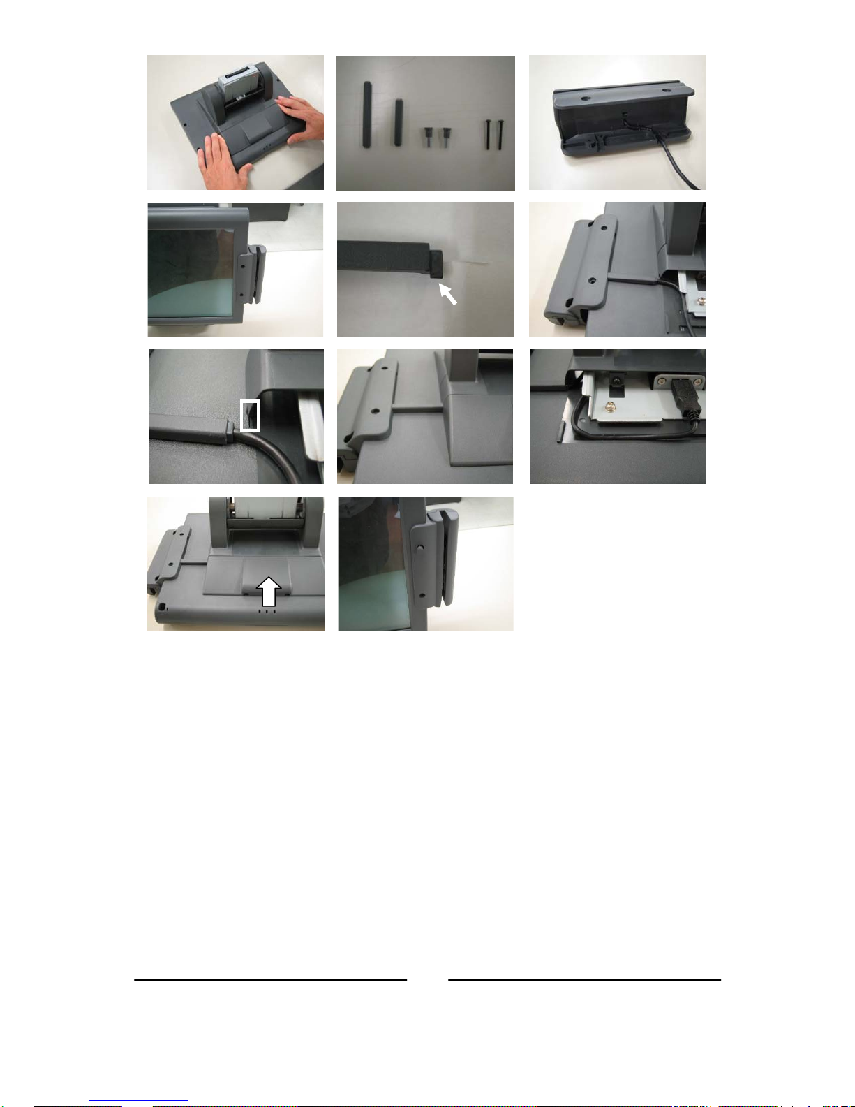
■ ID module Block installation
Be sure to disconnect the power cable of the main block (POS Workstation) and confirm
the power is “OFF” before the operation below.
1. How to mount the ID module block
(1) Place the main block to make the display block at right angle to the mounting table.
(2) Decide which side, right or left, of the display block the ID module block is mounted on.
(The contents here explain the case of the magnetic card reader mounting on the right side.)
(3) Remove Display Block. See Display Block Installation on page 6.
(4) Remove the 2 screws on the rear side of the display block using a screwdriver.
(5) Slide the USB cable cover toward you while pushing both sides of the USB cable cover at
(6) Prepare an ID module block to be mounted.
(7) Handle the cable of the ID module block (positioning and securing the cable).
(8) Put the ID module block in the position where the peripheral screws were removed on the
(9) Cable cover has direction as shown in the fig. (9)-1. Insert salient portion of Cable cover to
(10) Connect the connector of the display block with the connector of the ID module block.
Secure the cable along the guide channel on the rear side of the display block.
(11) Slide USB cable cover as shown in the fig. (11).
(12) Put the supplied 2 peripheral screws in from the front side of the ID module block and
(13) Install Display Block according to Display Block Installation P.6.
After removal of the screws, the peripheral screws can be removed from the front side of
the display block.
the hinge section of the display block inward to remove the cover.
* The ID block unit is supplied with 2 pieces of peripheral screws, 2 pieces of screws, 1
piece of long cable cover, and 1 piece of short cable cover as accessories.
・ The guide channel is provided for cable positioning and securing inside the mounting
channel of the ID module block.
・ The cable shall be run under the ID module block.
display block.
concave portion of Display block as shown in the fig. (9)-2 and (9)-3. Then completion
picture is fig. (9)-4.
tighten the screws using a screwdriver from the rear side to secure it.
(1)
(3)
(4)
20
(6)
(5)
(10)
)
(7)
(8)
(9)-3
(11)
(9)-1
Hinge cover side (salient
(9)-4
(12)
(9)-2
21

2. How to replace the ID module block
(1) Remove Display Block according to Display Block Installation.
(2) Prepare an ID module block to be used.
* The ID block unit is supplied with 2 pieces of peripheral screws, 2 pieces of screws, 1
piece of long cable cover, and 1 piece of short cable cover as accessories.
(3) Slide the USB cable cover toward you while pushing both sides of the USB cable cover at
the hinge section of the display block inward to remove the cover.
(4) Disconnect the connector of the ID module block from the connector of the main block, and
detach the cable from the guide channel.
(5) Remove the 2 screws on the rear side of the display block using a screwdriver.
After removal of the screws, the peripheral screws can be removed from the front side of
the mounted ID module block.
(6) Perform replacement in accordance with the procedure 1, “How to mount the ID module
block”.
22
3. Appendix
■ Specifications
[ Common Specifications ]
Environmental condition
Item Specification
Operating Temperature +5°C – +40°C
Operating Humidity 15% RH – 85% RH (no dew)
Strage Temperature -30°C – +60°C
Strage Humidity 10%RH – 90%RH
[ POS Workstation: JS-950WS-∗∗∗ ]
Item Specification
Power Supply input
Size
Mass
Standard
Safty
EMI &
immunity
AC100V-240V, 50/60 Hz, 6.0A
Approx. W250mm x D277mm x H351mm
Approx. 7.0 kg
cULus , IEC,EN, CCC,GOST
FCC Part15 Class A, ICES-003 Class A (Canada), CISPR22
Class A, CE(EN55022 Class A, EN55024, EN6100),
CCC Class A , GOST Class A, BSMI Class A, MIC Class A,
C-tick Class A
1: Power supply cord is not attached.
Please use the AC code kit along the safety standard in the country that sets it up.
23

IO Connector layout
(1) Bottom IO Connector layout
LAN
Printer
COM 3
(Powered)
LINE-OUT
MIC
USB4(+24V)
USB3(+12V)
○○○○○○○○○○○○○
○○○○○○○○○○○○
○○○○○
○○○○
○○○○○
○○○○
USB1
USB2
COM 1
COM 2
(2) Rear Display Connector Layout
2nd Display T/P & VFD 4 Lines
(3) Front IO Connector layout SW & LED
LAN LED
HDD LED
○○○○○
○○○○
○○○○○
○○○○
COM 4
(Powered)
(COM6)
○○○○○
○○○○○
○○○○○
C/D1
VGA
VFD 2lines (COM6)
USB #5
Soft Switch
C/D2
Power LED
24
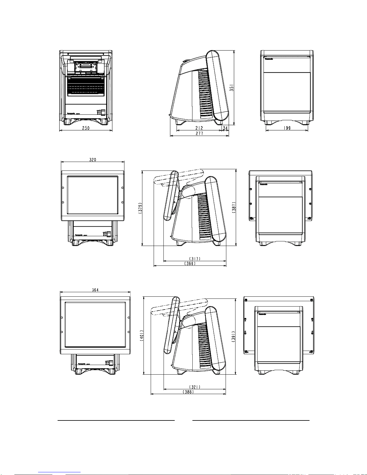
Outside drawing
Main Body
12” Touch Screen
15” Touch Screen
25

[ Touch Display Unit: JS-950D∗∗010 ]
Item Specification
Size 12.1”: Approx. W320mm x D153mm x H256mm
15”: Approx. W364mm x D153mm x H300mm
Mass 12.1”: Approx. 3.3 kg
15”: Approx. 4.2 kg
26

Outside drawing
(1) 12.1” resistive TP Display, 12.1” capacitive TP Display
(2) 15” resistive TP Display, 15” capacitive TP Display
27
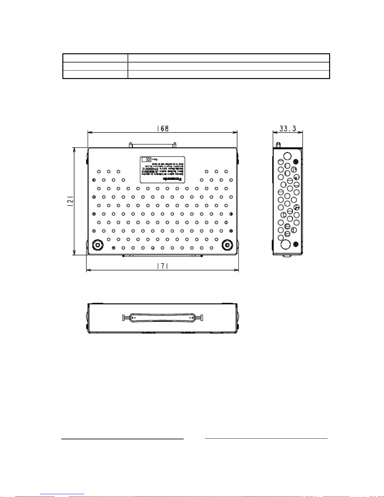
[ Storage module Unit: JS-950H∗∗∗∗∗ ]
Item Specification
Size Approx. W171mm x D126.5mm x H34mm
Mass Approx. 0.8Kg (3.5”), 0.6Kg(2.5”), 0.6Kg(2.5”+CF), 0.5Kg(2x CF)
Outside drawing
3.5HDD module, 2.5HDD module, 2.5HDD with CF module, Dual CF module
28
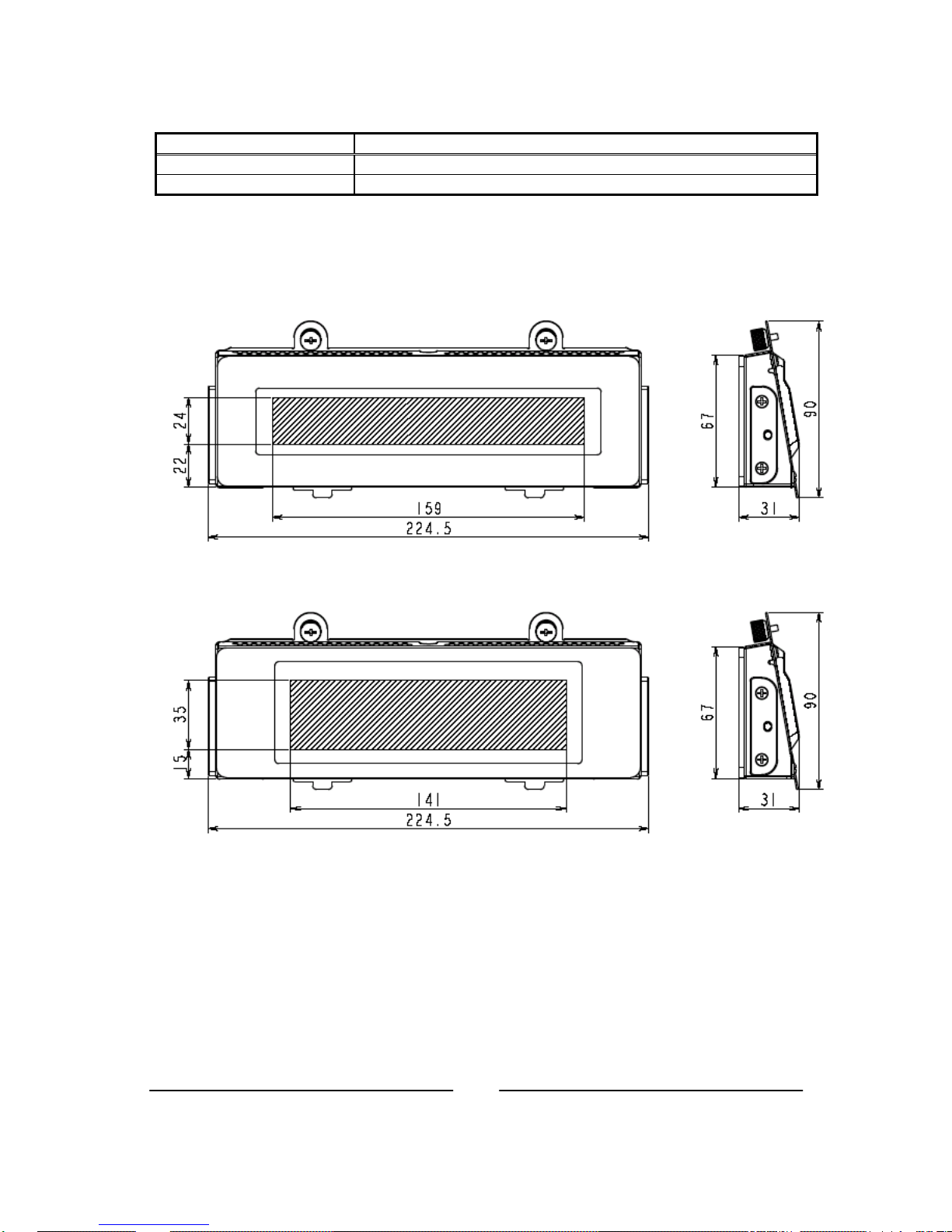
[ Rear Display Unit: JS-950RD-∗∗∗ ]
Item Specification
Size Approx. W216.5mm x D29mm x H90mm
Mass Approx. 0.4Kg (2 Lines), 0.5Kg (4Lines)
Outside drawing
Rear Display Module 2line, Rear Display Module 4line
Rear Display module 2line
Rear Display module 4line
29

Under development
[ 2nd Display Unit: JS-950SD-010 ]
Item Specification
Note: It is not possible to use it together with the Rear Display Unit.
Size Approx. W---mm x D---mm x H---mm
Mass Approx. ---kg
30
 Loading...