

Page 1
C
User’s Manual
POS Workstation
Model No. JS-950 Series
ontents
For USA / For CANADA / For EU /
For Korea / For Taiwan
English
Read Me First …..….……..... 6
1.Getting Started
2.Operation
3.Appendix
Deutsch
Einführung ……….……….. 32
1.Vorbereitung
2.Betrieb
3.Anhang
Français
Lisez-moi d'abord …..…….. 61
1. Pour commencer
2. Opération
3. Annexe
Español
Lea esto primero …..……... 88
1. Operaciones iniciales
2. Operación
3. Apéndice
Русский
Сначала прочитайте....... 115
1. Начало работы
2. Эксплуатация
3. Приложение
한국어
먼저 읽어 주십시오 …...... 144
1. 시작하기
2. 조작
3. 부록
臺灣
使用前須知 …..……....….. 170
1. 開始使用
2. 操作
3. 附錄
Before operating this product,please read the instructions carefully,
and save this manual for future use.
Page 2

■ For USA
For USA
Federal Communications Commission Radio Frequency Interference Statement
This equipment has been tested and found to comply with the limits for a Class A digital device,
pursuant to Part 15 of the FCC Rules. These limits are designed to provide reasonable
protection against harmful interference when the equipment is operated in a commercial
environment.
This equipment generates, uses and can radiate radio frequency energy and, If not installed
and used in accordance with the instructions, may cause harmful interference to radio
communications. Operation of this equipment in a residential area is likely to cause harmful
interference in which case the user will be required to correct the interference at his own
expense.
This device complies with Part 15 of the FCC Rules. Operation is subject to the following
two conditions: (1) This device may not cause harmful interference, and (2) this device
must accept any interference received, including interference that may cause undesired
operation.
Mercury caution
This product has a fluorescent lamp that contains mercury. Dispose may be regulated in your
community due to environmental considerations. For disposal or recycling information, please
contact your local authorities, or the Electronic Industries Alliance:
http://www.eiae.org
Ce produit possede une lampe fluorescente contenant du mercure. Ceci est a mettre au rebut
selon la regulation locale dans votre communaute en raison des considerations a prendre pour
la protection de l'environnement. Pour obtenir les informations relatives a la mise au rebut ou au
recyclage, veuillez prendre contact avec les autorites locales ou Electronic Industries Alliance:
http://www.eiae.org
Battery
This product contains a CR Coin Cell Lithium Battery which contains Perchlorate
Material-special handling may apply.
See www.dtsc.ca.gov/hazardouswaste/Perchlorate.
1
Page 3

■ For CANADA
For CANADA
This Class A digital apparatus complies with Canadian ICES-003.
Cet appareil numérique de la classe A est conforme à la norme NMB-003 du Canada.
■ For EU
For EU
This is a class A product. In a domestic environment, this product may cause radio interference
in which case the user may be required to take adequate measures.
Importer’s name and address to follow EU rules:
Panasonic Testing Centre
Panasonic Marketing Europe GmbH
Winsbergring 15, 22525 Hamburg, F. R. Germany
2
Page 4
■ For Korea
상호 또는 성명 : 파나소닉코리아주식회사
기기의 명칭 : POS-WORKSTATION
기본모델명 : JS-950WS-040/ JS-950WS-050
제조자/제조국가 : UNIVERSAL SCIENTIFIC INDUSTRIAL CO.,LTD./ 대만
제조날짜 : 본체 밑면의 시리얼 번호를 참조하시기 바랍니다.
yymXXXXXX
yy: 년도 표시(yy means year) (2007=07, 2008=08,.....)
m: 월 표시(m means month)
A: 1월 B: 2월 C: 3월 D: 4월 E: 5월 F: 6월
H: 7월 J: 8월 K: 9월 L: 10월 M: 11월 N: 12월
주의사항
이 기기는 업무용으로 전자파적합등록을 한 기기이오니 판매자 또는 사용자는 이 점을 주의
하시기 바라며 만약 잘못 판매 또는 구입하였을 때에는 가정용으로 교환하시기 바랍니다.
■ For Taiwan
甲類
此設備經測試證明符號BSMI(經濟部標準檢驗局)之甲類數位裝置的限制規定。這些限制的目
的是為了在商業環境中使用此設備時,能提供合理的保護以防止有害的干擾。此設備會產生、使
用並散發射頻能量:如果未導照製造廠商的指導手冊來安裝和使用,可能會干擾無線電通訊。請
勿在住宅區使用此設備。
警告使用者:
這是甲類的資訊產品,在居住的環境中使用時,可能會造成射頻干
擾,在這種情況下,使用者會被要求采取某些適當的對策。
安全:電池處理
警告:新電池安裝不正解會有爆炸的危險。更換電池時,請僅使用相同或製造商建議的同
等類型電池。請勿將廢棄電池丟棄於一般垃圾中。請聯絡當地廢棄物處理機構以獲取有關
最近的廢棄電池存放站的地址。
您的電腦使用鋰幣電池。鋰幣電池為長效用電池,很有可能您永遠都不需要更換它。然而,
如果確實需要更換,請參閱您的電腦說明文件。
請勿將廢棄電池丟棄於一般垃圾中。請聯絡當地廢棄物處理機構以獲取有關最近的廢棄電
池存放站的地址。
安全:電池聲明(台灣)
廢電池請回收
3
Page 5

Warning :
This is a class A product. In a domestic environment, this product may cause radio interference
in which case the user may be required to take adequate measures.
Warnung :
Dies ist ein Produkt der Klasse A. Wenn im Heim betrieben, kann das Produkt
Hochfrequenzstörungen verursachen, gegen die der Benutzer u.U. geeignete Maßnahmen
treffen muss.
Avertissement :
Il s'agit d'un produit de classe A. Dans un environnement privé, ce produit risque de créer des
interférences radio auquel cas des mesures correctives adéquates peuvent être exigées de la
part de l'utilisateur.
Upozornění :
Tot o j e v ýr ob ek třídy A. Ve vnitřním prostředí může tento výrobek způsobovat rádiové rušení. V
takovém případě může být požadováno, aby uživatel přijal příslušná opatření.
Advarsel :
Dette er et klasse-A produkt. I hjemmeomgivelser kan dette produkt forårsage radiostøj, i
hvilket tilfælde brugeren kan være nødsaget til at træffe fyldestgørende forholdsregler.
Предупреждение :
Это изделие класса А. В домашних условиях данное изделие может вызвать
радиопомехи, что может требовать от пользователя принятия соответствующих мер.
Varoitus :
Tämä on luokan A tuote. Kotiympäristössä tämä tuote saattaa aiheuttaa häiriöitä
radiolähetyksiin, jolloin käyttäjän tulee kenties suorittaa asianmukaiset toimenpiteet.
Advarsel :
Dette er et klasse A produkt. Ved innendørs bruk kan dette produktet forårsake radiointerferens.
I slike tilfeller kan det være nødvendig for brukeren å treffe nødvendige tiltak.
Varning :
Detta är en klass A produkt. I inomhusmiljö kan denna produkt orsaka radiostörningar. I sådant
fall åligger det användaren att vidta lämpliga åtgärder.
Upozornenie :
Toto je výrobok triedy A. Vo vnútornom prostredí môže tento výrobok spôsobovať rádiové
rušenie. V takom prípade môže byť požadované, aby používateľ prijal príslušné opatrenia.
Attenzione :
Questo è un prodotto di classe A. In ambiente domestico, questo prodotto può causare
interferenze radio, nel qual caso può essere necessario che l'utente adotti misure adeguate.
4
Page 6

Aviso :
Éste es un producto de clase A. En la instalación en una vivienda, este producto puede causar
interferencias de radio, en cuyo caso puede resultar necesario que el usuario tome medidas
pertinentes.
Waarschuwing :
Dit is een Klasse A product. In een huiselijke omgeving kan dit product radiostoring
veroorzaken, in welk geval de gebruiker verplicht kan zijn afdoende tegenmaatregelen te
nemen.
Advertência :
Este é um produto da classe A. Quando este produto for utilizado num ambiente doméstico,
poderá provocar interferências radiofónicas e, neste caso, pode ser necessário que o utilizador
tome as providências adequadas.
ﺮﻳﺬﺤﺗ :
اذــــه ﺞـــــﺗﻧﻣ ص فﻧ أ. ﻲــﻓ فورــــظﻟا ﺔـــــــــﻳﻠﺣﻣﻟا، دـــﻗ بﺑـــﺳﻳ اذــــه ﺞــــــــﺗﻧﻣﻟا دـــﻗ بﺑـــﺳﻳ ﻞﺧادـــــﺗ يوــــــﻳدار ﻲـــﻓو ﻞـــﺛﻣ ﻩذـــه ﺔــــــــﻟﺎﺣﻟا ﻰــﻠﻋ مدﺧﺗـــــــــﺳﻣﻟا
ذﺎـــــــﺧﺗا رﻳﺑادــــــــــــﺗﻟا ﺔـــــــــﻣزﻼﻟا
.
5
Page 7
English
Read Me First
Introduction
Thank you for purchasing the JS-950 series Panasonic POS Workstation.
This manual describes the instructions for the POS Workstation.
Please read this manual carefully before using this product.
List of JS-950 series Product
Name Model Number. Remarks
Main Unit POS Workstation
Display
Unit
Unit
ID module
Unit
Rear
Display
Unit
AC cord Kit AC cord kit
Touch Display Unit
Storage module Unit
MSR Unit JS-950MG-010 Magnetic stripe reader module
Dallas Key Reader Unit JS-950DP-010 Dallas KEY Reader module
Fingerprint Sensor Unit JS-950FS-010 Fingerprint Sensor module
Rear Display Unit
2nd Display Unit
JS-950WS-040 CPU:3.2GHz,Memory:512MBor1GB
JS-950WS-050 CPU:3.2GHz,Memory:2GB
JS-950D2R010 12” resistive Touch screen
JS-950D2C020 12” capacitive Touch screen
JS-950D5R010 15” resistive Touch screen
JS-950D5C010 15” capacitive Touch screen
JS-950D5C020 15” capacitive Touch screen
JS-950H35010 3.5HDD module Storage
JS-950HCF010 Dual CF module
JS-950RD-010 Rear Display module 2line
JS-950RD-020 Rear Display module 4line
JS-950SD-010 2nd Display module 8.4” resistive TP
JS-950SD-020 2nd Display module 8.4” w/o TP
JS-950KT-UH0 AC cord kit UH
JS-950KT-UM0 AC cord kit UM
JS-950KT-A10 AC cord kit A
JS-950KT-E10 AC cord kit E
JS-950KT-F10 AC cord kit F
JS-950KT-K10 AC cord kit K
JS-950KT-W10 AC cord kit W
JS-950KT-Z10 AC cord kit Z
6
Page 8

1. Getting Started
■ Precautions
[POS Workstation: JS-950 series]
IMPORTANT
Install a socket outlet adjacent to the equipment so that it will be easily
accessible.
CAUTION
RISK OF EXPLOSION IF BATTERY IS REPLACED BY AN INCORRECT TYPE.
DISPOSE OF USED BATTERIES ACCORDING TO THE INSTRUCTIONS.
1. Avoid Radio Frequency Interference
Do not place the POS Workstation near a television or radio receiver.
2. Avoid Stacking
Do not place heavy objects on the POS Workstation.
3. Keep Small Objects Away
Do not insert paper clips or other small objects into POS Workstation.
There is the risk of heat, fire or explosion.
4. Keep Dry
There is the risk of heat, fire or explosion.
5. Do Not Disassemble the POS Workstation
Do not attempt to disassemble the POS Workstation. There is the risk of heat, fire or
explosion.
6. Do Not Touch the Plug with Wet Hands.
There is the risk of electric shock.
7. Be Certain to Plug Fully Into the Outlet.
There is the risk of electric shock or fire.
8. When Unplugging, Make Sure to Hold the Body of the Plug.
If the power cord or outlet is damaged, there is a risk of electric shock, short circuit or fire.
9. Do Not Use a Damaged Power Cord or Plug.
There is the risk of electric shock or fire.
10. Clean the Dust off the Plug, Periodically.
There is the risk of heat or fire.
11. Do not use With Any Other Battery
Please use the specified battery.
CAUTION: Risk of explosion if battery is replced by an incorrect type.
Dispose of used batteries according to the instructions and local requirements.
7
Page 9

12. Do not Touch the Power-cord or Plug During a Storm.
There is the risk of electric shock or fire.
13. Do not use the POS Workstation outdoors.
This product assumes the indoor use. There is the risk of breakdown.
14. Do not put the POS Workstation on a slope or an unstable place.
This can cause damage to the unit or injury by falling.
Note:
Do not open the Rear cover and Filter cover while the POS Workstation is operating.
8
Page 10
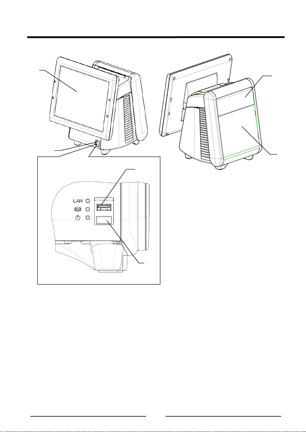
■ Name of each part & function
1
1. Operator’s Display
2. Front SW cover
3. POP Holder
4. Rear Display
5. USB connector
6. Power SW
Attention: Do not push Power SW by mistake when you insert the USB connector.
2
5
6
4
3
9
Page 11
2. Operation
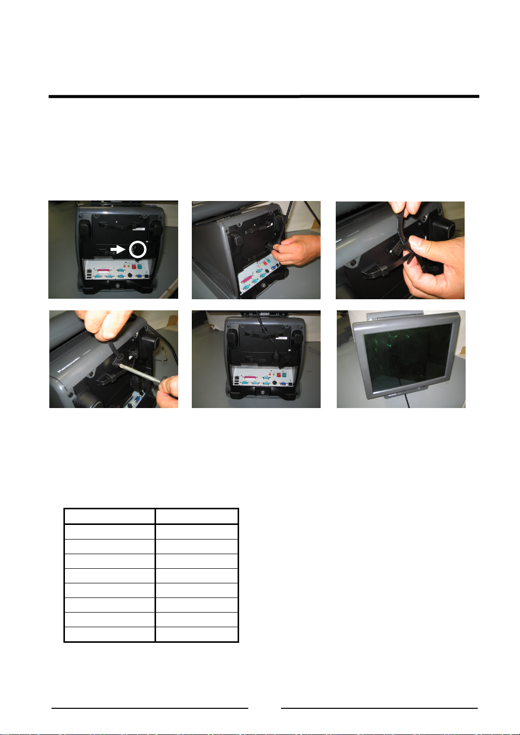
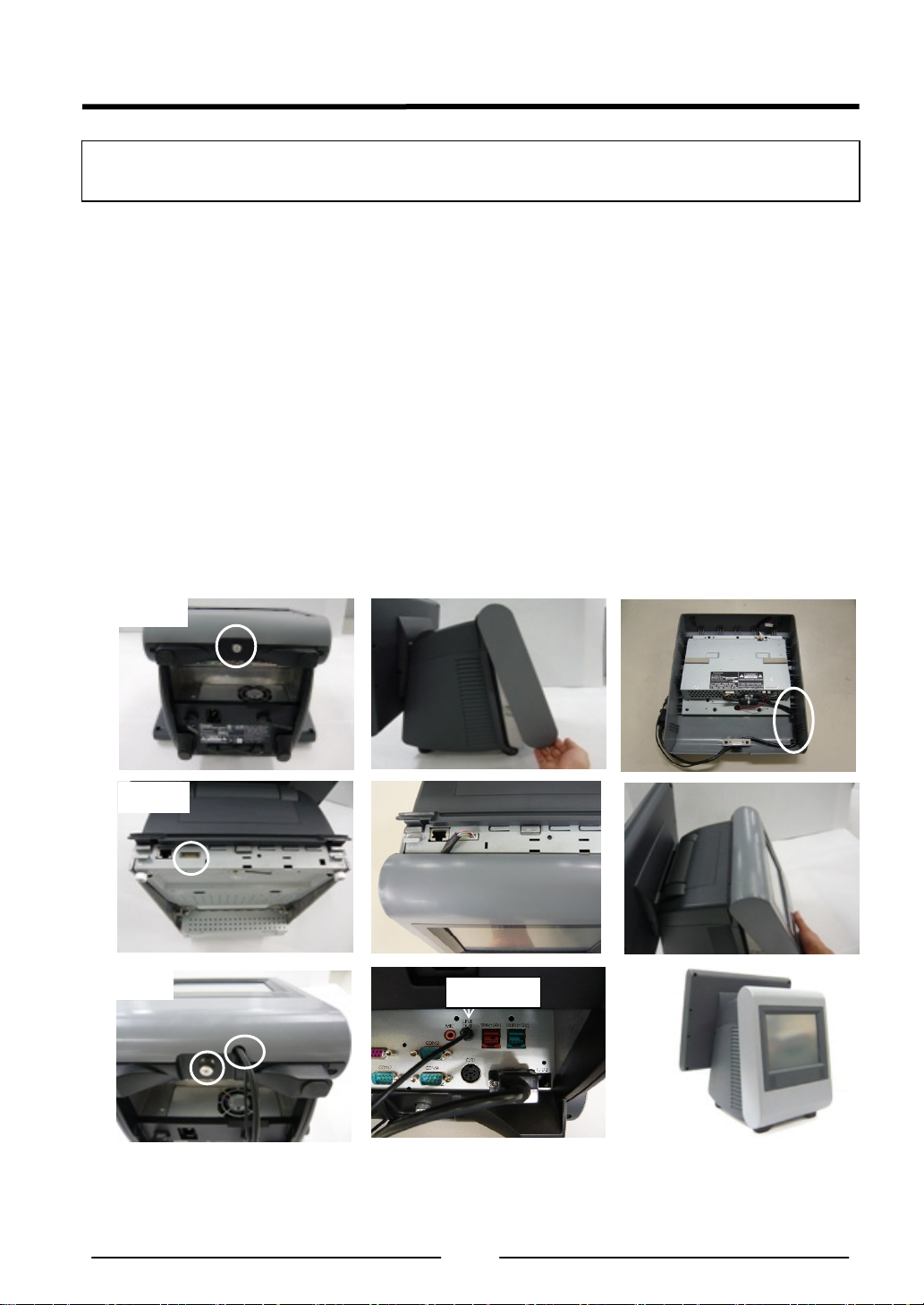
■ AC Cord Kit Installation
1. How to install the AC Cord
(1) Carefully lay the Main Body Unit on a clear, flat surface as shown in figure (1).
(2) Unpack the AC Cord, and then connect it to AC Inlet as shown in figure (2).
(3) Fit the Cord Clamp to AC Cord, and fix it by attached screw as shown in figure (3)-1, 2 and
3.
(4) Carefully replace the Main Body Unit in upright position as shown in figure (4).
(1)
AC Inlet
(3)-2 (3)-3
Note:
3 types of Clampers for fixing AC Cord are enclosed in Carton Box of Main Unit.
Select 1 type of Clamper according to diameter of AC Cord.
Confirm the AC Code doesn't move after fixing the AC Code with the clamper.
Standard Configuration List for AC Cord and Clamper
Model No. Clamper type
JS-950KT-UH0 PC-3 ø5.6
JS-950KT-UM0 PC-03C ø6.9
JS-950KT-A10 PC-3 ø5.6
JS-950KT-E10 PC-03C ø6.9
JS-950KT-F10 PC-03C ø6.9
JS-950KT-K10 PC-03C ø6.9
JS-950KT-W10 PC-03C ø6.9
JS-950KT-Z10 PC-03C ø6.9
(2)
(3)-1
(4)
10
Page 12
■ Display Unit Installation
Be sure to disconnect the power cable of the main block (POS Workstation) and confirm the
power is “OFF” before the operation below.
1. How to install the display unit
(1) Open the screw cover of the main unit (POS Workstation).
(2) Hold the display unit with both hands and insert the connector section of the display unit
into the connector inlet guide of the main unit slowly to connect the connector.
Note: When the connector section is connected, do not press the LCD surface of the
display unit.
(Failure to observe this may result in damage to functions of the LCD or touch panel.)
(3) Tighten the 2 thumbscrews of the main unit by hand to secure the display unit.
* Be sure to use hand when tightening the thumbscrews. Hold wire between the tips of
one’s first two fingers as shown in figure (3), and then tighten it.
* Make sure that no looseness is detected when trying to move the display unit.
(4) Close the screw cover of the main unit.
(1) (2) (3)
(4)
2. How to replace the display unit
(1) Place the main unit to make the display unit at right angle to the mounting table.
(2) Open the screw cover of the main unit.
(3) Loosen the 2 thumbscrews securing the display unit.
* The thumbscrews shall be loosened until the screws rotate without resistance.
(4) Hold the both sides of the display unit and pull out the unit slowly.
(5) Prepare a new display unit and perform replacement in accordance with the procedure 1,
“How to install the display unit”.
11
Page 13
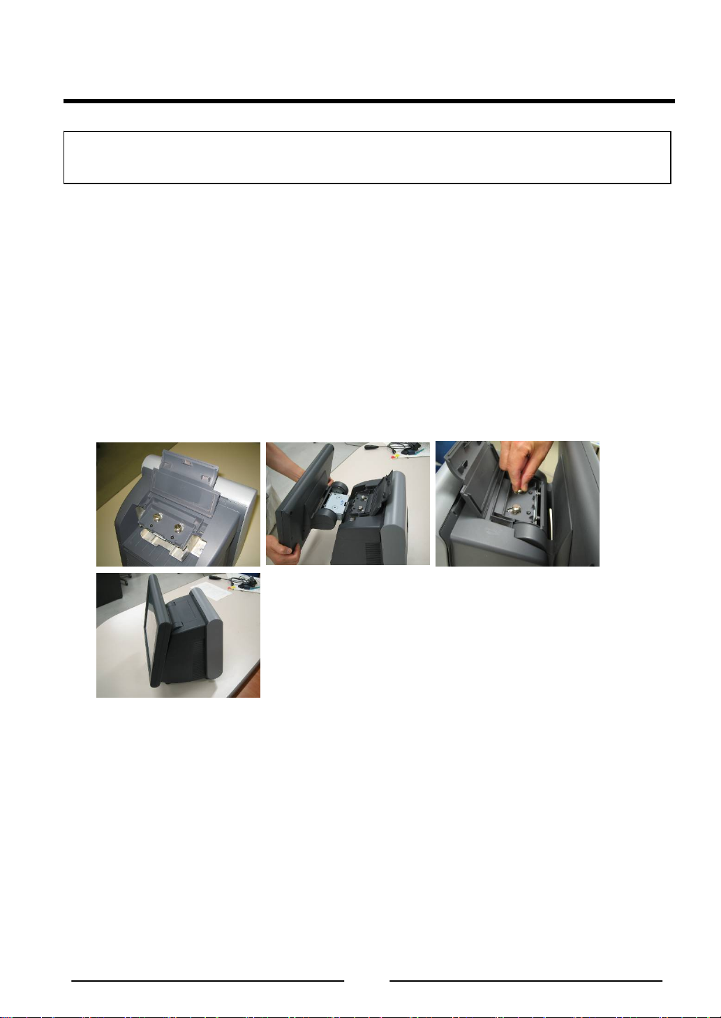
■ Storage Unit Installation
Be sure to disconnect the power cable of the main block (POS Workstation) and confirm the
power is “OFF” before the operation below.
1. How to mount the storage unit
(1) Disconnect the 2 latches on the upper portion of the filter cover of the main unit by both
hands, pull the cover toward you while pressing the cover downward at the same time, and
remove the filter cover.
(2) Insert the storage unit into the prescribed inlet of the main unit slowly and connect the
connector of the main unit with the connector of the storage unit.
(3) Tighten the 2 thumbscrews supplied with the main unit by hand to secure the storage unit.
(4) Hitch the lower portion of the filter cover to the main unit, and push the cover until the
latches of both sides on the upper portion are connected to secure the cover.
(3) (4)
2. How to replace the storage unit
(1) Place the main unit to make the display unit in parallel with the mounting table.
(2) Disconnect the 2 latches on the upper portion of the filter cover of the main unit by both
hands, pull the cover toward you while pressing the cover downward at the same time, and
remove the filter cover.
(3) Loosen the 2 thumbscrews securing the storage unit by hand, hold the band on the front
side of the storage unit and pull the band toward you slowly.
(4) Prepare a new storage unit.
Note: Exercise care to avoid any impact to the storage unit(s).
(1) (2)
12
Page 14
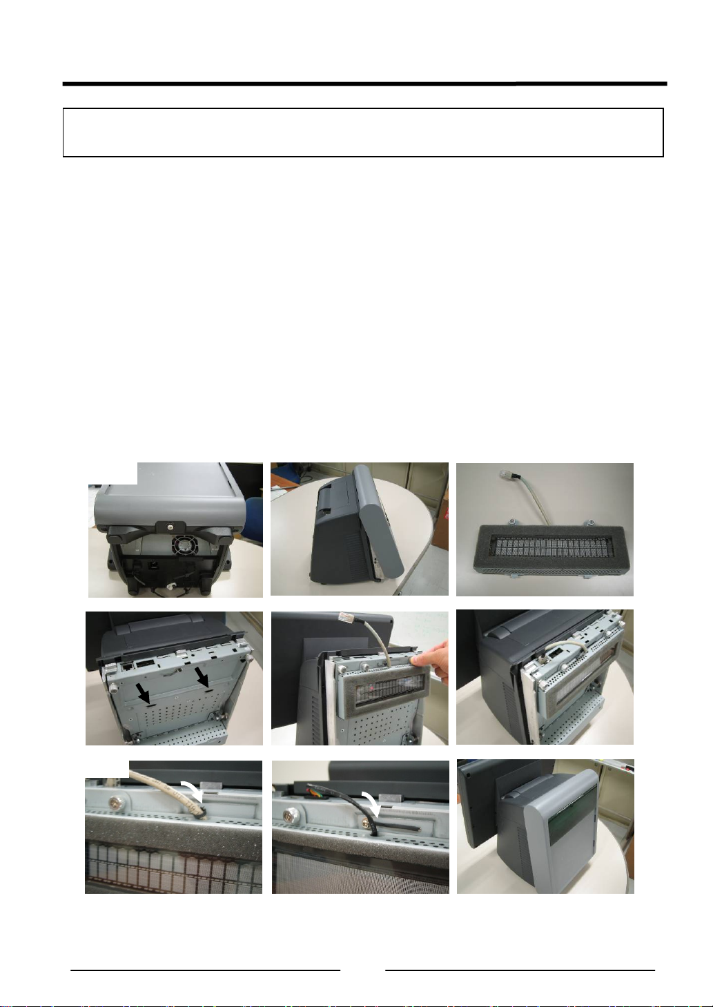
■ Rear Display Unit Installation
Be sure to disconnect the power cable of the main block (POS Workstation) and confirm the
power is “OFF” before the operation below.
1. How to mount the rear display unit
(1) Loosen the thumbscrew on the lower portion of the rear cover at the rear display side of the
main unit by hand, and remove the rear cover.
* The thumbscrew shall be loosened until the screw rotates without resistance.
(2) Prepare a rear display to be used. (The contents here explain the 2-line type.)
(3) Connect the hook of the rear display to the hole of the main unit, and tighten the 2
thumbscrews by hand to secure it.
(4) Connect the connector of the rear display with the connector of the main unit.
* The cable connector has a clip to prevent the cable from coming out from the main unit.
(5) Gently press cable toward Display Unit so that it will not extend beyond the case.
In case of installation of 2 line Rear Display module, clamp the cable as shown in the fig.
(5)-1. In case of installation of 4 line Rear Display module, you do not need to clamp cable.
(6) Peel off the blind seal attached on the window of the rear cover.
(7) Attach the rear cover on the main unit, and tighten the thumbscrew on the lower portion by
hand to secure the cover.
(1)-1
(1)-2
(2)
(3)-1
(5)-1
(3)-2 (4)
(5)-2
13
(4)-1
(7)
Page 15

2. How to replace the rear display
(1) Loosen the thumbscrew on the lower portion of the rear cover of the main unit by hand,
and remove the rear cover.
* The thumbscrew shall be loosened until the screw rotates without resistance.
(2) Disconnect the connector of the rear display from the connector of the main unit.
(3) Loosen the 2 thumbscrews securing the rear display, and remove the rear display.
* The thumbscrews shall be loosened until the screws rotate without resistance.
(4) Prepare a new rear display.
(5) Follow the steps (3), (4) and (5) of “How to mount the rear display unit”.
14
Page 16
■ 2nd display unit Installation
Be sure to disconnect the power cable of the main block (POS Workstation) and confirm the
power is “OFF” before the operation below.
1. How to mount the 2nd Display Unit
(1) Loosen the thumbscrew on the lower portion of the rear cover at the rear display side of the
main block by hand, and remove the rear cover.
* The thumbscrew shall be loosened until the screw rotates without resistance.
(2) Prepare a 2nd display unit to be used. (The contents here explain the 950SD010 type.)
Confirm the wiring that VGA Cable and Speaker Cable are put along case of inside wall as
shown in the fig. (2).
(3) Connect the connector of the 2nd display with the connector of the main block as shown in
fig. (3).
(4) Attach the rear cover on the main block as shown in fig. (4)-1. And also, route the 2nd
display’s cable (950SD010has 2 cables) in the groove as shown in fig. (4)-2. Then, tighten
the thumbscrew on the lower portion by hand to secure the cover.
(5) In case of 950SD010, connect VGA cable and speaker cable to predefined I/F on I/O
panel.
(6) Stand-up correctly.
(1)-1
(3)-1
(4)-2
(1)-2
(3)-2
(5)
LINE OUT
(2)
(4)-1
(6)
15
Page 17

2. How to replace the 2nd Display Unit
(1) In case of 950SD010, disconnect VGA cable and speaker cable from I/O panel.
(2) Loosen the thumbscrew on the lower portion of the rear cover of the main block by hand,
and remove the rear cover.
* The thumbscrew shall be loosened until the screw rotates without resistance.
(3) Disconnect the connector of the 2nd Display Unit from the connector of the main block.
(4) Prepare a new rear display.
(5) Follow the steps (3), (4) and (5) of “How to mount the 2nd Display Unit”.
16
Page 18
■ ID module Unit installation
Be sure to disconnect the power cable of the main block (POS Workstation) and confirm the
power is “OFF” before the operation below.
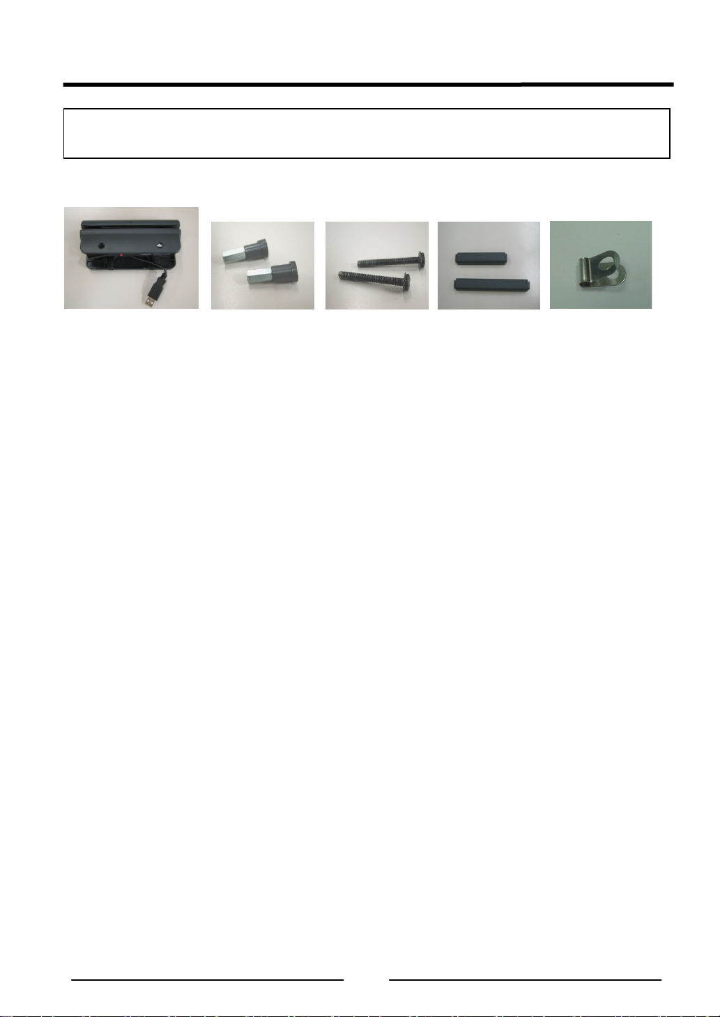
1. Contents
ID module 1pcs
Peripheral screw
2pcs
Screw 2pcs
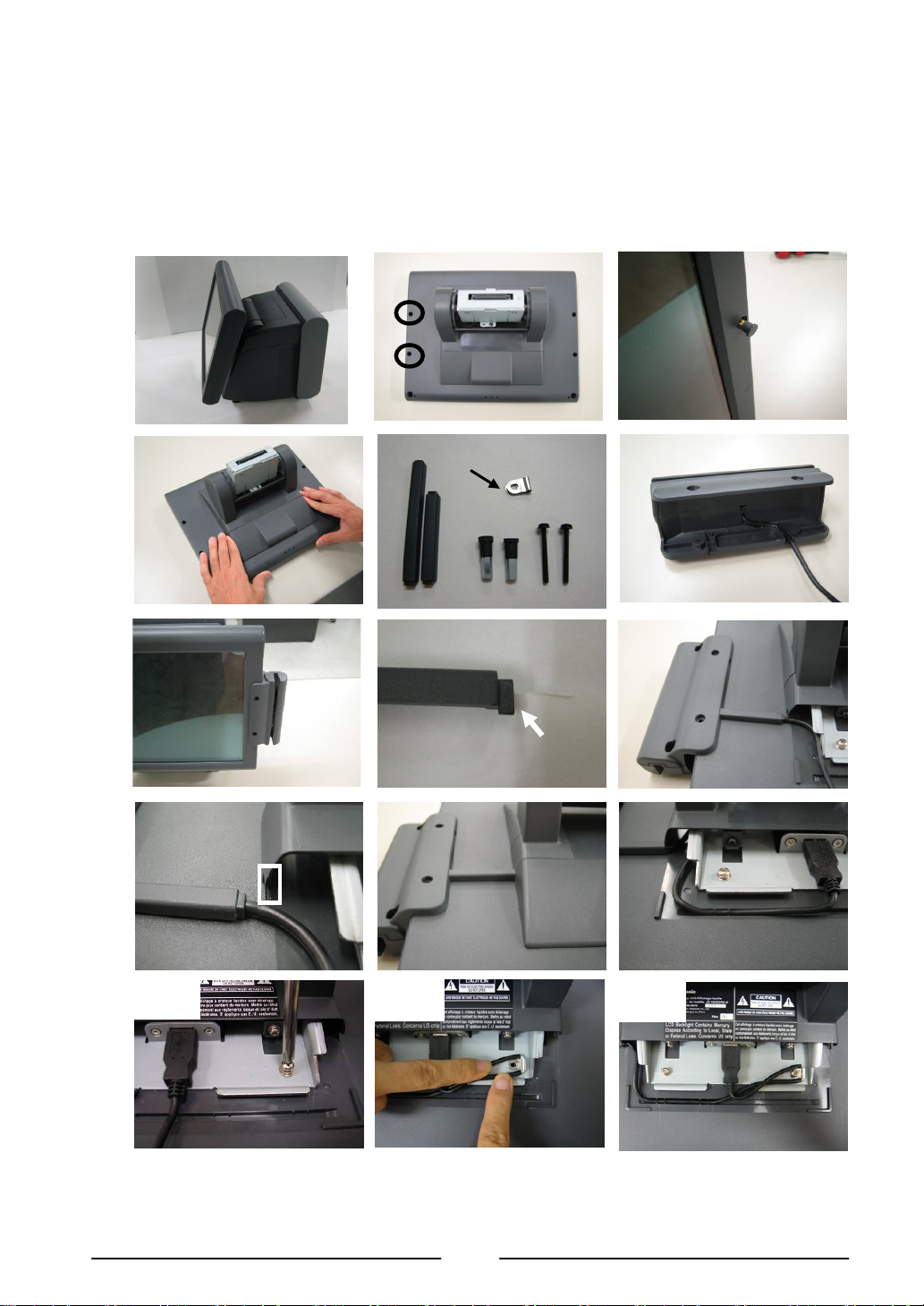
2. How to mount the ID module unit (Please see the following pictures.)
(1) Place the main unit to make the display unit at right angle to the mounting table.
(2) Decide which side, right or left, of the display unit the ID module unit is mounted on.
(The contents here explain the case of the magnetic card reader mounting on the right
side.)
(3) Remove Display Unit. See Display Unit Installation.
(4) Remove the 2 screws on the rear side of the display unit using a screwdriver.
After removal of the screws, the peripheral screws can be removed from the front side of
the display unit.
(5) Slide the USB cable cover toward you while pushing both sides of the USB cable cover at
the hinge section of the display unit inward to remove the cover.
(6) Prepare an ID module unit to be mounted.
* The ID module unit is supplied with 2 pieces of peripheral screws, 2 pieces of screws, 1
piece of long cable cover, and 1 piece of short cable cover as accessories. And Dallas
KEY reader is supplied with cable clamp
(7) Handle the cable of the ID module unit (positioning and securing the cable).
・ The guide channel is provided for cable positioning and securing inside the mounting
channel of the ID module unit.
・ The cable shall be run under the ID module unit.
(8) Put the ID module unit in the position where the peripheral screws were removed on the
display unit.
(9) Cable cover has direction as shown in the fig. (9)-1. Insert salient portion of Cable cover to
concave portion of Display unit as shown in the fig. (9)-2 and (9)-3. Then completion
picture is fig. (9)-4.
(10) In case of the magnetic card reader and fingerprint sensor, connect the connector of the
display unit with the connector of those module units.
Secure the cable along the guide channel on the rear side of the display unit as shown in
the fig. (10)-1.
In case of the Dallas KEY reader, secure the cable along the guide channel on the rear
side of the display unit. And loosen a screw as shown in the fig. (10)-2. Use clamp to clip
the ground of USB cable and put it in the position where the screw of fixing LCD hinge
were removed on the LCD hinge. (10)-3.
Cable cover
Long type 1pcs
Short type 1pcs
(Use only
Dallas KEY reader)
Cable clamp 1pcs
17
Page 19
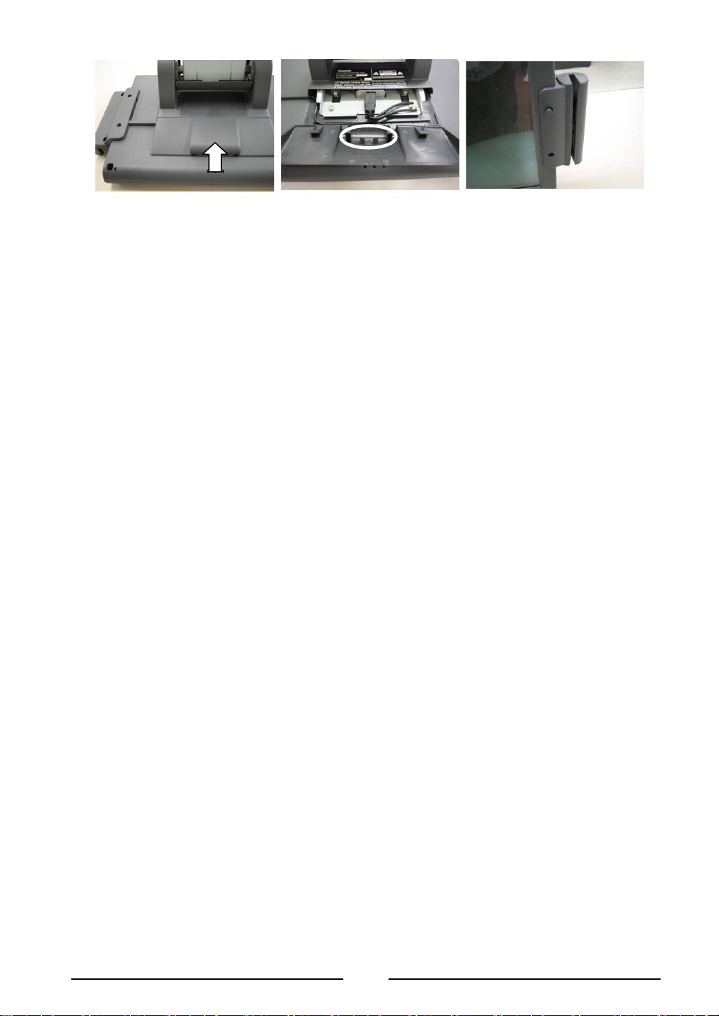
Tighten the screw to clamp the cable and wiring the cable as shown in the fig. (10)-4.
(10)
(11) Slide USB cable cover as shown in the fig. (11)-1. In case of Dallas KEY reader, slide the
USB cable cover with care to avoid the cable from the rib of the USB cable cover as shown
in the fig. (11)-2.
(12) Put the supplied 2 peripheral screws in from the front side of the ID module unit and tighten
the screws using a screwdriver from the rear side to secure it.
(13) Install Display Unit according to Display Unit Installation.
(1)
(3)
(4)
(5)
(6)
Use only
Dallas KEY reader
(7)
(8)
(9)-1
(9)-2
Hinge cover side (salient)
(9)-3
(10)-2
(9)-4
(10)-3
-1
(10)-4
18
Page 20
(11)-1
3. How to replace the ID module unit
(1) Remove Display Unit according to Display Unit Installation.
(2) Prepare an ID module unit to be used.
* The ID module unit is supplied with 2 pieces of peripheral screws, 2 pieces of screws, 1
piece of long cable cover, and 1 piece of short cable cover as accessories.
(3) Slide the USB cable cover toward you while pushing both sides of the USB cable cover at
the hinge section of the display unit inward to remove the cover.
(4) Disconnect the connector of the ID module unit from the connector of the main unit, and
detach the cable from the guide channel.
(5) Remove the 2 screws on the rear side of the display unit using a screwdriver.
After removal of the screws, the peripheral screws can be removed from the front side of
the mounted ID module unit.
(6) Perform replacement in accordance with the procedure 1, “How to mount the ID module
unit”.
(11)-2
(12)
Rib
19
Page 21
3. Appendix
■ Specifications
[Common Specifications]
Environmental condition
Item Specification
Operating Temperature +5°C – +40°C
Operating Humidity 15% RH – 85% RH (no dew)
Strage Temperature -30°C – +60°C
Strage Humidity 10%RH – 90%RH
[POS Workstation: JS-950WS-∗∗∗ ]
Item Specification
Power Supply input
Size
Mass
Standard
1: Power supply cord is not attached.
Please use the AC cord kit in accordance with safety standards in the country of use.
Safty
EMI &
immunity
AC100V-240V, 50/60 Hz, 6.0A
Approx. W250mm x D277mm x H351mm
Approx. 7.0 kg
cULus, TÜV, CE, GOST, BSMI, SABS
FCC Part15 Class A, ICES-003 Class A, CISPR22 Class A,
CE (EN55022 Class A, EN55024, EN61000), GOST Class A,
BSMI Class A, KCC Class A, C-tick Class A, SABS Class A
20
Page 22

IO Connector layout
(1) Bottom IO Connector layout
LAN
USB1
(2) Rear Display Connector Layout
(3) Front IO Connector layout SW & LED
USB2
○○○○○
○○○○
Printer
○○○○○○○○○○○○○
○○○○○○○○○○○○
○○○○○
○○○○
COM 1
2nd Display T/P & VFD 4 Lines
COM 2
LAN LED
HDD LED
Power LED
COM 3
(Powered)
○○○○○
○○○○
○○○○○
○○○○
COM 4
(Powered)
(COM6)
LINE-OUT
MIC
○○○○○
○○○○○
○○○○○
C/D1
Top of main block
VFD 2lines (COM6)
USB #5
Soft Switch
USB4(+24V)
USB3(+12V)
VGA
C/D2
21
Page 23
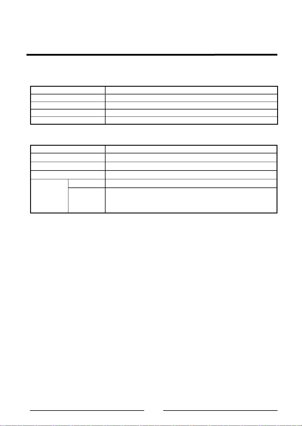
Outside drawing
Main Body
12” Touch Screen
15” Touch Screen
22
Page 24
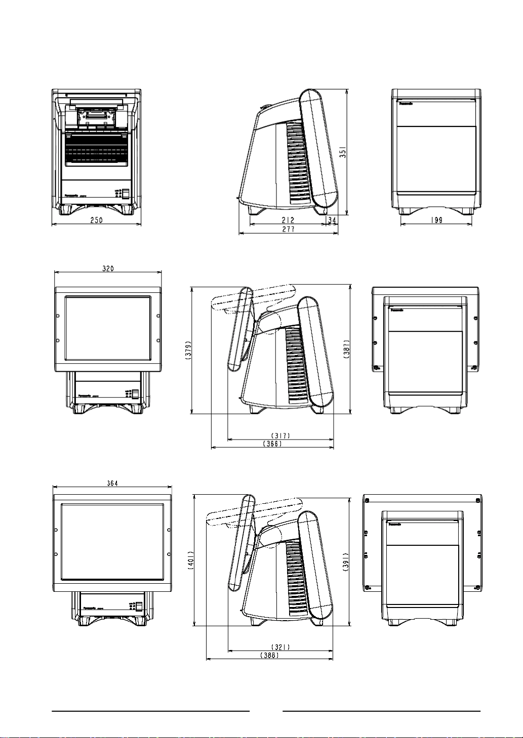
[Touch Display Unit: JS-950D∗∗∗∗∗ ]
Item Specification
Size 12.1”: Approx. W320mm x D153mm x H256mm
15”: Approx. W364mm x D153mm x H300mm
Mass 12.1”: Approx. 3.4 kg
15”: Approx. 4.4 kg
Outside drawing
(1) 12.1” resistive TP Display, 12.1” capacitive TP Display
(2) 15” resistive TP Display, 15” capacitive TP Display
23
Page 25

[Storage module Unit: JS-950H∗∗∗∗∗ ]
Item Specification
Size Approx. W171mm x D126.5mm x H34mm
Mass Approx. 0.8Kg (3.5”), 0.5Kg(2x CF)
Outside drawing
3.5HDD module, Dual CF module
24
Page 26
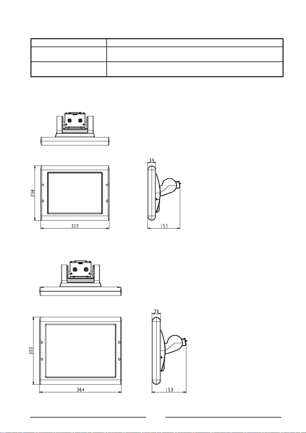
[Rear Display Unit: JS-950RD-∗∗∗ ]
Item Specification
Size Approx. W216.5mm x D29mm x H90mm
Mass Approx. 0.4Kg (2 Lines), 0.5Kg (4Lines)
Outside drawing
Rear Display Module 2line, Rear Display Module 4line
Rear Display module 2line
Rear Display module 4line
25
Page 27
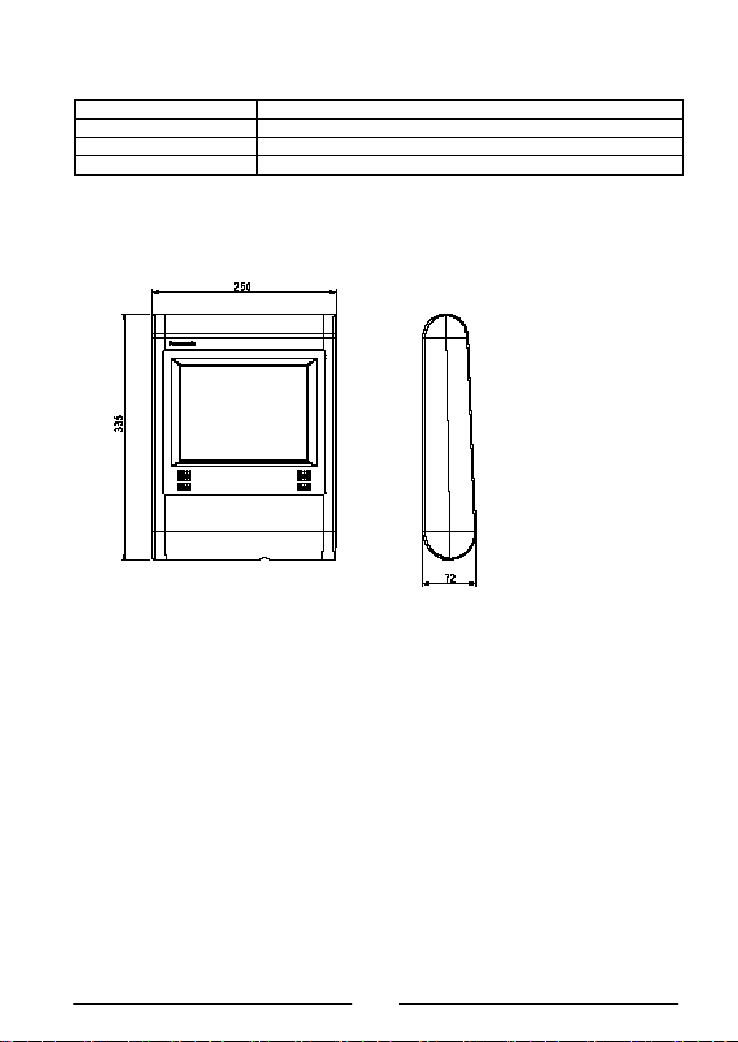
[2nd Display Unit: JS-950SD-∗∗∗ ]
Item Specification
Note: It is not possible to use it together with the Rear Display Unit.
Size Approx. W250mm x D72mm x H335mm
Mass Approx. 1.4kg
Outside drawing
26
Page 28

[MSR Unit: JS-950MG-010 ]
Item Specification
accessories
Note:
Size Approx. W63mm x D49mm x H140mm
Mass Approx. 0.1 kg
Outside drawing
2 pieces of peripheral screws
2 pieces of screws
1 piece of long cable cover
1 piece of short cable cover
MSR, Dallas Key and Fingerprint can not be used at the same
time.
27
Page 29
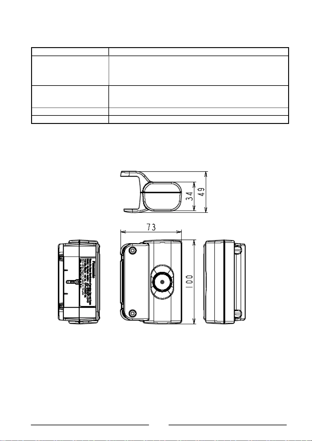
[Dallas Key Reader Unit: JS-950DP-010 ]
Item Specification
accessories
Note:
Size Approx. W73mm x D49mm x H100mm
Mass Approx. 0.15 kg
Outside drawing
2 pieces of peripheral screws
2 pieces of screws
1 piece of long cable cover
1 piece of short cable cover
- Work in virtual COM I/F
- MSR, Dallas Key and Fingerprint can not be used at the same
time.
28
Page 30
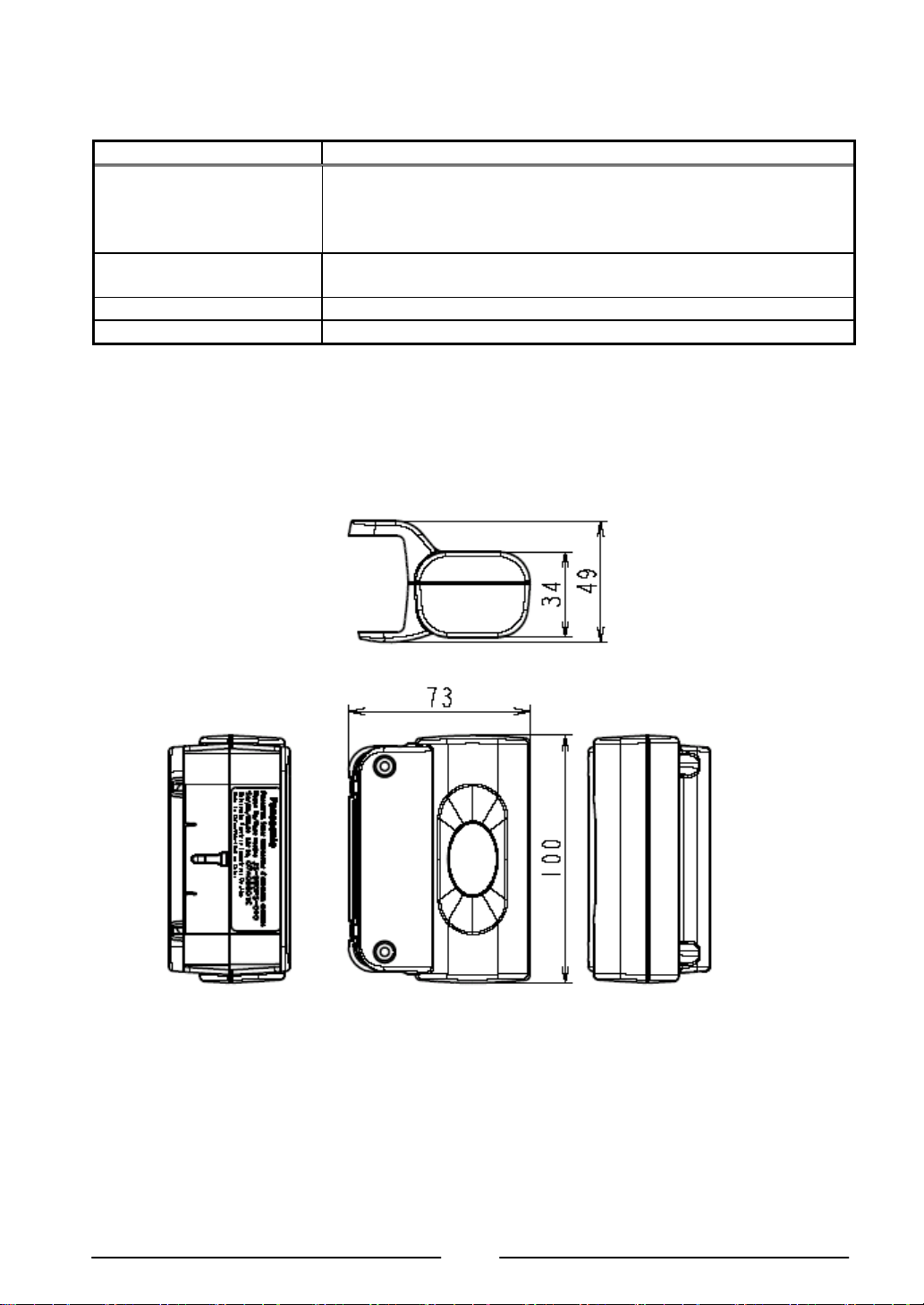
[Fingerprint Sensor Unit: JS-950FS-010 ]
Item Specification
accessories
Note:
Size Approx. W73mm x D49mm x H100mm
Mass Approx. 0.1 kg
Outside drawing
2 pieces of peripheral screws
2 pieces of screws
1 piece of long cable cover
1 piece of short cable cover
MSR, Dallas Key and Fingerprint can not be used at the same
time.
29
Page 31

■ Cleaning
Cleaning of outer case
Light soil - Wipe case lightly with a dry, soft cloth.
Heavy soil - Wipe case lightly with soft cloth pre-moistened with very diluted, mild detergent.
Lightly wipe case dry with a dry, soft cloth.
Cleaning of Display
Wipe display gently with a dry, soft cloth to remove light dirt and dust.
Do not wipe or press display hard, hit display or exert force on display as LCD in the display is
breakable.
Do not use OA Cleaner for cleaning it, because it will cause change color or change in quality.
Maintenance of outer case
Outer cases are made of plastic.
Do not apply benzine, thinner, glue, alkalinity detergent, alcohols detergent, glass cleaner, wax,
abrasive cleanser, detergent powder, or pesticide, because it will cause change color or change
in quality. (follow to the cautionary statement if chemical cloth is used.)
Do not leave rubber and vinyl product touched for a long time, because it will cause change
color or change in quality.
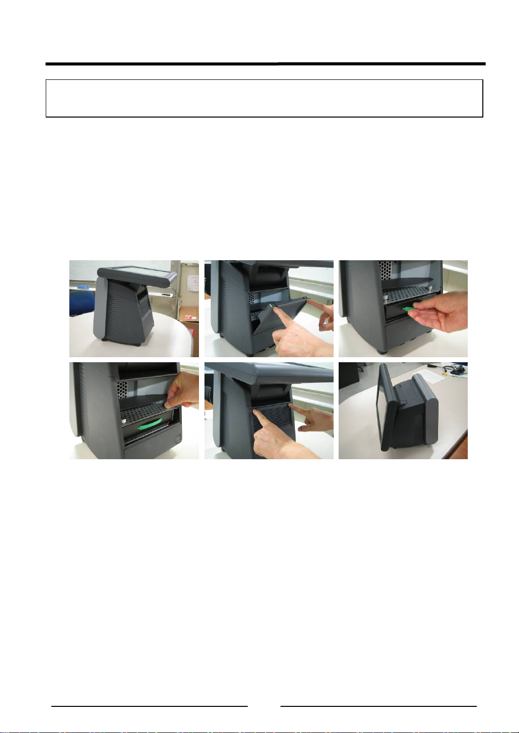
Dust filter cleaning
Clean the dust filter every month by mild detergent with the following procedure.
How to remove the dust filter.
(1) Disconnect the 2 latches on the upper portion of the filter cover of the main unit by both
hands, pull the cover toward you while pressing the cover downward at the same time, and
remove the dust filter cover.
(2) Remove the dust filter from rear side of the filter cover with pushing to direction of the
arrow in the figure (2)-1.
(3) After dust filter cleaning, reinstall it to rear side of the filter cover as shown in figure (3).
Make sure of 2 raised dots in the holes insuring the dust filter is fixed in place.
(4) Hitch the lower portion of the filter cover to the main unit, and push the cover until the
(2)-2 Dry dust filter enough after washing.
latches of both sides on the upper portion are connected to secure the cover.
(1)
(3)
(2)-1
(4)
(2)-2
30
Page 32

■ Operation
Attention for capacitive touch screen
(1) Do not touch it by finger nail, because capacitive touch screen can not recognize it. Touch
it by finger tip.
(2) Do not touch it during startup. It initializes touch screen during startup. If it is touched
during startup, touch screen is not initialized correctly.
(3) Be careful to not accidentally touch around display edges or press on display bezel as it
can negatively affect display touch sensor accuracy.
(4) Touch screen calibration can be affected by atmospheric change - typically great in
magnititude. In case of calibration shifted, perform a calibration adjustment.
(5) Adequacy of touch screen reaction-time or sensitivity may vary by operator. Display
sensitivity can be adjusted by executing a display sensitivity adjustment program*.
(6) Capacitive touch-screen panel uses radio frequency to detect finger tip touch. Terminals
are configured to use different frequencies to avoid conflict in the event of two or more
terminals operating within 1.5 meters (approx. 5') of each other. In the event of conflict
('ghost' or inexplicable touch-screen reaction(s)), shutdown and reboot the terminal to
reselect touch screen frequency.
* Inquire to the supplier about the executing display sensitivity adjustment program.
Carrying/moving terminals
Do not lift or carry the terminal by holding the Display Unit/Unit. Lift and carry the terminal by
securely holding the Main Body Unit from the bottom, with two hands.
Display angle adjustment
Take care not to place the fingers between Display and Main Unit when the angle of Display is
adjusted. Injury may occur. Adjust Display tilt-angle with two hands placed on outside, bezel
edges of Display unit.
31
Page 33

Deutsch
Einführung
Einführung
Vielen Dank, dass Sie sich für den Kauf eines Panasonic POS-Workstation der JS-950
Baureihe entschieden haben.
Dieses Handbuch beschreibt die Bedienung des POS-Workstation.
Bitte lesen Sie diese Bedienungsanweisung vor dem Gebrauch dieses Produktes sorgfältig
durch.
Liste der JS-950 Baureihe Produktes
Name Modell Nein. Bemerkungen
Hauptgerät
Block
Display Block Touchscreen Einheit
Block
ID modul Block
Hinteren display
Block
AC Schnur Kit AC Schnur kit
POS Workstation
Speichereinheit
MSR Einheit JS-950MG-010 Magnetkartenleser modul
Dallas-Schloss reader
Einheit
Fingerabdrucksensor
Einheit
Kundendisplay Einheit
2nd Display Einheit
JS-950WS-040
JS-950WS-050 CPU:3.2GHz, Arbeitsspeicher:2GB
JS-950D2R010 12” resistive Touchscreen
JS-950D2C020 12” kapazitiv Touchscreen
JS-950D5R010 15” resistive Touchscreen
JS-950D5C010 15” kapazitiv Touchscreen
JS-950D5C020 15” kapazitiv Touchscreen
JS-950H35010 3.5HDD modul Speichereinheit
JS-950HCF010 Doppel CF modul
JS-950DP-010 Dallas-Schloss reader modul
JS-950FS-010 Fingerabdrucksensor modul
JS-950RD-010 Kundendisplay modul 2 linien
JS-950RD-020 Kundendisplay modul 4 linien
JS-950SD-010 2. Displaymodul 8.4” resistive TP
JS-950SD-020 2. Displaymodul 8,4” ohne TP
JS-950KT-F10 AC Schnur kit F
JS-950KT-A10 AC Schnur kit A
JS-950KT-E10 AC Schnur kit E
JS-950KT-K10 AC Schnur kit K
JS-950KT-UH0 AC Schnur kit UH
JS-950KT-UM0 AC Schnur kit UM
JS-950KT-W10 AC Schnur kit W
JS-950KT-Z10 AC Schnur kit Z
CPU:3.2GHz, Arbeitsspeicher:512MB
oder 1GB
32
Page 34

1. Vorbereitung
■ Vorsichtsmaßnahmen
[POS Workstation: JS-950 Baureihe ]
WICHTIG
Installieren Sie eine leicht zugängliche Steckdose in unmittelbarer Nähe des
Geräts.
VORSICHT
BEI VERWENDUNG EINES FALSCHEN BATTERIETYPS BESTEHT
EXPLOSIONSGEFAHR.
ALTBATTERIEN GEMÄSS ANWEISUNG ENTSORGEN.
1. Störende Radiofrequenzen vermeiden
Den POS-Workstation nicht in der Nähe eines Fernseh- oder Radiofunkgeräts aufstellen.
2. Nicht belasten
Keine schweren Gegenstände auf den POS-Workstation legen.
3. Kleine Gegenstände fernhalten
Keine Büroklammern oder andere kleine Gegenstände in den POS-Workstation stecken.
Es besteht Erhitzungs-, Brand- und Explosionsgefahr.
4. Trocken halten
Andernfalls besteht eine Hitze-, Feuer- oder Explosionsgefahr.
5. Den POS-Workstation nicht zerlegen
Nicht versuchen den POS-workstation zu zerlegen. Es besteht Hitze-, Feuer- oder
Explosionsgefahr.
6. Den Stecker nicht mit nassen Händen berühren
Es besteht Elektroschockgefahr.
7. Darauf achten, dass der Stecker ganz in die Steckdose hineingesteckt wird.
Es besteht Elektroschock- bzw. Feuergefahr.
8. Darauf achten, dass beim Herausziehen der Stecker angefasst wird.
Wenn das Netzkabel beschädigt ist, besteht Elektroschock-, Kurzschluß- bzw.
Feuergefahr.
9. Keine beschädigten Netzkabel bzw. –stecker verwenden
Es besteht Elektroschock- bzw. Feuergefahr.
10. Staub auf dem Netzstecker regelmäßig entfernen.
Es besteht Hitze- bzw. Feuergefahr.
11. Keine anderen Batterien verwenden
Bitte verwenden Sie nur die vorgeschriebenen Batterien.
VORSICHT: Bei Verwendung eines falschen Batterietyps besteht Explosionsgefahr.
Entsorgen Sie Altbatterien gemäß den Anweisungen und örtlich geltenden Vorschriften.
33
Page 35

12. Netzkabel und –stecker bei Gewitter nicht berühren
Es besteht die Gefahr eines elektrischen Schlags.
13. POS-Workstation nicht im Freien verwenden
Das Produkt ist für den Betrieb in Innenräumen vorgesehen. Andernfalls könnte es
funktionsunfähig werden.
14. Das POS Workstation nicht auf abschüssigem oder unsicherem Untergrund
betreiben.
Es könnte herunterfallen und Verletzungen verursachen.
Hinweis:
Die hintere Abdeckung und Filterabdeckung nicht öffnen, während die Pos-Workstation
funktioniert.
34
Page 36

■ Bezeichnung und Funktion der Teile
1
1. LCD-Display
2. Front SW Abdeckung
3. POP Halter
4. VFD Abdeckung
5. USB connector
6. Power SW
Achtung: Beim Anschließen des USB-Steckverbinders nicht versehentlich den
Netzschalter drücken.
2
5
6
4
3
35
Page 37

2. Bedienung
■ Installation der Netzkabelausrüstung
1. Installieren der Netzkabelausrüstung
(1) Legen Sie das Hauptgerät gemäß Abbildung (1) auf den Rücken, damit der
Schnittstellenstecker an der Unterseite zugänglich wird.
(2) Packen Sie das Netzkabel aus und schließen Sie es dann gemäß Abbildung (2) an den
Netzanschluss an.
(3) Befestigen Sie die Kabelklemme am Netzkabel und sichern Sie sie gemäß Abbildung (3)-1,
2 und 3 mit der Schraube.
(4) Bringen Sie das Hauptgerät gemäß Abbildung (4) wieder in seine normale Lage.
(1)
Hinweis:
3 Kabelklemmentypen zum Befestigen des Netzkabels sind im Verpackungskarton des
Wählen Sie den zum Durchmesser des Netzkabels passenden Kabelklemmentyp.
Vergewissern Sie sich, dass sich das Netzkabel nach der Befestigung mit der
Zuordnung der Kabelklemmen zu den Netzkabeln
AC Inlet
(3)-2 (3)-3
Hauptgeräts enthalten.
Kabelklemme nicht mehr bewegen lässt.
Modell-Nr. Kabelklemmentyp
JS-950KT-F10 PC-03C ø6.9
JS-950KT-A10 PC-3 ø5.6
JS-950KT-E10 PC-03C ø6.9
JS-950KT-K10 PC-03C ø6.9
JS-950KT-UH0 PC-3 ø5.6
JS-950KT-UM0 PC-03C ø6.9
JS-950KT-W10 PC-03C ø6.9
JS-950KT-Z10 PC-03C ø6.9
(2)
(3)-1
(4)
36
Page 38

■ Installation des Displays
Stellen Sie vor Beginn der folgenden Arbeiten sicher, dass das Netzkabel des Hauptgeräts
(POS-Workstation) abgezogen und der Netzschalter auf “OFF” steht.
1. Befestigen des Displays
(1) Öffnen Sie die Schraubenabdeckung am Hauptgerät (POS-Workstation).
(2) Halten Sie das Display mit beiden Händen und schieben Sie den Steckverbinder des
Displays langsam in die Steckerführung des Hauptgeräts, bis die Verbindung hergesellt
ist.
Hinweis: Üben Sie beim Hineinschieben des Steckers keinen Druck auf die Oberfläche
des LCD-Displays aus.
(Andernfalls kann es zu Funktionsstörungen des LCD-Displays oder der Touchscreen
kommen.)
(3) Zum Befestigen des Displays drehen Sie die 2 Daumenschrauben am Hauptgerät mit der
Hand fest.
* Vergewissern Sie sich, dass kein Spiel vorhanden ist, indem Sie versuchen das Display
zu bewegen. Halten Sie den Leitungsdraht mit den Fingerspitzen gemäß Abbildung (3)
und befestigen Sie ihn.
* Drehen Sie die Daumenschrauben unbedingt mit der Hand fest.
(4) Schließen Sie die Schraubenabdeckung am Hauptgerät an.
2. Austauschen des Displays
(1) Positionieren Sie das Hauptgerät so auf dem Tisch, dass das Display senkrecht zum Tisch
(2) Öffnen Sie die Schraubenabdeckung am Hauptgerät.
(3) Lockern Sie die 2 Daumenschrauben, mit denen das Display befestigt ist.
* Lockern Sie die Daumenschrauben so weit, bis sie sich ohne Widerstand drehen lassen.
(4) Halten Sie das Display an beiden Seiten und ziehen Sie es langsam heraus.
(5) Stellen Sie ein neues Display bereit und führen Sie den Austausch gemäß 1. “Befestigen
(1) (2) (3)
(4)
steht.
des Displays“.
37
Page 39

■ Installation der Speichereinheit
Stellen Sie vor Beginn der folgenden Arbeiten sicher, dass das Netzkabel des Hauptgeräts
(POS-Workstation) abgezogen und der Netzschalter auf “OFF” steht.
1. Befestigen der Speichereinheit
(1) Lösen Sie die 2 Riegel oben an der Filterabdeckung des Hauptgeräts mit beiden Händen,
ziehen Sie die Abdeckung unter leichtem Druck auf sich zu und entfernen Sie sie.
(2) Setzen Sie die Speichereinheit langsam in den vorgeschriebenen Einschub im Hauptgerät
ein und verbinden Sie die Steckverbinder.
(3) Befestigen Sie die Speichereinheit mit den 2 Daumenschrauben, die dem Hauptgerät
beiliegen, indem Sie sie von Hand festdrehen.
(4) Haken Sie die Unterkante der Filterabdeckung in das Hauptgerät ein und drücken Sie sie
an, bis die beidseitig oben gelegenen Riegel einrasten und die Abdeckung gesichert ist.
(3) (4)
2. Austausch der Speichereinheit
(1) Positionieren Sie das Hauptgerät so auf dem Tisch, dass das Display parallel zum Tisch
verläuft.
(2) Lösen Sie die 2 Riegel oben an der Filterabdeckung des Hauptgeräts mit beiden Händen,
ziehen Sie die Abdeckung unter leichtem Druck auf sich zu und entfernen Sie sie.
(3) Lockern Sie die 2 Befestigungsschrauben der Speichereinheit von Hand, halten Sie das
Band an der Vorderseite der Speichereinheit und ziehen Sie es langsam auf sich zu.
(4) Stellen Sie eine neue Speichereinheit bereit.
Hinweis: Schützen Sie die Speichereinheit vor Erschütterungen.
(1) (2)
38
Page 40

■ Installation des hinteren Displays
Stellen Sie vor Beginn der folgenden Arbeiten sicher, dass das Netzkabel des
Hauptgeräts (POS-Workstation) abgezogen und der Netzschalter auf “OFF” steht.
1.Befestigen des hinteren Displays
(1) Lockern Sie die Daumenschraube unten an der rückwärtigen Abdeckung auf der
Kunden-Displayseite des Hauptgeräts von Hand und entfernen Sie die rückwärtige
Abdeckung.
* Lockern Sie die Daumenschraube so weit, bis sie sich ohne Widerstand drehen lässt.
(2) Stellen Sie ein Kunden-Display bereit. (Die Beschreibung bezieht sich auf die 2-zeilige
Anzeige.)
(3) Setzen Sie den Haken des Kunden-Displays in das Loch im Hauptgerät ein und befestigen
Sie das Display, indem Sie die 2 Daumenschrauben von Hand festdrehen.
(4) Verbinden Sie den Steckverbinder des Kunden-Displays mit dem des Hauptgeräts.
* Befestigen Sie das Kabel mit Kabelklemmen, damit es nicht aus dem Hauptgerät austritt.
(5) Ziehen Sie den Aufkleber vom Fenster in der rückwärtigen Abdeckung ab.
Bei Installation eines hinteren Displays mit 2 Linien klemmen Sie das Kabel gemäß
Abbildung (5)-1 fest. Bei Installation eines hinteren Displays mit 4 Linien ist ein
Festklemmen des Kabels nicht erforderlich.
(6) Ziehen Sie den Aufkleber vom Fenster in der rückwärtigen Abdeckung ab.
(7) Befestigen Sie die rückwärtige Abdeckung am Hauptgerät und befestigen Sie sie, indem
Sie die Daumenschraube im unteren Teil der Abdeckung von Hand festdrehen.
(1)-1
(3)-1
(5)-1
(1)-2
(3)-2 (4)
(5)-2
(2)
(7)
39
Page 41

2. Austauschen des Kunden-Displays
(1) Lockern Sie die Daumenschraube unten an der rückwärtigen Abdeckung des Hauptgeräts
von Hand und entfernen Sie die rückwärtige Abdeckung.
* Lockern Sie die Daumenschraube so weit, bis sie sich ohne Widerstand drehen lässt.
(2) Trennen Sie den Steckverbinder des Kunden-Displays von dem des Hauptgeräts.
(3) Lockern Sie die 2 Daumenschrauben, mit denen das Kunden-Display befestigt ist, und
entfernen Sie das Kunden-Display.
* Lockern Sie die Daumenschrauben so weit, bis sie sich ohne Widerstand drehen lassen.
(4) Stellen Sie ein neues Kunden-Display bereit.
(5) Führen Sie die Schritte (3), (4) und (5) unter “Befestigen des hinteren Displays” aus.
40
Page 42

■ Installation des 2. Displays
Vergessen Sie nicht, das Netzkabel vom Hauptgerät (POS-Workstation) abzuziehen und
bestätigen Sie, dass der Netzschalter auf “OFF” steht, bevor Sie folgende Arbeiten
vornehmen.
1. Befestigen der 2. Displayeinheit
(1) Lockern Sie die Daumenschraube unten an der rückwärtigen Abdeckung auf der hinteren
Displayseite des Hauptgeräts von Hand und entfernen Sie die rückwärtige Abdeckung.
* Lockern Sie die Daumenschraube so weit, bis sie sich ohne Widerstand drehen lässt.
(2) Stellen Sie ein 2. Display bereit. (Die Beschreibung bezieht sich auf den Typ 950SD010.)
Stellen Sie sicher, dass VGA-Kabel und Lautsprecherkabel gemäß Abb. (2) an der
Innenwand des Gehäuses entlang verlegt werden.
(3) Schließen Sie den Steckverbinder des 2. Displays gemäß Abb. (3) an den Steckverbinder
des Hauptgeräts an.
(4) Befestigen Sie die rückwärtige Abdeckung gemäß Abb. (4)-1 am Hauptgerät. Verlegen Sie
das Kabel des 2. Displays (950SD010 hat zwei Kabel) in der Rille gemäß Abb. (4)-2.
Sichern Sie dann die Abdeckung, indem Sie die Daumenschraube im unteren Teil der
Abdeckung von Hand festdrehen.
(5) Bei 950SD010 schließen Sie VGA-Kabel und Lautsprecherkabel an das vorher
festgelegte Z/F auf der E/A-Tafel an.
(6) Bringen Sie das Hauptgerät wieder in seine normale Lage.
(1)-1
(3)-1
(4)-2 (5)
(1)-2
(3)-2
LINE OUT
(2)
(4)-1
(6)
41
Page 43

2. Austauschen der 2. Displayeinheit
(1) Bei 950SD010 unterbrechen Sie VGA-Kabel und Lautsprecherkabel an der E/A-Tafel.
(2) Lockern Sie die Daumenschraube unten an der rückwärtigen Abdeckung des Hauptgeräts
von Hand und entfernen Sie die rückwärtige Abdeckung.
* Lockern Sie die Daumenschraube so weit, bis sie sich ohne Widerstand drehen lässt.
(3) Trennen Sie den Steckverbinder der 2. Displayeinheit von dem des Hauptgeräts.
(4) Stellen Sie ein neues hinteres Display bereit.
(5) Führen Sie die Schritte (3), (4) und (5) unter “Befestigen der 2. Displayeinheit” aus.
42
Page 44

■ Installation des ID-Moduls
Stellen Sie vor Beginn der folgenden Arbeiten sicher, dass das Netzkabel des Hauptgeräts
(POS-Workstation) abgezogen und der Netzschalter auf “OFF” steht.
1. Inhalt
ID-Modul 1 Stück
Peripherieschraube
2 Stück
Schrauben
2 Stück
Kabelabdeckung
Lange Schraube 1
Stück
Kurze Schraube 1
Stück
2. Befestigen des ID-Moduls (siehe dazu folgende Abbildungen)
(1) Positionieren Sie das Hauptgerät so auf dem Tisch, dass das Display senkrecht zum Tisch
steht.
(2) Legen Sie die Einbaulage des ID-Moduls (rechts oder links des Displays) fest.
(In der folgenden Beschreibung ist rechts das Magnetkarten-Lesegerät installiert.)
(3) Entfernen Sie das Display. Siehe Installation des Displays.
(4) Entfernen Sie die 2 Schrauben auf der Rückseite des Displays mit einem
Schraubendreher.
Nach Entfernen der Schrauben lassen sich die Peripherieschrauben an der Vorderseite
des Displays entfernen.
(5) Zum Entfernen der USB-Kabelabdeckung drücken Sie beidseitig auf die Abdeckung am
Scharnierteil des Displays und schieben sie auf sich zu.
(6) Stellen Sie ein ID-Modul bereit.
* Das ID-Modul wird mit folgendem Zubehör geliefert: 2 Peripherieschrauben, 2
Schrauben, 1 lange und 1 kurze Kabelabdeckung.
Der Dallas-Schlüsselleser wird mit
einer Kabelklemme geliefert.
(7) Verlegen und befestigen Sie das Kabel des ID-Moduls wie im Folgenden beschrieben.
・ Im Kabelkanal des ID-Moduls ist eine Kabelführung zum Verlegen und Sichern des
Kabels vorhanden.
・ Führen Sie das Kabel unter dem ID-Modul heraus.
(8) Installieren Sie das ID-Modul an der Stelle am Display, wo die Peripherieschrauben
entfernt worden sind.
(9) Positionieren Sie die Kabelabdeckung wie in Abbildung (9)-1 gezeigt. Setzen Sie den
Vorsprung an der Kabelabdeckung gemäß Abbildung (9)-2 und (9)-3 in die Aushöhlung im
Display ein. Abbildung (9)-4 zeigt die fertige Installation.
(10) Bei einem Magnetkarten- oder Fingerabdruckleser schließen Sie den Steckverbinder der
Displayeinheit an den Stecker der Moduleinheiten an.
Sichern Sie das Kabel gemäß Abb. (10)-1 entlang dem Führungskanal auf der Rückseite
der Displayeinheit.
Bei einem Dallas-KEY-Leser sichern Sie das Kabel entlang dem Führungskanal auf der
(Nur
Dallas-KEY-Leser
verwenden)
Kabelklemme 1
Stück
43
Page 45

Rückseite der Displayeinheit. Lösen Sie die in Abb. (10)-2 gezeigte Schraube. Sichern Sie
(10)
die Erdleitung des USB-Kabels mit einer Kabelklemme, die Sie am LCD-Scharnier,
dessen Befestigungsschraube entfernt wurde, befestigen. (10)-3.
Befestigen Sie das Kabel, indem Sie die Schraube anziehen, und verlegen Sie das Kabel
gemäß Abb. (10)-4.
(11) Schieben Sie die USB-Kabelabdeckung in die in Abbildung (11) gezeigte Position. Bei
einem Dallas-KEY-Leser schieben Sie die USB-Kabelabdeckung vorsichtig, um eine
Beschädigung des Kabels durch die Rippe an der USB-Kabelabdeckung zu vermeiden
(siehe Abb. (11)-2).
(12) Setzen Sie die 2 mitgelieferten Peripherieschrauben von vorne in das ID-Modul ein und
ziehen Sie die Schrauben mit einem Schraubendreher von der Rückseite her fest.
(13) Installieren Display Block nach Installation des Displays.
(1)
(5)
(8)
(3)
Nur Dallas-KEY-Leser
(6)
verwenden
(9)-1
Scharnierabdeckungsseit
e (Vorsprung)
(4)
(7)
(9)-2
(9)-3
(9)-4
-1
44
Page 46

(10)-2
(1)
(10)-3
(10)-4
(11)-1
(11)-2
(12)
Rippe
3. Austauschen des ID-Moduls
(1) Entfernen Sie das Display unter Bezugnahme auf Installation des Displays.
(2) Stellen Sie ein ID-Modul bereit.
* Das ID-Modul wird mit folgendem Zubehör geliefert: 2 Peripherieschrauben, 2
Schrauben, 1 lange und 1 kurze Kabelabdeckung.
(3) Drücken sie am Eintritt in das Display auf beide Seiten der USB-Kabelabdeckung, ziehen
Sie sie auf sich zu und entfernen Sie sie
(4) Trennen Sie den Steckverbinder des ID-Moduls vom dem des Hauptgeräts und lösen Sie
das Kabel aus dem Kabelkanal.
(5) Entfernen Sie die 2 Schrauben auf der Rückseite des Displays mit einem
Schraubendreher.
Nach Entfernen der Schrauben lassen sich die Peripherieschrauben an der Vorderseite
des installierten ID-Moduls entfernen.
(6) Beziehen Sie sich zum Austauschen des ID-Moduls auf den Abschnitt 1, “Befestigen des
ID-Moduls”.
45
Page 47

3. Anhang
■ Technische Daten
[Allgemeine Spezifikationen ]
Umweltbedingung
Stück Technische Daten
Umgebungstemperatur +5°C – +40°C
Luftfeuchtigkeit (rel.) 15% RH – 85% RH (no dew)
Lagertemperatur
Lagerfeuchtigkeit 10%RH – 90%RH
[POS Workstation: JS-950WS-∗∗∗ ]
Stück Technische Daten
CPU
Chipsatz
Arbeitss
peicher
Betriebssysteme
Anderes Disk (Optional) Extern USB FDD Schnittstellen
Kommunikation Ethernet (10BASE-T/100BASE-TX)
Expansion Slot 1 Mini PCI slot Type III
Typ Intel® Celeron D
Paket LGA775
Taktfrequenz: Celeron D 352 : 3.2GHz
Kapazität Standard: 512MB (1 DIMM slot)
Slot 2 DIMM slots, 240pin
Typ DDR2
Typ Flash Speicher BIOS
BIOS Funktion ACPI 1.0b, APM 1.2, PXE boot, USB-FDD boot,
-30°C – +60°C
Intel® 945G + ICH 7
erweiterbar auf 2GB
USB-CD ROM/DVD ROM boot, USB Flash Memory boot
Windows 2000, Windows XP (including XP Embedded)
Windows Vista, MS-DOS 6.22 English
- Hinweis: Gerätetreiber werden zur Verfügung gestellt.
Windows 98SE stützt sich nicht.
Extern USB DVD/CD-ROM Schnittstellen
- Hinweis: Wake On LAN gestützt.
- Hinweis: An Bord VGA stoppt zu arbeiten, wenn die
PCI ausdrückliche graphische Karte angebracht wird
46
Page 48

Anschlü
sse
Schalter 1 Power Schalter (Power on / off)
LED 1 Power (2 Farben: grün, rot)
Machtversorgung AC100V-240V, 50/60 Hz, 6.0A
Abmessungen Ca. W250mm x D277mm x H351mm
Gewicht Ca. 7.0 kg
Standard
1: Netzkabel wird nicht angebracht.
Den AC-Schnur-kit bitte benutzen
Seriell 4 Anschlüsse 9pin D-SUB Mann
- Hinweis: 2 Anschlüsse werden Powered.
Parallel 1 Anschluss 25pin D-SUB Frau
- Hinweis: IEEE 1824 SPP/EPP/ECP gestützt
Video 1 Anschluss 15pin D-SUB Frau
- Hinweis: Die Dual Display-Funktion wird unterstützt.
(Ausschließen MS-DOS)
LAN 1 Anschluss RJ-45
USB 2.0 2 standard USB Anschlüsse
2 Powered-USB Anschlüsse (12Vx1, 24Vx1)
1 USB Anschluss front.
Audio 1 Anschluss Line-out
1 Anschluss MIC-in
Cash Drawer 1 Anschluss 6pin DIN
1 Anschluss 6pin modular
- Hinweis: Rasen Sie on/off, indem Sie eine kurze
Periode schieben.
grün on: das Operieren Staat
Rot on: Power off Staat
1 HDD (grün)
Licht an: Zugang
1 LAN (grün)
Licht an: Send/Receive
Sicherheit
Elektromag
netische
Störfreiheit
cULus, TÜV, CE, GOST, BSMI, SABS
FCC Part15 Class A, ICES-003 Class A, CISPR22 Class A,
CE (EN55022 Class A, EN55024, EN61000), GOST Class A,
BSMI Class A, KCC Class A, C-tick Class A, SABS Class A
47
Page 49

IO Connector Anordnung
play
)
(1) Bottom IO Connector Anordnung
LAN
USB1
(2) Hinteren Display Connector Anordnung
(3) Front IO Connector Anordnung SW & LED
2. Dis
USB2
○○○○○
○○○○
Drucker
○○○○○○○○○○○○○
○○○○○○○○○○○○
○○○○○
○○○○
COM 1
einheit T/P & VFD 4 Leitungen (COM6
COM 2
LAN LED
HDD LED
Strom-LED
COM 4
(Eingeschaltet)
COM 3
(Eingeschaltet)
○○○○○
○○○○
○○○○○
○○○○
LINE-OUT
MIC
C/D1
Oberseite des Hauptgeräts
VFD 2Leitungen (COM6)
USB4(+24V)
USB3(+12V)
○○○○○
○○○○○
○○○○○
VGA
USB #5
Softswitch
C/D2
48
Page 50

Externe Darstellung
Main BodyHauptgerät
12” Touch Screen12-Zoll-Touchscreen
15” Touch Screen15-Zoll-Touchscreen
49
Page 51

[Touchscreen Einheit: JS-950D∗∗∗∗∗ ]
Stück Technische Daten
Display
Touch
Panel
ID block
Schnittst
elle
Hinge
Struktur 15“ Touchscreen kann Stelle sowohl gerader Winkel als auch
Abmessungen 12.1”: Ca. W320mm x D153mm x H256mm
Gewicht 12.1”: Ca. 3.4 kg
Typ TFT type LCD with Dual Back Light
Display Größe
/ Pixel
Farben
Helligkeit 12.1”: 400 nits (ohne touch panel)
Typ 5-wire resistive oder kapazitiv
Schnittstelle
Leben 30 Million touches oder mehr
Oberfläche Blendfreie Oberflächenbehandlung
TYP Display Block hat die Struktur, daß ID angebracht wird.
Schnittstelle
Installation Zwei Installation Eigenschaften (Right, Left)
Neigungwinkel
12.1”: 800x600 (SVGA)
15”: 1024 x 768 (XGA)
260,000 Farben oder mehr
15”: 250 nits (ohne touch panel)
Seriell
(for MSR, Dallas-Schloss oder Fingerabdrucksensor)
1 exklusives Anschluss
10 to 80 Grade
waagerechter Winkel sein.
15”: Ca. W364mm x D153mm x H300mm
15”: Ca. 4.4 kg
50
Page 52

Externe Darstellung
(1) 12.1” resistive Touchscreen, 12.1” kapazitiv Touchscreen
(2) 15” resistive Touchscreen, 15” kapazitiv Touchscreen
51
Page 53

[Speichereinheit : JS-950H∗∗∗∗∗ ]
Stück Technische Daten
Typ 1 x 3.5 typ (standard)
2x CF
Festplattengröße 40GB oder mehr
Schnittstelle 1 x SATA for HDD (2.5 typ oder 3.5 typ)
1 x 44pin IDE for CF Card
Abmessungen Ca. W171mm x D126.5mm x H34mm
Gewicht Ca. 0.8 Kg (3.5”), 0.5 Kg(2x CF)
Externe Darstellung
3.5HDD modul, Dual CF modul
52
Page 54

[Kundendisplay Einheit: JS-950RD-∗∗∗ ]
Stück Technische Daten
Display Einheit VFD
Farben
Fonts
grün
Europäisch, japanisch, koreanisch,
Simp. und Trad. Chinese
Display Größe 20 Charaktere x 2 or 4 Linien
Schnittstelle VFD 2Linien: TTL seriell
VFD 4Linien: RS-232C
Abmessungen Ca. W216.5mm x D29mm x H90mm
Gewicht Ca. 0.4 Kg (2 Lines), 0.5 Kg (4Lines)
Externe Darstellung
Kundendisplaymodul 2 Linien, Kundendisplaymodul 4 Linien
Kundendisplaymodul 2 Linien
Kundendisplaymodul 4 Linien
53
Page 55

[2. Display Einheit: JS-950SD-∗∗∗ ]
Stück Technische Daten
Typ TFT typ LCD with Back Light
Display Größe / Pixel
Helligkeit
Touch panel
8.4” 800 x 600
220 nits
Resistive typ (nur 010)
Farben 260,000 colors
Audio Stereo typ 1W x 2 (nur 010)
Hinweis Es ist nicht möglich, es zusammen mit der Kundendisplay zu
verwenden.
Abmessungen Ca. W250mm x D72mm x H335mm
Gewicht Ca. 1.4 kg
Externe Darstellung
54
Page 56

[MSR Einheit: JS-950MG-010 ]
Stück Technische Daten
Track
Schnittstelle
ISO Track 1/2/3
USB
Zubehör 2 Peripherieschrauben
2 Schrauben
1 lange Kabelabdeckung
1 kurze Kabelabdeckung
Hinweis MSR, Dallas-Schloss und Fingerabdruck können nicht
gleichzeitig benutzt werden.
Abmessungen Ca. W63mm x D49mm x H140mm
Gewicht Ca. 0.1 kg
Externe Darstellung
55
Page 57

[Dallas-Schloss Reader Einheit: JS-950DP-010 ]
Stück Technische Daten
Schnittstelle
Zubehör 2 Peripherieschrauben
Hinweis - virtueller COM Schnittstelle
Abmessungen Ca. W73mm x D49mm x H100mm
Gewicht Ca. 0.15 kg
USB
2 Schrauben
1 lange Kabelabdeckung
1 kurze Kabelabdeckung
- MSR, Dallas-Schloss und Fingerabdruck können nicht
gleichzeitig benutzt werden.
Externe Darstellung
56
Page 58

[Fingerabdrucksensor Einheit: JS-950FS-010 ]
Stück Technische Daten
Schnittstelle
Zubehör 2 Peripherieschrauben
Hinweis MSR, Dallas-Schloss und Fingerabdruck können nicht
Abmessungen Ca. W73mm x D49mm x H100mm
Gewicht Ca. 0.1 kg
Externe Darstellung
USB
2 Schrauben
1 lange Kabelabdeckung
1 kurze Kabelabdeckung
gleichzeitig benutzt werden.
57
Page 59

■ Reinigung
Reinigen des Gehäuses
Zum Reinigen ziehen Sie den Netzstecker aus der Steckdose.
Wischen Sie ihn mit einem weichen Tuch ab.
Bei hartnäckiger Verschmutzung feuchten Sie ein Tuch mit einer Lösung aus einem milden
Waschmittel und Wasser an, wringen es gut aus und wischen das Gehäuse damit ab. Wischen
Sie dann mit einem trockenen Lappen nach.
Reinigen des Displays
Falls das Display verschmutzt oder verstaubt ist, wischen Sie es mit einem weichen Tuch ab.
Verwenden Sie keine harten, scheuerndenLappen, da die Displayfläche sehr empfindlich ist.
Schützen Sie das Display vor Schlägen und starkem Druck. da das LCD im Display
zerbrechlich ist.
Verwenden Sie keinen OA-Reiniger, da dieser zu Verfärbungen und Qualitätseinbuße führt.
Pflege des Gehäuses
Die Gehäuse bestehen vorwiegend aus Kunststoff.
Benzin, Farbverdünner, Leim, alkalihaltige Waschmittel,alkoholhaltige Waschmittel,
Scheibenwischmittel , Wachs, scheuernde Reiniger, Scheuerpulver und Insektizide dürfen nicht
verwendet werden, da sie zu Verfärbungen und Qualitätseinbuße führen. (Bei Verwendung
eines chemisch imprägnierten Tuchs beachten Sie die diesem beiliegenden Anweisungen.)
Das Gehäuse darf nicht längere Zeit mit Gummi- oder Vinylprodukten in Berührung bleiben,
das dies zu Verfärbungen und Qualitätseinbuße führt.
Reinigen des Staubfilters
Reinigen Sie den Staubfilter jeden Monat nach folgendem Verfahrenmit einem milden
Waschmittel.
Ausbauen des Staubfilters
(1) Lösen Sie die 2 Riegel oben an der Filterabdeckung des Hauptgeräts mit beiden Händen,
ziehen Sie die Abdeckung unter leichtem Druck auf sich zu und entfernen Sie sie.
(2) Entfernen Sie den unter der Filterabdeckung liegenden Staubfilter, indem Sie ihn gemäß
Abbildung (2)-1 in Pfeilrichtung drücken.
(3) Nachdem Sie den Staubfilter gereinigt haben, setzen Sie ihn gemäß Abbildung (3) wieder
Zum Befestigen des Staubfilters passen Sie die zwei Vorsprünge fest in die
(4) Haken Sie die Unterkante der Filterabdeckung in das Hauptgerät ein und drücken Sie sie
(2)-2 Den Staubfilter nach der Wäsche gut trocknen lassen.
unter der Filterabdeckung ein.
entsprechenden Löcher ein und vergewissern Sie sich, dass der Filter fest sitzt.
an, bis die beidseitig oben gelegenen Riegel einrasten und die Abdeckung gesichert ist.
58
Page 60

(1)
(2)-1
(2)-2
(3)
(4)
59
Page 61

■ Bedienung
Vorsicht bei der Behandlung der kapazitiven Touchscreen
(1) Berühren Sie die Touchscreen nicht mit einem Nagel, da dieser von der Touchscreen nicht
erkannt wird. Berühren Sie die Touchscreen mit der Fingerspitze.
(2) Berühren Sie die Touchscreen nicht während des Starts. Dadurch wird die Touchscreen
beim Start initialisiert. Wird die Touchscreen während des Starts berührt, so kann sie nicht
korrekt initialisiert werden.
(3) Berühren Sie den Bereich um die Touchscreen (Umrandung) möglichst nicht, da dies die
Funktion des Sensors beeinträchtigen könnte.
(4) Bei einem Umgebungswechsel kann sich die Kalibrierung verschieben. In diesem Fall
muss neu kalibriert werden.
(5) Das Ansprechen auf Eingaben durch den Bediener kann sich verzögern. In diesem Fall
muss die Ansprechempfindlichkeit nachgestellt werden.
(6) Die kapazitive Touchscreen erfasst Fingerberührung mithilfe einer Radiofrequenz. Jedes
Terminal arbeitet mit einer anderen Frequenz, um Konflikte zu verhindern, falls mehrere
Terminals in einem Abstand von weniger als 1,5 m aufgestellt sind. Im Falle eines Konflikts
(Geistererscheinung oder ungewollte Touchscreen-Reaktionen) schalten Sie das Terminal
ab, starten es neu und wählen erneut die Frequenz.
* Zur Einstellung der Ansprechempfindlichkeit und der einzelnen Endgeräte wenden Sie
sich bitte an Ihren Fachhändler.
Transport/Umsetzen der Endgeräte
Greifen Sie die Displayfläche nicht mit der Hand. Halten Sie das Hauptgerät mit beiden
Händen.
Einstellen des Displaywinkels
Achten Sie beim Einstellen des Displaywinkels darauf, dass Sie sich nicht die Finger zwischen
dem Display und dem Hauptgerät einklemmen. Dies könnte zu Verletzungen führen.
Benutzen Sie beide Hände zum Einstellen des Displaywinkels.
60
Page 62

Français
Lisez-moi d'abord
Introduction
Nous vous remercions d'avoir fait l'achat du poste de travail des séries JS-950 Panasonic POS
Workstation.
Ce manuel d'utilisation contient les instructions du positive POS Workstation.
Veuillez lire attentivement ce manuel d'utilisation avant de faire usage de ce produit.
Liste des produits des séries de JS-950
Nom
Bloc
principal
Bloc
d'affichage
stockage
Bloc
module ID
Bloc
d'affichage
arrière
Kit de
cordon c.a.
Poste de travail POS
Workstation
Unité d'affichage à écran
tactile
Unité module de
stockage
Unité MSR JS-950MG-010 Module lecteur de gente magnétique
Unité de lecteur de clé
Dallas
Unité à capteur
d'empreinte digitale
Unité d'affichage arrière
2ème unité d'affichage
Kit de cordon c.a.
Numéro de
modèle
JS-950WS-040
JS-950WS-050 Unité centrale: 3,2GHz, Memoire: 2GB
JS-950D2R010 Écran tactile résistif de 12 pouces
JS-950D2C020 Écran tactile capacitif de 12 pouces
JS-950D5R010 Écran tactile résistif de 15 pouces
JS-950D5C010 Écran tactile capacitif de 15 pouces
JS-950D5C020 Écran tactile capacitif de 15 pouces
JS-950H35010 Module 3.5HDD Bloc de
JS-950HCF010 Double module CF
JS-950DP-010 Module de lecteur de clé Dallas
JS-950FS-010 Unité à capteur d'empreinte digitale
JS-950RD-010 Module d'affichage arrière 2 lignes
JS-950RD-020 Module d'affichage arrière 4 lignes
JS-950SD-010 2ème module d'affichage 8,4” résistif TP
JS-950SD-020 2ème module d'affichage 8,4” sans TP
JS-950KT-F10 Kit de cordon c.a. F
JS-950KT-A10 Kit de cordon c.a. A
JS-950KT-E10 Kit de cordon c.a. E
JS-950KT-K10 Kit de cordon c.a. K
JS-950KT-UH0 Kit de cordon c.a. UH
JS-950KT-UM0 Kit de cordon c.a. UM
JS-950KT-W10 Kit de cordon c.a. W
JS-950KT-Z10 Kit de cordon c.a. Z
Observations
Unité centrale: 3,2GHz, Memoire: 512MB ou
1GB
61
Page 63

1. Pour commencer
■ Mesures de précaution
[Poste de travail POS Workstation: Séries JS-950 ]
IMPORTANT:
Installer une prise de sortie à côté du matériel de sorte qu'elle soit facilement
accessible.
ATTENTION
IL Y A UN RISQUE D'EXPLOSION SI LA BATTERIE EST REMPLACÉE PAR LE
MAUVAIS TYPE DE BATTERIE.
METTRE AU REBUT LES BATTERIES USÉES SELON LES DIRECTIVES.
1. Éviter les interférences de radiofréquence
Ne pas placer le poste de travail POS Workstation près d'une télévision ou d'un récepteur
radio.
2. Éviter l'empilage
Ne rien poser sur le poste de travail POS Workstation.
3. Éloigner les petits objets
Ne pas introduire d'agrafes à papier ou de petits objets dans le poste de travail POS
Workstation.
En effet; il y a risque de dégagement de chaleur, d'incendie voire d'explosion.
4. Maintenir sec
En effet; il y a risque de dégagement de chaleur, d'incendie voire d'explosion.
5. Ne pas démonter le poste de travail POS Workstation
Ne jamais chercher à démonter le poste de travail POS Workstation. En effet; il y a risque
de dégagement de chaleur, d'incendie voire d'explosion.
6. Ne pas toucher la prise à mains nues.
En effet; il y a risque d'électrocution.
7. S'assurer que la prise d'alimentation est parfaitement enfoncée dans la prise de
sortie secteur.
En effet; il y a risque d'électrocution voire d'incendie.
8. Au moment de débrancher, saisir sans faute le bloc de la prise.
Si la gaine du cordon d'alimentation est endommagée, il existe un risque d'électrocution,
de court-circuit voire d'incendie.
9. Ne pas se servir d'un cordon d'alimentation ou d'une prise d'alimentation
endommagée.
En effet; il y a risque d'électrocution voire d'incendie.
10. Retirer régulièrement toute accumulation de poussière de la prise d'alimentation.
En effet; il y a risque de dégagement de chaleur voire d'incendie.
62
Page 64

11. Ne pas l'utiliser avec un autre type de batterie
Veiller à utiliser la batterie spécifiée.
ATENTION: Il y a un risque d'explosion si la batterie est remplacée par le mauvais type de
batterie.
Mettre les batteries au rebut conformément aux instructions et règlements locaux en
vigueur.
12. Ne pas toucher le cordon d'alimentation ni la prise d'alimentation pendant un orage.
En effet; il y a risque d'électrocution voire d'incendie.
13. Ne pas utiliser le poste de travail POS Workstation à l'extérieur.
Cet appareil est conçu pour une utilisation dans une pièce.En effet; il y a risque de panne.
14. Ne pas placer le poste de travail POS Workstation sur une surface inclinée ou
instable.
Ceci peut endommager l'appareil voire blesser quelqu'un en tombant.
Remarque:
Ne pas ouvrir pas le couvercle arrière et le couvercle du filtre alors que le poste de travail
POS Workstation est en fonctionne.
63
Page 65

■ Appellation de chaque élément et chaque fonction
1
1. Affichage opérateur
2. Couvercle frontal de commutateur
3. Support POP
4. Affichage arrière
5. Connecteur USB
6. Interrupteur d'alimentation
Attention: Ne pas appuyer sur le commutateur d'alimentation par erreur au moment
d'insérer le connecteur USB.
2
5
6
4
3
64
Page 66

2. Opération
Pri
■ Installation du kit de cordon d'alimentation secteur
1. Comment installer le cordon d'alimentation secteur
(1) Pour confirmer le connecteur I/F situé à la base inférieure du bloc principal, le disposer
comme représenté sur la figure (1).
(2) Sortir le cordon d'alimentation secteur de sa pochette, puis le connecter à la prise d'entrée
secteur comme représenté sur la figure (2).
(3) Monter la bride d'attache de cordon sur le cordon d'alimentation secteur puis le fixer avec
la vis montée comme représenté sur les figures (3)-1, 2 et 3.
(4) Remonter le bloc principal comme représenté sur la figure (4).
(1)
Remarque:
3 types de brides d'attache pour fixer le cordon d'alimentation secteur sont joints dans le
Sélectionner 1 type de bride d'attache selon le diamètre du cordon d'alimentation secteur.
Confirmer le cordon d'alimentation secteur ne bouge pas après la fixation du cordon
Liste standard de configuration pour le cordon d'alimentation secteur et la bride d'attache.
se
d'entrée
secteur
(3)-2 (3)-3
carton de l'appareil principal.
d'alimentation secteur avec la bride d'attache.
Numéro de modèle Type de bride d'attache
JS-950KT-F10 PC-03C ø6.9
JS-950KT-A10 PC-3 ø5.6
JS-950KT-E10 PC-03C ø6.9
JS-950KT-K10 PC-03C ø6.9
JS-950KT-UH0 PC-3 ø5.6
JS-950KT-UM0 PC-03C ø6.9
JS-950KT-W10 PC-03C ø6.9
JS-950KT-Z10 PC-03C ø6.9
(2)
(3)-1
(4)
65
Page 67

■ Installation du bloc d'affichage
Débrancher sans faute le câble d'alimentation du bloc principal (poste de travail POS
Workstation) et vérifier que l'alimentation est sur “OFF” avant d'effectuer les opérations
suivantes.
1. Comment installer le bloc d'affichage
(1) Ouvrir le couvercle à vis du bloc principal (poste de travail POS Workstation).
(2) Saisir le bloc d'affichage à deux mains et introduire lentement la section connecteur du
bloc d'affichage dans le guide d'introduction de connecteur du bloc principal pour
accoupler le connecteur.
Remarque: Lorsque la section de connecteur est connectée, ne pas appuyer sur la
surface de l'écran à cristaux liquides du bloc d'affichage.
(Les fonctions de l'écran à cristaux liquides ou du panneau tactile risquent d'être
endommagées si ceci n'est pas respecté.)
(3) Serrer les 2 molettes du bloc principal à la main pour bloquer fermement le bloc d'affichage
en place.
* S'assurer qu'un jeu réactif est obtenu quand une tentative de déplacement du bloc
d'affichage est faite.
* Les molettes doivent être serrées à la main.
(4) Fermer le couvercle à vis du bloc principal.
(1) (2) (3)
(4)
2. Comment remplacer le bloc d'affichage
(1) Placer le bloc principal de telle sorte que le bloc d'affichage soit placé à angle droit sur la
table d'installation.
(2) Ouvrir le couvercle à vis du bloc principal.
(3) Desserrer les 2 molettes de fixation du bloc d'affichage.
* Les molettes de fixation doivent être desserrées jusqu'à ce que les vis tournent sans
offrir de résistance.
(4) Tenir les deux côtés du bloc d'affichage et dégager lentement le bloc.
(5) Préparer un nouveau bloc d'affichage et exécuter le remplacement conformément à la
procédure 1, “Comment installer le bloc d'affichage”.
66
Page 68

■ Rangement du bloc d'affichage
Débrancher sans faute le câble d'alimentation du bloc principal (poste de travail POS
Workstation) et vérifier que l'alimentation est sur “OFF” avant d'effectuer les opérations
suivantes.
1. Comment installer le bloc de stockage
(1) Débrancher les 2 loquets de la section supérieure du couvercle de filtre du bloc principal
en agissant avec les deux mains, dégager le couvercle vers soi tout en appuyant en même
temps sur le couvercle vers le bas et retirer le couvercle de filtre.
(2) Introduire lentement le bloc d'affichage dans l'entrée prescrite du bloc principal et
accoupler le connecteur du bloc principal au connecteur de bloc de stockage.
(3) Serrer les 2 molettes fournies avec le bloc principal à la main pour bloquer fermement le
bloc de stockage.
(4) Attacher la section inférieure du couvercle de filtre au bloc principal et repousser le
couvercle jusqu'à ce que les loquets des deux côtés de la section supérieure
s'enclenchent et retiennent fermement le couvercle.
(3) (4)
2. Comment remplacer le bloc de stockage
(1) Placer le bloc principal de telle sorte que le bloc d'affichage soit parallèle à la table
d'installation.
(2) Débrancher les 2 loquets de la section supérieure du couvercle de filtre du bloc principal
en agissant avec les deux mains, dégager le couvercle vers soi tout en appuyant en même
temps sur le couvercle vers le bas et retirer le couvercle de filtre.
(3) Desserrer à la main les 2 molettes de fixation qui retiennent le bloc de stockage, tenir la
bande de la face avant du bloc de stockage et dégager la bande lentement vers soi.
(4) Préparer un nouveau bloc de stockage.
Remarque: Veiller à ne pas soumettre le bloc à des coups.
(1) (2)
67
Page 69

■ Installation du bloc d'affichage arrière
Débrancher sans faute le câble d'alimentation du bloc principal (poste de travail POS
Workstation) et vérifier que l'alimentation est sur “OFF” avant d'effectuer les opérations
suivantes.
1. Comment installer le bloc d'affichage arrière
(1) Desserrer à la main la molette de fixation de la section inférieure du couvercle arrière côté
affichage arrière du bloc principal et retirer le couvercle arrière.
* La molette de fixation doit être desserrée jusqu'à ce que la vis tourne sans offrir de
résistance.
(2) Préparer le nouvel affichage arrière à utiliser. (Ce qui suit décrit le modèle à 2 lignes.)
(3) Accoupler le crochet de l'affichage arrière dans l'orifice du bloc principal et serrer les 2
molettes du bloc principal à la main pour bloquer l'affichage en place.
(4) Accoupler le connecteur de l'affichage arrière au connecteur du bloc principal.
* Le câble doit être attaché afin d'empêcher le câble de se dégager du bloc principal.
(5) Décoller la feuille adhésive de masquage de la fenêtre du couvercle arrière.
Dans le cas de l'installation du module d'affichage arrière à 2 lignes, serrer le câble comme
représenté sur la (5)-1. Dans le cas d'une installation du module d'affichage arrière à 4
lignes, il n'est pas nécessaire de serrer le câble.
(6) Décoller la feuille adhésive de masquage de la fenêtre du couvercle arrière.
(7) Fixer le couvercle arrière au bloc principal et serrer la molette de fixation de la section
inférieure à la mais pour fixer fermement le couvercle.
(1)-1
(3)-1
(5)-1
(1)-2
(3)-2 (4)
(5)-2
(2)
(4)-1
(7)
68
Page 70

2. Comment remplacer l'affichage arrière
(1) Desserrer à la main la molette de fixation de la section inférieure du couvercle arrière du
bloc principal et retirer le couvercle arrière.
* La molette de fixation doit être desserrée jusqu'à ce que la vis tourne sans offrir de
résistance.
(2) Débrancher le connecteur de l'affichage arrière du connecteur du bloc principal.
(3) Desserrer les 2 molettes de fixation de l'affichage arrière et retirer l'affichage arrière.
* Les molettes de fixation doivent être desserrées jusqu'à ce que les vis tournent sans
offrir de résistance.
(4) Préparer un nouvel affichage arrière.
(5) Suivre les instructions des étapes (3), (4) et (5) de “Comment installer le bloc d'affichage
arrière”.
69
Page 71

(2)
(4)-1
(4)-1
(6)
■ Installation de la 2ème unité d'affichage
Débrancher sans faute le câble d'alimentation du bloc principal (poste de travail POS
Workstation) et vérifier que l'alimentation est sur “OFF” avant d'effectuer les opérations
suivantes.
1. Comment installer la 2ème unité d'affichage
(1) Desserrer à la main la molette de fixation de la section inférieure du couvercle arrière
placé du côté affichage arrière du bloc principal et retirer le couvercle arrière.
* La molette de fixation doit être desserrée jusqu'à ce que la vis tourne sans offrir de
résistance.
(2) Préparer la nouvelle unité d'affichage à utiliser. (Ce qui suit décrit le modèle 950SD010.)
Confirmer le câblage et notamment que le câble VGA et le câble de haut-parleur sont
acheminés le long de la paroi interne du boîtier suivant les indications de la fig. (2).
(3) Accoupler le connecteur de la 2ème unité d'affichage au connecteur du bloc principal
suivant les indications de la fig. (3).
(4) Fixer le couvercle arrière sur le bloc principal suivant les indications de la fig. (4)-1. Et
également, acheminer le câble de la 2ème unité d'affichage (le modèle 950SD010 a 2
câbles) dans la rainure suivant les indications de la fig. (4)-2. Puis, serrer la vis moletée
sur la partie inférieure à la main pour fixer le couvercle en place.
(5) Dans le cas du modèle 950SD010, connecter le câble VGA et le câble de haut-parleur à
I/F prédéfini sur le panneau E/S.
(6) Installer correctement.
(1)-1
(3)-1
(4)-2
(1)-2
(1)-2
(3)-2
(3)-2
(5)
SORTIE DE LIGNE
70
Page 72

2. Comment remplacer la 2ème unité d'affichage
(1) Dans le cas du modèle 950SD010, déconnecter le câble VGA et le câble de haut-parleur
du panneau E/S.
(2) Desserrer à la main la molette de fixation de la section inférieure du couvercle arrière du
bloc principal et retirer le couvercle arrière.
* La molette de fixation doit être desserrée jusqu'à ce que la vis tourne sans offrir de
résistance.
(3) Débrancher le connecteur de la 2ème unité d'affichage du connecteur du bloc principal.
(4) Préparer un affichage arrière neuf.
(5) Suivre les instructions des étapes (3), (4) et (5) de “Comment installer la 2ème unité
d'affichage”.
71
Page 73

■ Installation du bloc module ID
Débrancher sans faute le câble d'alimentation du bloc principal (poste de travail POS
Workstation) et vérifier que l'alimentation est sur “OFF” avant d'effectuer les opérations
suivantes.
1. Table des matières
Bloc module ID
1 élém.
Vis périphérique
2 élém.
Vis 2 élém.
2. Comment installer le bloc module ID (Consulter les images suivantes.)
(1) Placer le bloc principal de telle sorte que le bloc d'affichage soit placé à angle droit sur la
table d'installation.
(2) Décider de quel côté, droit ou gauche, du bloc d'affichage le bloc module ID est installé
dessus.
(Ce qui suit explique un cas d'installation du lecteur de cartes magnétiques du côté droit.)
(3) Retirer le bloc d'affichage Voir l'installation du bloc d'affichage.
(4) Retirer les 2 vis de fixation placée au dos du bloc d'affichage à l'aide d'un tournevis.
Après avoir retiré les vis, les vis périphériques peuvent être retirées de la partie antérieure
du bloc d'affichage.
(5) Faire coulisser le couvercle de câble USB vers soi tout en repoussant les deux côtés du
couvercle de câble USB de la section de charnière du bloc d'affichage vers l'intérieur pour
retirer le couvercle.
(6) Préparer un bloc module ID à installer.
* Le bloc module ID est fourni avec 2 vis périphériques, 2 vis, 1 couvercle de câble long et
1 couvercle court de câble comme accessoires. Et le lecteur clé Dallas est fourni avec
une attache de câble.
(7) Manipulation du câble du bloc module ID (positionnement et et fixation du câble).
・ Le canal de guidage est fourni pour le positionnement du câble et la fixation à l'intérieur
du canal d'installation du bloc module ID.
・ Le câble doit passer sous le bloc module ID.
(8) Placer le bloc module ID dans la position où les vis périphériques ont été retirées sur le
bloc d'affichage.
(9) Le couvercle de câble a le sens indiqué sur la figure (9)-1. Insérer la partie saillante du
couvercle de câble dans la section concave du bloc d'affichage comme représenté sur les
figures (9)-2 et (9)-3. Ensuite, l'illustration d'accomplissement est la figure (9)-4.
(10) Dans le cas d'un lecteur de cartes magnétiques et d'un détecteur d'empreinte digitale,
brancher le connecteur de l'unité d'affichage au connecteur de ces ensembles de module.
Fixer fermement le câble le long du canal de guidage placé au dos de l'unité d'affichage
suivant les indications de la fig. (10)-1.
Couvercle de câble
Type long 1 élém.
Type court 1 élém.
(Utiliser uniquement
Module de lecteur de clé
Dallas)
Attache de câble 1 élém.
72
Page 74

Dans le cas du Lecteur de clé Dallas, fixer fermement le câble le long du canal de guidage
(10)
placé au dos de l'unité d'affichage. Et desserrer une vis suivant les indications de la fig.
(10)-2. Utiliser la bride d'attache pour saisir la masse du câble USB et pour la mettre en
position là où la vis de fixation de la charnière de l'affichage à cristaux liquides a été retirée
sur la charnière de l'affichage à cristaux liquides. (10)-3.
Serrer la vis pour maintenir le câble en place et faire le câblage du câble suivant les
indications de la fig. (10)-4.
(11) Faire coulisser le couvercle de câble USB comme représenté sur la figure (11).
Dans le cas du lecteur de clé Dallas, faire coulisser le couvercle de câble USB avec soin
pour éviter le câble de la nervure du couvercle de câble USB suivant les indications de la
fig. (11) - 2.
(12) Placer les 2 vis périphériques fournies dedans de la partie antérieure du bloc module ID et
serrer les vis à l'aide d'un tournevis du dos pour le fixer.
(13) Monter le bloc d'affichage selon les instructions d'installation du bloc d'affichage.
(1)
(5)
(8)
(1)
(3)
(6)
Utiliser uniquement
Module de lecteur de
clé Dallas
(9)-1
Côté couvercle de charnière
(saillant)
(4)
(7)
(9)-2
(9)-3
(9)-4
-1
73
Page 75

(10)-2
(10)-3
(10)-4
(11)-1
(11)-2
(12)
Nervure
3. Comment remplacer le bloc module ID
(1) Retirer le bloc d'affichage selon les instructions d'installation du bloc d'affichage.
(2) Préparer un bloc module ID à utiliser.
* Le bloc module ID est fourni avec 2 vis périphériques, 2 vis, 1 couvercle de câble long et
1 couvercle court de câble comme accessoires.
(3) Faire coulisser le couvercle de câble USB vers soi tout en repoussant les deux côtés du
couvercle de câble USB de la section de charnière du bloc d'affichage vers l'intérieur pour
retirer le couvercle.
(4) Débrancher le connecteur de bloc module ID du connecteur du bloc principal et fixer le
câble à partir du canal de guidage.
(5) Retirer les 2 vis de fixation placée au dos du bloc d'affichage à l'aide d'un tournevis.
Après avoir retiré les vis, les vis périphériques peuvent être retirées de la partie antérieure
du bloc module ID installé.
(6) Exécuter le remplacement conformément à la procédure 1, “ Comment installer le bloc
module ID”.
74
Page 76

3. Annexe
■ Caractéristiques techniques
[Caractéristiques techniques communes]
Conditions environnement
Rubrique Caractéristiques techniques
Température ambiante
de service
Humidité ambiante de
service
Température ambiante
de stockage
Humidité ambiante de
stockage
[Poste de travail POS Workstation: JS-950WS-∗∗∗ ]
Rubrique Caractéristiques techniques
Entrée d'alimentation
Taille
Poids
Normes
1: Le cordon d'alimentation secteur n'est pas joint.
Veuillez utiliser le kit de cordon d'alimentation secteur en considération des normes de
sécurité en vigueur dans le pays où l'appareil est installé.
Sécurité
EMI &
immunité
+5°C - +40°C
H.R. 15% – H.R. 85% (aucune condensation)
-30°C - +60°C
H.R. 10% – H.R. 90%
100 V – 240 V c.a., 50/60 Hz, 6,0 A
Approxim. L 250mm x P 277mm x H 351mm
Approxim. 7,0 kg
cULus, TÜV, CE, GOST, BSMI, SABS
FCC Partie 15 Classe A, ICES-003 Classe A, CISPR22 Classe A,
CE (EN55022 Classe A, EN55024, EN61000), GOST Classe A,
BSMI Classe A, KCC Classe A, C-tick Classe A, SABS Classe A
75
Page 77

Disposition de connecteur E/S
(1) Disposition de connecteur E/S
LAN
USB1
(2) Disposition de connecteur d'affichage arrière
(3) Disposition de connecteur E/S avant, commutateur et diode électroluminescente
USB2
○○○○○
○○○○
2ème affichage T/P et VFD 4lignes
Imprimante
○○○○○○○○○○○○○
○○○○○○○○○○○○
○○○○○
○○○○
COM 1
Alimentation LED
COM 2
LAN LED
HDD LED
COM 3
(Alimenté)
○○○○○
○○○○
○○○○○
○○○○
COM 4
(Alimenté)
(COM6)
LINE-OUT
MIC
C/D1
Partie supérieure de bloc principal
VFD 2lignes (COM6)
USB4(+24V)
USB3(+12V)
○○○○○
○○○○○
○○○○○
VGA
USB #5
Commutateur logiciel
C/D2
76
Page 78

Dimensions extérieures
Boîtier principal
Écran tactile de 12 pouces
Écran tactile de 15 pouces
77
Page 79

[Unité d'affichage arrière: JS-950D∗∗∗∗∗ ]
Rubrique Caractéristiques techniques
Taille 12.1”: Approxim. L 320 mm x P 153 mm x H 256mm
15”: Approxim. L 364 mm x P 153 mm x H 300 mm
Poids 12.1”: Approxim. 3,4 kg
15”: Approxim. 4,4 kg
Dimensions extérieures
(1) Affichage TP résistif de 12,1 po., affichage TP capacitif de 12,1 po.
(2) Affichage TP résistif de 15 po., affichage TP capacitif de 15 po.
78
Page 80

[Unité module de stockage: JS-950H∗∗∗∗∗ ]
Rubrique Caractéristiques techniques
Taille Approxim. L 171 mm x P 126,5 mm x H 34 mm
Poids Approxim. 0,8 Kg (3.5”), 0,5 Kg (2x CF)
Dimensions extérieures
Module 3.5HDD, module double CF
79
Page 81

[Unité d'affichage arrière: JS-950RD-∗∗∗ ]
Rubrique Caractéristiques techniques
Taille Approxim. L 216,5 mm x P 29 mm x H 90 mm
Poids Approxim. 0,4 Kg (2 lignes), 0,5 Kg (4 lignes)
Dimensions extérieures
Module d'affichage arrière 2 lignes, module d'affichage arrière 4 lignes
Module d'affichage arrière 2 lignes
Module d'affichage arrière 4 lignes
80
Page 82

[2ème unité d'affichage: JS-950SD-∗∗∗ ]
Rubrique Caractéristiques techniques
Remarque: Il est impossible de l'utiliser en même temps avec l'unité
d'affichage arrière.
Taille Approxim. L250mm x P72mm x H335mm
Poids Approxim. 1.4kg
Dimensions extérieures
81
Page 83

[Unité MSR: JS-950MG-010]
Rubrique Caractéristiques techniques
Accessoires
Remarque:
Taille Approxim. L 63 mm x P 49 mm x H 140 mm
Poids Approxim. 0,1 kg
2 éléments de vis de fixation périphériques
2 éléments de vis de fixation
1 élément de couvercle de câble long
1 élément de couvercle de câble court
MSR, lecteur de clé Dallas et Fingerprint ne peuvent pas être
utilisés en même temps.
Dimensions extérieures
82
Page 84

[Unité de lecteur de clé Dallas: JS-950DP-010]
Rubrique Caractéristiques techniques
Accessoires
Remarque:
Taille Approxim. L 73 mm x P 49 mm x H 100 mm
Poids Approxim. 0,15 kg
2 éléments de vis de fixation périphériques
2 éléments de vis de fixation
1 élément de couvercle de câble long
1 élément de couvercle de câble court
- Travaille en virtuel COM I/F
- MSR, lecteur de clé Dallas et Fingerprint ne peuvent pas être
utilisés en même temps.
Dimensions extérieures
83
Page 85

[Unité à capteur d'empreinte digitale: JS-950FS-010]
Rubrique Caractéristiques techniques
Accessoires
Remarque:
Taille Approxim. L 73 mm x P 49 mm x H 100 mm
Poids Approxim. 0,1 kg
2 éléments de vis de fixation périphériques
2 éléments de vis de fixation
1 élément de couvercle de câble long
1 élément de couvercle de câble court
MSR, lecteur de clé Dallas et Fingerprint ne peuvent pas être
utilisés en même temps.
Dimensions extérieures
84
Page 86

■ Comment nettoyer
Nettoyage de boîtier externe
Débrancher le cordon d'alimentation secteur de la prise de sortie secteur au moment de
nettoyer.
Essuyer délicatement avec un morceau de tissu souple.
Essuyer avec un tissu imbibé dans de détergent doux dilué d'eau et essorré fermement, quand
les saletés sont tenaces. Essuyer ensuite avec un morceau de tissu sec.
Nettoyage de l'affichage
Essuyer délicatement avec un tissu souple quand les saletés ou la poussière s'est accumulée
sur l'affichage.
Ne pas essuyer en frottant fort et ne pas l'heurter parce que la surface de l'affichage est fragile.
Ne pas utiliser de produit d'entretien OA pour le nettoyage parce que cela causera un
changement de la couleur voire un changement de la qualité.
Nettoyage de boîtier externe
Les boîtiers cas externes sont principalement faits de matière plastique.
Ne pas appliquer de benzine, diluant chimique, colle, détergent alkalin, détergent à base
d'alcool, produit d'entretien de glace, cire, décrassant abrasif, poudre détergente ou pesticide,
parce qu'ils provoqueraient un changement de couleur voire un changement de la qualité. (se
conformer aux mises en garde si un tissu traité chimiquement est utilisé.)
Ne pas laisser de produit en caoutchouc et en vinyle en contact pendant longtemps parce que
cela causera un changement de la couleur voire un changement de la qualité.
Nettoyage du filtre à poussière
Nettoyer le filtre à poussière chaque mois avec un détergent dilué et par le procédé suivant.
Comment retirer le filtre à poussière.
(1) Libérer les 2 loquets de la section supérieure du couvercle de filtre du bloc principal en
agissant avec les deux mains, dégager le couvercle vers soi tout en appuyant en même
temps sur le couvercle vers le bas et retirer le couvercle du filtre à poussière.
(2) Retirer le filtre à poussière au dos du couvercle de filtre en exerçant une poussée dans le
sens de la flèche comme représenté sur la figure (2)-1.
(3) Après le nettoyage du filtre à poussière, réinstaller le filtre au dos du couvercle de filtre
S'assurer que les 2 points sont bien relevés dans les trous pour fixer le filtre à poussière.
(4) Attacher la section inférieure du couvercle de filtre au bloc principal et repousser le
(2)-2 Assécher suffisamment le filtre à poussière après lavage.
comme représenté sur la figure (3).
couvercle jusqu'à ce que les loquets des deux côtés de la section supérieure
s'enclenchent et retiennent fermement le couvercle.
85
Page 87

(1)
(3)
(2)-1
(4)
(2)-2
86
Page 88

■ Utilisation
Précautions avec l'écran tactile capacitif
(1) Ne pas le toucher avec une pointe parce que l'écran tactile capacitif ne peut pas l'identifier.
Le toucher avex l'extrémité du doigt.
(2) Ne pas le toucher pendant le démarrage. Cela initialise l'écran tactile pendant la mise en
route. S'il est touché pendant la mise en route, l'écran tactile n'est pas initialisé
correctement.
(3) Ne pas touchent le pourtour de l'affichage (cadre) autant que possible, autrement il existe
une possibilité d'effet à l'exactitude de détection du capteur.
(4) Il existe une possibilité de décalage de l'étalonnage par effet de l'atmosphère de
changement. En cas d'étalonnage décalé, faire le réglage d'étalonnage.
(5) La réaction de la puissance d'entrée pourrait être lente selon la constitution de l'opérateur.
En pareille situation, accomplir le réglage de la sensibilité*.
(6) Le panneau d'écran tactile capacitif utilise une radiofréquence permettant de détecter le
contact de la pointe du doigt. Des bornes sont configurées pour employer différentes
fréquences afin d'éviter un conflit dans le cas où deux bornes ou plus fonctionnent à moins
de 1.5 mètre (approximativement 5') l'une de l'autre. En cas de conflit ("faisceau parasite"
ou réactions inexplicables de l'écran tactile), arrêter et redémarrer la borne pour
resélectionner la fréquence d'écran tactile.
* S'enquérir auprès du fournisseur au sujet du réglage de sensibilité et du paramétrage de
changement des bornes.
Transport/déplacement des bornes
Ne pas tenir l'unité de visualisation à la main. Saisir l'appareil principal des deux mains.
Réglage de l'angle d'affichage
Faire attention de ne pas mettre les doigts entre l'affichage et l'appareil principal quand l'angle
de l'affichage est réglé. Il existe une possibilité de blessures. Par ailleurs, régler l'angle
d'affichage avec les deux mains.
87
Page 89

Español
Lea esto primero
Introducción
Muchas gracias por la adquisición de la Estación de trabajo POS Panasonic de la serie JS-950.
Este manual describe las instrucciones para la Estación de trabajo POS.
Lea minuciosamente este manual antes de utilizar este producto.
Lista de productos de la serie JS-950
Nombre Modelo N.° Observaciones
Bloque principal Estación de trabajo POS
Bloque de la
pantalla
almacenamiento
Bloque del
módulo ID
Bloque de la
pantalla trasera
Juego del cable
de alimentación
de CA
Unidad de pantalla táctil
Unidad del módulo de
almacenamiento
Unidad MSR JS-950MG-010 Módulo del lector de banda magnética
Unidad del lector Dallas
Key
Unidad del sensor de
huellas dactilares
trasera
Unidad de la segunda
pantalla
Juego del cable de
alimentación de CA
JS-950WS-040 CPU: 3,2 GHz, Memoria: 512MB o 1GB
JS-950WS-050 CPU: 3,2 GHz, Memoria: 2 GB
JS-950D2R010 Pantalla táctil resistiva de 12 pulgadas
JS-950D2C020 Pantalla táctil capacitiva de 12 pulgadas
JS-950D5R010 Pantalla táctil resistiva de 15 pulgadas
JS-950D5C010 Pantalla táctil capacitiva de 15 pulgadas
JS-950D5C020 Pantalla táctil capacitiva de 15 pulgadas
JS-950H35010 Módulo de disco duro de 3,5 pulgadas Bloque de
JS-950HCF010 Modulo CF dual
JS-950DP-010 Módulo del lector Dallas Key
JS-950FS-010 Módulo del sensor de huellas dactilares
JS-950RD-010 Módulo de la pantalla trasera de 2 líneas Unidad de la pantalla
JS-950RD-020 Módulo de la pantalla trasera de 4 líneas
JS-950SD-010
JS-950SD-020
JS-950KT-F10 Juego F del cable de alimentación de CA
JS-950KT-A10 Juego A del cable de alimentación de CA
JS-950KT-E10 Juego E del cable de alimentación de CA
JS-950KT-K10 Juego K del cable de alimentación de CA
JS-950KT-UH0 Juego UH del cable de alimentación de CA
JS-950KT-UM0 Juego UM del cable de alimentación de CA
JS-950KT-W10 Juego W del cable de alimentación de CA
JS-950KT-Z10 Juego Z del cable de alimentación de CA
Módulo de la segunda pantalla de 8,4 pulgadas
resistiva TP
Módulo de la segunda pantalla de 8,4 pulgadas
sin TP
88
Page 90

1. Operaciones iniciales
■ Precauciones
[Estación de trabajo POS: Serie JS-950]
IMPORTANTE
Instale una toma de corriente junto al equipo para tener fácil accesibilidad a
la misma.
PRECAUCIÓN
SI REEMPLAZA LA PILA POR OTRA DE UN TIPO INCORRECTO CORRERÁ
EL PELIGRO DE EXPLOSIÓN.
ELIMINE LAS PILAS USADAS DE ACUERDO CON LAS INSTRUCCIONES.
1. Evite las interferencias de radiofrecuencias
No ponga la estación de trabajo POS cerca de un televisor ni receptor de radio.
2. No apile las unidades
No ponga nada encima de la estación de trabajo POS.
3. Mantenga apartados los objetos pequeños
No introduzca clips para papeles ni otros objetos pequeños en la estación de trabajo POS.
Correría el peligro de sobrecalentamiento, incendio o explosión.
4. Manténgala seca
Correría el peligro de sobrecalentamiento, incendio o explosión.
5. No desmonte la estación de trabajo POS
No intente desmontar la estación de trabajo POS. Correría el peligro de
sobrecalentamiento, incendio o explosión. Sólo deberá desmontarlo un ingeniero que
haya recibido instrucción sobre este aparato.
6. No toque la clavija con las manos mojadas.
Correría el peligro de descargas eléctricas.
7. Asegúrese de enchufarla con seguridad a la toma de corriente.
Correría el peligro de descargas eléctricas o de incendio.
8. Cuando la desenchufe, hágalo tomando el cuerpo de la clavija.
Si se dañara la cubierta del cable de alimentación, correría el peligro de descargas
eléctricas, cortocircuitos o de incendio.
9. No emplee el cable de alimentación ni la clavija si están dañados.
Correría el peligro de descargas eléctricas o de incendio.
10. Limpie periódicamente el polvo de la clavija.
Correría el peligro de sobrecalentamiento o de incendio.
11. No la utilice con ninguna otra pila
Emplee la pila especificada.
PRECAUCIÓN: Si reemplaza la pila por otra de un tipo incorrecto correrá el peligro de
explosión.
Tire las pilas usadas de acuerdo con las instrucciones y regulaciones locales.
89
Page 91

12. No toque el cable de alimentación ni la clavija durante una tormenta.
Correría el peligro de descargas eléctricas o de incendio.
13. No emplee la estación de trabajo POS al aire libre.
Este producto está diseñado para ser utilizado en el interior. Correría el peligro de averías.
14. No ponga la estación de trabajo POS en un lugar inclinado o inestable.
Nota:
No abra la cubierta trasera ni la cubierta del filtro mientras la estación de trabajo POS esté
en funcionamiento.
90
Page 92

■ Nomenclatura y función de cada parte
1
1. Pantalla del operador
2. Cubierta del interruptor frontal
3. Soporte POP
4. Pantalla trasera
5. Conector USB
6. Interruptor de la alimentación
Atención: No presione por equivocación el interruptor de alimentación cuando enchufe
el conector USB.
2
5
6
4
3
91
Page 93

2. Operación
■ Instalación del juego del cable de alimentación de CA
1. Modo de instalación del cable de alimentación de CA
(1) Para confirmar el conector I/F del lado inferior del bloque principal, póngalo como se
muestra en la figura (1).
(2) Desembale el cable de alimentación de CA, y conéctelo a la toma de CA como se muestra
en la figura (2).
(3) Coloque la abrazadera del cable al cable de alimentación de CA, y fíjela con el tornillo
adjunto como se muestra en las figuras (3)-1, 2, y 3.
(4) Vuelva a montar el bloque principal como se muestra en la figura (4).
(1)
Nota:
En la caja de cartón de la unidad principal encontrará 3 tipos de abrazaderas para fijar el
Seleccione la abrazadera del tipo 1 de acuerdo con el diámetro del cable de CA.
Confirme que el cable de CA no se mueva después de haberlo fijado con la abrazadera.
Lista de configuraciones estándar para el cable de CA y la abrazadera
AC Inlet
(3)-2 (3)-3
cable de CA.
Modelo N.° Tipo de abrazadera
JS-950KT-F10 PC-03C ø6.9
JS-950KT-A10 PC-3 ø5.6
JS-950KT-E10 PC-03C ø6.9
JS-950KT-K10 PC-03C ø6.9
JS-950KT-UH0 PC-3 ø5.6
JS-950KT-UM0 PC-03C ø6.9
JS-950KT-W10 PC-03C ø6.9
JS-950KT-Z10 PC-03C ø6.9
(2)
(3)-1
(4)
92
Page 94

■ Instalación del bloque de la pantalla
Asegúrese de desconectar el cable de alimentación del bloque principal (estación de trabajo
POS) y de confirmar que la alimentación esté desconectada ("OFF") antes de efectuar la
operación siguiente.
1. Montaje del bloque de la pantalla
(1) Abra la cubierta de los tornillos del bloque principal (estación de trabajo POS).
(2) Sostenga el bloque de la pantalla con ambas manos e inserte lentamente la sección del
conector del bloque de la pantalla en la guía de entrada del conector del bloque principal
para conectar el conector.
Nota: Cuando haya conectado la sección del conector, no presione la superficie de LCD
del bloque de la pantalla.
(Si no lo hace así, podría dañar las funciones de la pantalla LCD o del panel táctil.)
(3) Apriete con la mano los 2 tornillos de apriete manual del bloque principal para fijar el
bloque de la pantalla. Retenga el cable entre las puntas de dos dedos como se muestra en
la figura (3), y luego apriételo.
* Asegúrese de que no haya contragolpe cuando trate de mover el bloque de la pantalla.
* Asegúrese de emplear las manos para apretar los tornillos de apriete manual.
(4) Cierre la cubierta de los tornillos del bloque principal.
2. Reemplazo del bloque de la pantalla
(1) Coloque el bloque principal de modo que el bloque de la pantalla quede en ángulo recto
(2) Abra la cubierta de los tornillos del bloque principal.
(3) Afloje los 2 tornillos de apriete manual que fijan el bloque de la pantalla.
* Los tornillos de apriete manual deben aflojarse hasta que los tornillos giren sin
(4) Sostenga ambos lados del bloque de la pantalla y extraiga lentamente el bloque.
(5) Prepare un nuevo bloque de pantalla y efectúe el reemplazo de acuerdo con el
(1) (2) (3)
(4)
con la mesa de montaje.
resistencia.
procedimiento 1, "Montaje del bloque de la pantalla".
93
Page 95

■ Instalación del bloque de almacenamiento
Asegúrese de desconectar el cable de alimentación del bloque principal (estación de
trabajo POS) y de confirmar que la alimentación esté desconectada ("OFF") antes de
efectuar la operación siguiente.
1. Montaje del bloque de almacenamiento
(1) Separe con las dos manos los 2 enganches de la parte superior de la cubierta del filtro del
bloque principal, tire de la cubierta hacia usted mientras empuja la cubierta hacia abajo y,
al mismo tiempo, extraiga la cubierta del filtro.
(2) Inserte lentamente el bloque de almacenamiento en la entrada correspondiente del
bloque principal y conecte el conector del bloque principal al conector del bloque de
almacenamiento.
(3) Apriete con la mano los 2 tornillos de apriete manual suministrados con el bloque principal
para fijar el bloque de almacenamiento.
(4) Enganche la parte inferior de la cubierta del filtro al bloque principal, y empuje la cubierta
hasta que los enganches de ambos lados de la parte superior se conecten para fijar la
cubierta.
(3) (4)
2. Reemplazo del bloque de almacenamiento
(1) Coloque el bloque principal de modo que el bloque de la pantalla quede paralelo con la
mesa de montaje.
(2) Separe con las dos manos los 2 enganches de la parte superior de la cubierta del filtro del
bloque principal, tire de la cubierta hacia usted mientras empuja la cubierta hacia abajo y,
al mismo tiempo, extraiga la cubierta del filtro.
(3) Afloje con la mano los 2 tornillos de apriete manual que fijan el bloque de almacenamiento,
sostenga la banda del lado frontal del bloque de almacenamiento y tire lentamente de la
banda hacia usted.
(4) Prepare un nuevo bloque de almacenamiento.
Nota: Tenga cuidado para evitar que el bloque pueda recibir impactos.
(1) (2)
94
Page 96

■ Instalación del bloque de la pantalla trasera
Asegúrese de desconectar el cable de alimentación del bloque principal (estación de
trabajo POS) y de confirmar que la alimentación esté desconectada ("OFF") antes de
efectuar la operación siguiente.
1. Montaje del bloque de la pantalla trasera
(1) Afloje con la mano el tornillo de apriete manual de la parte inferior de la cubierta trasera,
en el lado de la pantalla trasera del bloque principal, y extraiga la cubierta trasera.
* El tornillo de apriete manual debe aflojarse hasta que el tornillo gire sin resistencia.
(2) Prepare la pantalla trasera que deba utilizar. (Aquí se explica el tipo de 2 líneas.)
(3) Conecte el gancho de la pantalla trasera al orificio del bloque principal y apriete con la
mano los 2 tornillos de apriete manual para fijarla.
(4) Conecte el conector de la pantalla trasera al conector del bloque principal.
* El cable debe engancharse para evitar que salga el cable afuera del bloque principal.
(5) Pele el sello adjunto a la ventana de la cubierta trasera.
En caso de instalación del módulo de la pantalla trasera de 2 líneas, fije el cable como se
muestra en la figura (5)-1. En caso de instalación del módulo de la pantalla trasera de 4
líneas, no es necesario fijar el cable.
(6) Pele el sello adjunto a la ventana de la cubierta trasera.
(7) Monte la cubierta trasera en el bloque principal, y apriete con la mano el tornillo de apriete
manual de la parte inferior para fijar la cubierta.
(1)-1
(1)-2
(2)
(3)-1
(5)-1
(3)-2 (4)
(5)-2
95
(4)-1
(7)
Page 97

2. Reemplazo del bloque de la pantalla trasera
(1) Afloje con la mano el tornillo de apriete manual de la parte inferior de la cubierta trasera del
bloque principal, y extraiga la cubierta trasera.
* El tornillo de apriete manual debe aflojarse hasta que el tornillo gire sin resistencia.
(2) Desconecte el conector de la pantalla trasera del conector del bloque principal.
(3) Afloje los 2 tornillos de apriete manual que fijan la pantalla trasera, y extraiga la pantalla
trasera.
* Los tornillos de apriete manual deben aflojarse hasta que los tornillos giren sin
resistencia.
(4) Prepare una pantalla trasera nueva.
(5) Siga los pasos (3), (4) y (5) del apartado "Montaje del bloque de la pantalla trasera".
96
Page 98

■ Instalación de la unidad de la segunda pantalla
Asegúrese de desconectar el cable de alimentación del bloque principal (estación de
trabajo POS) y de confirmar que la alimentación esté desconectada ("OFF") antes de
efectuar la operación siguiente.
1. Montaje de la unidad de la segunda pantalla
(1) Afloje con la mano el tornillo de apriete manual de la parte inferior de la cubierta trasera,
en el lado de la pantalla trasera del bloque principal, y extraiga la cubierta trasera.
* El tornillo de apriete manual debe aflojarse hasta que el tornillo gire sin resistencia.
(2) Prepare la unidad de la segunda pantalla que desee utilizar. (Aquí se dan las
explicaciones para el tipo 950SD010.)
Confirme el cableado con el que el cable de VGA y el cable del altavoz se ponen a lo largo
de la caja de la pared interior como se muestra en la figura (2).
(3) Conecte el conector de la segunda pantalla al conector del bloque principal como se
muestra en la figura (3).
(4) Coloque la cubierta trasera en el bloque principal como se muestra en la figura (4)-1.
Enrute también el de la segunda pantalla (el 950SD010 tiene 2 cables) por la ranura como
se muestra en la figura (4)-2. Luego, apriete a mano el tornillo de apriete manual de la
parte inferior para fijar la cubierta.
(5) En el caso del 950SD010, conecte el cable de VGA y el cable del altavoz a los conectores
I/F predeterminados del panel de entrada/salida.
(6) Colóquelo correctamente.
(1)-1
(3)-1
(4)-2
(1)-2
(3)-2
(5)
SALIDA DE LÍNEA
(2)
(4)-1
(6)
97
Page 99

2. Reemplazo de la unidad de la segunda pantalla
(1) En el caso del 950SD010, desconecte el cable de VGA y el cable del altavoz del panel de
entrada/salida.
(2) Afloje con la mano el tornillo de apriete manual de la parte inferior de la cubierta trasera del
bloque principal, y extraiga la cubierta trasera.
* El tornillo de apriete manual debe aflojarse hasta que el tornillo gire sin resistencia.
(3) Desconecte el conector de la unidad de la segunda pantalla del conector del bloque
principal.
(4) Prepare una pantalla trasera nueva.
(5) Siga los pasos (3), (4) y (5) del apartado "Montaje de la unidad de la segunda pantalla".
98
Page 100

■ Instalación del bloque del módulo ID
Asegúrese de desconectar el cable de alimentación del bloque principal (estación de trabajo
POS) y de confirmar que la alimentación esté desconectada ("OFF") antes de efectuar la
operación siguiente.
1. Índice
Módulo ID 1 pieza
Tornillo periférico
2 piezas
Tornillo 2 piezas
2. Montaje del bloque del módulo ID (Consulte las ilustraciones siguientes.)
(1) Coloque el bloque principal de modo que el bloque de la pantalla quede en ángulo recto
con la mesa de montaje.
(2) Decida el lado, el derecho o el izquierdo, del bloque de la pantalla donde deba montarse el
bloque del módulo ID.
(Aquí se explica el caso de montaje del lector de tarjetas magnéticas en el lado derecho.)
(3) Extraiga el bloque de la pantalla. Vea el apartado de instalación del bloque de la pantalla.
(4) Extraiga los 2 tornillos del lado posterior del bloque de la pantalla empleando un
destornillador.
Después de haber extraído los tornillos, podrá extraer los tornillos de la periférica del lado
frontal del bloque de la pantalla.
(5) Deslice la cubierta del cable USB hacia usted mientras empuja hacia dentro ambos lados
de la cubierta del cable USB por la parte abisagrada del bloque de la pantalla para extraer
la cubierta.
(6) Prepare el bloque del módulo ID que deba montarse.
* El bloque del módulo ID se suministra con 2 tornillos periféricos, 2 tornillos estándar, 1
cubierta del cable largo, y 1 cubierta del cable corto como accesorios. El lector Dallas
KEY se suministra con abrazadera para cables.
(7) Manipule el cable del bloque del módulo ID (colocación y fijación del cable).
• Se incorpora el canal guía para colocar y fijar el cable dentro del canal de montaje del
bloque del módulo ID.
• El cable deberá pasar por debajo del bloque del módulo ID.
(8) Ponga el bloque del módulo ID en la posición en la que se extrajeron los tornillos
periféricos del bloque de la pantalla.
(9) La cubierta del cable tiene la orientación que se muestra en la figura (9)-1. Inserte la parte
saliente de la cubierta del cable en la portion concave del bloque de la pantalla como se
muestra en las figuras (9)-2 y (9)-3. Luego, mire la ilustración del trabajo terminado en la
figura (9)-4.
(10) En el caso del lector de tarjetas magnéticas y del sensor de huellas dactilares, conecte el
conector de la unidad de pantalla al conector de estas unidades del módulo.
Cubierta de
cables
Tipo largo 1 pieza
Tipo corto 1 pieza
(Emplee sólo el lector
Dallas Key)
Abrazadera de cables
1 pieza
99
 Loading...