

Panasonic Inverter NN-A574SBBTQ, Inverter NN-A554WBBTQ, Inverter NN-A524MBBTQ Service Manual
HAD0608002C2
Microwave Oven
NN-A574SBBTQ
NN-A554WBBTQ
NN-A524MBBTQ
Power source 230-240VAC Single Phase 50Hz
Power requirements Microwave 1180W
Grill 1380W
Convection 1390W
Micro / Grill Combi 2380W
Micro / Conv Combi 2390W
Output (IEC60705) Microwave 1000W
Grill 1300W
Convection 1300W
Microwave frequency 2450 Mhz
Timer 99 min 99 second
Oven cavity size 27L
Outside dimensions 510mm(W) x 390mm(D) X 305MM (H)
Inside dimensions 359mm(W) X 352mm(D) x 217mm(H)
Weight 13Kg
Specifications subject to change without notice

2
1Contents
1 Contents . . . . . . . . . . . . . . . . . . . . . . . . . . . . . . . . . . . . . . . . . . . . . . . . . . . . . . . . . . 2
2 Feature Chart . . . . . . . . . . . . . . . . . . . . . . . . . . . . . . . . . . . . . . . . . . . . . . . . . . . . . . 3
3 Control Panel . . . . . . . . . . . . . . . . . . . . . . . . . . . . . . . . . . . . . . . . . . . . . . . . . . . . . . 4
4 Inverter Warnings . . . . . . . . . . . . . . . . . . . . . . . . . . . . . . . . . . . . . . . . . . . . . . . . . . 5
5 Oven Schematic . . . . . . . . . . . . . . . . . . . . . . . . . . . . . . . . . . . . . . . . . . . . . . . . . . . . 6
6 Wiring Diagram . . . . . . . . . . . . . . . . . . . . . . . . . . . . . . . . . . . . . . . . . . . . . . . . . . . . 7
7 Description of Operation . . . . . . . . . . . . . . . . . . . . . . . . . . . . . . . . . . . . . . . . . . . . . 8
8 Cautions when Troubleshooting. . . . . . . . . . . . . . . . . . . . . . . . . . . . . . . . . . . . . . . . 9
9 Part Replacement Procedure . . . . . . . . . . . . . . . . . . . . . . . . . . . . . . . . . . . . . . . . . . 12
10 Component Test Procedure . . . . . . . . . . . . . . . . . . . . . . . . . . . . . . . . . . . . . . . . . . . 15
11 Measurements and Adjustments . . . . . . . . . . . . . . . . . . . . . . . . . . . . . . . . . . . . . . . 17
12 Troubleshooting Guide . . . . . . . . . . . . . . . . . . . . . . . . . . . . . . . . . . . . . . . . . . . . . . . 18
13 Parts List . . . . . . . . . . . . . . . . . . . . . . . . . . . . . . . . . . . . . . . . . . . . . . . . . . . . . . . . . 24
14 Exploded View . . . . . . . . . . . . . . . . . . . . . . . . . . . . . . . . . . . . . . . . . . . . . . . . . . . . . 26
15 Door Assy . . . . . . . . . . . . . . . . . . . . . . . . . . . . . . . . . . . . . . . . . . . . . . . . . . . . . . . . . 27
16 Escutcheon Base. . . . . . . . . . . . . . . . . . . . . . . . . . . . . . . . . . . . . . . . . . . . . . . . . . . . 29
17 Packing and Accessories . . . . . . . . . . . . . . . . . . . . . . . . . . . . . . . . . . . . . . . . . . . . . 31
18 Digital Programmer Circuit. . . . . . . . . . . . . . . . . . . . . . . . . . . . . . . . . . . . . . . . . . . . 32
! WARNING
This service information is designed for experienced repair technicians only and is not designed for use by the
general public. It does not contain warnings or cautions to advise non-technical individuals of potential dangers
in attempting to service a product. Products powered by electricity must be serviced or repaired only by experienced proffesional technicians. Any attempt to service or repair the product or products dealt with this service
information by anyone else could result in serious injury or death.
There are special components used in this equipment which are important for safety. These parts are marked
by (!) in the schematic diagrams, circuit board diagrams, exploded views and replacement parts lists. It is
essential that these critical parts are replaced with parts specified by the manufacturer, preventing shock, fire
or other hazards. Do not modify the original design without permission from the manufacturer.
IMPORTANT SAFETY NOTICE
3
2Feature Chart
Function All Models
Microwave 6
Grill 3
Convection 13
Combi Yes
Weight reheat 4
Weight cook 2
Weight combination 1
Weight defrost 3
Auto Preheat 3
Delay/Stand Yes
Kg/lb Yes
Stage Cooking 3
Clock 12 h
Word prompt English
4
AUTO REHEAT
NN-A554W
1
2
Curry
Chinese
9
Pizza
10
up
down
Delay/
Stand
Clock
oz
Stop/Cancel
Start
lb
Convection
Grill 1-2-3
h min
min sec
110
110
AUTO COOK
8
Potato
Products
7
Jacket
Potatoes
5
6
Fish
Veg
3
4
Pasta
Casserole
Combination
Micro P ower
Chicken
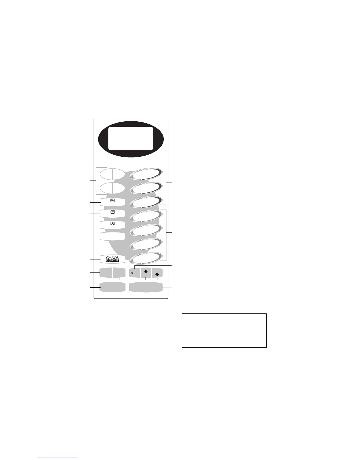
Control Panel
NN-A554/A524/A574*
(1) Display Window
(2) Time Pads
(3) Auto Weight Microwave
Programs
(4) Auto Weight Combination
Programs
(5) Auto Weight Defrost Programs
(Chaos Defrost)
(6) Microwave Power Pad
(7) Grill Pad
(8) Convection Pad
(9) Combination Pad
(10) Delay/Stand Pad:
This can be used to delay a cooking
program for up to 9 hrs 99 mins., or
used to time or for standing (noncooking) time.
(11) Clock Pad
(12) lb/oz Conversion Pad
(13) Weight Selection Pads
(14) Stop/Cancel Pad:
Before Cooking:
one press clears your instructions.
During Cooking:
one press temporarily stops the
cooking program. Another press
cancels all your instructions and the
time of day will appear in the
display.
(15) Start Pad:
Press to start operating the oven. If
during cooking the door is opened
or Stop/Cancel Pad is pressed
once, Start Pad has to be pressed
again to continue cooking.
(1)
(2)
(14)
(11)
(12)
(13)
(15)
(6)
(7)
(8)
(9)
(5)
(10)
(3)
(4)
Beep Sound:
Abeep sounds when a pad is pressed. If
this beep does not sound, the setting is
incorrect. When the oven changes from one
function to another, two beeps sound. After
completion of cooking, five beeps sound.
The design of your control panel may
vary from the panel displayed
(depending on colour), but the words
on the pads will be the same.
3 Control Panel
5
4 Inverter Warnings
The inverter circuit board supplies the magnetron tube with a very high voltage (4000 volts).
Danger
• The inverter circuit board operates at high voltages
and high temperatures.
The Inverter PCB
• Operates at a very high voltage and current.
• Has an aluminium heat sink which becomes very
hot.
• Has capacitors in the circuitry that hold a high voltage charge even when the oven is not operating.
Warning
• Do not touch the high voltage circuit. When replacing the board care must be taken to avoid possible
electric shock.
• Do not touch the aluminium heat sink as it is part of
the high voltage circuit and becomes very hot.
• Do not attempt to repair the inverter PCB, this
can be very dangerous. Replace the high voltage inverter circuit as a complete unit.
• Do not adjust or tamper with the pre-set volume on
the inverter board. It is very dangerous to adjust
this pre-set without proper test equipment.
• Do not operate the microwave oven when the
inverter grounding plate and fixing screw is loose.
It is very dangerous to operate the inverter circuit
board without a proper ground connection.
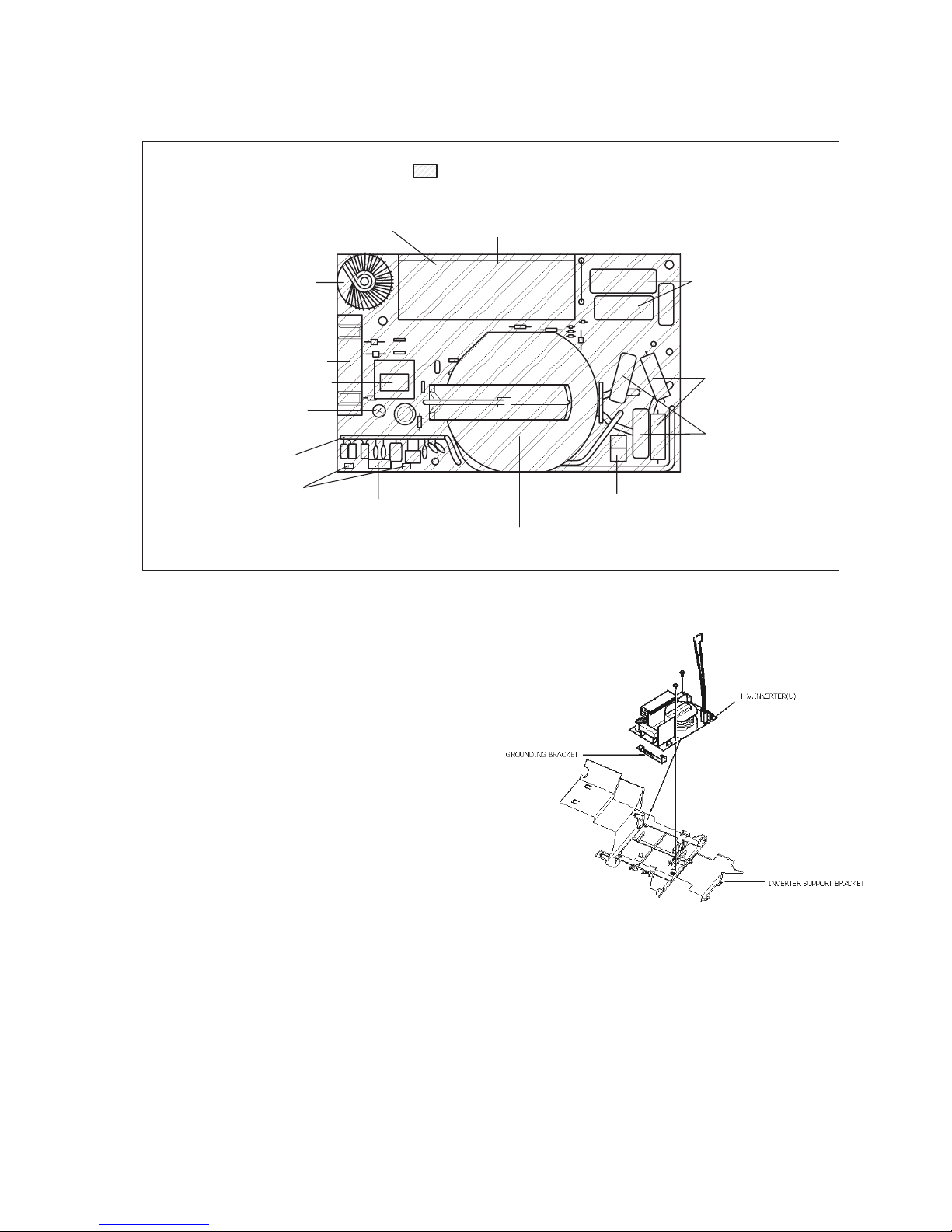
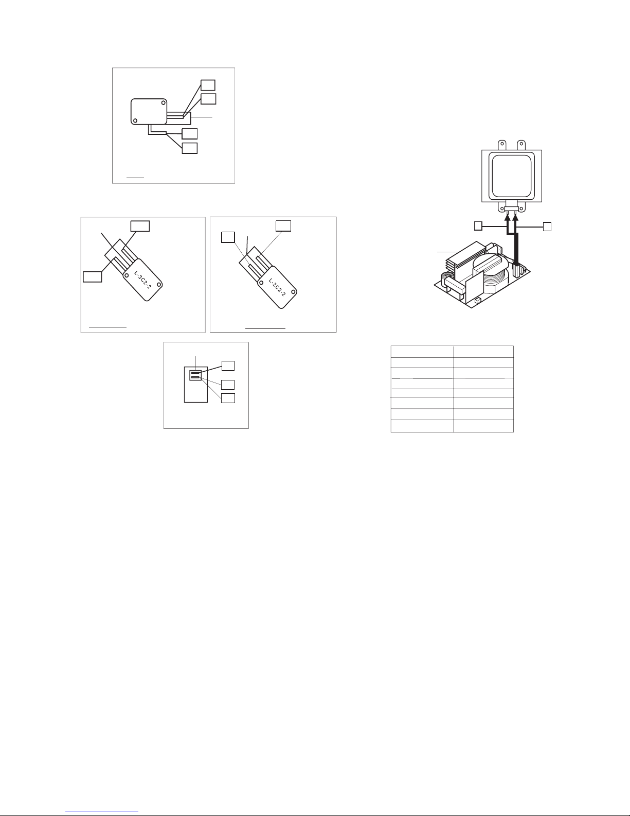
figure 1Assembly of the inverter circuit board
HEAT SINK
RECTIFIER BRIDGE
CHOKE COIL
SAND BAR RESISTOR
CURRENT TRANSFORMER
HIGH VOLTAGE TRANSFORMER
PRESET VOLUME *4
(DO NOT ADJUST)
FILM CAPACITORS
HIGH VOLTAGE
DIODES
HIGH VOLTAGE
CAPACITORS
CN 703
CN 701
CONTROL BOARD
WITH CUSTOM IC
PHOTOCOUPLER
DO NOT TOUCH
HOT/HIGH VOLTAGE *2
HIGH VOLTAGE AREA *1

6
5 Schematic Diagram
7
6 Wiring Diagram
R
NOTE WHEN REPLACIN ANY COMPONENT S RECONNECT THE WIRE HARNESS
ACCORDIN T O THE COLOURS BELOW
COL OURS INDICATED INSIDE BRACKETS () INDICATE THE COLOUR O
THE CONNECTOR HOUSIN
MA NETRON
HI H OL TA E IN ER TER
CAUTION
HEAT SINK
(HOTLIE)
ER Y HI H OL TA E
AND TEMPERATURE
BR
BR
BR
OR
1C2
PRIMARY LATCH SWITCH
TOP
(WH)
WH
WH
SECONDARY LATCH SWITCH
OUTSIDEBOTTOM
BR
(N)
(YE)
YE
SHORT SWITCH
INSIDEBOTTOM
YE
BL
POWER RELAY
(RY1)
(N)
2
1
BL
SYMBOL COLOUR
BL BLUE
BK BLACK
BR BROWN
WH WHITE
YE YELLOW
N NATURAL
R RED
R
 Loading...