

Page 1
Reference
Reference
Page
Outline of “PANATERM®”, Setup Support Software ..............................156
Communications ...................................................................................158
Description on Dividing/Multiplier Ratio ................................................178
Conformance to EC Directives/UL Standards ....................................... 180
Optional Parts .......................................................................................184
Recommended Parts ............................................................................192
Dimensional Outline Drawing ................................................................193
Allowable Load of Output Shaft ............................................................196
Motor Characteristics (S-T Characteristics) ..........................................197
Servo Motor with Gear ..........................................................................198
Dimensional Outline Drawing of Motor with Gear .................................200
Allowable Load of Output Shaft of Servo Motor with Gear ...................202
Characteristics of Servo Motor with Gear (S-T Characteristics) ........... 203
Driver Internal Block Diagram ...............................................................204
Control Block Diagram ..........................................................................205
Specifications (Driver/Motor) .................................................................206
Hit-and-stop Initialization and Load Pressing Control ...........................207
Index .....................................................................................................209
Reference .............................................................................................214
After-sale Service (Repair) ........................................................ Back cover
155
Page 2
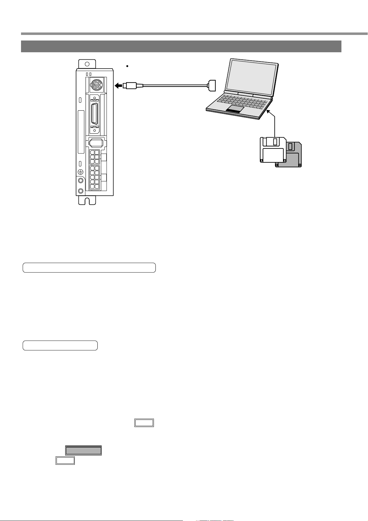
Outline of “PANATERM®”, Setup Support Software
Connection Method
RS-232 Cable
STATUS
ALM CODE
x
6
x
5
x
4
x
3
DV0P1960 (For DOS/V)
Connecting to CN X6
x
1
Please contact us for the latest version of setup disk of
“PANATERM®”, setup support software.
• DV0P4230 (Japanese version)
Windows® 95, Windows® 98, Windows® NT,
Windows® 2000, Windows® Me, Windows® XP
(Each Japanese version)
• DV0P4240 (English version)
Windows® 95, Windows® 98, Windows® NT,
Windows® 2000, Windows® Me, Windows® XP
(Each English version)
Installing PANATERM® on Hard Disk
<Cautions/Remarks>
1. The capacity of hard disk memory should be 15 MB or more. As OS, prepare Windows® 95, Windows® 98,
Windows® NT, Windows® 2000,Windows® Me and Windows® XP (each of them should be a Japanese version).
2. You can start “PANATERM®” only after installing it on the hard disk with the setup disk, by following the steps
described below.
Steps of Procedure
(1) Power on your personal computer and start a corresponding OS (If there is any running application program,
terminate it).
(2) Insert PANATERM® Setup disk 1 into the floppy disk drive.
(3) Start Explorer and select the floppy disk drive.
(For starting of Explorer, see the manual of the corresponding OS.)
(4) Double click on the setup program (Setup.exe) on the floppy disk (Then, PANATERM® setup program will
start.).
(5) To start the setup program, press .
OK
(6) Operate by following the guidance of the setup program.
(Follow the instruction to change the setup disc 1 to disc 2 during the course.)
(7) Click on button, and setup will start.
(8) Click when the message “Setup completed” appears.
Start installation
OK
(9) Close all application programs and then restart Windows®. When it restarts, PANATERM® will be added to
the program menu.
156
Page 3

[Reference]
Reference
Starting PANATERM®
<Cautions/Remarks>
1. Once you have installed “PANATERM®” on the hard disk, you do not have to reinstall it every time you boot up.
2. Before you start, connect the driver with the power supply, motor, and encoder. For the startup procedure, refer
to the manual of the corresponding OS.
Steps of Procedure
(1) Power on your personal computer and start the corresponding OS.
(2) Turn on the driver.
(3) Click on Start button of the corresponding OS of the personal computer.
(For the startup procedure, refer to the manual of the corresponding OS.)
(4) Select PANATERM® in the program .
(5) After opening splash is displayed for 2 seconds, PANATERM® screen will appear.
For any detailed information on operation/functions of “PANATERM®”, refer to the operating instructions of
“PANATERM®”.
* Windows®, Windows® 95, Windows® 98, Windows® NT, Windows® 2000, Windows® Me, Windows® XP are the
trademarks of Microsoft Corporation in the United States.
157
Page 4

Communications
Outline of Communications
With a personal computer or host NC connected with MINAS-E Series through RS232C-compliant serial
communications, you can do the following:
(1) Rewriting parameters
(2) Browsing and clearing status and history of alarm data
(3) Monitoring control status including status, I/O, etc.
(4) Saving and Loading parameters
Advantages
• You can write parameters all at once from the host when starting the machine.
• As you can display operating condition of the machine, serviceability will improve.
Note that the following application programs for a personal computer and cables are available for use. For
information of PANATERM®, refer to the instruction manual of PANATERM®.
Name of Optional Components
PANATERM Japanese version (WIN95/98/Me/NT4.0/2000/XP)
PANATERM English version (WIN95/98/Me/NT4.0/2000/XP)
Connection cable for personal computer (DOS/V)
For the latest version, please contact us.
Model Name
DV0P4230
DV0P4240
DV0P1960
158
Page 5

[Reference]
Reference
Communications Specification
Connection of Communications Line
MINAS-E Series has RS232C communications port. and is capable of communications between the host as follows:
RS232C Communications
In RS232C communications, a host and the driver are connected 1:1 and communicate with each other
according to the RS232C transmission protocol.
RS232C
Host
STATUS
ALM CODE
x
6
X6
x
5
x
4
x
3
x
1
(ID)=1
You can change settings of the module ID with Pr00. In particular, you may set the same module ID unless
there is management problem on the host side.
Interface of Communication Connector Unit
Connection with a Host through RS232C
MINAS-E
X6Host
RTS
CTS
RXD
G
TXD
DTR
DSR
FG
1
2
Equivalent to ADM202E
3
TXD
4
G
5
RXD
6
+5V
+5V
7
8
<Note>
You must leave pins 1, 2, 6, 7 and 8 of X6 unconnected.
159
Page 6
Communications
Communications Method
RS232C
Full-duplex, asynchronous communication method
Communications baud rate
Data
Parity
Start bit
Stop bit
Set RS232C communications baud rate with Pr0C. Any change to these parameters will be valid when you
power on the control power supply. For detailed information, refer to list of parameters related to the following
communications:
List of User Parameters Related to Communications
2400, 4800, 9600bps
8 bit
No
1 bit
1 bit
PrNo.
00
0C
Time for data transmission is calculated with the following expression, for instance, in the case of 9600 [bps]:
When the baud rates of 2400 bps and 4800 [bps] are used, data transmission time will be 4.17 [ms/byte] and
2.08 [ms/byte], respectively. Note, however, actual communication time will be added time necessary for
processing received command, and necessary for switching between a line and transmission/reception control.
Parameter Name
Shaft name
Setting of baud rate for
RS232C communications
(1000/9600) x (1 + 8 + 1) = 1.04 [ms/byte]
Start bit
Range of Setting
1 - 15
0 - 2
Data
Refer to descriptions on parameters on pages 88 and 116.
Set the communications speed of RS232C communications.
0 : 2400[bps] 1 : 4800[bps] 2 : 9600[bps]
A change will be valid when you power on the control power supply.
Stop bit
Functional Description
Handshaking Code
For line control, the following codes are used.
Name
ENQ
EOT
ACK
NAK
Code
05h
04h
06h
15h
Functions
Transmission request
Ready for receiving
Acknowledgement
Negative acknowledgement
ENQ …When the module has a block to transmit, it sends ENQ.
EOT … When the module is ready to receive a block, it sends EOT. The line enters transmission mode when
sending ENQ and receiving EOT. It enters reception mode when receiving ENQ and sending EOT.
ACK … When a received block is judged normal, ACK is returned.
NAK … When a received block is judged as abnormal, NAK is returned. A judgment is made based on
checksum and timeout.
160
Page 7
Reference
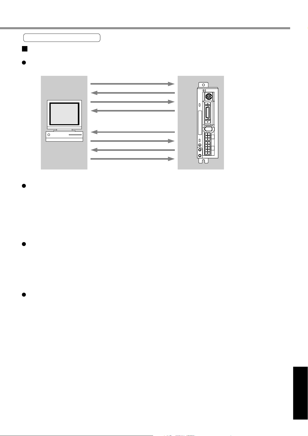
Transmission Sequence
Transmission Protocol
RS232C
Host MINAS-E
[Reference]
(1) ENQ (05h)
(2) EOT (04h)
(3) Data Block
(4) ACK (06h)
(or NAK (15h))
(5) ENQ (05h)
(6) EOT (04h)
(7) Data Block
(8) ACK (06h)
Received
Data
Transmitted
Data
STAT US
ALM CODE
x
6
x
5
x
4
x
3
x
1
(or NAK (15h))
Line Control
Direction of transmission and conflict are solved.
Reception mode …The module enters reception mode after receiving ENQ and returning EOT.
Transmission mode … The module enters transmission mode after sending ENQ and receiving EOT.
When there occurs a conflict between the transmitting module and receiving module:
When subsequent to transmission of ENQ, a slave receives ENQ while waiting for EOT, priority is given to
ENQ sent from a maser, and the slave enters the reception mode.
Transmission Control
Entering transmission mode, a module transmits a command block continuously and then waits for reception
of ACK. When the module receives ACK, transmission is complete. When the number of transferred
command bytes is incorrect, ACK may not be returned. When ACK is not returned within T2 period, or when
NAK or any code other than ACK is received, transmission retry will be executed. The retry will start with
ENQ.
Receiving Control
Entering receiving mode, the module receives transmitted blocks continuously. It obtains the number of
command bytes from the first byte, and receives as many command bytes as that number plus 3. When the
sum of received data is zero, reception is considered successfully ended and ACK is returned. When
abnormal checksum or timeout between characters occurs, NAK is sent.
161
Page 8
Communications
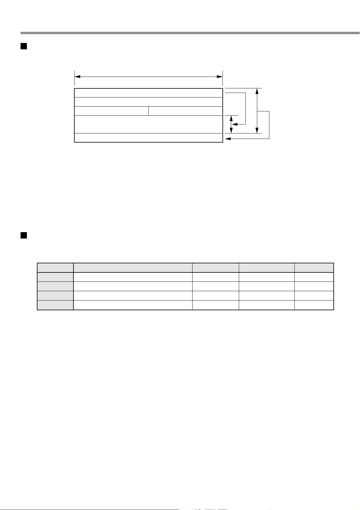
Configuration of Data Block
A data block to be transmitted in physical phase is configured as illustrated below:
1 byte
N
axis
commandmode
Parameter
(N bytes)
check sum
N : This is the number of command bytes (0 - 240),
which indicates the number of parameters needed by a command.
axis : This defines a module ID assigned to parameter No.00 axis name of the driver. (1 - 15)
command : This is the control command (0 - 15).
mode : This is the command execution mode (0 - 15),
which differs depending on a command.
check sum : This is 2’s complement of the total number of bytes, ranging from the first byte to the byte immedi-
ately before the checksum byte.
Protocol Parameter
The following parameters can control transfer of a block. A user can set these parameters to any value with INIT
command to be described later.
Name
T1
Timeout between character transmissions
T2
RTY
M/S
T1 .... • This is allowable time between module identification byte and ENQ/EOT, or time from reception of a
character code by this device to that of a next character code in a transmission/reception data block.
When this specified time is exceeded, timeout error occurs and NAK is returned to the transmitting
module.
T2 .... • This is allowable time after this device transmits ENQ till it receives EOT. When this specified time is
exceeded, it means that the receiving module is not ready to receive data or fails to receive ENQ code
for some reason. In this case, ENQ code will be resent to the receiving module (number of retries).
• This is allowable time after EOT is sent out till a first character is received. When this specified time is
exceeded, NAK is returned and the receiving mode ends.
• This is allowable time after checksum byte is sent out till ACK is received. When this specified time is
exceeded, ENQ code is resent to the receiving module, as in the case of reception of NAK.
Function
Protocol time limit
Retry limit
Master/slave
Initial Value
5 (0.5 second)
10 (10 seconds)
1 (once)
0 (slave)
Range of Settings
1 - 255
1 - 255
1 - 8
0, 1( master)
Unit
0.1 second
1 second
once
RTY ..... This shows the maximum number of retries. When this specified value is exceeded, transmission error
occurs.
M/S ..... This shows switching of a master/slave. When conflict of ENQ transmission occurs, this parameter
determines to which priority is given. (0=slave mode, 1=master mode) Transmission of the module
defined as a master should take precedence.
162
Page 9
[Reference]
Reference
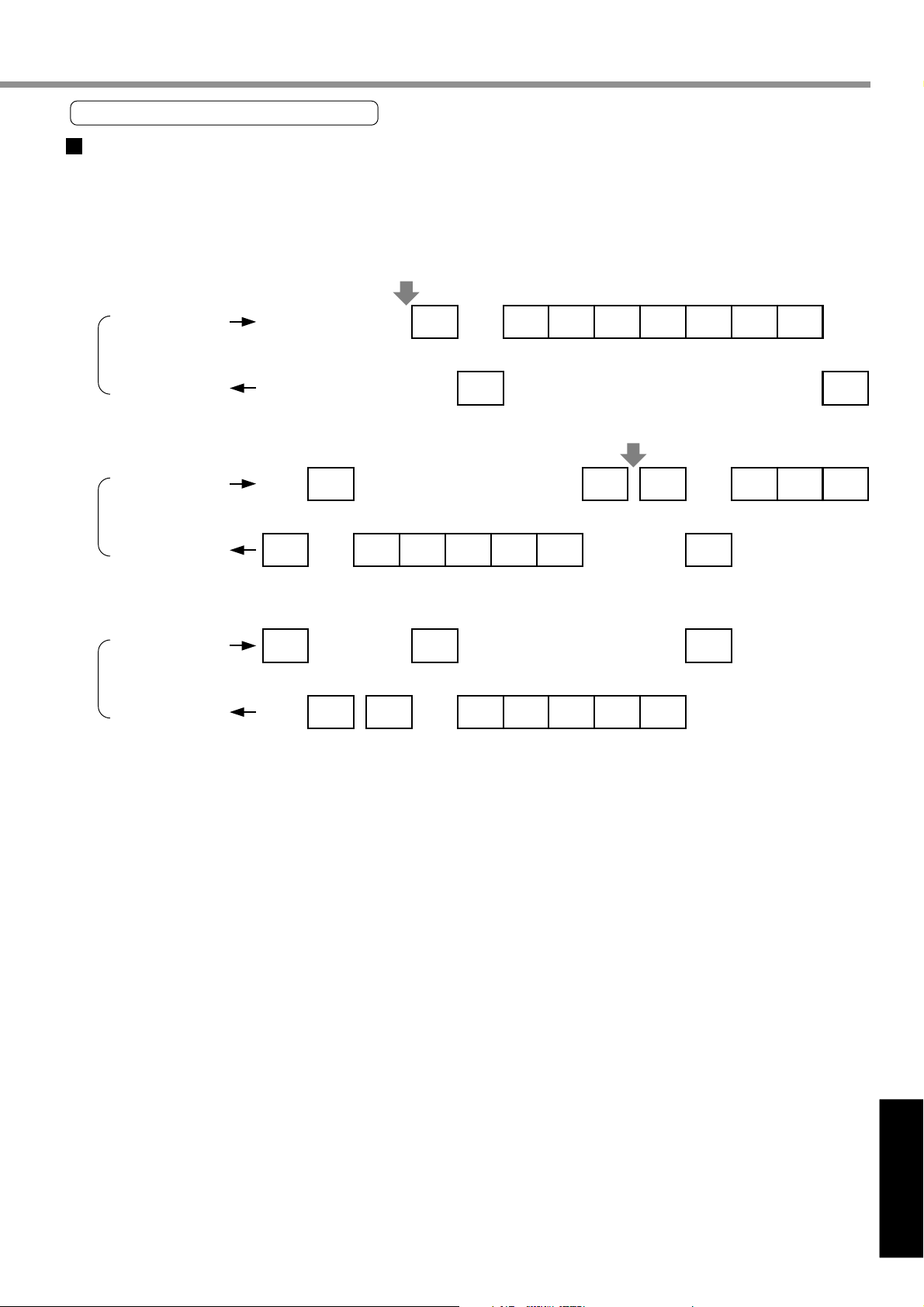
Example of Data Communication
Example of Changing Parameters
The following illustrates time-series communications data flow when a change is made to a parameter.
Communications should be conducted in the sequence of outline, (1) individual writing of parameters and (2) writing
to EEPROM if storage is needed. In this example of hardware connection, the device is directly connected with a
host through RS232C communications with user ID=1. Data is represented in hexadecimals.
(1) Individual Writing of Parameters
Host
MINAS-E(
Host
MINAS-E(
Host
MINAS-E(
1)
1)
1)
05 03 01 18 0B 00 00 D9
(ENQ)
04 06
(EOT) (ACK)
(2) Writing of Parameters to EEPROM
04 06 05 00 01 48
(EOT) (ACK) (ENQ)
05 01 01 18 00 E6 04
(ENQ) (EOT)
B7 04 06
(EOT) (ACK)
06 05 01 01 48 00 B6
(ACK) (ENQ)
(Note) For details of commands, refer to “List of Communications Commands” on Page 166.
163
Page 10
Communications
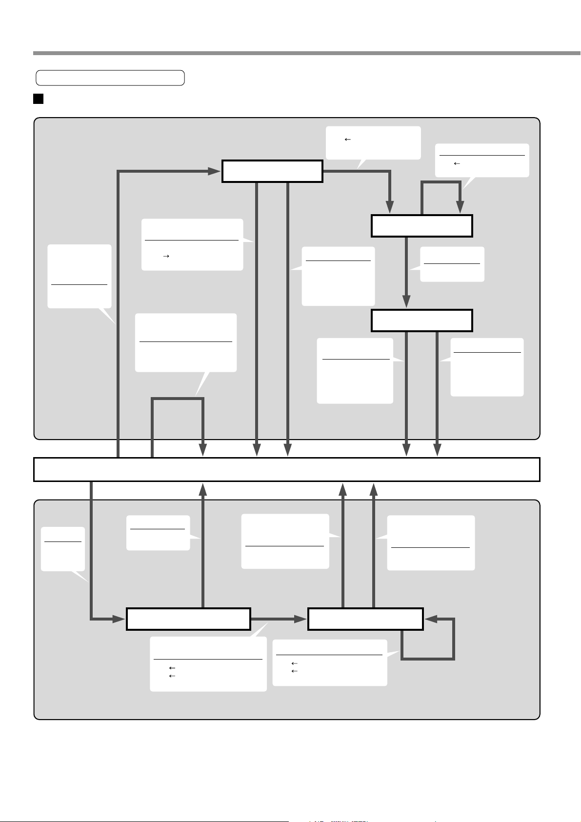
State Transition Diagram
RS232C Communications
There are requests
for transmission
(within the number
of retries).
ENQ transmission
and T2 start.
Transmitting Module
ENQ is received and in slave
mode.
ENQ is returned to receiving
buffer (To reception
processing)
There are requests for
transmission but the number of
retries is exceeded.
The number of retries is to be
reset once. A request for
transmission is cleared.
Waiting for EOT
T2 timeout
The number of retries
is counted once.
T2 stop
Transmission buffer is
cleared.
EOT is received.
Size Number of command
bytes + 3
T2 stop
Transmission of block
Waiting for ACK/NAK
NAK is received or T2
times out.
The number of retries is
counted once.
T2 STOP
Transmission buffer is
cleared.
One character is received.
Size Number of command
bytes - 1
Size becomes zero.
T2 START
ACK is received.
The number of retries
is reset.
T2 stop
The request for
transmission is cleared.
ENQ
EOT is
transmitted.
T2 start
T2 timeout
NAK is transmitted.
T2 stop
Waiting for the number
of command bytes
The number of command bytes is
received.
Size Number of command bytes +3
Sum Number of command bytes
T1 start, T2 stop
Idling
T1 times out or checksum
error occurs when size
becomes 0.
NAK is transmitted.
T1 stop
Remaining blocks
One character is received.
Size Number of command bytes -1
Sum Sum + received characters
T1 start
Receiving module
Receiving
Reception is successful
(checksum is OK when size
becomes 0).
ACK is transmitted.
T1 stop
164
Page 11
Reference
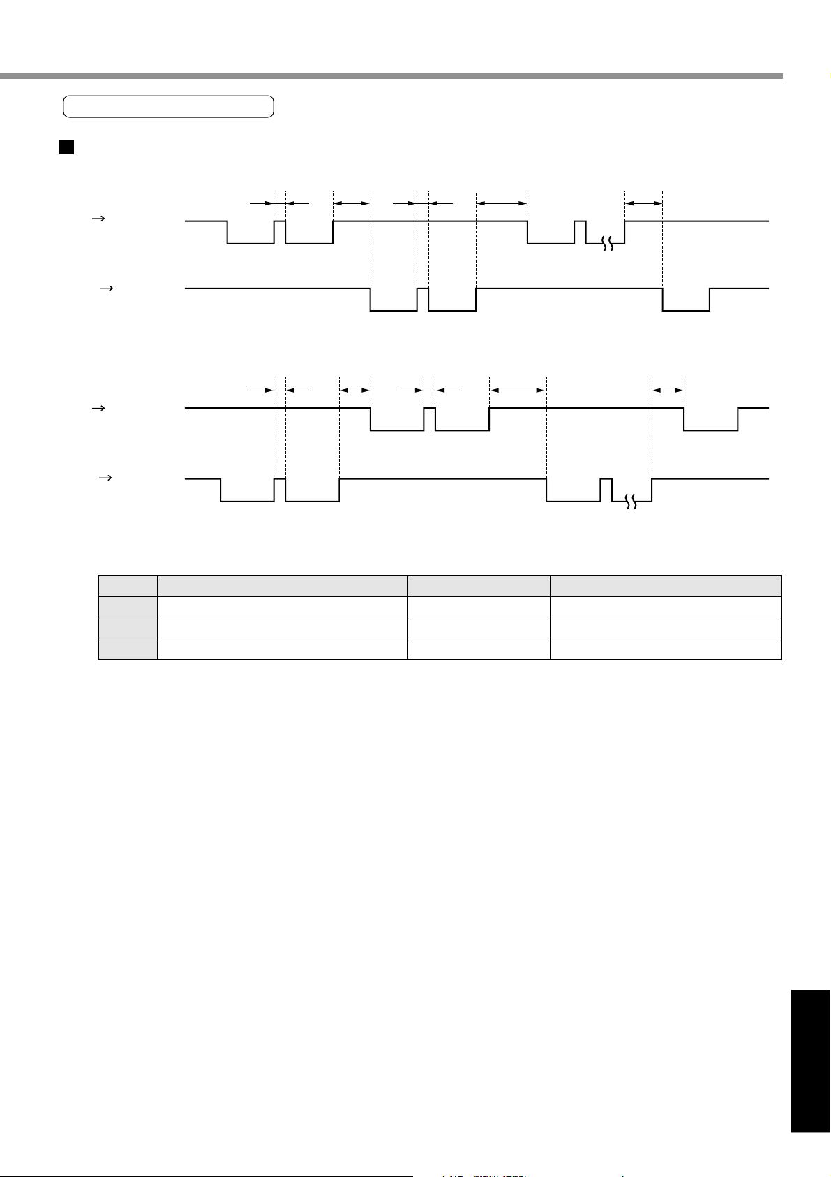
Communications Timing
RS232C Communications
[Reference]
Host Driver
Driver Host
Host Driver
Driver Host
Code
T3
T4
T5
T3 T3T4
Request for transmission
Permission to transmit
T3 T3T5 T4 T5
Request for transmission
Name
Continuous inter-character time
Driver response time
Host response time
T5 T4
Data block
ACK/NAK
Permission to transmit ACK/NAK
Data block
Minimum
Stop bit length
4ms
2ms
Maximum
Protocol parameter T1
Protocol parameter T2
Protocol parameter T2
<Caution>
The time represents a period of time from stop bit rising edge.
165
Page 12
Communications
List of Communications Commands
command
0
1
2
8
9
B
mode
1
5
6
1
0
1
2
4
5
6
7
8
9
A
0
1
4
0
1
2
3
4
0
1
2
Description
NOP
Readout of CPU version
Readout of the driver model name
Readout of the motor model name
INIT
Setting of protocol parameters
POS, STATUS, I/O
Readout of status
Readout of the command pulse counter
Readout of the feedback pulse counter
Readout of current speed
Readout of current torque output
Readout of the current deviation counter
Readout of input signal
Readout of output signal
Readout of current speed/torque/deviation counter
Readout of status/input signal/output signal
PARAMETER
Individual readout of parameters
Individual writing of parameters
Writing of parameters to EEPROM
ALARM
Readout of current alarm data
Individual readout of alarm history
Batch readout of alarm history
Alarm history clear (also on EEPROM)
Alarm clear
PARAMETER
Individual readout of user parameters
Page readout of user parameters
Page writing of user parameters
<Note>
Be sure to use the above commands only. We could not guarantee proper operation of the driver when you
transmit a command not listed above.
Details on Communications Commands
command
0
Error code
bit7
0 : Normal
1 : Error
For version information, Ver. is divided into high order data and low order data and sent back. (The decimal point
returns low-order 4 bits of the high order data as "0".)
A version is expressed by digits of 0 to 9 (Example: Ver.3.13 is composed of high order data 30h and low order data 13h).
This indicates the CPU version.
mode
1
65
Readout of CPU version information
Received data
Command error
Transmitted data
0
axis
01
checksum
43210
Version (high order)
3
axis
01
(low order)
Error code
checksum
166
Page 13
[Reference]
Reference
command
0
Error code
bit7
0 : Normal
1 : Error
mode
5
65
Readout of the driver model name
Command error
Received data
0
axis
05
checksum
43210
The driver model name is 12 characters and transmitted by ASCII code.
ex. "MKDET1505 "
command
0
mode
6
Readout of the motor model name
Received data
0
axis
06
checksum
Transmitted data
0Dh
axis
05
Driver Model Name (high order)
Driver Model Name (low order)
Error code
checksum
Transmitted data
0Dh
axis
06
Motor Model Name (high order)
Error code
bit7
0 : Normal
1 : Error
65
Command error
43210
The motor model name is 12 characters and transmitted by ASCII code.
ex. "MUMA012P1 "
command
1
Error code
bit7
0 : Normal
1 : Error
mode
1
65
Setting of RS232C protocol parameters
Command error
Received data
3
axis
11
T1
T2
RTYM/S
checksum
43
RTY error
T2 error
Motor Model Name (low order)
Error code
checksum
Transmitted data
1
axis
Error code
checksum
2
1
T1 error
11
0
M/S error
Setting of the previous protocol parameters remains valid until execution of this command completes. The updated parameter setting will be
valid from a next command after execution of this command.
M/S=0 indicates "SLAVE" mode, while M/S=1 indicates "MASTER".
The RTY code is 4 bit and M/S is 1 bit.
Unit of T1 and T2 are 0.1 second and 1 second, respectively.
167
Page 14
Communications
command
2
Status
bit7 6 5
Error code
bit7
0 : Normal
1 : Error
mode
0
65
Readout of status
CCW
Torque being output
Command error
The control modes are defined as follows:
0
High speed response positioning control mode
1
Internal velocity control mode
2
High function positioning control
command
2
mode
1
Readout of the command pulse counter
Received data
0
axis
checksum
4
CW
Torque being output
43210
Received data
0
axis
checksum
20
CCW
rotating
21
Transmitted data
3
axis
20
Control mode
Status
Error code
checksum
3
CW
rotating
2
1
Less than DB
permission speed
Transmitted data
5
axis
Counter value L
0
Torque being
limited
21
H
Error code
Error code
bit7
0 : Normal
1 : Error
65
Command error
43210
checksum
A current command position is expressed by absolute coordinates from the start-up time. (Cumulative sum of the number of
command pulses)
The counter value is 32 bits.
For the counter value, "-" indicates CW and "+" indicates CCW.
168
Page 15
[Reference]
Reference
command
2
Error code
bit7
0 : Normal
1 : Error
mode
2
65
Readout of the feedback pulse counter
Command error
Received data
0
axis
checksum
4
Transmitted data
5
axis
22
Counter value L
H
Error code
checksum
3210
22
A current position of the feedback pulse counter is expressed by absolute coordinates from the start-up time.
For the counter value, "-" indicates CW and "+" indicates CCW.
The feedback pulse counter indicates a cumulative sum of pulses of the position detector, which corresponds to a position of
the motor that really moves.
command
2
mode
4
Readout of current speed
Received data
0
axis
checksum
Transmitted data
3
axis
24
Data (current speed) L
H
Error code
checksum
24
Error code
bit7
0 : Normal
1 : Error
6543210
Command error
This command is used to read current speed (unit [r/min]).
An output value is 16 bits.
For the counter value, "-" indicates CW and "+" indicates CCW.
command
2
Error code
bit7
0 : Normal
1 : Error
mode
5
6543210
Readout of current torque output
Received data
0
axis
25
checksum
Command error
This command is used to read current torque output (unit: to be converted as rated torque = 2000).
An output value is 16 bits.
Transmitted data
3
axis
25
Data (torque) L
H
Error code
checksum
169
Page 16
Communications
command
2
Error code
bit7
0 : Normal
1 : Error
mode
6
65
Readout of the current deviation counter
Command error
Received data
0
axis
checksum
4
Transmitted data
5
axis
26
Data (deviation) L
H
Error code
checksum
3210
This command is used to read a current value of the deviation counter. (unit [pulse])
An output value is 32 bits.
"+" indicates that the encoder is in CW direction and "-" indicates that the encoder is in CCW direction relative to the position
command.
command
2
mode
7
Readout of input signal
Received data
0
axis
checksum
Transmitted data
5
axis
27
Data L
26
27
Error code
checksum
Error code
bit7
0 : Normal
1 : Error
Data
bit7
Reserved
bit15
Reserved
bit23
Reserved
bit31
Reserved
6543210
6
Command dividing/
multiplier switching
14
Reserved
22
Reserved
31
Reserved
Command error
5
Zero speed
clamp
13
Internal velocity
command selection 2
21
Reserved
29
Reserved
4
Control mode
switching
12
Internal velocity
command selection 1
20
Reserved
28
Reserved
3
CCW overtravel
inhibited
11
Reserved
19
Reserved
27
Reserved
21
CCW overtravel
inhibited
10
Counter cleared9Gain switching8Reserved
18
Reserved
26
Reserved
Alarm cleared0Servo-ON
Reserved
Reserved
For "CW overtravel inhibited", "CCW overtravel inhibited" and speed zero clamp, "1" indicates the open status.
For other input signals, "0" indicates the open status.
Data H
17
25
16
Reserved
24
Reserved
170
Page 17
[Reference]
Reference
command
2
Warning data
bit7 Overload
bit5 Over-regeneration
bit0 Battery
Error code
bit7
0 : Normal
1 : Error
Data
bit7
Reserved
bit15
Reserved
bit23
Reserved
mode
8
6543210
6
Reserved
14
Reserved
22
Reserved
Readout of output signal
Received data
0
axis
checksum
Command error
5
Torque being
limited
13
Dynamic brake
activated
21
Reserved
Zero speed
detected
Reserved
Reserved
12
20
Transmitted data
7
axis
28
Data L
Data H
Warning data L
H
Error code
checksum
4
3
Electromagnetic
brake released
11
Reserved
19
Reserved
21
Positioning
completed
10
Reserved
18
Reserved
Servo alarm
9
Speed achieved8Reserved
17
Reserved
28
0
Servo ready
16
Reserved
bit31
Reserved
31
Reserved
Reserved
29
28
Reserved
Reserved
The following table shows the relation between each signal and operation.
Signal
Servo ready
Servo alarm
In positioning completed
Electromagnetic brake released
Zero speed detected
Torque being limited
Achieved speed
Dynamic brake activated
command
2
mode
9
Positioning not completed
Electromagnetic brake running
Zero speed not detected
Torque not being limited
Not achieved speed
Dynamic brake released
Readout of current speed/torque/deviation counter
0
not Ready
Normal condition
Received data
0
axis
29
checksum
27
26
Reserved
1
Servo ready
Abnormal condition
Positioning being completed
Electromagnetic brake released
Zero speed detected
Torque being limited
Speed being achieved
Dynamic brake being activated
25
Reserved
Transmitted data
9
axis
Data L
(Speed) H
Data L
(Torque) H
Data L
24
Reserved
29
Error code
bit7
0 : Normal
1 : Error
65
Command error
43210
The speed and torque output values are 16 bits and deviation output value is 32 bits.
The unit and sign of output data are same for command Nos. 24, 25, and 26.
171
(Deviation) H
Error code
checksum
Page 18
Communications
command
2
Error code
bit7
0 : Normal
1 : Error
mode
A
65
Readout of status/input signal/output signal
Command error
Received data
0
axis
checksum
43210
Transmitted data
0Dh
axis
2A
Control mode
Status
Input signal L
Input signal H
Output signal L
Output signal H
Warning data L
Warning data H
Error code
checksum
Meanings of each bit for control mode, status, input signal, output signal, and warning data are same as those of command
No.20 (command=2, mode=0), 27 (mode=7), and 28 (mode=8).
2A
172
Page 19
[Reference]
Reference
command
8
Error code
bit7
0 : Normal
1 : Error
command
8
mode
0
65
mode
1
Individual readout of parameters
Command error
Individual writing of parameters
Parameter value L
H
Received data
1
axis
Parameter No.
checksum
43
Received data
3
axis
Parameter No.
checksum
80
No. error
81
Transmitted data
3
axis
80
Parameter value L
H
Error code
checksum
210
Transmitted data
1
axis
81
Error code
checksum
Error code
bit7
0 : Normal
1 : Error
Data error
6
5
Command error
4
No. error
3
210
This command just changes a parameter temporarily. If you wish to write to EEPROM, execute writing to EEPROM of
parameter (mode=4)
Be sure to set 0 to unused parameters. Otherwise, data error will occur.
command
8
Error code
bit7
0 : Normal
1 : Error
mode
4
6543210
Data error Command error
Writing of parameters to EEPROM
Received data
0
axis
84
checksum
Transmitted data
1
axis
Error code
checksum
Control LV
This command is used to write a set parameters to EEPROM.
Transmission data will be returned after completion of EEPROM writing.
Writing to EEPROM may take approx. 5 seconds max. (if all parameters are changed).
When writing of parameters fails, data error will occur.
When control power supply LV is detected, control LV of error code will be returned, and parameter writing will be disabled.
84
173
Page 20

Communications
command
9
Error code
bit7
0 : Normal
1 : Error
mode
0
6543210
Readout of current alarm data
Received data
Command error
Alarm No. is 0 when no alarm is generated.
(Refer to “Details of Protective Function” on Page 145.)
command
9
mode
1
Individual readout of alarm history
Received data
History No.
0
axis
checksum
1
axis
checksum
Transmitted data
2
axis
90
Alarm No.
Error code
checksum
Transmitted data
3
axis
91
History No.
Alarm No.
Error code
checksum
90
91
Error code
bit7
0 : Normal
1 : Error
6543
Command error
No. error
History No.1 to No.14 indicate the 1st to 14th previous alarm history, respectively.
command
9
Error code
bit7
0 : Normal
1 : Error
mode
2
6543210
Batch readout of alarm history
Received data
0
axis
92
checksum
Command error
The command is used to read 14 previous alarm events.
1st previous
2nd previous
14th previous
210
Transmitted data
0Fh
axis
92
Alarm No.
Alarm No.
~
Alarm No.
Error code
checksum
174
Page 21

[Reference]
Reference
command
9
Error code
bit7
0 : Normal
1 : Error
mode
3
6543210
Data error Command error
Alarm history clear
Received data
checksum
0
axis
Transmitted data
1
axis
93
Error code
checksum
Control LV
The command clears history of alarm data.
When the command fails to clear, data error occurs.
When control power supply LV is detected, control LV of error code will be returned, and parameter writing will be disabled.
command
9
mode
4
Alarm clear
Received data
0
axis
checksum
Transmitted data
1
axis
94
Error code
checksum
93
94
Error code
bit7
0 : Normal
1 : Error
6543210
Command error
This command clears the current alarm (only applicable to alarms that can be cleared).
175
Page 22

Communications
command
B
Attribute
bit7
Unused
parameter
bit151413121110 9 8
Error code
bit7
0 : Normal
1 : Error
mode
0
6
Display inhibited5For privileged
6543210
Individual readout of user parameters
Received data
1
axis
B0
Parameter No.
checksum
4
To be changed at
users
Command error No. error
initialization
System related
Transmitted data
9
axis
B0
Parameter value L
H
MIN value L
H
MAX value L
H
Attribute L
H
Error code
checksum
3
210
Read only
command
Attribute
Unused
parameter
B
bit7
mode
1
6
Display inhibited5For privileged
Page readout of user parameters
users
Received data
1
axis
Page No.
checksum
4
To be changed at
initialization
B1
3
System related
Transmitted data
82h
axis
B1
Page No.
Parameter value L
(No.0) H
MIN value L
(No.0) H
MAX value L
(No.0) H
Attribute L
(No.0) H
Parameter value L
(No.0fh) H
MIN value L
(No.0fh) H
MAX value L
(No.0fh) H
Attribute L
(No.0fh) H
Error code
checksum
210
bit15 14
Error code
bit7
0 : Normal
1 : Error
6543210
Data error
13 12 11 10 9 8
Command error No. error
A page number is designated from 0 to 7, and 16 parameters are read from each page designation.
176
Read only
Page 23

[Reference]
Reference
command
B
Error code
bit7
0 : Normal
1 : Error
mode
2
6543210
Data error Command error No. error
Page writing of user parameters
Received data
21h
axis
B2
Page No.
Parameter L
(No.0 value) H
Parameter value L
(No.1 value) H
~
Parameter value L
(No.0fh value) H
checksum
The command writes 16 parameters at once.
Be sure to set 0 to unused parameters. Otherwise, data error will occur.
Transmitted data
2
axis
B2
Page No.
Error code
checksum
177
Page 24

Description on Dividing/Multiplier Ratio
Relation between Positional Resolution/Moving Speed and Command Dividing Multiplier Ratio
Servo driver
Pulse row position
command
Distance: P1 [P]
Traveling speed: F [PPS]
Command dividing multiplier ratio
Pr4A
D =
Pr46 x 2
Pr4B
Rotation speed: N [r/min]
Servo
motor
Gear
Reduction ratio: R
Machine
Encoder
Number of encoder pulses E [P/r]
10000 = (phase A/B 2500 [P/r] x 4)
Example of driving ball screw using the servo motor
As an example of a machine, we describe a ball screw driving system below:
When lead of a ball screw is L [mm], actual distance of a ball screw M [mm] with respect to the distance command
PI [P] is expressed with formula (1) below:
M = P1 x (D/E) x (1/R) x L................................. (1)
Therefore, position resolution (distance DM per command pulse) is expressed by the following formula (2):
∆∆
∆M = (D/E) x (1/R) x L ....................................... (2)
∆∆
Through transformation of formula (2), a command dividing multiplier ratio D is determined by the formula (3):
∆∆
D = (
∆M x E x R)/L ............................................ (3)
∆∆
In addition, actual traveling speed V [mm/s] of a ball screw with respect to traveling speed command F [PPS] is
expressed by formula (4), and the corresponding motor rotation speed N is determined by formula (5):
V = F x (D/E) x (1/R) x L ................................... (4)
N = F x (D/E) x 60 ............................................. (5)
Through transformation of formula (5), a command dividing multiplier ratio D is determined by the formula (6):
D = (N x E)/(F x 60) ........................................... (6)
<Remarks>
1. Set the positional resolution (∆M) at approx. 1/5 to 1/10 of the positioning accuracy (∆ε), in view of mechanical
errors.
2. Set a value from 1 to 10000 to Pr46 and Pr4B.
3. You can set any value depending on numerator and denominator settings. However, if you specify an extreme
dividing/multiplier ratio, we cannot guarantee proper operation of the motor. We recommend that you set the
dividing/multiplier ratio in the range of 1/50 to 20 times.
4.
n
2
0
2
1
2
2
2
3
2
4
2
5
2
6
2
7
2
8
2
9
2
10
2
11
2
12
2
13
2
14
2
15
2
16
2
17
2
Decimal
1
2
4
8
16
32
64
128
256
512
1024
2048
4096
8192
16384
32768
65536
131072
178
Page 25

[Reference]
Reference
Example
Lead of ball screw L = 10mm
Reduction ratio R=1
Position resolution
1
∆M = 0.005mm
For the encoder of 2500 P/r
(E=10000P/r)
Lead of ball screw L = 20mm
Reduction ratio R=1
Position resolution
2
∆M = 0.005mm
For the encoder of 2500 P/r
(E=10000P/r)
Example
Command dividing
multiplier ratio
D =
0.005 x 10000 x 1
= 5
D =
0.0005 x 10000 x 1
= 0.25
Motor rotation speed (r/min)
10
20
D =
∆M x E x R
L
Determine
parameters Pr46,
Pr4A and Pr4B so
that D=5. Consider
the following:
D =
D<1 is not
appropriate to
determination of
the accuracy.
... Formula (3)
10000 x 2
0
2000
N = F x x 60
D
E
Pr4A
Pr4B
D =
Pr46 x 2
Pr46 = 10000
Pr4A = 0
Pr4B = 2000
D = 1 is a condition
of minimum
resolution.
... Formula (5)
Lead of ball screw L= 20mm
Reduction ratio R=1
Position resolution
∆M = 0.005mm
Line driver pulse input
500 kpps
For the encoder of 2500 P/r
To make motor rotation speed
3000 r/min under the same
condition as above, with lead of
ball screw of L = 20 mm and the
line driver pulse input of 500 kpps.
D =
0.005 x 10000 x 1
20
... Formula (3)
= 25
N = 500000 x x 60
2.5
10000
... Formula (5)
= 7500
Thus, motor specification is not met.
Command dividing
multiplier ratio
D =
N x E
F x 60
... Formula (6)
Determine
parameters Pr46,
Pr4A and Pr4B so
D = = 1
3000 x 10000
500000 x 60
that D=1. Consider
the following:
0
D =
10000 x 2
10000
Then, distance per command pulse (mm) is as follows:
(position resolution)
D
∆M = x x L = x x 20 = 0.002mm
1
E
R
1
10000
1
1
Pr46 x 2
D =
Pr4B
Pr46 = 10000
Pr4A = 0
Pr4B = 10000
Pr4A
179
Page 26

Conformance to EC Directives/UL Standards
EC Directives
The EC Directives apply to all such electronic products as those having specific functions and directly sold to
general consumers in EU countries. These products are required to meet the EU unified standards and to be
furnished with CE Marking.
However, our AC servo meet the EC Directives for Low Voltage Equipment so that the machine or equipment
comprising our AC servo can meet relevant EC Directives.
EMC Directives
Our servo systems can meet EMC Directives and related standards. However, to meet these requirements, the
systems must be limited with respect to configuration and other aspects, e g. the distance between the servo driver
and motor is restricted, and some special wiring conditions must be met. This means that in some cases machines
and equipment comprising our servo systems may not satisfy the requirements for wiring and grounding conditions
specified by the EMC Directives. Therefore, conformance to the EMC Directives (especially the requirements for
emission noise and noise terminal voltage) should be examined based on the final products that include our servo
drivers and servo motors.
Applicable Standards
Subject
Motor
Motor and
driver
IEC: International Electrotechnical Commission
EN: Europaischen Normen
EMC: Electromagnetic Compatibility
Applicable standard
IEC60034-1
EN50178
EN55011 Radio Disturbance Characteristics of Industrial, Scientific
EN61000-6-2 General standards for immunity in industrial environment
IEC61000-4-2 Electrostatic Discharge Immunity Test
IEC61000-4-3 Radio Frequency Electromagnetic Field Immunity Test
IEC61000-4-4 Electric High-Speed Transition Phenomenon - Burst Immunity
IEC61000-4-5 Lightning Surge Immunity Test
IEC61000-4-6 High Frequency Conduction Immunity Test
IEC61000-4-11 Instantaneous Outage - Immunity Test
and Medical (ISM) Radio Frequency Equipment
Te st
Standards referenced
by Low-Voltage
Directives
Standards
referenced by
EMC Directives
180
Page 27

[Reference]
Reference
Peripheral Equipment
Environment
The servo driver should be used under Contamination Level 2 or 1 specified by IEC60664-1 (housing the driver in
an IP54 control box).
Control box
Controller
Power supply for
insulated type
Powe r
Insulating
transformer
Circuit
breaker
Leakage
breaker(RCD)
interface
Noise filter for
signal lines
CN X1
Noise filter
Surge
absorber
Protective earth (PE)
AC ser vo
driver
L1
L2
L3
CN X5
Noise filter for
signal lines
CN
X3
U
V
W
E
CN X4
AC servo
driver
M
RE
Power
+ 10%
Single-phase 100V: Single-phase 100V to 115V 50/60Hz
- 15 %
+ 10%
Single-phase 200V: Single-phase 200V to 240V 50/60Hz
- 15 %
+ 10%
Three-phase 200V: Three-phase 200V to 240V 50/60Hz
- 15 %
(1) Use under the environment of Over-voltage Category II specified by IEC60664-1
In order to realize the environment of overvoltage category II, install in the power supply input unit an insulating
transformer that is compliant with ICE or EN standard (EN 60742).
(2) The power for interface should be marked CE or appropriate EN Standard type (EN60950), 12VDC to 24VDC,
insulated.
+ 10%
- 15 %
+ 10%
- 15 %
+ 10%
- 15 %
Circuit Breaker
Install a circuit breaker between the power supply and noise filter. The circuit breaker should be IEC Standard and
UL listed marked.
181
Page 28

Conformance to EC Directives/UL Standards
Noise Filter
When, one set of noise filters is installed in the power unit with two or more drivers, be sure to consult with the noise
filter manufacturer.
Option Part No.
DV0P4160
Manufacturer’s part No.
3SUP-HU10-ER-6
Manufacturer
Okaya Electric
Industries Co., Ltd.
Surge Absorber
Install the surge absorber on the primary line of the noise filter.
<Note>
When conducting voltage-resistant test on the machine/equipment, remove the surge absorber.
Otherwise the absorber may be damaged.
Circuit diagram
Option Part No.
DV0P1450
Manufacturer’s part No.
R•A•V-781BXZ-4
Manufacturer
Okaya Electric
Industries Co., Ltd.
182
Page 29

[Reference]
Reference
Noise Filter for Signal cables
Provide all the cables (power supply cable, motor cable, encoder cable, interface cable) with the noise filter for
signal cable.
Grounding
Option Part No.
DV0P1460
Weight: 62.8 g
Manufacturer’s part No.
ZCAT3035-1330
Manufacturer
TDK Co., Ltd.
(1) Don’t fail to connect the servo driver protective earth terminal ( ) and the protective earth plate of the control
panel together.
(2) When connecting to the protective earth terminal ( ), avoid co-clamping. Two protective earth terminals are
provided.
Leakage Breaker
Connect Type-B leakage breaker (RCD) to the primary power supply of the servo driver.
Driver and Peripheral Devices Applied Thereto (EC Directives)
For the detail refer to “System Configuration and Wiring“, Page 26.
Install the noise filters in reference to DV0P4160 (page 182).
Conformance to UL Standards
The noise filters conform to UL508C (File No. E164620) to satisfy the following conditions.
(1) The servo driver should be used under Contamination Level 2 or 1 specified by IEC60664-1 (housing the driver
in an IP54 control box).
(2) Install a circuit breaker or fuse between the power supply and noise filter. The circuit breaker or fuse should be
a UL listed mark ( ) type.
The current rating of the circuit breaker or fuse should be per the table in page 26.
183
Page 30

Optional Parts
MINAS-E Series Table of Junction Cable by Model
Figure No.
Motor Type
2-1
MUMA50W - 400W
3-1
4-1
Junction Cable for Encoder
Figure 2-1 MFECA0 * * 0EAM
(16)
(14)
(4) (4)
Manufactured by Tyco Electronics AMP K.K.
Connector 172160-1
Pin 170365-1
Junction Cable
For an encoder (2500 P/r 5 wires)
Incremental
For a motor
For a brake
L
(20)
(ø9.2)
Part No.
MFECAO * * OEAM
MFMCAO * * OAEB
MFMCBO * * OGET
L (m)
3
5
10
20
Manufactured by Molex Incorporated
Connector 55100-0600
Part No.
MFECA0030EAM
MFECA0050EAM
MFECA0100EAM
MFECA0200EAM
Junction Cable for Motors (Robotop® 600V DP)
Figure 3-1 MFMCA0 * * 0AEB
(12.0)
(4) (4)
(10.0)
(50) (50)
Manufactured by Tyco Electronics AMP K.K.
Connector 172159-1
Pin 170362-1
or 170366-1
L
(ø11)
Junction Cable for Brakes (Robotop® 600V DP)
Figure 4-1 MFMCB0 * * 0GET
(10.0)
(40) (50)
(12.0)
(5.6)
Manufactured by Tyco Electronics AMP K.K.
Connector 172157-1
Pin 170362-1
or 170366-1
L
(ø9.8)
Manufactured by Molex Incorporated
Connector 5557-06R-210
Pin 5556PBTL
For pressure
connection terminal M4
Robotop® is a trade mark of
Daiden Co., Ltd.
L (m)
3
5
10
20
L (m)
3
5
10
20
Part No.
MFMCA0030AEB
MFMCA0050AEB
MFMCA0100AEB
MFMCA0200AEB
Part No.
MFMCB0030GET
MFMCB0050GET
MFMCB0100GET
MFMCB0200GET
184
Page 31

Reference
Connector Kits for Power Supply of the Driver
(1) Part No. DV0P2870
(2) Components
[Reference]
Name
Connector (10P)
Connector Pin
Manufacturer’s part No.
5557-10R-210
5556PBTL
Number
1
6
Manufacturer
Molex Incorporated
Remarks
For connector CN X1
(pin 10)
(3) Pin arrangement of connector for CN x 1
10
(NC)
L1
4
5
(NC)
P
(4) Recommended manual pressure bonding tool
(Customers are requested to provide it by
themselves.)
L2
3
B
L3
(NC)
1
2
E
(NC)
Manufacturer’s part No.
57026-5000
57027-5000
Wire rod
UL1007
UL1015
6
7
8
9
<Cautions>
1. The above table shows arrangement of pins viewed from the pin inserting direction of the connector.
Also check pin Nos. carved on the main body of the connector so as to avoid incorrect wiring.
2. For wiring and connection, refer to “System Configuration and Wiring”, Wiring of Main Circuits (Page
27).
3. You should leave a pin labeled with (NC) unconnected.
185
Page 32

Optional Parts
Connector Kits for Connection of Motor and Encoder
Used for: MUMA 50W to 400W Incremental
2500 pulse 5-wire
(1) Part No. DV0P3670
(2) Components
Name
Connector
Connector (6P)
Connector pin
Connector (4P)
Connector pin
Connector (6P)
Connector pin
Manufacturer’s part No.
55100-0600
172160-1
170365-1
172159-1
170366-1
5557-06R-210
5556PBTL
Number
1
1
6
1
4
1
4
Manufacturer
Molex Incorporated
Manufactured by
Tyco Electronics AMP K.K.
Manufactured by
Tyco Electronics AMP K.K.
Molex Incorporated
Remarks
For connector CN X4
(pin 6)
For junction of encoder
cable
(pin 6)
For junction of motor
power line (pin 4)
For connector CN X3
(pin 6)
<Note>
You may use parts of other manufacturer equivalent to the above parts for such components as connector, connec-
tor cover, etc.
(3) Pin arrangement of connector CN X4 plug
2 0V1 +5V
4 0V3 +5V
6 Tx/Rx5 Tx/Rx
(Case FG)
(4) Recommended manual
pressure bonding tool
(A customer is requested to
provide it by himself.)
Name
For junction of encoder cable
For junction of motor power line
For connector CN X3
Manufacturer’s part No.
755330-1
755331-1
57026-5000
57027-5000
Manufacturer
Tyco Electronics AMP K.K.
Molex Incorporated
Wire rod
UL1007
UL1015
<Cautions>
1. The above figure shows the pin arrangement viewed from the soldering side of the connector.
Also check pin Nos. carved on the main body of the connector so as to avoid incorrect wiring.
2. Be sure to connect shield of the shielded wire to be used to the case (FG).
3. For wiring and connection, refer to “System Configuration and Wiring”, Connector CNX4 (Page 29).
186
–
Page 33

Reference
(5) Pin arrangement of connector for junction of encoder cable
[Reference]
1
(NC)
4
+5V
2
TX/RX
5
0V
3
TX/RX
6
FG
(6) Pin arrangement of connector for junction of motor power line
1
U
3
W
2
V
4
E
(7) Pin arrangement of connector for connector CN X3
6
W
3
E
5
(NC)
2
(NC)
4
V
1
U
<Cautions>
1. The above table shows arrangement of pins viewed from the pin inserting direction of the connector.
Also check pin Nos. carved on the main body of the connector so as to avoid incorrect wiring.
2. For wiring and connection, refer to “System Configuration and Wiring”, Wiring of Main Circuits (Page
27).
187
Page 34

Optional Parts
Connector Kit for Connection with Host Controller
(1) Part No. DV0P0770
(2) Components
Name
Connector
Connector Cover
Manufacturer’s part No.
10126-3000PE
10326-52A0-008
Number
1
1
Manufacturer
Sumitomo 3M Ltd
Remarks
For CN X5
(Pin 26)
(3) Pin arrangement of connector X5 (pin 26) (viewed from the soldering side of the connector)
14
GND16OA–18OB–20OZ–22PULS124SIGN126FG
15
OA+17OB+19OZ+21CZ23PULS225SIGN2
1
COM+3A-CLR
2
4
SRV-
CL
ON
7
5
GAIN
CWL9ALM11BRK-
ZEROSPD
6
DIV
INTSPD1INTSPD2
8
CCWL10COIN12WARN
OFF
13
COM–
<Cautions>
1. When wiring, also check pin Nos. carved on the main body of the connector.
2. For codes representative of signal names in the above table or functions of signals, refer to Wiring to
Connector CN X5 (Page 30, 67 and 105).
Interface Cable for Connection with Host Controller
(1) Part No. DV0P0800
(2) Outline dimension
2000
Shell Kit : 10326-52AO-008
Sumitomo 3M Ltd or item equivalent to it
39
12.7
50
2614
37.2
113
Plug : 10126-3000PE
Sumitomo 3M Ltd or item equivalent to it
14
(3) Table of Wiring
Pin No.
1
2
3
4
5
6
7
8
9
Signal Name
COM+
SRV-ON
A-CLR
CL/INTSPD2
GAIN/ZEROSPD
DIV/INTSPD1
CWL
CCWL
ALM
Color of Core Wire
Orange (red 1)
Orange (black 1)
Gray (red 1)
Gray (black 1 )
White (red 1)
White (black 1)
Yellow (red 1)
Yellow (black 1 )
Pink (red 1)
Pin No.
10
11
12
13
14
15
16
17
18
Signal Name
COIN
BRK-OFF
WARN
COM
-
GND
OA+
OA
-
OB+
-
OB
Color of Core Wire
Pink (black 1)
Orange (red 2)
Orange (black 2 )
Gray (red 2)
Gray (black 2)
White (red 2)
White (black 2)
Yellow (red 2)
Yellow (black 2)
Pin No.
19
20
21
22
23
24
25
26
Signal Name
OZ+
OZ
-
CZ
PLUS1
PLUS2
SIGN1
SIGN2
FG
Color of Core Wire
Pink (red 2)
Pink (black 2)
Orange (red 3)
Gray (red 3)
Gray (black 3)
White (red 3)
White (black 3)
Orange (black 3)
<Remarks>
• For example, the color of the wire, Orange (Red 1) means that the lead wire is colored in orange with one red dot
mark.
• The shield of this cable is not connected with the terminal of the connector.
Please use the connector kit for connection with Host Controller when you connect the shield with FG or GND on
the driver side.
188
Page 35

Reference
Communications Cable (Connection with Personal Computer)
(1) Part No. DV0P 1960 (for DOS/V compatible machines)
[Reference]
33
2000
18
Mini DIN8P
D sub connector 9P
MD connector
For pin arrangement of CN X6, see Page 159.
“PANATERM®”, software for communications control
(1) Part No. DV0P4230 (Japanese version) DV0P4240 (English version)
(2) This is supplied in the form of a 3.5 inch floppy disk.
<Cautions>
For details on the operating environment or others, refer to the operating instructions of “PANATERM®”.
For information on latest version, please contact us.
Console
Part No. DV0P3690
MODE
M
S
SET
(62)
MINAS
DIGITAL AC SERVO
SHIFT
(1500)
(15)
(114)
DIN8P mini
MD connector
(24)
Nameplate
M3
depth 5
(15)
Insert screw
Screw down with a tightening
torque of no more than 0.5
N•m.
189
Page 36

Optional Parts
External Regenerative Resistor
Part No.
DV0P2890
DV0P2891
Manufacturer’s
model name
45M03
45M03
Ohmic Value
50 Ω
100 Ω
Specification
Rated Power
10W
10W
Operating Temperature for
Built-in Temperature Fuse
130±2˚C
130±2˚C
Remarks
(Specifications for
the driver voltage)
For single-phase 100V
For single-phase/
three-phase 200V
Manufactured by: IWAKI MUSEN KENKYUSHO CO., LTD.
<Note>
For safety reasons, the external regenerative resistor has a built-in temperature fuse. The built-in
temperature fuse may be disconnected depending on heat dissipation conditions, range of use
temperatures, supply voltage, and load variations.
4.3
57
<Cautions>
The regenerative resistor may be hot.
Take preventive actions against a fire and burn.
Do not mount the regenerative resistor in the vicinity
of an inflammable object or in a place where an
60
52
300
operator may easily touch it by hand.
4.3
65
10
DIN Rail Mounting Unit
(1) Part No. DV0P3811
(2) Outline Dimension
5130.5
140
Female terminal
5556PBTL
(or 5556PBT)
t0.6
<Remarks>
• Two mounting screws (M4 x length 8, pan head
35
20
2-M4 bar ring
(for mounting screws)
(6)
machine screws) are supplied.
• * When extended, the rail stopper is 10mm long.
<Note>
For installation and removal, refer to “Installation” of
Before Use edition on Pages 18 to 19.
Mounting plate
(7)
*
Rail stop
(6)
190
Page 37

Reference
Reactor
[Reference]
Driver
Outline
Frame
Code
MKDE
MLDE
Voltage
Specification
for Power
Source of
Driver
Single-
phase
100V
Single-
phase
200V
Three-
phase
200V
Single-
phase
100V
Single-
phase
200V
Three-
phase
200V
Rated Output
50 - 100W
50 - 100W
50 - 200W
200W
200 - 400W
400W
Reactor Part No.
DV0P227
DV0P220
DV0P228
DV0P220
Figure
1
2
1
2
Figure 1
Figure 2
2-I
C
A
(Mounting dimension)
B
YXZ
NP
SRT
A
(Mounting dimension)
B
4-H
C
D
D
4-H
E
F
(Mounting
dimension)
G
E6-I
F
(Mounting
dimension)
G
Figure
1
2
Part No.
DV0P227
DV0P228
DV0P220
55
65
A
B
80
125
68
83
C
D
90
118
E
90
145
41
70
F
G
55
85
H
ø 7
Width 7 x Length 12
I
M4
M4
Inductance
(mH)
4.02
2
6.81
Rated
Current (A)
5
8
3
• The former Agency of Natural Resources and Energy of Ministry of International Trade and Industry (present
Ministry of Economy, Trade and Industry) established higher harmonics suppression guidelines in September
1994.
(1) Drivers rated 4kW or lower are subject to “Higher Harmonics Suppression Guidelines for Home Electric and
General Purpose Appliances”.
(2) Drivers rated over 4kW are subject to “Higher Harmonics Suppression Guidelines for High Voltage and Special
Customers”.
• The Ministry of Economy, Trade and Industry strongly demands manufacturers to enforce measures to curb
harmonics.
In order to comply with the established regulatory level, connect a power-factor improvement reactor (L) to drivers
of 4 kW or lower. For drivers of over 4kW, determine the level of harmonics according to the guideline and take a
suppression measure, as appropriate.
<Reference>
[Harmonics Suppression Technical Guideline], JEAG 9702-1995, Japan Electric Association
[Harmonic Current Calculation Procedure for General-purpose Inverter at Special Customers], JEM-TR201-1996,
Japan Electrical Manufacturers’ Association
191
Page 38

Recommended Parts
Surge Absorber for Motor Brake
Motor Surge Absorber for Motor Brake
MUMA50W - 400W
• C-5A2 or Z15D151
Ishizuka Electronics Corporation
• The recommended parts are specified items to measure the brake release time.
List of Manufacturers of Peripheral Equipment
Manufacturer/Agent Phone Number Equipment
Matsushita Electric Works, Ltd.
Automation Controls Company
IWAKI MUSEN NKENKYUSHO CO., LTD.
Ishizuka Electronics Corporation
Renesas Technology Corpration.
TDK Corporation
Okaya Electric Industries, Co., Ltd.
Sumitomo 3M Ltd
Tyco Electronics AMP K.K.
Japan Molex Incorporated
Daiden Co., Ltd.
+81-6-6908-1131
http://www.mew.co.jp
+81-44-833-4311
http://www.iwakimusen.co.jp/
+81-3-3621-2703
http://www.semitec.co.jp/
+81-6-6233-9511
http://www.renesas.com/jpn/
+81-3-5201-7229
http://www.tdk.co.jp/
+81-3-3424-8120
http://www.okayatec.co.jp/
+81-3-5716-7290
http://www.mmmco.jp
+81-44-844-8111
http://www.tycoelectronics.com/japan/amp
+81-462-65-2313
http://www.molex.co.jp
+81-3-5805-5880
http://www.dyden.co.jp
As of February 2003
No-fuse breaker
Electromagnetic switch
Surge absorber
Regenerative resistor
Surge absorber for holding brake
Noise filter for signal line
Surge absorber
Noise filter
Connector
Cable
192
Page 39

Reference
Dimensional Outline Drawing
Driver (Frame K) Estimated Mass 0.35 kg
[Reference]
Driver (Frame L) Estimated Mass 0.4 kg
193
Page 40

Dimensional Outline Drawing
Motor
MUMA Series 50W to 400W
LL
LFLRLE
LG
200
Sh6
LBh7
MUMA5A P1
MUMA01 P1
MUMA02 P1
Without a brakeWith a brake
MUMA04 P1
MUMA
MUMA5A P1
MUMA01 P1
MUMA02 P1
MUMA04 P1
Output
50W, 100W
200W, 400W
Model LB
Output
(W)
50
100
200
50
100
200
LL
75.5
92.5
96
124400
107
124
129
157400 14
11
14
11
S
22
8
50
22
8
50
LG
230mm
220mm
LE
2
3
2
3
LF
7
7
(Unit: mm)
LR
24
30
24
30
194
Page 41

Reference
Shaft-end Center Tap TP
[Reference]
Without a brakeWith a brake
MUMA
LA
48
70
48
LC
42
60
42
Specification of Keyed Version
(Dimension)
LZ
3.4
4.5
3.4
LW
14
20
25
14
LK
12.5
18
22.5
12.5
KW
3
4
5
3
KH
Output
50W, 100W
200W
400W
(Unit: mm)
RH
3
6.2
4
8.5
5
3
11
6.2
LH
34
43
34
Mass (kg)
0.40
0.50
0.96
1.5
0.60
0.70
Screw
M3
M4
M5
Rotor Moment of Inertia (x10
0.021
0.032
0.10
0.17
0.026
0.036
Depth
6
8
10
-4
kg·m2)
70
60
4.5
20
25
18
22.5
4
5
4
8.5
5
11
43
1.4
1.9
0.13
0.20
195
Page 42

Dimensional Outline Drawing
Allowable Load of Output Shaft
Radial Load Direction (P)
LR/2
Motor
Series
MUMA
Motor Output
50W, 100W
200W, 400W
LR
P
When Assembled In Operation
Radial Load
147
392
Direction A
Thrust Load Directions (A, B)
A
B
Thrust Load
88.2
147
Direction B
117.6
196
Radial Load
M
Unit: N (1kgf = 9.8N)
Thrust Load
Directions A, B
68.6
245
58.8
98
<Remarks>
If a position of load point varies, calculate allowable radial load P (N) from distance L (mm) of a load point
from mounting flange face, based on the relational expression, so that the result of calculation will be as
follows:
Motor
Series
MUMA
L
P
Motor Output
50W, 100W
200W
400W
Relational Expression
of Load - Load Point
1406
P =
L + 7.5
2940
P =
L – 3
5831
P =
L + 8.8
196
Page 43

Reference
Motor Characteristics (S-T Characteristics)
Note that motor characteristics may vary depending on whether or not there is a brake.
The continuous torque — ambient temperature characteristic shows a value when our standard
flange made of aluminum (having about doubled angle of that of the motor flange) is mounted.
They are characteristics without an oil seal.
[Reference]
Motor
Capacity
50W
100W
Supply Voltage of Driver
AC100V
MUMA5AZP1
Supply Voltage of Driver: At AC100V/200V
Torque
[N¥m]
0.5
Instant
Operation Area
0.25
Continuous
Operation Area
0 1000 2000 3000 4000 5000
Rotation Speed [r/min]
MUMA011P1
Supply Voltage of Driver: AC100V
(A dotted line indicates the case in which the supply voltage drops by 10%.)
* Continuous Torque/Ambient
Torque
0.73
1.0
Instant Operation Area
0.58
0.5
Continuous
Operation Area
0 1000 2000 3000 4000 5000
Rotation Speed [r/min]
Temperature
100
95
50
010203040
Rated Torque Ratio [%]
Ambient Temperature [ßC]
With a Brake
AC200V
* Continuous Torque/Ambient Temperature
100
90
50
0 10203040
Ambient Temperature [ßC]
With a Brake
MUMA012P1
Supply Voltage of Driver: AC200V
Torque
1.0
Instant
Operation Area
0.5
Continuous
Operation Area
0 1000 2000 3000 4000 5000
Rotation Speed [r/min]
* Continuous Torque/Ambient
Temperature
100
95
50
0 10203040
Rated Torque Ratio [%]
Ambient Temperature [ßC]
With a Brake
200W
400W
MUMA021P1
Supply Voltage of Driver: AC200V
(A dotted line indicates the case in which the supply voltage drops by 10%.)
* Continuous Torque/Ambient
Torque
2.0
Instant
Operation Area
1.0
Continuous
Operation Area
0 1000 2000 3000 4000 5000
Rotation Speed [r/min]
Temperature
100
90
50
010203040
Rated Torque Ratio [%]
Ambient Temperature [ßC]
With a Brake
MUMA022P1
Supply Voltage of Driver: AC200V
(A dotted line indicates the case in which the supply voltage drops by 10%.)
* Continuous Torque/Ambient
Torque
2.0
1.0
0
Operation Area
Operation Area
Instant
Continuous
1000 2000 3000
Rotation Speed [r/min]
3300
3800
4000
5000
Temperature
100
90
50
0 10203040
Rated Torque Ratio [%]
Ambient Temperature [ßC]
MUMA042P1
Supply Voltage of Driver: AC200V
(A dotted line indicates the case in which the supply voltage drops by 10%.)
Torque
4.0
Instant
Operation Area
2.0
Continuous
Operation Area
0 1000 2000 3000 4000 5000
Rotation Speed [r/min]
* Continuous Torque/Ambient
Temperature
100
90
50
0 10203040
Rated Torque Ratio [%]
Ambient Temperature [ßC]
With a Brake
With a Brake
* In the case of no oil seal and no brake, the rated torque ratio is 100% at ambient temperature of 40ßC.
197
Page 44

Servo Motor with Gear
Checking Model of Servo Motor with Gear
How to check the model
MUMA011P31N
1~4 5~6 7 8 9 10
Symbol
MUMA
Motor Rated Output
Symbol
01
02
04
Specification of Rotary Encoder
Symbol
P
Method
Incremental
Typ e
Ultra low Inertia
Rated Output
100W
200W
400W
Specification
Number of Pulses
2500P/r
Rated Output
Resolution
10000
Lead Wire
5-wire
Structure of the motor
Specifications of
Position/Speed Detector
Voltage Specification
1 : 100V
2 : 200V
Structure of the motor
Holding Brake
Symbol
No Ye s
3
4
Reduction Ratio
Symbol
Reduction Ratio
1N
2N
4N
1/25
1/5
1/9
198
Page 45

[Reference]
Reference
Check the Combination of Driver and Motor with Gear
This driver was designed for use with the motor designated by us.
Check a name of the series, rated output, voltage specification, and encoder specification of the motor you plan to
use.
Incremental Specification 2500 P/r
Applicable Motors with Gear Applicable Drivers
Power Supply
Single Phase
100V
Single Phase
200V
Three-Phase
200V
Motor Rated Output
100W
200W
100W
200W
400W
100W
200W
400W
Reduction Ratio 1/5 Reduction Ratio 1/9 Reduction Ratio 1/25
MUMA011P * 1N
MUMA021P * 1N
MUMA012P * 1N
MUMA022P * 1N
MUMA042P * 1N
MUMA012P * 1N
MUMA022P * 1N
MUMA042P * 1N
<Note>
You must not use any combination other than those listed below.
MUMA011P * 2N
MUMA021P * 2N
MUMA012P * 2N
MUMA022P * 2N
MUMA042P * 2N
MUMA012P * 2N
MUMA022P * 2N
MUMA042P * 2N
MUMA011P * 4N
MUMA021P * 4N
MUMA012P * 4N
MUMA022P * 4N
MUMA042P * 4N
MUMA012P * 4N
MUMA022P * 4N
MUMA042P * 4N
Driver Model
MKDET1110P
MLDET2110P
MKDET1505P
MLDET2210P
MLDET2510P
MKDET1505P
MKDET1310P
MLDET2310P
MLDET2510P
Driver Frame
Frame K
Frame L
Frame K
Frame L
Frame K
Frame L
<Remarks>
The mark "*" under the model name of the applicable motors refer to the structure of motor.
199
Page 46

Dimensional Outline Drawing of Motor with Gear
Servo Motor with Gear
MUMA01 P31N
MUMA01 P32N
MUMA01 P34N
MUMA02 P31N
MUMA02 P32N
MUMA02 P34N
Without a brakeWith a brake
MUMA042P31N
MUMA042P32N
MUMA042P34N
MUMA01 P41N
MUMA
MUMA01 P42N
MUMA01 P44N
MUMA02 P41N
MUMA02 P42N
MUMA02 P44N
MUMA042P41N
MUMA042P42N
MUMA042P44N
Model
* 220 refers to 200W or higher.
Motor
Output
100W
200W
400W
100W
200W
400W
Reduction
Ratio
1/5
1/9
1/25
1/5
1/9
1/25
1/5
1/9
1/25
1/5
1/9
1/25
1/5
1/9
1/25
1/5
1/9
1/25
L LL LM LT KB1 LF LR LQ LB S LP LH J (LG) LE (G)
192
234,5
200.5
235.5
246
263
288.5
223.5
266
233.5
268.5
279
296
321.5
92.5
96
123.5
124
129
156.5
64
69.5
97
95.5
102.5
130
28.5
26.5
28.5
26.5
38.8
34
61.5
38.8
34
61.5
(unit: mm)
32
20
50
12
45
10
14
67.5
50
30
70
19
62
17
22
92
32
20
50
12
45
10
14
72.5
7
50
30
70
19
62
17
61
40
90
24
75
18
32
20
50
12
45
10
50
30
70
19
62
17
32
20
50
12
45
10
7
50
30
70
19
62
17
61
40
90
24
75
18
22
28
14
22
14
22
28
89.5
100
89.5
104
67.5
92
72.5
89.5
100
89.5
104
25
3
34
5
25
3
34
5
200
Page 47

Reference
Detailed View of Shaft End
[Reference]
LC LA LZ LD
52
78
52
78
Without a brakeWith a brake
98
MUMA
A value of moment of inertia is a motor shaft converted value (of the motor + speed reducer).
52
78
52
78
98
60
90
60
90
115
60
90
60
90
115
M5
M6
M5
M6
M8
M5
M6
M5
M6
M8
Key Dimensions (B × H × LK)
12
20
12
20
12
20
12
20
4 × 4 × 16
6 × 6 × 22
4 × 4 × 16
6
22
× 6 ×
8 × 7 × 30
4
16
× 4 ×
6 × 6 × 22
4 × 4 × 16
6
22
× 6 ×
8 × 7 × 30
(unit: mm)
T LN Mass (kg)
2.5
3.5
2.5
3.5
4
2.5
3.5
2.5
3.5
4
34
43
34
43
1.05
2.20
1.68
2.66
3.2
3.2
4.7
1.25
2.40
2.08
3.06
3.6
5.1
Moment of Inertia (×10-4kg m2)
0.072
0.0663
0.0645
0.218
0.368
0.388
0.533
0.438
0.470
0.076
0.0703
0.0685
0.248
0.398
0.418
0.563
0.468
0.500
201
Page 48

Allowable Load of Output Shaft of Servo Motor with Gear
Radial Load (P) Direction
LR
LR/2
P
Motor Output
100W
200W
400W
Gear Ratio
1/5
1/9
1/25
1/5
1/9
1/25
1/5
1/9
1/25
Thrust Loading (A, B) Direction
A
M
B
Shaft Allowable Load
Radial Load
490
588
1670
490
1180
1670
980
1180
2060
Thrust Load
A, B directions
Unit: N
245
294
833
245
588
833
490
588
1030
Requests Concerning Installation
(1) Do not tap on the shaft when mounting the pulley, sprocket, etc. to the output shaft of the gear head. If you do
tap on it, you may hear abnormal sound.
(2) Give load to the pulley, sprocket, etc., so that force can act on the root of the output shaft, whenever possible.
(3) If you plan to use a rigid coupling, ask us for information on the mounting precision and strength.
(4) The motor has a built-in detector. If you inadvertently give excessive shock to the motor unit when coupling it
with a device, the detector may be broken. Thus, assemble it carefully.
202
Page 49

Reference
Characteristics of Servo Motor with Gear (S-T Characteristics)
[Reference]
Driver
Supply
Voltage
100V
Motor
Output
Reduction
Ratio
100W
200W
Torque
Torque
4.0
3.72
2.0
1.18
8.04
8.0
4.0
2.65
0
0
1/5
Instant
Operation Area
Continuous
Operation Area
Instant
Operation Area
Continuous
Operation Area
600 1000500
Rotation Speed [r/min]
600 1000500
Rotation Speed [r/min]
Torque
Torque
8.0
6.86
4.0
2.25
0
16.0
11.3
8.0
Operation Area
3.72
Operation Area
0
1/9
Instant
Operation Area
Continuous
Operation Area
Instant
Continuous
400 555333
Rotation Speed [r/min]
400 555333
Rotation Speed [r/min]
Torque
Torque
20.0
19.0
10.0
6.27
40.0
33.3
20.0
11.1
Instant
Operation Area
Continuous
Operation Area
0
Instant
Operation Area
Continuous
Operation Area
0
1/25
120 200100
Rotation Speed [r/min]
120 200100
Rotation Speed [r/min]
200V
100W
200W
400W
Torque
Torque
Torque
4.0
3.72
2.0
1.18
8.04
8.0
4.0
2.65
20.0
16.2
10.0
5.39
Operation Area
Continuous
Operation Area
0
Instant
Operation Area
Continuous
Operation Area
0
Operation Area
Continuous
Operation Area
0
Instant
Instant
600 1000500
Rotation Speed [r/min]
600 1000500
Rotation Speed [r/min]
600 1000500
Rotation Speed [r/min]
Torque
Torque
Torque
8.0
6.86
4.0
2.25
0
16.0
11.3
8.0
3.72
0
40.0
28.5
20.0
9.51
0
Instant
Operation Area
Continuous
Operation Area
Instant
Operation Area
Continuous
Operation Area
Instant
Operation Area
Continuous
Operation Area
400 555333
Rotation Speed [r/min]
400 555333
Rotation Speed [r/min]
400 555333
Rotation Speed [r/min]
Torque
Torque
Torque
20.0
19.0
10.0
6.27
40.0
33.3
20.0
11.1
80.0
79.2
40.0
26.4
0
0
0
Instant
Operation Area
Continuous
Operation Area
Instant
Operation Area
Continuous
Operation Area
Instant
Operation Area
Continuous
Operation Area
120 200100
Rotation Speed [r/min]
120 200100
Rotation Speed [r/min]
120 200100
Rotation Speed [r/min]
203
Page 50

Driver Internal Block Diagram
U
CN X3
M
V
W
RE
E
CN X4
A/D
PWM
Speed
+
+
Circuit
Current
Control
Limit
Torque
Error
Driver
-
of Speed
Detection
Processing of
Encoder Signal
Dividing
Process
Gate Drive
Protective Circuit
Detection of Abnormality
+
EEPROM
+3.3V
+5V
Gate Drive Power Supply
RE Power Supply
DC/DC
L 2
N
L 3
P
Internal Block Diagram of MINAS-E Driver
L 1
CN X1
P
Sequence Control
B
External Regenerative
Resistor
Parameter Control
Display
Control
CN X6
Alarm Signal
CN X5
Speed
Position
Driver
Position Error
Counter
Deviation
-
+
Dividing/
Multiplier
Pulse Row
Command
Internal Command Speed
Control Input
Control Output
Pulse Output
204
Page 51

Reference
Control Block Diagram
Selection of Control Mode
Pr02
Torque
Command
Torque Command
Waveform Graphic
PANATERM
Pr5E
Pr71
Torque Limit
1st
2nd
Encoder Signal
(Phases A/B)
[Reference]
Encoder Signal (Phase Z)
Select with
Control Mode
: Internal Velocity
: Position Control Mode
: Servo Gain/Filter Time Constant Related Block
S
P
Pr11
Driver
Speed Error
1st Speed
1st
Torque
Command Filter
Notch Filter
Pr19
Pr12
ntegration
2nd
+
Pr02
P
+
+
1st
2nd
Error
Pr10
Driver
Position
Position
Graphic
Position
Deviation
Waveform
Filter
Pr16
Feed Forward
Control Block Diagram
Pr15
Forward
Velocity Feed
Counter
Deviation
+
Filter
Frequency Pr2B
Setting of Filter Pr2C
Vibration Damping
Speed
Graphic
Waveform
Command
Filter
Pr4C
Smoothing
Pr14
Pr1C
1st
2nd
Pr1E
Pr1D
Width
Frequency
Pr20
Pr1A
Speed
2nd
ntegration
Inertia Ratio
-
Position
PANATERM
Filter
Speed Detection
S
Pr18
Position Control Mode
-
PANATERM
External Switching
Position Control Mode
Speed Setting Internal/
4 times
PANATERM
Pr13
1st
2nd Pr1B
Actual Speed
Waveform Graphic
PANATERM
Command Speed
Waveform Graphic
Velocity Control Mode
Pr59
Pr58
Acceleration
Deceleration
Speed
Detection
PANATERM Monitor
Between Acceleration and Deceleration
Pr54
Pr55
Internal 2nd
Speed
Internal 3rd
Speed
Pr56
Internal 4th
Speed
Pr53
Internal 1st
Speed
Multiplier
Feedback Pulse
Pr44
Inversion
Dividing
Pr45
Pr4A
Scale
Numerator
2
Multiplier
Denominator
Pr46
Command Dividing/
Numerator
FIR Filter
Monitor
Total of
Command
PANATERM
Setting
Input Mode
PULS
Pulse Row
Command
Pr4E
ulses
Pr42
SIGN
Pr4B
205
Feedback Pulse (OA•OB)
Feedback Pulse (OZ•CZ)
Page 52

Specifications
Single-phase 100V
Power
Single-phase 200V
Supply
Three-phase 200V
Allowable frequency variations
Control method
Detector
Specification of applicable rotary encoder
Regeneration
Dynamic brake
Built-in
functions
Auto gain tuning
Electronic gear
(Dividing/multiplier of a command pulse)
Dividing of feedback pulse
Capable of storing 14 alarms
Protective
Function
Driver
Monitor
Setting
including a current alarm code
No.
Note, however, that alarm
marked with * cannot be stored.
Panel Display
Communications
Maximum Input Pulse Frequency
Position
Control
Velocity
Form
Type
Internal command speed
Control
Acceleration time setting
Rotary
Encoder
Rotary encoder
feedback signal
Phases A B
Phases
Control Input
Structure
Mass
Ambient Conditions
Rated Rotation Speed
100V
Maximum Rotation Speed
200V
Holding Brake
Rotary Encoder
Motor
Structure (dust-proof/drip-proof protection)
Mass
Ambient Conditions
Single-phase AC100V
Single-phase AC200V
Three-phase AC200V
+10%
—15%
+10%
—15%
+10%
—15%
- 115V
- 240V
- 240V
+10%
—15%
+10%
—15%
+10%
—15%
50/60Hz
50/60Hz
50/60Hz
Within –5%
IGBT transistor PWM control (Sine wave driving)
Incremental encoder 5-wire 2500 P/r
Externally installed regenerative resistor
At power-off, Servo-OFF, activation of protective function, and activation
of limit switches
Normal, real time
A value resulting from the calculation of
1 - 10000
1 - 10000
0 - 17
2
Two-phase pulse of 5 to 2500 P/r output at any number of pulse
Undervoltage*, overvoltage, overcurrent, overload,
regenerative overload, encoder error, position over-deviation,
over-speed, command pulse dividing error, position deviation
overflow, EEPROM data error* (abnormal parameter,
abnormal check code), overtravel input error*, etc.
Status LED (STATUS), alarm code LED (ALM CODE)
RS232C
Line driver 500 kpps, open collector 200 kpps
Line driver, open collector
90ß phase difference two-phase pulse, CW/CCW pulse, pulse row + sign
Four-speed setup (Capable of setting CW/CCW, up to
20000r/min. However, use it within the use range of the motor.)
0 to 10 s/1000r/min, possible to individually set acceleration/
deceleration.
Line driver output
Z
Line driver output, Open collector output
Refer to Section "System Configuration and Wiring".
Base mount type, open (IPOO)
Refer to Section "Dimensional Outline Drawing of Driver".
Refer to Section "Installation".
3000r/min
50W - 200W: 5000r/min
50W - 400W: 5000r/min
Refer to Section "Holding Brake Built in the Servo Motor" for DC24V.
Incremental encoder 5-wire 2500 P/r
Equivalent to IP65 (excluding connector unit, shaft-through part)
Refer to Section "Dimensional Outline Drawing".
Refer to Section "Installation".
206
Page 53

Reference
Hit-and-stop Initialization and Load Pressing Control
[Reference]
Hit-and-stop Initialization
When you find it difficult to install a sensor as the surroundings are not good, Hit-and-stop
Initialization can be used.
(2)
(1) When you set a point where the motor hits,
as the origin:
When you stop the motor using phase Z
with the hit point as a starting point, and
make it an origin
1st
Pin 5
(ZEROSPD/TC)
WARN
(Torque being limited)
Torque
Hitting
Counter
clear
command
Motor
rotation
speed
(1) (2) (1)
2nd Torque Limit 2nd Torque Limit
ON
ON
50%
ON
Pin 5
(ZEROSPD/TC)
WARN
(Torque being limited)
Torque
Counter
clear
command
Motor
rotation
speed
Phase Z
1st
Hitting
(2)
ON
ON
ON
(3)
(1)
(2)
Initial Point
Parameter No.
70
71
72
73
06
09
<Note>
Set pin 5 "H (OFF)" after hit-and-stop initialization completes.
1st over-speed level set-up
2nd torque limit set-up
2nd position over-deviation set-up
2nd over-speed level set-up
ZEROSPD/TC input selection
Warning output selection
Name
Example of Settings
6000
50 (Set it 100% or less)
1875
(Same as No.1)
6000
2
Speed zero clamp disabled.
Torque limit switching input enabled.
0 (Torque being limited)
(1)
(2)
Initial Point (3)
207
Page 54

Hit-and-stop Initialization and Load Pressing Control
Load Pressing Control
Example of Application
Press-fit Machine
(1) (2) (3) (4) (5)
Pin 5 (ZEROSPD/TLC
: Torque limit switching input)
On
PrNo.
06
09
5E
70
71
72
73
Name
ZEROSPD/TC input
selection
Warning output selection
Torque limit set-up
1st over-speed level
set-up
2nd torque limit set-up
2nd over-position
deviation set-up
2nd over-speed level
set-up
Example of
Settings
2
0
200
3000
50
10000
3000
Pin 11 (WARN
: Under Torque limit output)
The value of second torque limit
Torque
Command
Motor Rotation Speed
(+)
(–)
(+)
(–)
(+)
(–)
On
B
A
Search Speed
(Low Speed)
C = A + B
Distance for which the motor has not
moved is held in the deviation counter
(1) (2) (3) (4) (5)
208
Page 55

Reference
Index
[Reference]
A
Items Terms page
Adjustment
Real time Auto Gain Tuning (Position Control Mode)
Real time Auto Gain Tuning (Velocity Control Mode)
Gain Adjustment
Normal Auto Gain Tuning
Cancellation of the Automatic Gain Tuning
Manual Gain Tuning
To Reduce Mechanical Resonance
Adaptive Filter
Gain Switching Function
Anti-Vibration Control
86
114
128
132
135
136
140
131
138
142
Alarm Code
Driver
Protective Functions
Model Designation
Name plate
Combination of Driver and Motor
Check the Combination of Driver and Motor with Gear
Parts Description
Dimensional Outline Drawing
Specifications (Driver/Motor)
144
14
14
15
199
16
193
206
B
Items Terms page
Block Diagrams
Brake
Control Block Diagram in Position Control Mode
Control Block Diagram in Velocity Control Mode
Driver Internal Block Diagram
Holding Brake
Dynamic Brake
60
104
204
35
36
C
Items Terms page
Communications
Protocol
Control Mode
Outline of Communications
Communications Specification
Interface of Communication Connector Unit
Communications Method
Transmission Sequence
Configuration of Data Block
Protocol Parameter
State Transition Diagram
Communications Timing
List of communications Commands
Connections and Setting in Position Control Mode
Connections and Setting in Internal Velocity Control Mode
209
158
159
159
160
161
162
162
164
165
166
65
103
Page 56

Index
D
Items Terms page
Display (Monitor)
Monitoring Mode
EEPROM Writing Mode
Parameter Setting Mode
Normal Auto Gain Tuning Mode
Alarm Clear
51
50
57
58
59
Dividing-Multiplier
Description on Dividing/Multiplier Ratio
178
E
Items Terms page
Encoder Incremental specification 2500P/r 15
H
Items Terms page
Hit-and-stop
Homing Operation
Hit-and-stop Initialization
Homing Operation (Precautions)
207
38
I
Items Terms page
International Standards EMC Directives
EC Directives
Peripheral Equipment
Applicable Standards
List of Available Components
180
180
181
180
183
L
Items Terms page
Load Pressing Load Pressing Control 208
M
Items Terms page
Motor Model Designation
Name Plate
Check the Combination of Driver and Motor
Parts Description
Allowable Load of Output Shaft
Dimensional Outline Drawing
Motor Characteristics (S-T Characteristics)
15
15
15
16
196
194
197
210
Page 57

[Reference]
Reference
O
Items Terms page
Option
Noise Filter
Surge Absorber
Noise Filter for Signal cables
Table of Junction Cable by Model
Junction Cable for Encoder
Junction Cable for Motors
Junction Cable for Brakes
Communications Cable (Connection with Personal computer)
[PANATERM®], Software for Communications Control
Connector Kits for Connection of Motor and Encoder
Connector Kit for Connection with Host Controller
Interface Cable for Connection with Host Controller
External Regenerative Resistor
Reactor
Console
DIN Rail Mounting Unit
182
182
183
184
184
184
184
189
189
186
188
188
190
191
189
190
Overload Time Limit
Characteristics
Overload Protection
146
P
Items Terms page
PANATERM®
Parameters
Peripheral Equipment
PANATERM®
Parameter Groups and Listing
Position Control Mode
Velocity Control Mode
List of Driver and Compatible Peripheral Equipment
Magnetic Contactor
Cable Diameter
Circuit Breaker
Surge Absorber
Noise Filter
Noise Filter for Signal Cables
Grounding
Leakage Breaker
List of Manufacturers of Peripheral Equipment
39
41
88
116
26
26
26
26
182
182
183
183
183
192
211
Page 58

Index
R
Items Terms page
Recommended Parts Surge Absorber for Motor Brake 192
S
Items Terms page
Safety Precautions
Safety Precautions
Maintenance and Inspection
12
8
Servo Motor with Gear
Model Designation
Checking the Combination of the driver and the motor with gear
Dimensional Outline Drawing of Motor with Gear
Allowable load of Output Shaft of Servo Motor with Gear
Characteristics of Servo Motor with Gear (S-T Characteristics)
14
199
200
202
203
T
Items Terms page
Test Run
Timing Chart
Troubles
Inspection prior to Test Run
Test Run Procedure
Test Run in Position Control Mode
Test Run in Internal Velocity Control Mode
After Power-ON
After an Alarm event
After an Alarm is Cleared
Servo-ON/OFF Operation When the Motor is Stopped
Servo-ON/OFF Operation When the Motor is Rotating
Troubleshooting
60
61
82
110
32
33
33
34
34
150
U
Items Terms page
Using Console Structure of Operation Panel and Display
How to Operate
212
47
48
Page 59

[Reference]
Reference
W
Items Terms page
Wiring Installation of Driver
Installation of Motor
General Wiring Diagram
Wiring of Main Circuits
Wiring Diagrams
Connection with Encoder
Connection with Personal Computer/Console
Connection with Host Controller
Wiring in Position Control Mode
Wiring in Velocity Control Mode
18
20
24
27
28
29
31
30
67
105
213
Page 60

Reference
Motor Company, Matsushita Electric Industrial Co., Ltd. Marketing Group
Tokyo: Kyobashi MID Bldg, 2-13-10 Kyobashi, Chuo-ku, Tokyo 104-0031 TEL (03) 3538-2961
FAX (03) 3538-2964
Osaka: 1-1, Morofuku 7-chome, Daito, Osaka 574-0044 TEL (072) 870-3065
FAX (072) 870-3151
214
Page 61

Reference
MEMO
[Reference]
215
Page 62

After-Sale Service (Repair)
Repair
• Ask the seller where the product was purchased for details of repair work.
When the product is installed in a machine or device, consult first the manufacture of the machine or device.
Cautions for Proper Use
• This product is intended to be used with a general industrial product, but not designed or manufactured to be
used in a machine or system that may cause personal death when it is failed.
• Install a safety equipments or apparatus in your application, when a serious accident or loss of property is
expected due to the failure of this product.
• Consult us if the application of this product is under such special conditions and environments as nuclear
energy control, aerospace, transportation, medical equipment, various safety equipments or equipments which
require a lesser air contamination.
• We have been making the best effort to ensure the highest quality of the products, however, application of
exceptionally larger external noise disturbance and static electricity, or failure in input power, wiring and components may result in unexpected action. It is highly recommended that you make a fail-safe design and
secure the safety in the operative range.
• If the motor shaft is not electrically grounded, it may cause an electrolytic corrosion to the bearing, depending
on the condition of the machine and its mounting environment, and may result in the bearing noise. Checking
and verification by customer is required.
• Failure of this product depending on its content, may generate smoke of about one cigarette. Take this into
consideration when the application of the machine is clean room related.
• Please be careful when using in an environment with high concentrations of sulphur or sulphuric gases, as
sulphuration can lead to disconnection from the chip resistor or a poor contact connection.
• Take care to avoid inputting a supply voltage which significantly exceeds the rated range to the power supply
of this product. Failure to heed this caution may result in damage to the internal parts, causing smoking and/or
a fire and other trouble.
Electronic data of this manual
Electronic data of this manual can be downloaded at the following web site.
• Web Site of Motor Company, Matsushita Electric Industrial Co., Ltd.
<http://panasonic.co.jp/motor/>
Memorandum
Date of
purchase
(Fill in the blanks for convenience in case of inquiry or repair)
Date:
Model No.
(Driver)
(Motor)
Place of
purchase
TEL:
Motor Company
Matsushita Electric Industrial Co., Ltd.
7-1-1, Morofuku, Daito, Osaka 574-0044, Japan
TEL: +81 -72-871 -1212
IMC80A
S0303-3066
 Loading...