

Page 1

Instruction Manual
Ultra High-Speed Laser Displacement Sensor (CCD Style)
HL-C1C series
Intelligent Monitor
HL-C1AiM
KA106AiM-E-001
Page 2

Contents
Chapter 1 Before Use
1-1 Introduction ………………………………………………... 1-1
1-2 Cautions for Installation ………………………………… 1-1
1-3 Operating Environment ………………………………….. 1-1
1-4 Installation / How to use ……………………………….. 1-2
1-5 Note ………………………………………………………... 1-3
Chapter 2 Easy Operation Procedure ………………………….. 2-1
Chapter 3 Function Items
3-1 Menu Bar …………………………………………………. 3-1
3-1-1 File Menu ............................................................... 3-1
3-1-2 Window Menu ……………………………………….. 3-2
3-1-3 System Menu ………………………………………... 3-4
3-1-4 Help Menu …………………………………………… 3-7
3-2 Main Display ……………………………………………… 3-9
3-3 Measurement Conditions Setting ……………………… 3-13
3-4 Display Waveform of Measurement Values …………. 3-15
3-5 Display Waveform of Light Received Data …………. 3-19
3-5-1 “Head 1 Setting” Tab Sheet ……………………… 3-23
3-5-2 “Head 2 Setting” Tab Sheet ……………………… 3-24
3-5-3 “Chart Setting” Tab Sheet ………………………… 3-25
3-5-4 “The Others” Tab Sheet …………………………… 3-26
3-6 Emitted Light Amount Search …………………………. 3-28
3-7 Display Data Buffering ………………………………….. 3-29
3-7-1 Data Buffering Procedure ..................................… 3-29
3-7-2 Display Data Buffering ……………………………... 3-29
3-8 Initialize ……………………………………………………. 3-35
Chapter 4 Error Message
4-1 Dialog Display …………………………………………….... 4-1
4-2 Error Message …………………………………………....... 4-1
4-2-1 COM port error ..................................................…… 4-1
4-2-2 Transmission / reception time-out …………………... 4-1
4-2-3 Reception error ........................................................ 4-2
4-2-4 Occurrence of reception time-out …………………… 4-2
4-2-5 Controller version is wrong ………………………….. 4-2
4-2-6 Product code of controller does not match ………… 4-3
4-2-7 Can not open file ……………………………………… 4-3
4-2-8 Can not create file ……………………………………. 4-3
Page 3

Chapter 1 Before Use
Page 4

1-1 Introduction
The HL-C1AiM (Advanced Intelligent Monitor) is function setting software designed for the
controller of the laser type displacement sensor "HL-C1" series.
Connection to the controller using the exclusive cable enables use of the following
functions.
* Setting of various measurement conditions and indication of measurement value
* Monitoring of measurement data
* Monitoring of light received data
* Monitoring of buffering data
1-2 Cautions for Installation
* Prior to installing the software, be sure to read the “Agreement of software use” described
on the rear side of package jacket.
* On installation of the software the user accepts to the agreement described on the rear
side. If the conditions outlined in the agreement cannot be accepted the unused software
should be returned to the origin of purchase.
1-3 Operating Environment
OS : Microsoft Windows 98/98SE/ME/2000/XP
CPU : Celeron 400MHz or higher
Memory : 64MB or higher
Hard Disc : 15MB of available memory is required
CD-ROM Drive : Required for installation
Display : 1024 x 768 resolution 256 color
Serial Port : RS-232C 115.2kbps
* This program cannot be used with any previous version of the current controller version
2.12.
1-1
Page 5

1-4 Installation / How to use
(1) Insert HL-C1AiM into CD-ROM drive.
(2) Execute the setup.exe in HL-C1AiM.
(3) Follow the instructions for setup.
< Important >
In case of installing/uninstalling HL-C1AiM in/from Windows 2000/XP, the administrator
authority is required.
(4) Connect HL-C1C to PC by using the COM port connection cable provided.
(5) Power the HL-C1C on.
(6) Execute ‘Start’ -> ‘Program’ -> ‘SUNX’ -> ‘HL-C1AiM’.
Cautions on handling CD-ROM
1.Do not leave this CD-ROM in direct sunlight or in warm or humid location.
2.Avoid getting fingerprints, dirt, scratching etc. on both sides.
3.Take care that CD-ROM is not brought into contact with LP cleaning liquids, solvents,
water or oil etc.
4.Never use cracked, distorted, or repaired disc.
5.Do not write anything using a pencil, ball-point pen or an oil-based pen etc. on the
surface of the CD-ROM.
Furthermore, do not attach labels etc.
6.Store this CD-ROM in the original CD case.
7.Do not put/drop anything heavy on the original case. The case may be damaged.
8.Never play this CD-ROM on an audio CD player. The loud noise may damage your
ears or break the speakers.
1-2
Page 6

1-5 Note
* The functions that cannot be used with version 2.xx will be inactive, and setting will not be
possible.
* Of “Standard” or “WL” is selected as a product code, the special GS type controller
function becomes inactive and it cannot be selected.
* The functions which cannot be used with the product code “WL” goes into non-active state
and the setting becomes impossible.
*Please set CSV with a CSV setting screen when use the CSV file output with AiM.
CSV may not be available if you do not setting.
- The function that cannot be used with version 2.xx
* Confirmation of Alarm Output and Judgment Output Conditions
* Number of Analog Alarm Delay Times
* Analog Alarm Delay
* CS/DR Control During Accumulation
* Emitted Light Adjustment
* Zero Set
* Zero Offset Amount
* Displaying of Data Buffering
- The special GS type controller function
* Measurement Surface Selection
* Detection Level Setting
* Emitted Light Amount Search
* Calculation of Refraction Factor
* Refraction Factor
* Number of Displayed Cells (Intensity Monitor)
* Surface Number Display (Intensity Monitor)
* Marker Display (Intensity Monitor)
- The function that cannot be used with product code “WL”
* Specular Reflection Mode
* Set/Reset the TIMING input
* Timing Input Operation
* Laser Emission Control
* Input Mode
1-3
Page 7

Chapter 2 Easy Operation Procedure
Page 8

This paragraph describes the operation procedure for range from
start-up of HL-C1AiM.exe to execution of measurement.
Step-1 Select the Controller Ver. and Product Code. (1)
Select the Controller Ver. in accordance with the version No. of program shown on
the nameplate of HL-C1C.
* Note that it is unable to use the HL-C1AiM if program version of HL-C1C is
older than 2.12.
Step-2 Select the type of sensor head connected. (2)
Step-3 Click the initialization button(3)to accommodate the setting of the measurement
conditions to your controller and head.
Step-4 Set the communication conditions.
Open the communication condition setting window from the system menu (4), to set
the COM port of PC connecting the serial cable of HL-C1C. (5)
2-1
Page 9

Step-5 Set the on-line mode. (6)
If the Online button is clicked under off-line status (characters of Online are indicated
in black), the off-line status is changed to the on-line status (characters of Online are
changed to red).
While the Online is selected, the measurement result and light received by sensor head 1
and sensor head 2 are changed on real-time base.
The setting of hold mode, and setting/resetting of hold, zero set and timing (except the
product code "WL") are also operated on real -time base. (7)
Setting of measurement conditions.
The setting of conditions (8) concerning the measurement is not reflected on real-time base,
but executed, using the condition transmission/reception button (9).
It is also possible to save/read the measurement conditions to/from the memory unit of PC
(10).
Precautions on measurement conditions.
1. When the software is used together with the compact console in combination, the
measurement conditions are not reflected upon the HL-C1AiM on real-time base
even if it is changed with compact console.
2. Even if the measurement conditions are transmitted from the HL-C1AiM to the
controller, conditions are not saved in the controller.
(The last measurement conditions are resumed when the power is re-closed).
When necessary to save the measurement conditions in the controller, execute
the "Save in controller".
3. The measurement conditions are initialized for HL-C1AiM and controller
separately.
2-2
Page 10

Chapter 3 Function Items
Page 11

3-1 Menu Bar
This is a menu for various operation settings and measurements of HL-C1AiM.
3-1-1 File Menu
- Open
Reads data from the set condition file stored in the external memory.
- Save
Saves the currently-set conditions in the external memory.
Open(0)
Save(S)
Load from Controller
Send to Controller
Save to Controller
Controller Initialize
File Operation-Print
File Oparetion-Save
Exit(X)
< Note >
This command will not save the set conditions in the controller. To save the set conditions
in the controller itself, execute the command "Save to Controller."
- Load from Controller
Loads the set conditions from the controller.
3-1
Page 12

- Send to Controller
Sends the currently-set conditions to the controller.
- Save to Controller
Saves the conditions currently-set on the controller in the controller itself.
< Note >
This command will save the conditions currently-set on the controller. The conditions to
be saved therefore may differ from the conditions set on the HL-C1AiM. To save the
conditions set on the HL-C1AiM, execute the command "Send to Controller" first, and
then execute this command.
- Controller Initialize
Initializes the conditions set on the controller.
< Note >
This command will initialize the conditions set on the controller, but will not initialize the
conditions set on the HL-C1AiM. Use the "Initialize" button to initialize the conditions set
on the HL-C1AiM.
- File Operation … Print
Open the print dialog box to print measurements or screen image.
- File Operation … Save
Save the settings and screen image on the storage media. Settings are saved in a text
document and the screen image is saved as a bitmap or JPEG image.
- Exit
Exits from the HL-C1AiM.
3-1-2 Windows Menu
- Measurement Data Monitor
This function is to take the measurement data form the controller and display them.
Refer to the “Chapter 3-4 Display Waveform of Measurement Values”.
Measurement Data Monitor
Intensity Monitor
Trace Data Monitor
Communication Change
3-2
Page 13
- Intensity Monitor
This is a function to display the state of the receiving light amount of the head with
waveform.
Refer to the “Chapter 3-5 Display Waveform of Light Received Data”.
- Trace Data Monitor
The data buffering function can be easily used.
Refer to the “Chapter 3-7-2 Display Data Buffering”.
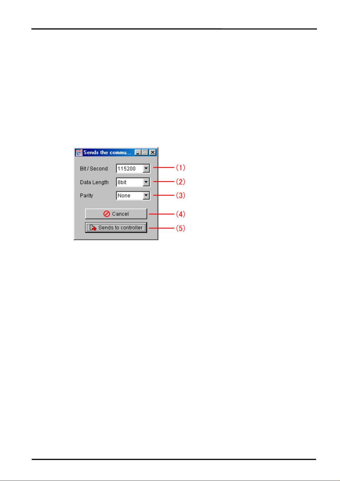
- Communications Change
The communication conditions of the controller can be changed.
< Note >
* When the communication setting transmission is done, the measurement conditions
setting of the controller is transmitted with the transmission setting contents, and stored in
the controller.
* When this communication setting transmission is desired to implement, turn off the
controller once and turn it on again. Unless doing so, the setting is not reflected.
(1) Bit / Second
Select 9600, 19200, 38400, or 115200 bps to specify the communication speed (baud
rate).
< Reference > Default Setting: 115200 bps
(2) Data Length
Select 7bit or 8bit to specify the data length.
< Reference > Default Setting: 8 bit
(3) Parity
Select Even, Odd, or None to enable parity check.
< Reference > Default Setting: None
3-3
Page 14

(4) Cancel
The data set by this diagram will not be set on the HL-C1 controller, and the screen will
return to the Main screen.
(5) Sends to controller
The data set by this diagram will be sent to the HL-C1 controller, and set on the
controller.
If the set data is sent to the controller, the data will be stored in the controller.
3-1-3 System Menu
- Communications Setup
Sets the communication conditions of the PC.
< Note >
The transmission cannot be done if the communication conditions setting of the controller
does not match the transmission setting of the PC.
Communication Setup
Operation Setup
CSV Setting
Emitted Light Amount Search
3-4
Page 15

(1) COM Port
For the COM port, select a port to be used for serial communication between the PC
and the controller.
(2) Bit / Second
Select 9600, 19200, 38400, or 115200 bps to specify the communication speed (baud
rate).
< Reference > Default Setting: 115200 bps
(3) Data Length
Select 7bit or 8bit to specify the data length.
< Reference > Default Setting: 8 bit
(4) Parity
Select Even, Odd, or None to enable parity check.
< Reference > Default Setting: None
(5) Time Out
After sending a command, the HL-C1AiM should wait for a while to receive the
response. Set this wait time for the HL-C1AiM.
Select 1sec, 2sec, 3sec, 5sec, or 10sec to activate the time-out function.
< Reference > Default Setting: 3 sec
(6) BCC
For BCC (Block Check Code) calculation, specify which type of data should be attached
to the BCC of the send/receive message; calculation results or dummy code.
(7) Initialize
Erases all the set data, and resets to the factory-set initial status.
When initialized, the data is reset to the initial status, but this data is not yet saved. To
retain the initialized status even after power-off, execute "Save".
< List of default values >
COM Port : COM1 (The default value depends on the PC used for operation.)
Bit / Second : 115200 bps
Data Length : 8 bit
Parity : None
Time Out : 3 sec
(8) OK
Sets the results of change.
3-5
Page 16

(9) Cancel
Cancels the change.
- Operation Setup
Sets operation of the HL-C1AiM depending on the capability of your PC.
(1) Display Frequency (Measurement Graph)
For the graphs of Measurement Data Monitor, the graph update intervals will be set in
the range of 40 to 200ms.
< Note >
This value depends on the processing performance of the PC and the application
programs simultaneously operated. For this reason, this value may differ from the set
value.
(2) Hi / Lo Limit Bar Display (Measurement Graph)
Displays the set upper/lower limit value in the Measurement Data Monitor graph.
(3) Alarm / Output Bar Display (Measurement Graph)
Displays the alarm output status (alarm output vs. time) on the Measurement Data
Monitor screen. If it is difficult to read the graph due to the overlapped waveforms,
change the display position to upper, middle, or lower area.
3-6
Page 17

(4) Communications Priority
The priority of signal transmission process for the controller and PC is set under
Windows control.
(5) Communications Frequency
Specify the CPU time assigned by Windows for the transmission/reception process.
Select "Low" Communications Frequency to acquire data from the controller less often.
Select "Standard (default)" for regular operation. If transmission/reception is unstable
due to the environment of the PC, select "Low".
(6) Display Frequency (Intensity Graph)
You can set the graph update intervals for the Intensity Monitor graph in the range of
400 to 1000ms.
< Reference > Default Setting: 500ms
(7) Graph Rectangle Display (Intensity Graph)
Displays the Intensity Monitor graph by the rectangular waveform.
(8) Close
Closes this Operation Setup window.
- CSV Setting
Can set a value separator and decimal separator of CSV file.
3-7
Page 18

(1) Value Separator
Please select a character to divide each cell data.
Separate cell data by selected character when output a CSV file.
< Note >
The same character must be used for an opened CSV file.
(2) Decimal Separator
Please select a decimal point character of numeric data.
Used a selected character when output a CSV file.
< Note >
The same character must be used for an opened CSV file.
(3)OK
Closed a screen.
After this, selection contents are reflected by CSV file operation.
(4) CANCEL
Closed a screen.
CSV setting is not changed.
- Emitted Light Amount Search
At the moment that this function was selected, the emitting light amount is adjusted such
that the receiving light amount for the set measuring surface is to be suitable.
The emitted light amount search function can only be used with the GS controller.
Refer to the “Chapter 3-6 Emitted Light Amount Search”.
3-8
Page 19

3-1-4 Help Menu
- Help
Activates the help file.
- About HL-C1AiM
Shows the version number of this software.
3-9
Page 20

3-2 Main Display
(1) Online Button
Use this button to start communication control for measurement.
Each time you click this button, the status of the button will be changed as follows:
If the word "Online" is red, the system is now communicating with the controller.
(2) Controller Version
Shows the program version number of the controller connected to this software.
< Supplementary Explanation >
* The controller version number cannot be changed in the Online mode (the word
"Online" is red).
(3) Product Code
Shows the product code of the controller connected to this software.
< Supplementary Explanation >
* The controller product code cannot be changed during online operation (when "Online"
is displayed in red).
3-10
Page 21

(4) Sensor Head 1,2
Displays the type of the Sensor Head connected to the Sensor Head connector of the
controller.
The default values of the following items depend on the type of the Sensor Head:
Upper limit value
Lower limit value
Upper limit hysteresis
Lower limit hysteresis
Analog output setting (+5V side)
Analog output setting (-5V side)
(5) Measurement Value of Sensor Head 1
Displays the measurement value of Sensor Head 1 or value obtained by add/subtract
calculation.
The displayed item depends on the condition set for the Sensor Head operation.
(6) Light Received Data of Sensor Head 1
Displays the peak light received at the measurement point of Sensor Head 1. When
installing the Sensor Head, set enough light received for measurement considering this
peak value.
(7) Measurement Value of Sensor Head 2
Displays the measurement values of Sensor Head 2.
The values will not depend on the conditions set for Sensor Head operation.
(8) Light Received Data of Sensor Head 2
Displays the peak light received obtained at the measurement point of Sensor Head 2.
When installing the Sensor Head, set enough light received for measurement considering
this peak value.
(9) The alarm and the judgment output confirmation
Use this window to check the output alarm and judgment.
White characters mean OFF, and red characters ON.
AL1: Alarm output (Sensor Head 1)
AL2: Alarm output (Sensor Head 2)
O11: Judgment output 1 (Sensor Head 1)
O12: Judgment output 2 (Sensor Head 1)
O21: Judgment output 1 (Sensor Head 2)
O22: Judgment output 2 (Sensor Head 2)
3-11
Page 22

(10) Hold Mode
For this equipment, there are 4 types of hold modes. They are the NORMAL, P-P, PEAK,
and VALLEY modes. The measurement result data will be displayed and output in the set
mode.
For the details of the Hold Mode, refer to the instruction manual of the controller.
(11) Hold
Holds the measurement values displayed on the HL-C1AiM. Use this function to read the
fluctuating measurement values at a certain moment.
Click the button. The word “Hold” will turn into red, and the measurement values will be
held.
(12) Timing
In the timing input status, the judgment output (O1, O2), measurement values, and analog
output value displayed just before will be held. You can set whether the laser emission
should be halted or continued in this status. If it is not necessary to carry out
measurement or judgment, enter this command in order to prevent unnecessary variation
in the output or laser emission.
Click this button. The word "Timing" will turn into red. In this status, the alarm output will
be turned off, and the measurement values and judgment output will be held.
* In the timing input status, the word "Timing" will turn into red.
* Clicking this button again will cancel the timing input status, and the word "Timing" will
turn into black.
For the details of the Timing, refer to the instruction manual of the controller.
< Note >
* If the product code is set to "WL", "TIMING" goes into non-active state and the setting
becomes impossible.
* Before switching the timing function on the HL-C1AiM, check that the timing command is
not input from the terminal. If such a command is input from the terminal, the priority will
be given to the command input from the terminal. For this reason, the HL-C1AiM will
switch the timing input function on the display, but will not switch the function actually.
(13) Zero Set
The displayed displacement value is normally the distance measured from the
measurement center. Entering the "Zero Set" command will display the displacement
value measured from the current position. For this reason, when the zero setting is
performed, the measurement values and analog output value currently displayed will be
set to zero forcibly. Use this function to measure the variation or make judgment whether
the data is in the specified range after setting the measurement value of the reference
workpiece to "0".
3-12
Page 23

Click this button. The word "Zero Set" will turn into red, and the measurement values will be
set to "0".
* If the zero setting is performed, the word "Zero Set" will turn into red.
* Clicking this button again will cancel the zero setting status, and the word "Zero Set" will
turn into black.
For the details of the Zero Set, refer to the instruction manual of the controller.
< Note >
* Before switching the zero setting function on the HL-C1AiM, check that the zero setting
ON or zero setting OFF command is not input from the terminal. If such a command is
input from the terminal, the priority will be given to the command input from the terminal.
For this reason, the HL-C1AiM will switch the zero setting function on the display, but will
not switch the function actually.
3-3 Measurement Conditions Setting
There are sheets to set the measurement conditions.
* Measurement Setup
* Calibration, Data Processing
* Hi / Lo Limit, Analog Output
* I / O, The Others
There are 4 sheets as shown above.
Set the required items for these sheets.
This setting is not reflected instantly. To reflect it, execute the 'send to controller' in the file
menu.
Furthermore, the measurement conditions to the PC memory can be stored or read by
executing ' save the file' or 'open the file' in the file menu.
For the details of functions of each setting item, refer to the instruction manual of the
controller.
3-13
Page 24

< Supplementary Explanation >
To send various setting data to the controller, specify whether the zero setting data should
be sent.
ON:
Sends the currently displayed offset value to the controller.
The zero setting data set on the controller will be rewritten.
When the setting file is read from the external memory device, and if the displayed zero
set amount is desired to reflect, select this.
OFF:
Sends the zero setting data of 0mm to the controller.
The zero setting data set on the controller will be rewritten.
Current state:
Does not send the zero setting data.
This means that the zero setting data set on the controller will not be rewritten.
< Specular-reflaction-mode and Refraction-factor-calculation >
When changing the setting of the Specular reflaction mode to 'Thickness', the Refraction
factor calculation becomes to ON automatically.
However, in case of changing the setting from 'Thickness', the calculation doesn't become to
OFF automatically.
3-14
Page 25

3-4 Display Waveform of Measurement Value
The data is displayed in accordance with the set measurement value graph renewal interval
(40ms to 200ms) in the software operation setting (Chapter 3-1-3).
(1) Indicator
Loads data on the HL-C1AiM until the indicator is fully loaded.
It can be moved to the desired time axis by dragging the cursor of the indicator.
(2) Graph of Sensor Head 1
Displays the measurement data of Sensor Head 1 or measurement data obtained by
addition/subtraction.
Set the axis range to adjust the display range.
Enlargement method:
If you want to enlarge the display range, drag the mouse from the upper left corner to
the lower right corner to show the desired size.
3-15
Page 26

Undoing method:
In the graph display area, drag the mouse from the lower right to the upper left at any
position.
(3) Graph of Sensor Head 2
Displays the measurement data of Sensor Head 2.
Set the axis range to adjust the display range.
Enlargement method:
If you want to enlarge the display range, drag the mouse from the upper left corner to
the lower right corner to show the desired size.
Undoing method:
In the graph display area, drag the mouse from the lower right to the upper left at any
position.
(4) Vertical Axis Measure
Enter a check mark in the check box to display the measure cursor.
(5) Horizontal Axis Measure
Enter a check mark in the check box to display the measure cursor.
(6) Select Sensor Head
Select a Sensor Head to display the measure cursor.
(7) Vertical Cursor Button to Move (Dotted Line)
Click this button to move the left cursor (dotted line) rightward/leftward. While holding
down the Shift key, click this button to move the cursor at a high speed.
(8) Vertical Cursor Button to Move (Solid Line)
Click this button to move the right cursor (solid line) rightward/leftward. While holding
down the Shift key, click this button to move the cursor at a high speed.
(9) Horizontal Cursor Button to Move (Solid Line)
Click this button to move the top cursor (solid line) upward/downward. While holding down
the Shift key, click this button to move the cursor at a high speed.
(10) Horizontal Cursor Button to Move (Dotted Line)
Click this button to move the bottom cursor (dotted line) upward/downward. While holding
down the Shift key, click this button to move the cursor at a high speed.
(11) Distance between Top and Bottom
Displays the top and bottom cursor positions and their distance data (difference data)
using an absolute value.
3-16
Page 27

< Note >
The relation between the number of dots on the screen and the graph display range may
cause slight difference in the cursor position data. For this reason, use the data as
reference values.
(12) Distance between Right and Left
Displays the right and left cursor positions and their distance data (difference data) using
an absolute value.
< Note >
The relation between the number of dots on the screen and the graph display range may
cause slight difference in the cursor position data. For this reason, use the data as
reference values.
(13) Axis Range
You can adjust the scales of the vertical and horizontal axes of the measurement data
waveform graph.
(14) Axis Range (Vertical Axis)
You can adjust the vertical axis in the range of 999.9 to –999.9mm
In the case of "Standard (Product Code)" setting
< Reference: Default Setting >
50mm type 6.5 to -6.5mm
85mm type 25.0 to -25.0mm
In the case of "GS (Product Code)" setting
< Reference: Default Setting >
25mm type 1.2 to -1.2mm
50mm type 5.0 to -5.0mm
85mm type 20.0 to -20.0mm
In the case of "WL (Product Code)" setting
< Reference: Default Setting >
350mm/320mm 250.0 to -250.0mm
(15) Axis Range (Horizontal Axis)
You can adjust the horizontal axis in the range of 1000 to 9000ms.
< Reference: Default Setting >
8000ms
(16) Initialize
You can reset the set vertical/horizontal axis scale data of the measurement data
waveform graph to the initial data.
3-17
Page 28

In the case of "Standard (Product Code)" setting
< Reference: Default Setting >
50mm type: Vertical Axis 6.5 to -6.5mm, Horizontal Axis 8000ms
85mm type: Vertical Axis 25.0 to -25.0mm, Horizontal Axis 8000ms
In the case of "GS (Product Code)" setting
< Reference: Default Setting >
25mm type: Vertical Axis 1.2 to -1.2mm, Horizontal Axis 8000ms
50mm type: Vertical Axis 5.0 to -5.0mm, Horizontal Axis 8000ms
85mm type: Vertical Axis 20.0 to -20.0mm, Horizontal Axis 8000ms
In the case of "WL (Product Code)" setting
< Reference: Default Setting >
350mm/320mm: Vertical Axis 250.0 to -250.0mm, Horizontal Axis 8000ms
(17) Collect
Loads measurement data from the controller.
(18) Play
Replays measurement data stored in the memory.
(19) Load
Calls out the measurement result data from the storage.
(20) Save
Transfers the measurement result data stored in the memory to the storage.
Data can be stored in the PC using the CSV or MS2 format (format for HL-C1AiM
measurement data waveform only).
The data stored in the CSV format can be directly read out using a spreadsheet program.
If data is stored in the MS2 format, the data can be reloaded and regenerated on the
HL-C1AiM.
(21) File Operation … Print
Open the print dialog box to print measurements or screen image.
(22) File Operation … Save
Save the settings and screen image on the storage media. Settings are saved in a text
document and the screen image is saved as a bitmap or JPEG image.
(23) Close
Closes the measurement data waveform display screen.
3-18
Page 29

3-5 Display Waveform of Light Receive Data
The receiving light state of each head is indicated with the cell position and the receiving
light amount.
< Supplementary Explanation >
* Even after setting the sampling period to 100us, if the waveform of light received data is
being displayed, the sampling period may be prolonged.
* While displaying the waveform of light received data, if you enter the "Initialize controller"
command using the console, the displayed waveform may not be updated.
* Usable functions are limited depending on the product code. The unusable function is that
the component goes into "non-active" state and the setting becomes impossible. Refer to
the "Table 3-1" for details.
* The display of the waveform differs depending on the setting of the product code of the
controller, connected sensor head or number of the displayed cells. Refer to the "Table 3-2"
for details.
3-19
Page 30

(1) Indicator
Loads data on the HL-C1AiM until the indicator is fully loaded.
(2) Graph of Sensor Head 1
Displays the light received of Sensor Head 1.
You can enlarge the display range or reduce the range to the initial size.
Enlargement method:
If you want to enlarge the display range, drag the mouse from the upper left corner to
the lower right corner to show the desired size.
Undoing method:
In the graph display area, drag the mouse from the lower right to the upper left at any
position.
Scrolling method:
Drag the right button of the mouse to scroll the display screen.
(3) Graph of Sensor Head 2
Displays the light received of Sensor Head 2.
You can enlarge the display range or reduce the range to the initial size.
Enlargement method:
If you want to enlarge the display range, drag the mouse from the upper left corner to
the lower right corner to show the desired size.
Undoing method:
In the graph display area, drag the mouse from the lower right to the upper left at any
position.
Scrolling method:
Drag the right button of the mouse to scroll the display screen.
(4) Measurement Value of Sensor Head 1
Displays the measurement result data of Sensor Head 1 or measurement result data
obtained by addition/subtraction.
(5) Peak Cell of Sensor Head 1
Displays the position of the CCD cell receiving maximum light in Sensor Head 1.
1 to 256 if the connected Sensor Head is 25mm type, 50mm type, 1 to 512 if the
connected Sensor Head is 85mm type, 320mm type, 350mm type.
(6) Measurement Value of Sensor Head 2
Displays the measurement result data of Sensor Head 2.
3-20
Page 31

(7) Peak Cell of Sensor Head 2
Displays the position of the CCD cell receiving maximum light in Sensor Head 2.
1 to 256 if the connected Sensor Head is 25mm type, 50mm type, 1 to 512 if the
connected Sensor Head is 85mm type, 320mm type, 350mm type.
(8) Explanation of each sheet
Refer to the Chapter 3-5-1 to 3-5-4.
(9) Replay Function
The receiving light amount data in the memory can be Replay data/ Stop replaying/ Show
data in a forward direction/ Show data in a reverse direction/ Pause replay.
This function is usually not on display. In order to use this function, click the right button of
the mouse on the 'Play button (11)'. If the right button is clicked again, this button will
disappear.
(10) Collect
Loads the light received data from the controller.
(11) Play
Regenerates light received data stored in the memory.
If the right button of the mouse is clicked on the button, the details of Replay Function (9)
is indicated.
Click on the right mouse button again to hide details.
(12) Close
Closes the light received data waveform display screen.
3-21
Page 32

3-22
Page 33

3-5-1 “Head 1 Setting” Tab Sheet
On the sheet where the measurement conditions of the head 1 are set, the following setting
is possible.
* Specular Reflection Mode
* Measurement Surface Selection
* Detection Level Setting
* Simplified Optical Filter
* Emitted Light Adjustment
* Emitted Light Amount Search
Since this measurement condition setting is the same as the measurement condition setting
on the main screen, a head adjustment can be done only with the receiving light amount
waveform screen, without using the measurement condition setting on the main screen
(Chapter 3-3).
Note that these setting is not reflected instantly. To reflect them, click the 'Send' button.
For the details of the functions of each setting item, refer to the instruction manual of the
controller. Furthermore, for the emitting light amount search, refer to the Chapter 3-6 in this
instruction manual.
3-23
Page 34

3-5-2 “Head 2 Setting” Tab Sheet
On the sheet where the measurement conditions of the head 2 are set, the following setting
is possible.
* Specular Reflection Mode
* Measurement Surface Selection
* Detection Level Setting
* Simplified Optical Filter
* Emitted Light Adjustment
* Emitted Light Amount Search
Since this measurement condition setting is the same as the measurement condition setting
on the main screen, a head adjustment can be done only with the receiving light amount
waveform screen, without using the measurement condition setting on the main screen
(Chapter 3-3).
Note that these setting is not reflected instantly. To reflect them, click the 'Send' button.
For the details of the functions of each setting item, refer to the instruction manual of the
controller. Furthermore, for the emitting light amount search, refer to the Chapter 3-6 in this
instruction manual.
3-24
Page 35

3-5-3 “Chart Setting” Tab Sheet
This is a sheet to set the graph display. (This setting can only be used with the GS
controller.)
(1) Number of Displayed Cells
The number of displayed cells setting can only be used with the GS controller.
The number of cells displayed on the light received waveform screen can be selected in
the range from 101 to 256 cells.
< Supplementary Explanation >
* With the "Standard (Product Code)" setting, the number is fixed at 101 cells.
(2) Surface Number Display
The surface number display setting can only be used with the GS controller.
After the surface number display is selected, the peak light received amount is indicated
with a number.
This function is convenient for the measurement surface selection function of the specular
reflection mode.
The number for the selected measurement surface is in red, and the others are in white.
(3) Marker Display
The marker display setting can only be used with the GS controller.
After marker display is selected, the peak light received amount is indicated with a line.
3-25
Page 36

3-5-4 “The Others” Tab Sheet
This is a sheet to set the measurement conditions, Load/ Send the file, and Print/ Save the
data.
(1) Sampling Period
Since this measurement condition setting is the same as the measurement condition
setting on the main screen, a head adjustment can be done only with the receiving light
amount waveform screen, without using the measurement condition setting on the main
screen (Chapter 3-3).
Note that these setting is not reflected instantly. To reflect them, click the 'Send' button.
For the details of the functions of each setting item, refer to the instruction manual of the
controller.
(2) Load
Loads the light received data from the controller.
3-26
Page 37

(3) Save
Transfers the light received data stored in the memory to the storage.
Data can be stored in the PC using the CSV or DW3 format (format for HL-C1AiM light
received waveform only).
The data stored in the CSV format can be directly read out using a spreadsheet program.
If data is stored in the DW3 format, the data can be reloaded and regenerated on the
HL-C1AiM.
< Note >
Any previous version of 3.20 DWD files can be read and executed, too.
Please set CSV with a CSV setting screen when use the CSV file output with AiM.
(4) File Operation … Print
Open the print dialog box to print measurements or screen image.
(5) File Operation … Save
Save the settings and screen image on the storage media. Settings are saved in a text
document and the screen image is saved as a bitmap or JPEG image.
3-27
Page 38

3-6 Emitted Light Amount Search
The emitted light amount search function can only be used with the GS controller.
When 'Execute' button is clicked, this function is immediately implemented, to adjust the
emitted light amount of the selected measurement surface so that the optimum light
received data is obtained. (If two or more surfaces are selected, the smaller amount of
received data for one surface is adjusted to the optimum amount.)
The emitted light amount is adjusted in the setting range of the "Emitted Light Adjustment"
function to between 0.7 and 49%. If adjustment of the emitted light amount in this range fails,
"Automatic" is selected for the Emitted Light Adjustment.
< Supplementary Explanation >
* If two or more surfaces are selected and a search is made of the surface showing the
largest difference as to the reflected light amount (about four times or greater ratio to the
light received data), the "Automatic" emitted light amount may not be selected even if the
emitted light amount search fails. In such a case, check the Intensity Monitor and manually
adjust.
3-28
Page 39

3-7 Display Data Buffering
3-7-1 Data Buffering Procedure
(1) Select a buffering setting item.
(2) Press the "Start" button to start data accumulation.
(3) Monitor the accumulation status, and press the "Stop" button when you want to stop it.
The accumulated data can be read out after stopping accumulation.
(4) In the accumulation data reading area, press the "Head 1" or "Head 2" button to transfer
data from the controller to the PC.
The result will be displayed on the screen using data or waveform.
3-7-2 Display Data Buffering
Before transferring measurement data to PC, you can temporarily accumulate up to 48000
data items in the controller. The accumulated data can be taken from the controller to the
PC.
Use this function to check the measurement data at the time of introduction or to read out or
store all the data after measurement.
Note that the data buffering function may restrict the sampling period.
3-29
Page 40

< Supplementary Explanation >
In this Manual, "accumulation" and "accumulation operation" have different meanings as
described below:
* Accumulation: To store measurement data in the internal memory of the controller.
* Accumulation operation: A series of accumulation operations that include waiting for
trigger, accumulation, and completion of accumulation
(1) Graph of Sensor Head 1
Displays the graph after reading out the accumulated data of Sensor Head 1.
< Supplementary Explanation >
During alarm, the waveform of measurement data may wave to the upper and lower limits
due to the reduced scale of the display area. In this case, however, the data shows the
correct alarm output.
(2) Graph of Sensor Head 2
Displays the graph after reading out the accumulated data of Sensor Head 2.
< Supplementary Explanation >
During alarm, the waveform of measurement data may wave to the upper and lower limits
due to the reduced scale of the display area. In this case, however, the data shows the
correct alarm output.
(3) Line Number
X-axis data of waveform displayed on the left side.
(4) Measurement Value
Y-axis data of waveform displayed on the left side.
< Supplementary Explanation >
* "ALARM" displayed in the measurement data area represents the alarm output. In this
case, '-999.9999' is accumulated as a value.
* In addition, "****" means that the blank data is fixed to "+999".
(5) Indicate the Number of Accumulated Data
Shows the position of the final data newly accumulated by data buffering for Sensor
Head.
3-30
Page 41

(6) Status
The status data shows the accumulation status of the controller when data buffering is
stopped.
The system displays "Trigger Wait", Storing", "Complete", or "Unknown" to inform the
buffering status.
* Trigger Wait:
The system is now waiting for trigger.
* Storing:
During accumulation, the "Stop" command is entered, and buffering is stopped. In the
"Timing & trigger" mode, accumulation is stopped by inputting the timing.
* Complete:
The specified number of data items are accumulated, and accumulation is completed.
* Unknown:
This message will appear if the system is not in the online mode or buffering is not
started.
(7) Switch to Waveform / Data
For each Sensor Head, you can switch the display screen to "Waveform and data" or
"Display waveform only".
(8) Buffering Mode
Select a data accumulation method.
* Initial & continue:
Data accumulation will be started when the Start button is pressed. Data accumulation
will be stopped when the specified quantity of data is accumulated or when the Stop
command is entered.
* Initial & trigger:
The first data that meets the trigger condition will be accumulated. Accumulation
operation will be started when the Start button is pressed, and will be stopped when the
specified quantity of data is accumulated or when the Stop command is entered.
* Latest & trigger:
During accumulation, the final data that meets the trigger condition will be accumulated.
Accumulation operation will be started when the Start button is pressed, and will be
stopped when the Stop command is entered.
* Timing & trigger:
After pressing the Start button, if the timing input (Ton) status is switched to the timing
cancel (Toff) status, accumulation will be started. Accumulation will be stopped if the
status is switched to the timing input (Ton) status, or the Stop command is entered.
After stopping accumulation by switching the status to the timing input (Ton) status, if
the status is set to the timing cancel (Toff) status again, accumulation will be started
from the first data of the accumulated data.
3-31
Page 42

* Latest & continue:
Data accumulation will be started when the Start button is pressed, and will be stopped
when the Stop command is entered. All the data before entering the Stop command will
be accumulated.
(9) Buffering Head
Select a Sensor Head type (type of data to be accumulated) for buffering.
* Head 1: Measurement data of Sensor Head 1
* Head 2: Measurement data of Sensor Head 2
* Heads 1 & 2: Measurement data of Sensor Heads 1 and 2
< Supplementary Explanation >
* If "Head 1" is selected, the data of Sensor Head 1 will be accumulated in the
independent operation mode, but in the add/subtract operation mode, the add/subtract
result data will be accumulated.
(10) Buffer Rate
Sets the data accumulation intervals for the measurement data that is measured in
accordance with the specified sampling period.
Select the buffering rate from "Same as sampling period", "2 : 1", "4 : 1", "8 : 1", "16 : 1",
"32 : 1", "64 : 1", "128 : 1", "256 : 1", "512 : 1", "1024 : 1", "2048 : 1", "4096 : 1", "8192 : 1",
"16384 : 1", and "32768 : 1".
< Supplementary Explanation >
* If you set the buffering rate, all the measurement data can be accumulated. In addition, if
the data does not greatly vary, you can prolong the accumulation intervals and can
accumulate data for a long time.
< Example >
After setting the sampling period to 144us, if the buffering rate is set to "Same as
sampling period", 48000 data items will be accumulated in approximately 6.9 seconds. If
the buffering rate is set to "32768 : 1", 1 data item will be accumulated every 4.7 seconds.
In other words, 48000 data items measured in 62.9 hours will be accumulated.
(11) Specify the Number of Accumulated Data
Specify the number of data items to be accumulated in the range of 1 to (Maximum
accumulation quantity).
The maximum accumulation quantity depends on the selected buffering Sensor Head
type as shown below:
* Head 1 (Sensor Head 1): 48000 data items
* Head 2 (Sensor Head 2): 48000 data items
* Heads 1 & 2 (Sensor Heads 1 and 2): 24000 data items, each
3-32
Page 43

< Supplementary Explanation >
* In addition, in the "Latest & trigger" mode, the maximum accumulation quantity will be
half of the other trigger mode.
For example, if "Sensor Heads 1 & 2" is selected and the "Latest & trigger" mode is set,
the maximum accumulation quantity will be 12000 data items.
* If a quantity larger than the maximum accumulation quantity (depends on the buffering
Sensor Head type) is set, the set quantity will be displayed in red.
If a quantity smaller than 6000 is set, the trigger point will be temporarily set to the
corresponding accumulation quantity again.
(12) Trigger Point
Sets the trigger point.
* Specify the positional relation between the accumulated data and trigger.
* This function can be used in the "Initial & trigger" mode and the "Latest & trigger" mode
only.
This function will not be valid in the "Timing & trigger" mode.
* The setting range is from 1 to (Set accumulation quantity).
* To accumulate data measured before trigger point: Set the trigger point to the backward
area of the accumulated data.
* To accumulate data measured near trigger point: Set the trigger point to the center area
of the accumulated data.
* To accumulate data measured after trigger point: Set the trigger point to the forward
area of the accumulated data.
(13) Trigger Condition
Select trigger conditions for initial trigger and latest trigger.
* When out of range:
Triggered when entering the range specified by the upper and lower limit value
* When in range:
Triggered when entering the range specified by the upper and lower limit values
* When crossing range:
Triggered when crossing the range specified by the upper and lower limit values
* When alarm is changed: Triggered when the alarm status is changed
(14) Stored Condition
The signal will inform whether each Sensor Head is in the "Accumulating" status
(including the "Waiting for trigger" status) or in the "Accumulation completed" status.
Accumulation status of Sensor Head 1,2:
"Storing" means that data is now being accumulated.
"Complete" means that accumulation is completed or stopped by the "Stop" command.
3-33
Page 44

(15) Start
Starts data buffering (data accumulation).
(16) Stop
Stops data buffering (data accumulation).
(17) Reads the Stored Data
Reads out data accumulated by buffering, and temporarily loads the data in the controller .
(18) Loading Mode
The loading mode can be chosen among "Normal," "High Speed" using a radio button.
Normal loading mode:
The accumulated data is read with normal speed.
High-speed loading mode:
The accumulated data is read with high speed. The reading time changes depending
on the data, since high-speed reading is achieved by reading the difference between
data.
(19) Load
Reads out the CSV format data stored in the PC.
<Note>
Only the CSV file which output with a buffering screen of HL-C1AiM is readable.
(20) Save
Transfers the data buffering result data from the memory to the storage.
The HL-C1AiM can save data in the PC using the CSV format.
The data stored in the CSV format can be directly read out using a spreadsheet program.
Data can be read into the HL-C1AiM again.
<Note>
* Please set CSV with a CSV setting screen when use the CSV file output with AiM.
CSV may not be available if you do not setting.
< Supplementary Explanation >
* In the "Initial & trigger" mode or the "Latest & trigger" mode, if the trigger condition is met
before accumulating all the data specified by the trigger point, dummy data "+999.9999"
will be displayed in the no data area (from the top of the memory to the accumulation start
point) so that this dummy data can be distinguished from the accumulated data.
3-34
Page 45

(21) Trace End
Ends data buffering.
Enters the non-buffering mode, and stops data buffering.
When ended, operation will not be restricted by the shortest sampling period of 144us.
(22) Close
Closes the data buffering display screen.
(23) Load from Controller
Loads the set conditions from the controller.
3-35
Page 46

3-8 Initialize
Initialize the set contents in HL-C1AiM.
In the case of "Standard (Product Code)" setting
< List of default values >
Hold Mode : NORMAL
Sampling Period : 144us
Head Operation : Independent operation
Measurement Mode : Diffused reflection
Specular Reflection Mode : Standard
Emitted Light Adjustment : Automatic
Independent Calculation : L1 + K1A, L2 + K2B
Add/Subtract Calculation : L + K (A + B)
Independent Calculation Offset (L1, L2) : 0.0000mm
Add/Subtract Calculation Offset (L) : 0.0000mm
Independent Calculation Coefficient (K1, K2) : 1.0000
Add/Subtract Calculation Coefficient (K) : 1.0000
Zero Set : Current state
Span : 1.0000
Shift : 0.0000mm
Low Pass Filter : OFF
High Pass Filter : OFF
Simplified Optical Filter : OFF
Average Number : 64 times
Upper Limit Value : +5.0000mm (50mm type)
+20.0000mm (85mm type)
Lower Limit Value : -5.0000mm (50mm type)
-20.0000mm (85mm type)
Upper Limit Hysteresis : 0.0100mm (50mm type)
0.0300mm (85mm type)
Lower Limit Hysteresis : 0.0100mm (50mm type)
0.0300mm (85mm type)
Analog Output (+5V Value) : +5.0000mm (50mm type)
+20.0000mm (85mm type)
Analog Output (-5V Value) : -5.0000mm (50mm type)
-20.0000mm (85mm type)
3-36
Page 47

Judgment Output Selection : LOW, HIGH
Timing Input Operation : Short-Circuit
Laser Emission Control : Halt
Laser Emission Delay : OFF
Input Mode : Independent input
Analog Output During Alarm : Hold
Fixed Analog Output Value During Alarm : maximum +10.9V
Analog Alarm Delay Times : OFF
Analog Alarm Delay : OFF
Output Mode : Normal
Interference Prevention : OFF
CS/DR Control During Accumulation : Yes
In the case of "GS (Product Code)" setting
< List of default values >
Hold Mode : NORMAL
Sampling Period : 498us (85mm type)
332us (50mm type or 25mm type)
Head Operation : Independent operation
Measurement Mode : Specular reflection
Specular Reflection Mode : Front
Surface Selection : 1st Surface
Detection Level Setting : Level 1
Emitted Light Adjustment : Automatic
Independent Calculation : L1 + K1A, L2 + K2B
Add/Subtract Calculation : L + K (A + B)
Independent Calculation Offset (L1, L2) : 0.0000mm
Add/Subtract Calculation Offset (L) : 0.0000mm
Independent Calculation Coefficient (K1, K2) : 1.0000
Add/Subtract Calculation Coefficient (K) : 1.0000
Zero Set : Current state
Span : 1.0000
Shift : 0.0000mm
Low Pass Filter : OFF
High Pass Filter : OFF
Simplified Optical Filter : OFF
Calculation of Refraction Factor : OFF
Refraction Factor : 1.5500
Average Number : 256 times
3-37
Page 48

Upper Limit Value : +16.0000mm (85mm type)
+4.0000mm (50mm type)
+1.0000mm (25mm type)
Lower Limit Value : -16.0000mm (85mm type)
-4.0000mm (50mm type)
-1.0000mm (25mm type)
Upper Limit Hysteresis : 0.0300mm (85mm type)
0.0100mm (50mm type)
0.0030mm (25mm type)
Lower Limit Hysteresis : 0.0300mm (85mm type)
0.0100mm (50mm type)
0.0030mm (25mm type)
Analog Output (+5V Value) : +16.0000mm (85mm type)
+4.0000mm (50mm type)
+1.0000mm (25mm type)
Analog Output (-5V Value) : -16.0000mm (85mm type)
-4.0000mm (50mm type)
-1.0000mm (25mm type)
Judgment Output Selection : LOW, HIGH
Timing Input Operation : Short-Circuit
Laser Emission Control : Halt
Laser Emission Delay : OFF
Input Mode : Independent input
Analog Output During Alarm : Hold
Fixed Analog Output Value During Alarm : maximum +10.9V
Analog Alarm Delay Times : OFF
Analog Alarm Delay : OFF
Output Mode : Normal
Interference Prevention : OFF
CS/DR Control During Accumulation : Yes
3-38
Page 49

In the case of "WL (Product Code)" setting
< List of default values >
Hold Mode : NORMAL
Sampling Period : 100us
Head Operation : Independent operation
Measurement Mode : Diffused reflection
Emitted Light Adjustment : Automatic
Independent Calculation : L1 + K1A, L2 + K2B
Add/Subtract Calculation : L + K (A + B)
Independent Calculation Offset (L1, L2) : 0.0000mm
Add/Subtract Calculation Offset (L) : 0.0000mm
Independent Calculation Coefficient (K1, K2) : 1.0000
Add/Subtract Calculation Coefficient (K) : 1.0000
Zero Set : Current state
Span : 1.0000
Shift : 0.0000mm
Low Pass Filter : OFF
High Pass Filter : OFF
Simplified Optical Filter : OFF
Average Number : 512 times
Upper Limit Value : +200.0000mm (350mm type)
: +150.0000mm (320mm type)
Lower Limit Value : -200.0000mm (350mm type)
: -150.0000mm (320mm type)
Upper Limit Hysteresis : 0.3000mm
Lower Limit Hysteresis : 0.3000mm
Analog Output (+5V Value) : +200.0000mm (350mm type)
: +150.0000mm (320mm type)
Analog Output (-5V Value) : -200.0000mm (350mm type)
: -150.0000mm (320mm type)
Judgment Output Selection : LOW, HIGH
Laser Emission Delay : ON
Analog Output During Alarm : Hold
Fixed Analog Output Value During Alarm : maximum +10.9V
Analog Alarm Delay Times : OFF
Analog Alarm Delay : OFF
Output Mode : Normal
Interference Prevention : OFF
CS/DR Control During Accumulation : Yes
3-39
Page 50

Chapter 4 Error Message
Page 51

4-1 Dialog Display
During operation of HL-C1AiM, if an error is detected, the following dialog will appear:
In the "Error message" area, the message corresponding to the detected error will appear.
Various error messages, their causes, and remedies are shown below:
Error messages:
* COM port error.
* Transmission/reception re-try over.
* Reception error.
* Occurrence of reception time-out.
* Controller version is wrong. Shut down the communication.
* Product code of the controller does not match. Shut down the communication.
* Can not open file.
* Can not create file.
4-2 Error Message
4-2-1 COM port error
Error message
COM port error
< Cause >
* A wrong COM port is specified on the communication conditions setting screen.
< Remedy >
* Specify the right COM port.
4-2-2 Transmission / reception re-try over
Error message
Transmission / reception re-try over
4-1
Page 52

< Cause >
* The power of the controller is off.
* A wrong COM port is specified on the communication conditions setting screen.
* The controller is not connected to the connected COM port.
* The time-out value set on the communication condition setting screen is too short.
< Remedy >
* Turn on the power of the controller.
* Specify the right COM port.
* Connect the controller.
* Set a longer time-out value.
4-2-3 Reception error
Error message
Reception error
< Cause >
* The data is destroyed by the electric noise.
< Remedy >
* Eliminate the electric noise.
4-2-4 Occurrence of reception time-out
Error message
Occurrence of reception time-out
< Cause >
* The controller needs too much time to transfer data.
* The data is destroyed by the electric noise.
< Remedy >
* Set a longer time-out value.
* Eliminate the electric noise.
4-2-5 Controller version is wrong
Error message
Controller version is wrong. Shut down the communication
< Cause >
* The connected controller has a wrong version number.
4-2
Page 53

< Remedy >
* Specify the right controller version number.
4-2-6 Product code of the controller does not match
Error message
Product code of the controller does not match.
Shut down the communication.
< Cause >
*The product code of the connected controller is incorrect.
< Remedy >
*Designate the correct product code of the controller.
4-2-7 Can not open file
Error message
Can not open file
< Cause >
* The specified file is now being used for the other program.
* The specified file does not exist.
< Remedy >
* Check whether the file is now being used for the other program.
* Check the file name.
4-2-8 Can not create file
Error message
Can not create file
< Cause >
* Writing in the specified directory is inhibited.
* The specified directory does not have enough unused area.
< Remedy >
* Cancel the write inhibition.
* Secure enough unused area.
4-3
 Loading...