

Page 1
HL-C135C-BK10
WIDE RANGE ULTRA HIGH-SPEED LASER DISPLACEMENT SENSOR
CCD Style
Sensor head
HL-C1C-M-WL
Controller
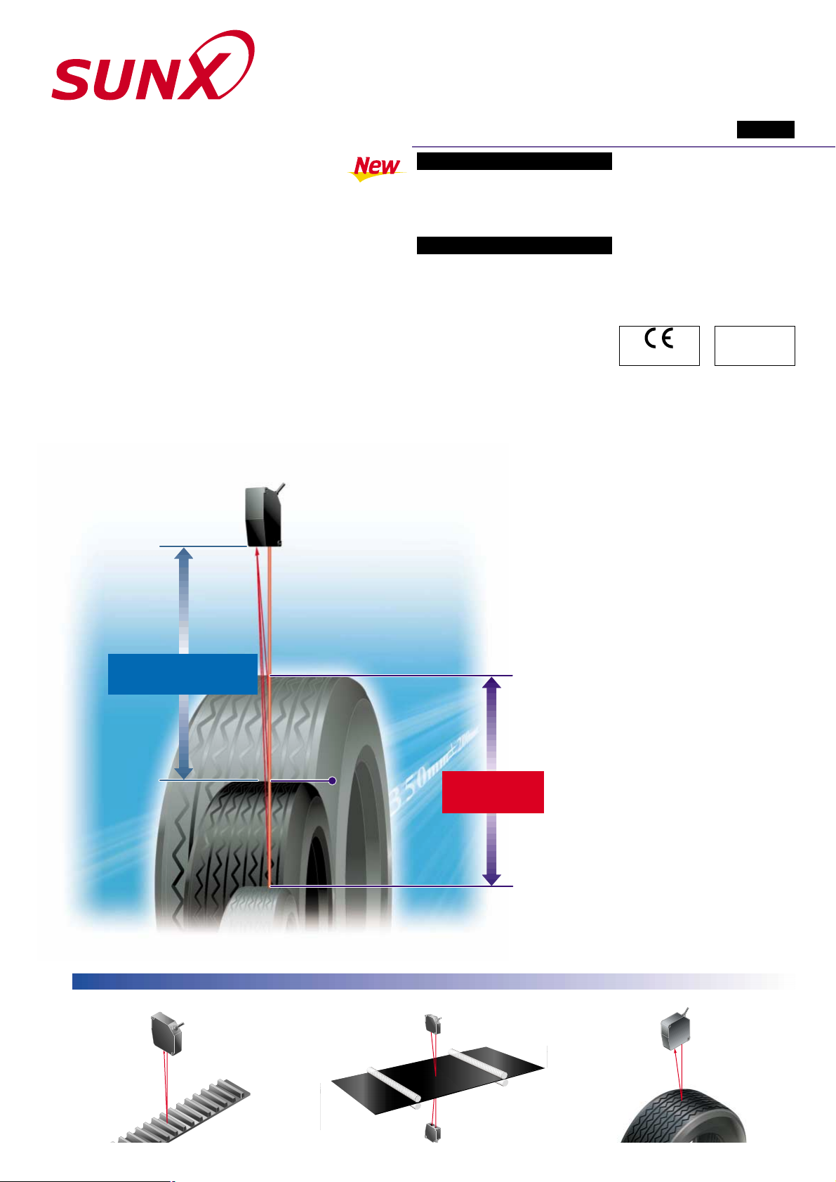
Measures wide changes over
long ranges
The long-and wide-range capabilities over
350 mm 200 mm 13.780 in 7.874 in allow
large changes to be measured. Even if the
object position changes, there is no need to
change the sensor head settings or position.
High speed and high precision
even over long and wide ranges
High-speed and high-precision measurement is possible with high-speed sampling
of 100 !s at a resolution of 10 !m 0.394 mil
an a linearity of 0.1 % F.S.
Improved ease of maintenance
The sensor heads are interchangeable, so
they do not need maintenance as sets. The
protective structure is IP67-rated for
excellent durability.
Peripheral device support for
more stable measurement
The compact controller HL-C1C-M-WL
allows 2 heads to be connected together and
is equipped with a wide variety of functions,
and the monitoring software HL-C1AiM
can be used to provide even greater
precision and stability of measurement.
Industry’s smallest head allows
long and wide range sensing
The development of a unique optical system
has resulted in a head with a size of W26.6
H82D87 mm W1.047H3.228D3.425 in.
This contributes to space savings.
Wide range
200 mm
(7.874 in) !!
Long range
Measurement center
350 mm (13.780 in)
150 mm 5.906 in
550 mm 21.654 in
Center
350 mm mm 13.780 in
150 mm 5.906 in
550 mm 21.654 in
Center
350 mm 13.780 in
Conforming to
EMC Directive
Measuring gap spacing in rubber belt material
Measuring the thickness of rubber sheet Inspecting tire form
Superlative wide-range measurement
with the industry’s smallest head
APPLICATIONS
Conforming to
FDA regulations
Page 2
2431-1 Ushiyama-cho, Kasugai-shi, Aichi,
486-0901, Japan
Phone: +81-(0)568-33-7211
FAX: +81-(0)568-33-2631
SUNX Limited
Phone: +81-(0)568-33-7861
FAX: +81-(0)568-33-8591
Overseas Sales Dept.
http://www.sunx.co.jp/
All information is subject to change without prior notice.
Guide to the intelligent monitor (HL-C1AiM)
An intelligent monitor (sold separately) is available that can be used
for making a variety of measurement condition settings and for
waveform display of each measurement value, as well as monitoring
of measurement data and received light intensity. It can be used to
carry out waveform monitoring that was only previously possible
with a conventional oscilloscope, and can easily be used to set
measurement conditions and functions with the aid of a PC. In
addition, the data can be transferred to a spreadsheet program, so
that inspection data can be processed further and turned into graphs.
Introduction to HL-C1 series variations
The HL-C1 series includes the following in addition to the HL-C135C-BK10
for use in a wide range of applications: 85 mm 20 mm 3.346 in 0.787 in
/ 50 mm 5 mm 1.969 in 0.197 in diffuse reflective type, 81.4 mm
16 mm 3.205 in 0.630 in / 46 mm 4 mm 1.811 in 0.157 in
specular reflective type, and 25 mm 1 mm 0.984 in 0.039 in specular
reflective type which is ideal for glass measurement.
m If using the HL-C1AiM intelligent monitor with an HL-C1C-M-WL
controller, specify a version (3.40 or higher) that is compatible with the
HL-C1C-M-WL controller. Please contact our office for details.
PC (RS-232C)
Controller
HL-C1C-M-WL
Sensor head
HL-C135C-BK10
Extension cable
HL-C1CCJ2 (2 m 6.562 ft)
HL-C1CCJ5 (5 m 16.404 ft)
HL-C1CCJ10 (10 m 32.808 ft)
HL-C1CCJ20 (20 m 65.617 ft)
HL-C1CCJ30 (30 m 98.425 ft)
Compact console
HL-C1DP-E-WL
Intelligent monitor
HL-C1AiM
Intelligent monitor outline specifications
Condition setting function
Measurement data waveform display function
Digital numerical monitoring
Waveform monitoring
Configurator function
Data buffering function
This product is not a safety sensor. Its use is not
intended or designed to protect life and prevent body
injury or property damage from dangerous parts of
machinery. It is a normal object detection sensor.
PRECAUTIONS FOR PROPER USE
SPECIFICATIONS
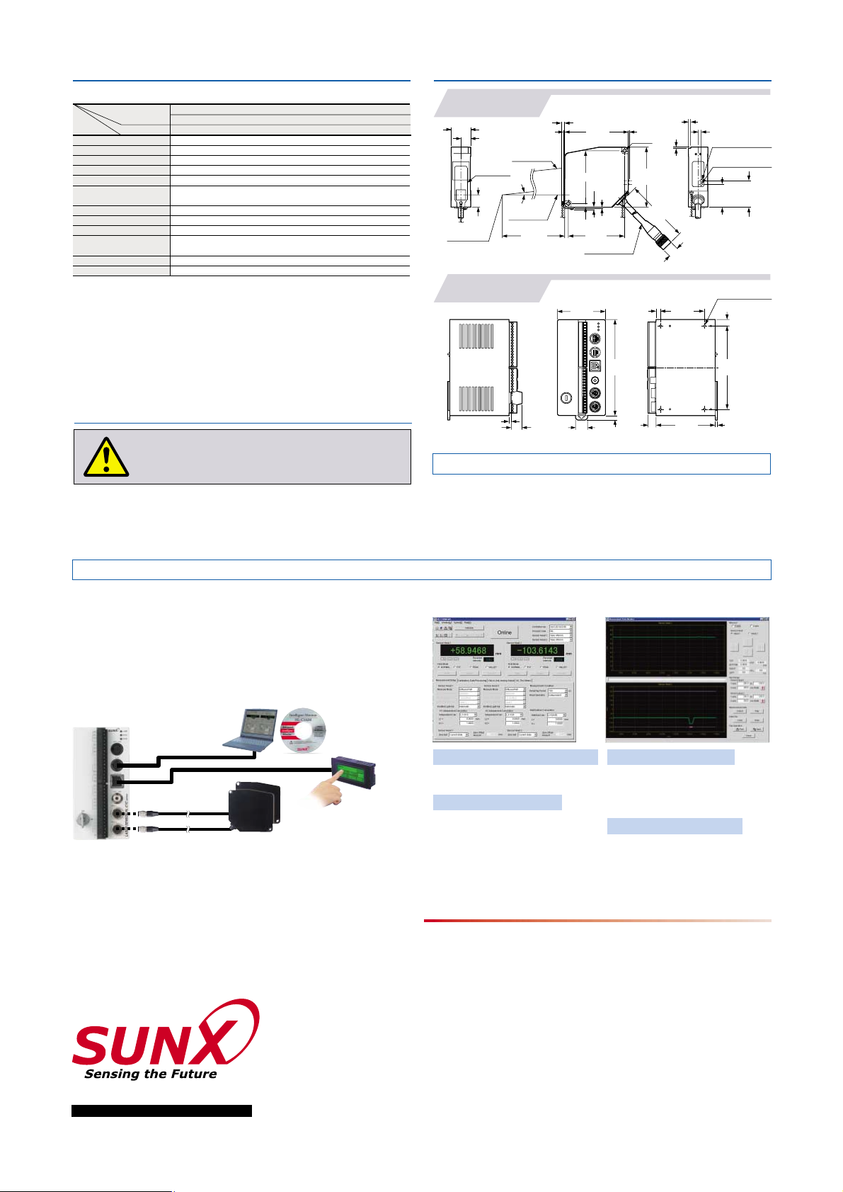
DIMENSIONS (Unit: mm in)
• The laser used in this product corresponds to Class 3B (3b)
laser IEC / FDA / JIS standards. Do not allow the laser to enter
your eye directly or after being reflected. Handle the product by
following the instructions given on the warning labels.
Laser radiation
HL-C135C-BK10
Sensor head
HL-C1C-M-WL
Controller
200 mm 7.874 in
Sensor heads
Diffuse reflective type
350 mm 13.780 in
10 !m 0.394 mil (Note 3)
0.1 % F.S.
0.02 % F.S./C
300 g approx.
Cabtyre cable, 0.5 m 1.640 ft long with connector
IP67 (IEC) (excluding the connector)
IEC / FDA / JIS standards conforming type
HL-C135C-BK10
Linear image sensor
400
200!m 15.7487.874 mil approx.
Notes: 1)
2)
3)
4)
5)
6)
Where measurement conditions have not been specified precisely, the conditions used were as follows: supply voltage 24 V DC,
ambient temperature 20 C 68 F, sampling rate 100 !s, average number of samples: 512, measurement center distance,
object measured is made of white ceramic. Linearity also depends upon the characteristics of the object being measured.
This value is obtained by converting P-P values into a distance. The P-P values indicate the
distribution of measured values throughout the measurement center distance.
This value is obtained with sampling rate 100!s, average number of samples: 512, when using an
object made of our company’s standard white ceramic for measurement.
This value indicates the range of errors for an ideal linear displacement output, when using an object made of our company’s
standard white ceramic for measurement. This value may fluctuate depending on the characteristics of the object measured.
This value is defined by using 1/e2 (13.5 %) of the center light intensity. If there is a slight leakage
of light outside the normal spot diameter and if the periphery surrounding the sensing point has a
higher reflectivity than the sensing point itself, then the results may be affected.
The HL-C1C-M-WL controller and an HL-C1DP-E-WL console specifications are the same as for the HL-C1C-M
controller and HL-C1DP-E console. See the HL-C1 series catalog or the sensor general catalog 2003-2004 for details.
4-M3,
depth: 1.5 0.059
5.5
0.217
13.2
0.520
3 0.118
15
0.591
10
0.394
2.7
0.106
(8.1 0.319)
5.5
0.217
4.15 0.163
3.3 0.130
5
0.197
6
(1.5 0.059)
(4.7 0.185)
(1.4 0.055)
Beam
attenuator
(3.6 0.142)
(1.5 0.059)
13.3
0.524
36.2
1.425
31.2
1.228
26.6
1.047
16.9 0.665
"14.7
"0.579
"7 "0.276 cable
72 2.835
5 0.197
Beam
emitting axis
Beam
receiving axis
2-M5
Laser emission indicator
(Green)
Measuring range indicator
(Yellow)
Measurement
center
0.3
0.012
Type
Model No.Item
Measurement center distance
Measuring range
Resolution (Note 2)
Linearity (Note 4)
Temperature characteristics
Emitting element
Beam diameter (Note 5)
Receiving element
Protection
Ambient temperature
Cable
Weight
No. PCE-HLC135C January, 2004
The CAD data in the dimensions can be downloaded
from SUNX website: http://www.sunx.co.jp/
87
3.425
•
Waveform data collection, storage,
and reading
Measurement value and received light
intensity data waveform monitoring
()
•
Measurement value and received
light intensity data monitoring
• • Setting, storage, and reading of
each condition
Setting, storage, and reading of
each function
•
Accumulation of measurement data
•
Correspond to Microsoft Excel
350
13.780
77
3.031
82
3.228
530
20.866
( )
60
2.362
120
4.724
( )
55
2.165
( )
74
2.913
104
4.094
Red semiconductor laser, Class 3B (Class 3b for FDA standards)
(max. output: 10 mW, peak emission wavelength: 685 nm 0.027 mil)
0 to45 C 32 to113 F (No dew condensation)
Storage:
20 to70 C 4 to158 F
 Loading...