

Page 1

INSTRUCTION MANUAL
Ultra High-speed Laser Displacement Sensor (CCD Style)
HL-C1 series
ME-HLC1 No.0296-00
Page 2

Contents
Cautions on Safety 㨯㨯㨯㨯㨯㨯㨯㨯㨯㨯㨯㨯㨯㨯㨯㨯㨯㨯㨯㨯㨯㨯㨯㨯㨯㨯㨯㨯㨯㨯㨯㨯㨯㨯㨯㨯㨯㨯㨯㨯1
Cautions on Handling Laser Light 㨯㨯㨯㨯㨯㨯㨯㨯㨯㨯㨯㨯㨯㨯㨯㨯㨯㨯㨯㨯㨯㨯㨯㨯㨯㨯2
Correct Handling 㨯㨯㨯㨯㨯㨯㨯㨯㨯㨯㨯㨯㨯㨯㨯㨯㨯㨯㨯㨯㨯㨯㨯㨯㨯㨯㨯㨯㨯㨯㨯㨯㨯㨯㨯㨯㨯㨯㨯㨯㨯㨯9
Warranty㨯㨯㨯㨯㨯㨯㨯㨯㨯㨯㨯㨯㨯㨯㨯㨯㨯㨯㨯㨯㨯㨯㨯㨯㨯㨯㨯㨯㨯㨯㨯㨯㨯㨯㨯㨯㨯㨯㨯㨯㨯㨯㨯㨯㨯㨯㨯㨯㨯13
CHAPTER 1 NAMES AND FUNCTIONS OF PARTS
1-1 Controller 㨯㨯㨯㨯㨯㨯㨯㨯㨯㨯㨯㨯㨯㨯㨯㨯㨯㨯㨯㨯㨯㨯㨯㨯㨯㨯㨯㨯㨯㨯㨯㨯㨯㨯㨯㨯㨯㨯㨯㨯㨯㨯㨯 1-1
1-2 Sensor Head㨯㨯㨯㨯㨯㨯㨯㨯㨯㨯㨯㨯㨯㨯㨯㨯㨯㨯㨯㨯㨯㨯㨯㨯㨯㨯㨯㨯㨯㨯㨯㨯㨯㨯㨯㨯㨯㨯㨯㨯 1-3
1-3 Compact Console 㨯㨯㨯㨯㨯㨯㨯㨯㨯㨯㨯㨯㨯㨯㨯㨯㨯㨯㨯㨯㨯㨯㨯㨯㨯㨯㨯㨯㨯㨯㨯㨯㨯㨯㨯 1-5
CHAPTER 2 INSTALLATION
2-1 System Configuration 㨯㨯㨯㨯㨯㨯㨯㨯㨯㨯㨯㨯㨯㨯㨯㨯㨯㨯㨯㨯㨯㨯㨯㨯㨯㨯㨯㨯㨯㨯㨯㨯 2-1
2-2 Installation Environment and Installation Space 㨯㨯㨯㨯㨯㨯㨯㨯 2-2
2-3 Mounting the Controller 㨯㨯㨯㨯㨯㨯㨯㨯㨯㨯㨯㨯㨯㨯㨯㨯㨯㨯㨯㨯㨯㨯㨯㨯㨯㨯㨯㨯㨯㨯 2-3
2-4 Mounting the Sensor Head㨯㨯㨯㨯㨯㨯㨯㨯㨯㨯㨯㨯㨯㨯㨯㨯㨯㨯㨯㨯㨯㨯㨯㨯㨯㨯㨯 2-4
2-5 Mounting the Compact Console 㨯㨯㨯㨯㨯㨯㨯㨯㨯㨯㨯㨯㨯㨯㨯㨯㨯㨯㨯㨯㨯 2-11
Contents
CHAPTER 3 INPUT AND OUTPUT TERMINAL BLOCKS
3-1 Wiring Terminal Blocks 㨯㨯㨯㨯㨯㨯㨯㨯㨯㨯㨯㨯㨯㨯㨯㨯㨯㨯㨯㨯㨯㨯㨯㨯㨯㨯㨯㨯㨯㨯 3-1
3-2 Output Terminals 㨯㨯㨯㨯㨯㨯㨯㨯㨯㨯㨯㨯㨯㨯㨯㨯㨯㨯㨯㨯㨯㨯㨯㨯㨯㨯㨯㨯㨯㨯㨯㨯㨯㨯㨯㨯 3-3
3-3 Input Terminals㨯㨯㨯㨯㨯㨯㨯㨯㨯㨯㨯㨯㨯㨯㨯㨯㨯㨯㨯㨯㨯㨯㨯㨯㨯㨯㨯㨯㨯㨯㨯㨯㨯㨯㨯㨯㨯㨯 3-5
3-4 Wiring Power Supply 㨯㨯㨯㨯㨯㨯㨯㨯㨯㨯㨯㨯㨯㨯㨯㨯㨯㨯㨯㨯㨯㨯㨯㨯㨯㨯㨯㨯㨯㨯㨯㨯 3-7
3-5 Grounding 㨯㨯㨯㨯㨯㨯㨯㨯㨯㨯㨯㨯㨯㨯㨯㨯㨯㨯㨯㨯㨯㨯㨯㨯㨯㨯㨯㨯㨯㨯㨯㨯㨯㨯㨯㨯㨯㨯㨯㨯㨯㨯 3-8
CHAPTER 4 MEASUREMENT
4-1 Basic Compact Console Operation 㨯㨯㨯㨯㨯㨯㨯㨯㨯㨯㨯㨯㨯㨯㨯㨯㨯㨯㨯㨯 4-1
4-2 Measuring Height㨯㨯㨯㨯㨯㨯㨯㨯㨯㨯㨯㨯㨯㨯㨯㨯㨯㨯㨯㨯㨯㨯㨯㨯㨯㨯㨯㨯㨯㨯㨯㨯㨯㨯㨯㨯 4-5
4-3 Measuring Thickness 㨯㨯㨯㨯㨯㨯㨯㨯㨯㨯㨯㨯㨯㨯㨯㨯㨯㨯㨯㨯㨯㨯㨯㨯㨯㨯㨯㨯㨯㨯㨯㨯 4-7
CHAPTER 5 FUNCTION ITEMS
5-1 Functions 㨯㨯㨯㨯㨯㨯㨯㨯㨯㨯㨯㨯㨯㨯㨯㨯㨯㨯㨯㨯㨯㨯㨯㨯㨯㨯㨯㨯㨯㨯㨯㨯㨯㨯㨯㨯㨯㨯㨯㨯㨯㨯㨯 5-1
5-2 Explanation of Functions 㨯㨯㨯㨯㨯㨯㨯㨯㨯㨯㨯㨯㨯㨯㨯㨯㨯㨯㨯㨯㨯㨯㨯㨯㨯㨯㨯㨯㨯 5-2
5-2-1 Measurement Display 㨯㨯㨯㨯㨯㨯㨯㨯㨯㨯㨯㨯㨯㨯㨯㨯㨯㨯㨯㨯㨯㨯㨯㨯㨯㨯㨯㨯㨯㨯㨯㨯㨯 5-2
5-2-2 Hold Mode 㨯㨯㨯㨯㨯㨯㨯㨯㨯㨯㨯㨯㨯㨯㨯㨯㨯㨯㨯㨯㨯㨯㨯㨯㨯㨯㨯㨯㨯㨯㨯㨯㨯㨯㨯㨯㨯㨯㨯㨯㨯㨯 5-3
5-2-3 Zero Set 㨯㨯㨯㨯㨯㨯㨯㨯㨯㨯㨯㨯㨯㨯㨯㨯㨯㨯㨯㨯㨯㨯㨯㨯㨯㨯㨯㨯㨯㨯㨯㨯㨯㨯㨯㨯㨯㨯㨯㨯㨯㨯㨯㨯 5-5
5-2-4 Timing 㨯㨯㨯㨯㨯㨯㨯㨯㨯㨯㨯㨯㨯㨯㨯㨯㨯㨯㨯㨯㨯㨯㨯㨯㨯㨯㨯㨯㨯㨯㨯㨯㨯㨯㨯㨯㨯㨯㨯㨯㨯㨯㨯㨯㨯㨯 5-6
5-2-5 Display Hold 㨯㨯㨯㨯㨯㨯㨯㨯㨯㨯㨯㨯㨯㨯㨯㨯㨯㨯㨯㨯㨯㨯㨯㨯㨯㨯㨯㨯㨯㨯㨯㨯㨯㨯㨯㨯㨯㨯㨯㨯㨯 5-7
5-2-6 Sampling Period 㨯㨯㨯㨯㨯㨯㨯㨯㨯㨯㨯㨯㨯㨯㨯㨯㨯㨯㨯㨯㨯㨯㨯㨯㨯㨯㨯㨯㨯㨯㨯㨯㨯㨯㨯㨯㨯㨯 5-8
5-2-7 Sensor Head Operation 㨯㨯㨯㨯㨯㨯㨯㨯㨯㨯㨯㨯㨯㨯㨯㨯㨯㨯㨯㨯㨯㨯㨯㨯㨯㨯㨯㨯㨯㨯 5-10
5-2-8 Calculation Formulas㨯㨯㨯㨯㨯㨯㨯㨯㨯㨯㨯㨯㨯㨯㨯㨯㨯㨯㨯㨯㨯㨯㨯㨯㨯㨯㨯㨯㨯㨯㨯㨯㨯 5-11
5-2-9 Emission Adjustment 㨯㨯㨯㨯㨯㨯㨯㨯㨯㨯㨯㨯㨯㨯㨯㨯㨯㨯㨯㨯㨯㨯㨯㨯㨯㨯㨯㨯㨯㨯㨯㨯㨯 5-13
Page 3

Contents
5-2-10 Measurement Mode 㨯㨯㨯㨯㨯㨯㨯㨯㨯㨯㨯㨯㨯㨯㨯㨯㨯㨯㨯㨯㨯㨯㨯㨯㨯㨯㨯㨯㨯㨯㨯㨯 5-14
5-2-11 Specular Reflection Mode㨯㨯㨯㨯㨯㨯㨯㨯㨯㨯㨯㨯㨯㨯㨯㨯㨯㨯㨯㨯㨯㨯㨯㨯㨯㨯㨯 5-16
5-2-12 Interference Prevention 㨯㨯㨯㨯㨯㨯㨯㨯㨯㨯㨯㨯㨯㨯㨯㨯㨯㨯㨯㨯㨯㨯㨯㨯㨯㨯㨯㨯㨯 5-18
5-2-13 Laser Emission Delay 㨯㨯㨯㨯㨯㨯㨯㨯㨯㨯㨯㨯㨯㨯㨯㨯㨯㨯㨯㨯㨯㨯㨯㨯㨯㨯㨯㨯㨯㨯 5-19
5-2-14 Average Number of Samples㨯㨯㨯㨯㨯㨯㨯㨯㨯㨯㨯㨯㨯㨯㨯㨯㨯㨯㨯㨯㨯㨯㨯㨯 5-20
5-2-15 Low Pass Filter 㨯㨯㨯㨯㨯㨯㨯㨯㨯㨯㨯㨯㨯㨯㨯㨯㨯㨯㨯㨯㨯㨯㨯㨯㨯㨯㨯㨯㨯㨯㨯㨯㨯㨯㨯㨯 5-21
5-2-16 High Pass Filter 㨯㨯㨯㨯㨯㨯㨯㨯㨯㨯㨯㨯㨯㨯㨯㨯㨯㨯㨯㨯㨯㨯㨯㨯㨯㨯㨯㨯㨯㨯㨯㨯㨯㨯㨯 5-22
5-2-17 Simplified Optical Filter 㨯㨯㨯㨯㨯㨯㨯㨯㨯㨯㨯㨯㨯㨯㨯㨯㨯㨯㨯㨯㨯㨯㨯㨯㨯㨯㨯㨯㨯 5-23
5-2-18 Upper and Lower Limits and Hysteresis Settings 㨯㨯㨯㨯㨯 5-24
5-2-19 Judgment Output Selection㨯㨯㨯㨯㨯㨯㨯㨯㨯㨯㨯㨯㨯㨯㨯㨯㨯㨯㨯㨯㨯㨯㨯㨯㨯㨯 5-27
5-2-20 Output Mode 㨯㨯㨯㨯㨯㨯㨯㨯㨯㨯㨯㨯㨯㨯㨯㨯㨯㨯㨯㨯㨯㨯㨯㨯㨯㨯㨯㨯㨯㨯㨯㨯㨯㨯㨯㨯㨯㨯 5-28
5-2-21 Analog Output Setting 㨯㨯㨯㨯㨯㨯㨯㨯㨯㨯㨯㨯㨯㨯㨯㨯㨯㨯㨯㨯㨯㨯㨯㨯㨯㨯㨯㨯㨯㨯 5-29
5-2-22 Analog Output During Alarm 㨯㨯㨯㨯㨯㨯㨯㨯㨯㨯㨯㨯㨯㨯㨯㨯㨯㨯㨯㨯㨯㨯㨯㨯 5-31
5-2-23 Analog Alarm Delay 㨯㨯㨯㨯㨯㨯㨯㨯㨯㨯㨯㨯㨯㨯㨯㨯㨯㨯㨯㨯㨯㨯㨯㨯㨯㨯㨯㨯㨯㨯㨯㨯 5-32
5-2-24 Input Selection 㨯㨯㨯㨯㨯㨯㨯㨯㨯㨯㨯㨯㨯㨯㨯㨯㨯㨯㨯㨯㨯㨯㨯㨯㨯㨯㨯㨯㨯㨯㨯㨯㨯㨯㨯㨯㨯 5-34
ع
Input Operation
ع
LD Emission
ع
Two-sensor Head Input Mode
㨯㨯㨯㨯㨯㨯㨯㨯㨯㨯㨯㨯㨯㨯㨯㨯㨯㨯㨯㨯㨯㨯㨯㨯㨯㨯㨯㨯㨯㨯㨯㨯㨯㨯㨯㨯㨯㨯㨯
㨯㨯㨯㨯㨯㨯㨯㨯㨯㨯㨯㨯㨯㨯㨯㨯㨯㨯㨯㨯㨯㨯㨯㨯㨯㨯㨯㨯㨯㨯㨯㨯㨯㨯㨯㨯㨯㨯㨯㨯㨯
㨯㨯㨯㨯㨯㨯㨯㨯㨯㨯㨯㨯㨯㨯㨯㨯㨯㨯㨯㨯㨯㨯㨯㨯㨯
5-2-25 Calibration 㨯㨯㨯㨯㨯㨯㨯㨯㨯㨯㨯㨯㨯㨯㨯㨯㨯㨯㨯㨯㨯㨯㨯㨯㨯㨯㨯㨯㨯㨯㨯㨯㨯㨯㨯㨯㨯㨯㨯㨯㨯 5-36
ع
Automatically Setting the Span and Shift
ع
Direct Input of Span and Shift
㨯㨯㨯㨯㨯㨯㨯㨯㨯㨯㨯㨯㨯㨯㨯㨯㨯㨯㨯㨯㨯㨯㨯㨯㨯
㨯㨯㨯㨯㨯㨯㨯㨯㨯㨯㨯㨯㨯㨯㨯
5-2-26 Light Received 㨯㨯㨯㨯㨯㨯㨯㨯㨯㨯㨯㨯㨯㨯㨯㨯㨯㨯㨯㨯㨯㨯㨯㨯㨯㨯㨯㨯㨯㨯㨯㨯㨯㨯㨯㨯㨯 5-40
5-2-27 Save 㨯㨯㨯㨯㨯㨯㨯㨯㨯㨯㨯㨯㨯㨯㨯㨯㨯㨯㨯㨯㨯㨯㨯㨯㨯㨯㨯㨯㨯㨯㨯㨯㨯㨯㨯㨯㨯㨯㨯㨯㨯㨯㨯㨯㨯㨯 5-41
5-2-28 Initialization 㨯㨯㨯㨯㨯㨯㨯㨯㨯㨯㨯㨯㨯㨯㨯㨯㨯㨯㨯㨯㨯㨯㨯㨯㨯㨯㨯㨯㨯㨯㨯㨯㨯㨯㨯㨯㨯㨯㨯㨯 5-42
5-2-29 Lock 㨯㨯㨯㨯㨯㨯㨯㨯㨯㨯㨯㨯㨯㨯㨯㨯㨯㨯㨯㨯㨯㨯㨯㨯㨯㨯㨯㨯㨯㨯㨯㨯㨯㨯㨯㨯㨯㨯㨯㨯㨯㨯㨯㨯㨯㨯 5-44
5-2-30 Communication Specification 㨯㨯㨯㨯㨯㨯㨯㨯㨯㨯㨯㨯㨯㨯㨯㨯㨯㨯㨯㨯㨯㨯㨯㨯 5-45
5-2-31 Version㨯㨯㨯㨯㨯㨯㨯㨯㨯㨯㨯㨯㨯㨯㨯㨯㨯㨯㨯㨯㨯㨯㨯㨯㨯㨯㨯㨯㨯㨯㨯㨯㨯㨯㨯㨯㨯㨯㨯㨯㨯㨯㨯㨯 5-46
5-34
5-34
5-35
5-36
5-38
CHAPTER 6 RS-232C CONTROL
6-1 Communication Specifications㨯㨯㨯㨯㨯㨯㨯㨯㨯㨯㨯㨯㨯㨯㨯㨯㨯㨯㨯㨯㨯㨯㨯㨯㨯 6-1
6-2 Commands㨯㨯㨯㨯㨯㨯㨯㨯㨯㨯㨯㨯㨯㨯㨯㨯㨯㨯㨯㨯㨯㨯㨯㨯㨯㨯㨯㨯㨯㨯㨯㨯㨯㨯㨯㨯㨯㨯㨯㨯㨯㨯 6-5
6-3 Explanation of Commands㨯㨯㨯㨯㨯㨯㨯㨯㨯㨯㨯㨯㨯㨯㨯㨯㨯㨯㨯㨯㨯㨯㨯㨯㨯㨯㨯㨯 6-9
6-3-1 Read Measurement, Read Light Received㨯㨯㨯㨯㨯㨯㨯㨯㨯㨯㨯㨯㨯㨯㨯6-9
6-3-2 Read Alarm Output, Read Judgment Output㨯㨯㨯㨯㨯㨯㨯㨯㨯㨯㨯㨯㨯6-9
6-3-3 Hold Mode 㨯㨯㨯㨯㨯㨯㨯㨯㨯㨯㨯㨯㨯㨯㨯㨯㨯㨯㨯㨯㨯㨯㨯㨯㨯㨯㨯㨯㨯㨯㨯㨯㨯㨯㨯㨯㨯㨯㨯㨯㨯 6-10
6-3-4 Zero Set, Timing 㨯㨯㨯㨯㨯㨯㨯㨯㨯㨯㨯㨯㨯㨯㨯㨯㨯㨯㨯㨯㨯㨯㨯㨯㨯㨯㨯㨯㨯㨯㨯㨯㨯㨯㨯㨯 6-10
6-3-5 Sampling Period 㨯㨯㨯㨯㨯㨯㨯㨯㨯㨯㨯㨯㨯㨯㨯㨯㨯㨯㨯㨯㨯㨯㨯㨯㨯㨯㨯㨯㨯㨯㨯㨯㨯㨯㨯㨯 6-11
6-3-6 Sensor Head Operation㨯㨯㨯㨯㨯㨯㨯㨯㨯㨯㨯㨯㨯㨯㨯㨯㨯㨯㨯㨯㨯㨯㨯㨯㨯㨯㨯㨯㨯㨯 6-11
6-3-7 Independent Calculation Formula, Add/subtract
Calculation Formula 㨯㨯㨯㨯㨯㨯㨯㨯㨯㨯㨯㨯㨯㨯㨯㨯㨯㨯㨯㨯㨯㨯㨯㨯㨯㨯㨯㨯㨯㨯㨯㨯㨯 6-12
6-3-8 Calculation Offset, Calculation Coefficient㨯㨯㨯㨯㨯㨯㨯㨯㨯㨯㨯㨯㨯㨯 6-13
6-3-9 Emission Adjustment㨯㨯㨯㨯㨯㨯㨯㨯㨯㨯㨯㨯㨯㨯㨯㨯㨯㨯㨯㨯㨯㨯㨯㨯㨯㨯㨯㨯㨯㨯㨯㨯㨯 6-14
6-3-10 Measurement Mode 㨯㨯㨯㨯㨯㨯㨯㨯㨯㨯㨯㨯㨯㨯㨯㨯㨯㨯㨯㨯㨯㨯㨯㨯㨯㨯㨯㨯㨯㨯㨯㨯 6-15
6-3-11 Specular Reflection Mode㨯㨯㨯㨯㨯㨯㨯㨯㨯㨯㨯㨯㨯㨯㨯㨯㨯㨯㨯㨯㨯㨯㨯㨯㨯㨯㨯 6-15
6-3-12 Laser Beam Emission Delay 㨯㨯㨯㨯㨯㨯㨯㨯㨯㨯㨯㨯㨯㨯㨯㨯㨯㨯㨯㨯㨯㨯㨯㨯 6-16
6-3-13 Interference Prevention 㨯㨯㨯㨯㨯㨯㨯㨯㨯㨯㨯㨯㨯㨯㨯㨯㨯㨯㨯㨯㨯㨯㨯㨯㨯㨯㨯㨯㨯 6-16
6-3-14 Calibration: Span, Shift 㨯㨯㨯㨯㨯㨯㨯㨯㨯㨯㨯㨯㨯㨯㨯㨯㨯㨯㨯㨯㨯㨯㨯㨯㨯㨯㨯㨯㨯 6-17
Page 4

6-3-15 Average 㨯㨯㨯㨯㨯㨯㨯㨯㨯㨯㨯㨯㨯㨯㨯㨯㨯㨯㨯㨯㨯㨯㨯㨯㨯㨯㨯㨯㨯㨯㨯㨯㨯㨯㨯㨯㨯㨯㨯㨯㨯㨯㨯 6-17
6-3-16 Low and High Pass Filters 㨯㨯㨯㨯㨯㨯㨯㨯㨯㨯㨯㨯㨯㨯㨯㨯㨯㨯㨯㨯㨯㨯㨯㨯㨯㨯 6-18
6-3-17 Simplified Optical Filter 㨯㨯㨯㨯㨯㨯㨯㨯㨯㨯㨯㨯㨯㨯㨯㨯㨯㨯㨯㨯㨯㨯㨯㨯㨯㨯㨯㨯㨯 6-19
6-3-18 Upper and Lower Limits and Hysteresis 㨯㨯㨯㨯㨯㨯㨯㨯㨯㨯㨯㨯㨯㨯 6-20
6-3-19 Analog Output㨯㨯㨯㨯㨯㨯㨯㨯㨯㨯㨯㨯㨯㨯㨯㨯㨯㨯㨯㨯㨯㨯㨯㨯㨯㨯㨯㨯㨯㨯㨯㨯㨯㨯㨯㨯㨯㨯 6-21
6-3-20 Judgment Output Selection 㨯㨯㨯㨯㨯㨯㨯㨯㨯㨯㨯㨯㨯㨯㨯㨯㨯㨯㨯㨯㨯㨯㨯㨯㨯㨯 6-22
6-3-21 Others 㨯㨯㨯㨯㨯㨯㨯㨯㨯㨯㨯㨯㨯㨯㨯㨯㨯㨯㨯㨯㨯㨯㨯㨯㨯㨯㨯㨯㨯㨯㨯㨯㨯㨯㨯㨯㨯㨯㨯㨯㨯㨯㨯㨯㨯 6-23
6-3-22 System 㨯㨯㨯㨯㨯㨯㨯㨯㨯㨯㨯㨯㨯㨯㨯㨯㨯㨯㨯㨯㨯㨯㨯㨯㨯㨯㨯㨯㨯㨯㨯㨯㨯㨯㨯㨯㨯㨯㨯㨯㨯㨯㨯㨯 6-24
6-3-23 Data Buffering㨯㨯㨯㨯㨯㨯㨯㨯㨯㨯㨯㨯㨯㨯㨯㨯㨯㨯㨯㨯㨯㨯㨯㨯㨯㨯㨯㨯㨯㨯㨯㨯㨯㨯㨯㨯㨯㨯 6-25
6-4 List of Error Codes 㨯㨯㨯㨯㨯㨯㨯㨯㨯㨯㨯㨯㨯㨯㨯㨯㨯㨯㨯㨯㨯㨯㨯㨯㨯㨯㨯㨯㨯㨯㨯㨯㨯 6-37
CHAPTER 7 INSPECTION AND MAINTENANCE
7-1 Inspection㨯㨯㨯㨯㨯㨯㨯㨯㨯㨯㨯㨯㨯㨯㨯㨯㨯㨯㨯㨯㨯㨯㨯㨯㨯㨯㨯㨯㨯㨯㨯㨯㨯㨯㨯㨯㨯㨯㨯㨯㨯㨯㨯 7-1
7-2 Maintenance 㨯㨯㨯㨯㨯㨯㨯㨯㨯㨯㨯㨯㨯㨯㨯㨯㨯㨯㨯㨯㨯㨯㨯㨯㨯㨯㨯㨯㨯㨯㨯㨯㨯㨯㨯㨯㨯㨯㨯㨯 7-1
CHAPTER 8 TROUBLESHOOTING
8-1 Troubleshooting 㨯㨯㨯㨯㨯㨯㨯㨯㨯㨯㨯㨯㨯㨯㨯㨯㨯㨯㨯㨯㨯㨯㨯㨯㨯㨯㨯㨯㨯㨯㨯㨯㨯㨯㨯㨯㨯 8-1
8-2 Lock㨯㨯㨯㨯㨯㨯㨯㨯㨯㨯㨯㨯㨯㨯㨯㨯㨯㨯㨯㨯㨯㨯㨯㨯㨯㨯㨯㨯㨯㨯㨯㨯㨯㨯㨯㨯㨯㨯㨯㨯㨯㨯㨯㨯㨯㨯㨯㨯 8-2
8-3 Initialization 㨯㨯㨯㨯㨯㨯㨯㨯㨯㨯㨯㨯㨯㨯㨯㨯㨯㨯㨯㨯㨯㨯㨯㨯㨯㨯㨯㨯㨯㨯㨯㨯㨯㨯㨯㨯㨯㨯㨯㨯㨯 8-2
Contents
CHAPTER 9 SPECIFICATIONS
9-1 Sensor Head㨯㨯㨯㨯㨯㨯㨯㨯㨯㨯㨯㨯㨯㨯㨯㨯㨯㨯㨯㨯㨯㨯㨯㨯㨯㨯㨯㨯㨯㨯㨯㨯㨯㨯㨯㨯㨯㨯㨯㨯 9-1
9-1-1 Equipment Compatible to IEC 㨯㨯㨯㨯㨯㨯㨯㨯㨯㨯㨯㨯㨯㨯㨯㨯㨯㨯㨯㨯㨯㨯㨯㨯㨯 9-1
9-1-2 Equipment Compatible to FDA㨯㨯㨯㨯㨯㨯㨯㨯㨯㨯㨯㨯㨯㨯㨯㨯㨯㨯㨯㨯㨯㨯㨯㨯㨯 9-2
9-2 Controller 㨯㨯㨯㨯㨯㨯㨯㨯㨯㨯㨯㨯㨯㨯㨯㨯㨯㨯㨯㨯㨯㨯㨯㨯㨯㨯㨯㨯㨯㨯㨯㨯㨯㨯㨯㨯㨯㨯㨯㨯㨯㨯㨯 9-3
9-3 Compact Console 㨯㨯㨯㨯㨯㨯㨯㨯㨯㨯㨯㨯㨯㨯㨯㨯㨯㨯㨯㨯㨯㨯㨯㨯㨯㨯㨯㨯㨯㨯㨯㨯㨯㨯㨯 9-5
CHAPTER 10 DIMENSIONS
10-1 Sensor Head㨯㨯㨯㨯㨯㨯㨯㨯㨯㨯㨯㨯㨯㨯㨯㨯㨯㨯㨯㨯㨯㨯㨯㨯㨯㨯㨯㨯㨯㨯㨯㨯㨯㨯㨯㨯㨯㨯 10-1
10-1-1 Equipment Compatible to IEC 㨯㨯㨯㨯㨯㨯㨯㨯㨯㨯㨯㨯㨯㨯㨯㨯㨯㨯㨯㨯㨯㨯㨯 10-1
10-1-2 Equipment Compatible to FDA㨯㨯㨯㨯㨯㨯㨯㨯㨯㨯㨯㨯㨯㨯㨯㨯㨯㨯㨯㨯㨯㨯㨯 10-3
10-2 Controller 㨯㨯㨯㨯㨯㨯㨯㨯㨯㨯㨯㨯㨯㨯㨯㨯㨯㨯㨯㨯㨯㨯㨯㨯㨯㨯㨯㨯㨯㨯㨯㨯㨯㨯㨯㨯㨯㨯㨯㨯㨯 10-6
10-3 Compact Console 㨯㨯㨯㨯㨯㨯㨯㨯㨯㨯㨯㨯㨯㨯㨯㨯㨯㨯㨯㨯㨯㨯㨯㨯㨯㨯㨯㨯㨯㨯㨯㨯㨯 10-7
Page 5

Page 6
Cautions on Safety
Warning
Q If this product is used in applications where bodily injury or massive
extended damage could develop, incorporate safety measures such as a
double safety mechanism.
Q Do not use this product in a flammable gas atmosphere. It could cause an
explosion.
Caution
Q Configure an emergency stop and interlock circuit using an external circuit.
Q Do not use this product under conditions other than those in the
specifications for rating, environmental conditions, etc. Doing so could
cause abnormal heat generation or smoke emission.
Q Do not attempt to disassemble or modify this product. Doing so could cause
electric shock or smoke emission.
Q Fasten electric wires securely with terminal screws.
If wires are not adequately tightened, it could cause abnormal heat
generation or smoke emission.
Q Do not touch terminals while power is on. Doing so could cause electric
shock.
Indicates the possibility that death or serious injury to
the user could result if a handling error is made.
Indicates the possibility that the user could be injured
or property damage could occur if a handling error is
made.
1
Page 7
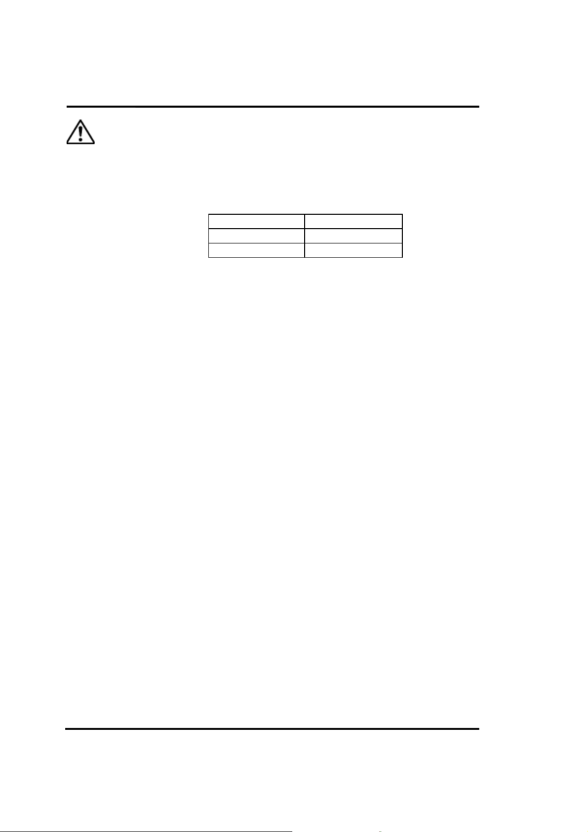
Cautions on Handling Laser Light
1. IEC
A semiconductor laser is used as the sensor's light source.
The laser is classified based on IEC standards (EN60825).
Wavelength 685nm
Maximum Output 1mW
Class 2
Cautions
1) Be careful not to look directly at the laser beam or at its reflection from a
mirror surface.
2) Mount the sensor at a height above or lower than eye level so the beam will
not shine directly into eyes during operation.
The safety distance (Nominal Optical Harm Distance: NOHD) is approximately 0.6m, but make sure the laser beam hits a diffusing reflector or an
absorbing body.
3) Laser beam emission can be stopped using the timing input supplied at the
input terminal (see TM1 and TM2 on page 3-5 and page 5-6). Or, select
"Open circuit" for the input operation of the timing input terminal (see page
5-34) to use the terminal for a remote interlock input.
4) The sensor head in this device is not equipped with a function that stops
laser radiation automatically when it is disassembled, so contact SUNX if it
breaks down.
There is danger of laser radiation if the head is disassembled for repair,
etc.
5) Do not use the device in operation other than that specified in this
Instruction Manual.
Caution – You may be exposed to hazardous laser radiation if the device is
controlled or adjusted in procedures not specified in this manual.
6) Read the contents of the warning label below carefully before use.
The warning label is affixed to the side of the sensor head. The English
warning label is packed with the sensor, so be sure to follow the instructions
printed on it during use.
2
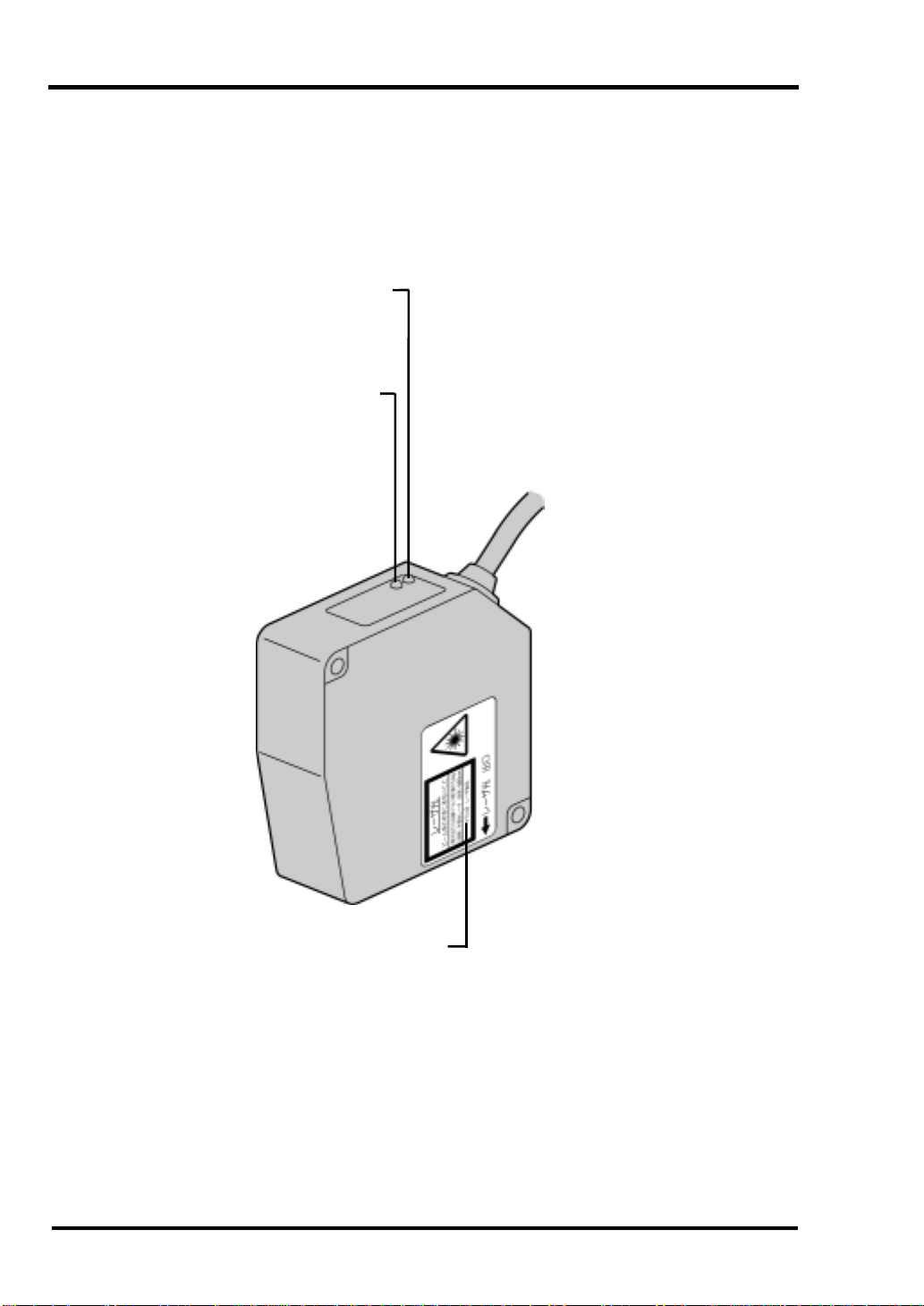
Page 8
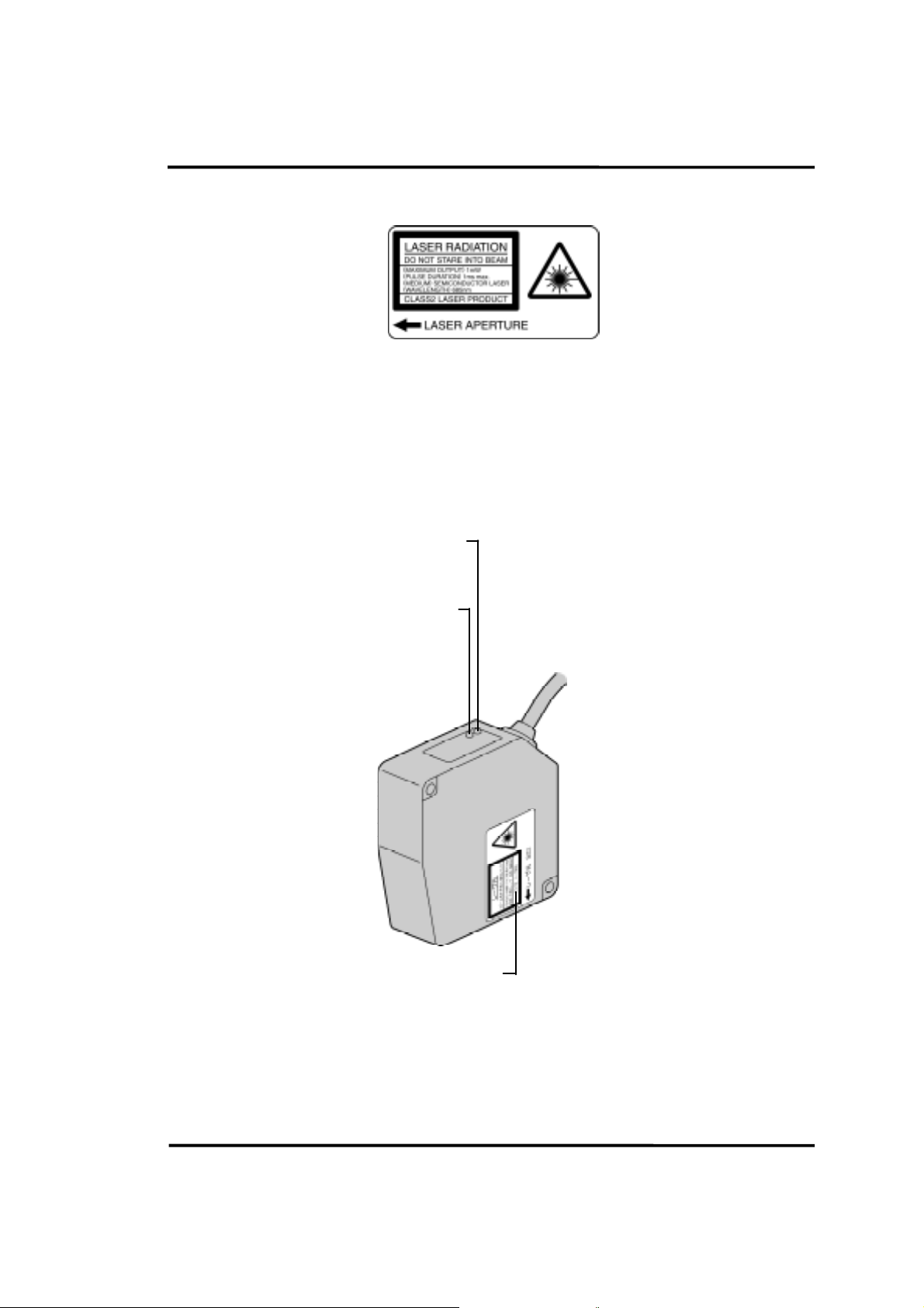
Laser Emission Indicator
Measurement Range Indicator
Warning Label
3
Page 9

2. FDA
Export to US
To export the laser product to the US installed on equipment, it is restricted by
the regulation of the USA Food and Drug Administration (FDA).
Use equipment compatible to the FDA.
The equipment below is compatible.
HL-C105F
HL-C105F-BK
HL-C108F
HL-C108F-BK
The FDA establishes the standard below to prevent problems to the user
previously due to laser product.
PART1040
(PERFORMANCE STANDARDS FOR LIGHT-EMITTING PRODUCTS)
– Execution standard for laser beam emitting product –
This standard classifies the laser product based on the level of laser danger
and stipulates preventive safety measures to be executed for each class. See
requirements on page 7.
The classification of equipment type is as follows:
Classification of HL-C10F, HL-C10F-BK (FDA)
Class II
4
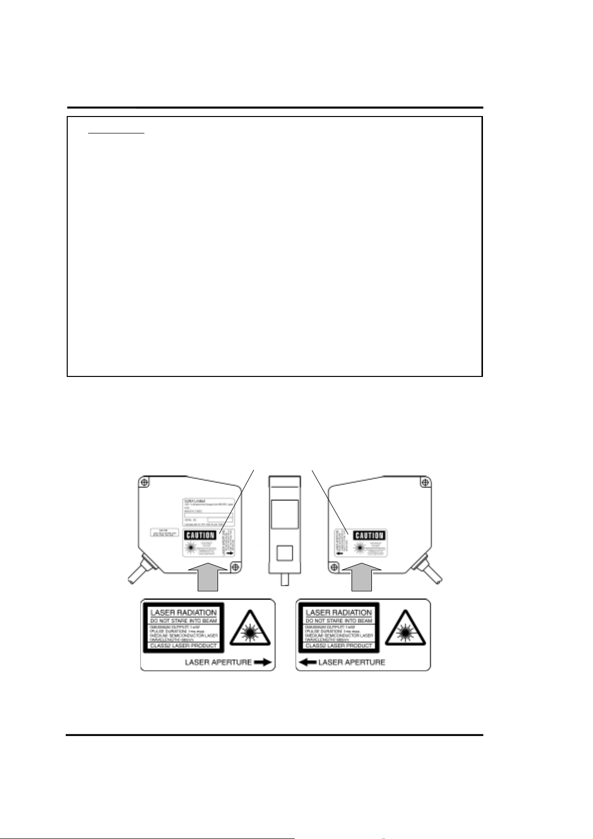
Page 10
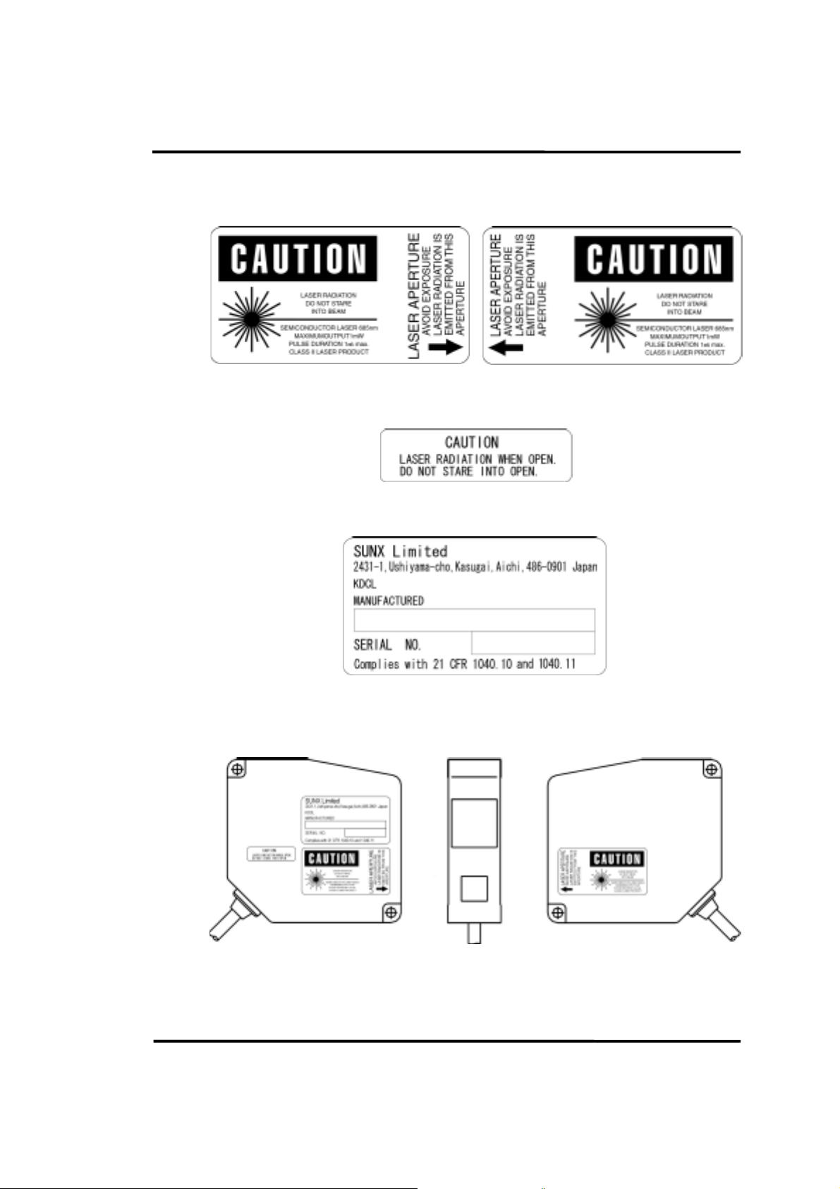
This equipment uses the following labels in accordance with
(1) Warning label
(2) Protective casing label
(3) Certificate/identification label
FDA standards:
<Label position>
5
Page 11
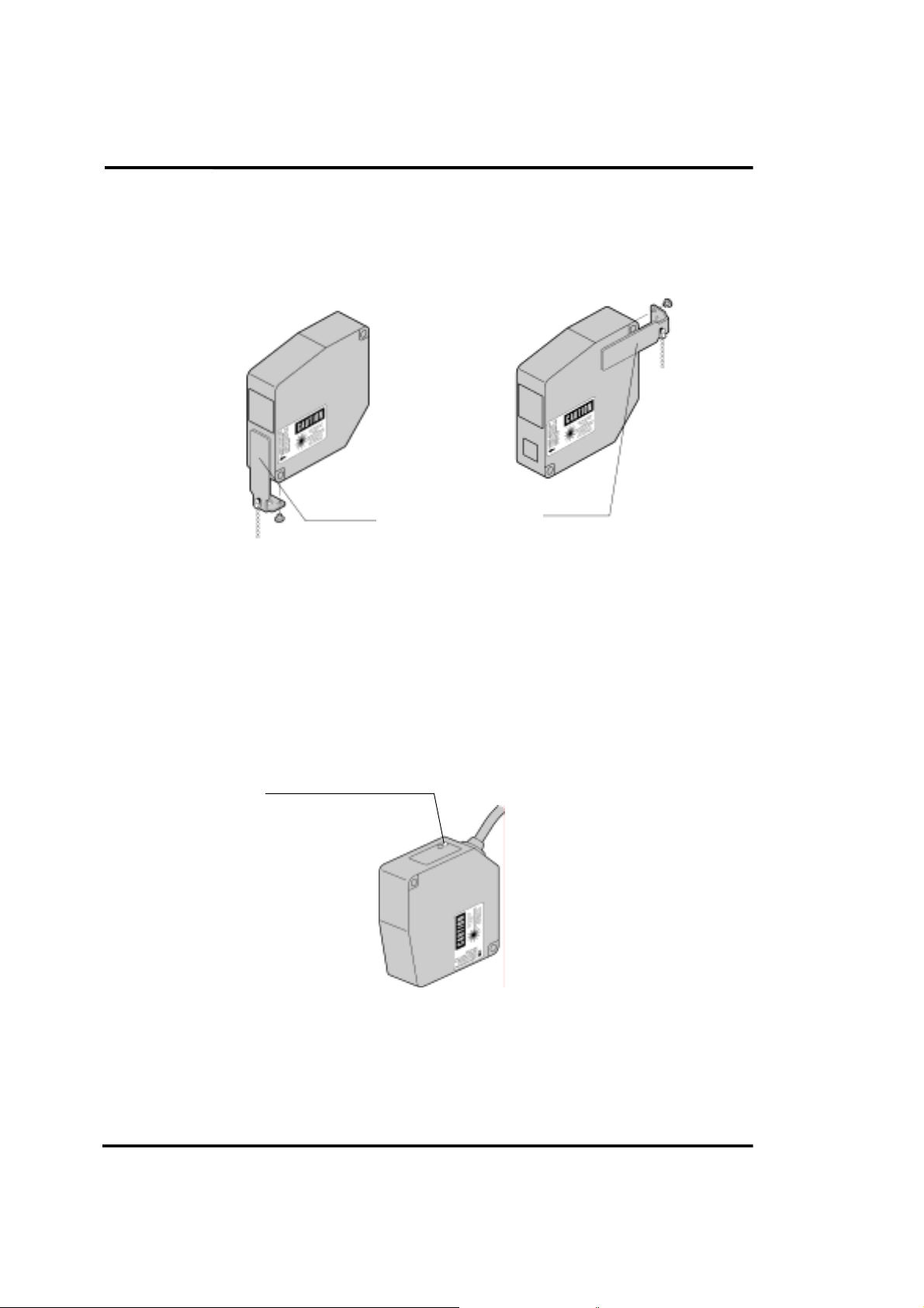
Beam attenuator
When the laser beam may enter eyes during work, work with the beam
attenuator installed.
Beam
attenuator
To attach the beam attenuator, fix
it with the attached screws in such
a manner as to cover the light
projection surface.
When the beam attenuator is not
used, fix it to either side surface of
sensor head, using the attached
screws.
Beam
attenuator
Laser emission indicator
While the laser is emitted, the LED (green) on the sensor head goes on.
It is also possible to recognize the LED through the laser protective glasses.
Laser emission indicator
6
Page 12
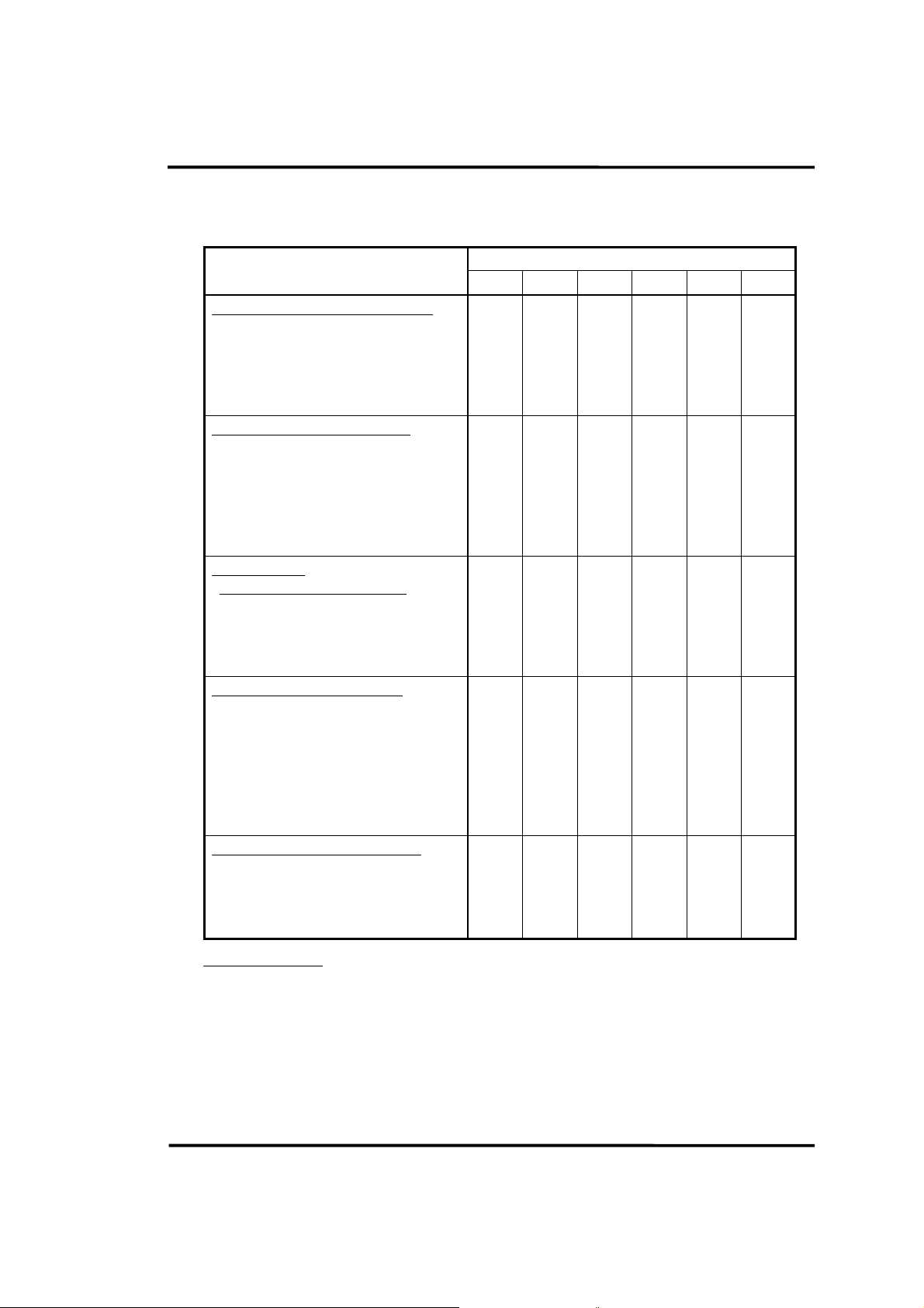
Tabulation of FDA Requirements for Laser Products
Requirements
Performance (all laser products)
Protective housing [1040.10(f)(1)]
Safety interlock [1040.10(f)(2)]
Location of controls [1040.10(f)(7)]
Viewing optics [1040.10(f)(8)]
Scanning safeguard [1040.10(f)(9)]
Performance (laser systems)
Remote control connector
[1040.10(f)(3)]
Key control [1040.10(f)(4)]
Emission indicator [1040.10(f)(5)]
Beam attenuator [1040.10(f)(6)]
Reset [1040.10(f)(10)]
Performance
(specific-purpose products)
Medical [1040.11(a)]
Surveying, leveling, alignment
[1040.11(b)]
Demonstration [1040.11(c)]
Labeling (all laser products)
Certification & identification
[1010.2, 3]
Protective housing
[1040.10(g)(6), (7)]
Aperture [1040.10(g)(4)]
Class warning
[1040.10(g)(1), (2), (3)]
Class
I IIa II IIIa IIIb IV
R
3,4
R
N/A
R
R
N/A
N/A
N/A
N/A
N/A
S
S
S
R
D
N/A
N/A
2
5
R
3,4
R
R
R
R
N/A
N/A
N/A
N/A
N/A
S
S
S
R
R
N/A
R
2
5
6
R
3,4
R
R
R
R
N/A
N/A
R
R
N/A
S
S
S
R
R
R
R
2
5
7
R
3,4
R
R
R
R
N/A
N/A
R
R
N/A
S
S
S
R
R
R
R
2
2
R
3,4
R
R
R
R
R
R
10
R
R
N/A
8
8
S
NP
11
S
R
5
9
5
R
R
12
R
R
R
R
R
R
R
R
R
R
R
S
NP
S
R
R
R
R
2
3,4
10
13
8
11
5
12
Information (all laser products)
User information [1040.10(h)(1)]
Product literature [1040.10(h)(2)(i)]
Service information
R
N/A
R
R
R
R
R
R
R
R
R
R
R
R
R
[1040.10(h)(2)(ii)]
Abbreviations:
R – Required
N/A – Not applicable
S – Requirements : Same as for other products of that Class. Also see
footnotes.
NP – Not permitted
D – Depends on level of interior radiation
7
R
R
R
Page 13
Footnotes:
1. Based on highest level accessible during operation.
2. Required wherever & whenever human access to laser radiation above
Class I limits is not needed for product to perform its function.
3. Required for protective housing opened during operation or maintenance, if
human access thus gained is not always necessary when housing is open.
4. Interlock requirements vary according to Class of internal radiation.
5. Wording depends on level & wavelength of laser radiation within protective
housing.
6. Warning statement label.
7. CAUTION logotype.
8. Requires means to measure level of laser radiation intended to irradiate the
body.
9. CAUTION if 2.5 mW cm
-2
or less, DANGER if greater than 2.5 mW cm-2.
10. Delay required between indication & emission.
11. Variance required for Class IIIb or IV demonstration laser products and light
shows.
12. DANGER logotype.
13. Required after August 20, 1986.
Export to countries overseas other than the US, and use of products in
countries overseas other than the US
When the product is exported to regions other than the US or used in regions
other than the US, change warning labels (HL-C10F, HL-C10F-BK)
compatible to the FDA, with attached labels (indicated in English) as shown
below.
FDA warning label
Attached warning label (English)
8
Page 14

Correct Handling
Note the following points when installing and using this product:
1. Warming Up Time
• Allow at least 30 minutes of warming up after turning on power to ensure
optimum conductance.
2. Use Environment
Ambient Temperature, Humidity, Luminance
• Use this product in the temperature specification range (sensor head: 0 to
+45qC, controller: 0 to +50qC, compact console: 0 to +40qC). If the sensor is to
be stored, the temperature range during storage should be –20 to +70qC.
• The service life of a semiconductor laser depends on the ambient temperature
during use. If the product is used near a heat source, take measures to lower
the ambient temperature of the sensor head as far as possible. Because the
sensor itself emits heat, mount the sensor on a device having good heat
radiation.
• Use the sensor in a range of 35 to 85% RH relative humidity. Avoid use in
places that may be exposed to sudden temperature fluctuations causing
condensation.
• Use the sensor where luminance at the light sensor from incandescent lamps is
3,000 lx or less.
Power Supply Voltage
• The power supply voltage should be within the rated voltage range of 21.6 to
26.4V DC during use.
Environment
• If the external surge voltage exceeds 500V [± (1.2 × 50) µs unipolar full wave
voltage], the internal circuit may be destroyed. If there is danger of external
surge voltages exceeding 500V, install a surge protector between the power
supply and input terminal.
• Water or oil, or fingerprints, etc., on the sensor's emitter or receiver surfaces
refracts light, and dust or dirt cuts light, so keep the sensor clean at all times.
When cleaning these parts, wipe them off using a soft lint-free cloth or lens
cleaning paper.
• Set the sensor head so stray light such as sunlight or light with the same
wavelength, etc., does not enter the light receiver. If high accuracy is required,
install a light shielding plate or the like at the sensor.
9
Page 15

• The sensor head is a waterproof device, but this does not mean that it can be
installed underwater or in places where rain falls. Due to their construction, the
controller and connectors are not dustproof, waterproof, or corrosion-resistant,
so do not use it in an environment where such features are required.
• Do not use this product in places where flammable or corrosive gases are
generated, where dust is excessive, where there is dripping water, where it is
exposed to direct sunlight or severe vibration or impact.
3. Noise Measures
• Do not run the sensor cable along (bundled in parallel with) other wiring, and
keep it at least 100mm from other wires. Run the cable so it is separate from
high voltage and power circuit lines. If running lines in parallel cannot be
avoided, shield the cable by running it through a grounded electrical conduit,
etc.
• For input signal lines and output signal lines, run them separately, not in parallel,
with power lines and power supply lines, keeping them at least 100mm apart. In
addition, keep all signal lines as short as possible when connecting them.
• Install this product as far away as possible from high-voltage lines, power lines,
high voltage device, wireless devices and machines which generate a large
starting and stopping surge.
• If a large amount of electrical noise is generated in the power supply, analog
output is affected. Use a noise filter or a noise dampened transformer.
• Use shielded cables for signal wires such as those for serial input and output
and I/O terminals to reduce electric noise, and connect the shielding wire to the
frame ground.
• It is easy for analog outputs to be influenced by noise, especially from external
sources, so use shielded wires, and keep wiring as short as possible.
• Use an exclusive class D ground based on the functional ground terminal, and
avoid grounding this device in common with other devices. If it is grounded in
common with other devices, the opposite effect may occur.
4. Insulation Resistance and Voltage Resistance
• Do not conduct insulation resistance and voltage resistance tests between the
power supply, input and output signals, and metal parts of the controller.
10
Page 16

5. Power Supply
• Select a power supply with a ripple of 0.5V or less (P-P) and a current capacity
of 2A or more.
• When a commercial switching regulator is used, always use it with the frame
ground (F.G.) terminal connected to ground to avoid the influence of high
frequency noise.
• When using a transformer in the power supply, use an insulated transformer. If
an auto transformer (single turn transformer) is used, this product or the power
supply may be damaged.
• Do not turn the controller's power on again within 10 seconds after turning
power off.
• Use an insulated power supply with a built-in protective circuit to protect against
abnormal voltages from the power line.
• If a power supply without an internal protective circuit is used, be sure to supply
power via a protective element such as a fuse.
6. Instantaneous Power Failures
• If the duration of an instantaneous power failure is 10ms or less, operation
continues.
• If the duration of an instantaneous power failure is 10 to 45ms, one of the
following occurs:
(1) Operation continues.
(2) Analog output changes temporarily and BRIGHT and DARK indicators blink,
then the sensor recovers automatically.
(3) The same status as when the power supply is turned on occurs.
• If an instantaneous power failure lasts more than 45ms, the same status as
when the power supply is turned on occurs.
7. Installation
Controller
• Install the controller unit based on "Heat Radiation Considerations" on page 22, assuring plenty of space around the unit. If it is installed in a manner that is
not based on instructions, it could cause malfunction due to the rise in
temperature, etc.
• If the controller is mounted on a control board, etc., internally where air circulation
is blocked, ambient temperature will rise due to heat generated by the controller,
so use forced cooling.
• If multiple units are installed in series, they can be installed against each other
only if they are installed vertically.
• Ventilation slits for heat radiation are provided in the controller. Provide adequate
space for radiating heat to dissipate, so as not to block the ventilation slits.
11
Page 17

Wire Connections and Connectors
• Connect all wiring securely based on the input and output circuit explanations
and according to markings. Ensure that wiring is correct.
• When connecting and disconnecting connectors and when making all connections,
make sure that controller power is turned off.
• When connecting and disconnecting connectors, take hold of the connector,
being careful not to exert undue force on cables.
• Be careful not to touch terminals or let foreign matter get in the connector when
disconnecting connectors.
• Be careful to keep from applying force to each of the cables near to connectors.
Do not bend cables near connectors because this breaks wires.
Cables
• Do not pull the cable at a force more than
29.4N when routing the cable after fixing the
20mm or more
sensor head and controller. Do not allow
30mm or a shorter bending radius in the cable
path. During use, do not bend the cable at a
place within 20mm of the sensor head's cable
R30 or more
inlet.
• If the sensor head is to be used in a situation
where it is moved during operation, install it
so the cable will not flex during movement. If
flexure is necessary, use an extension cable
that can be replaced.
• Use only 1 extension cable for connection between 1 sensor head and controller.
Do not connect more than 2 extension cables or equipment may be adversely
affected by noise.
12
Page 18

Warranty
Warranty
• The warranty period for this product is 1 year from the date of purchase or from
the date of delivery to the place specified by your company.
Extent of Warranty
• If this product should break down or if a defect becomes apparent which is the
responsibility of SUNX during the warranty period, SUNX will promptly provide
a replacement product or the necessary replacement parts, or will replace or
repair the defect parts free of charge at the place where the product was
purchased or at the place where delivery was made.
The provisions of this warranty do not cover any of the following cases to
breakdown or defect:
(1) The breakdown or defect was caused by specifications, standards, handling
methods, etc., instructed by your company.
(2) The breakdown or defect was caused by modifications in construction,
conductance, or specifications, etc., which SUNX was not involved in were
conducted after purchase or after delivery.
(3) The breakdown or defect occurred due to phenomena which it was
impossible to foresee in technologies which were applied after purchase or
during the warranty period.
(4) The product was used without heeding the conditions and environmental
restrictions included in the instruction manual.
(5) This product is incorporated into your company's equipment and that
equipment, with functions and construction, etc., which are generally
provided in the industry, suffered avoidable damage.
(6) The breakdown or defect was caused by natural disaster or other acts of
God.
The warranty is limited to purchased or delivered products only, and does not
cover any incidental damage resulting from breakdown of or defects in this
product.
The above contents presuppose that the product was purchased and used
within the borders of Japan.
Please contact our company's representative separately if you have requests
concerning purchase or use of this products in nations other than Japan, or
about specifications, warranty, service, etc.
13
Page 19

CHAPTER 1
NAMES AND FUNCTIONS OF PARTS
Page 20
CHAPTER 1 NAMES AND FUNCTIONS OF PARTS
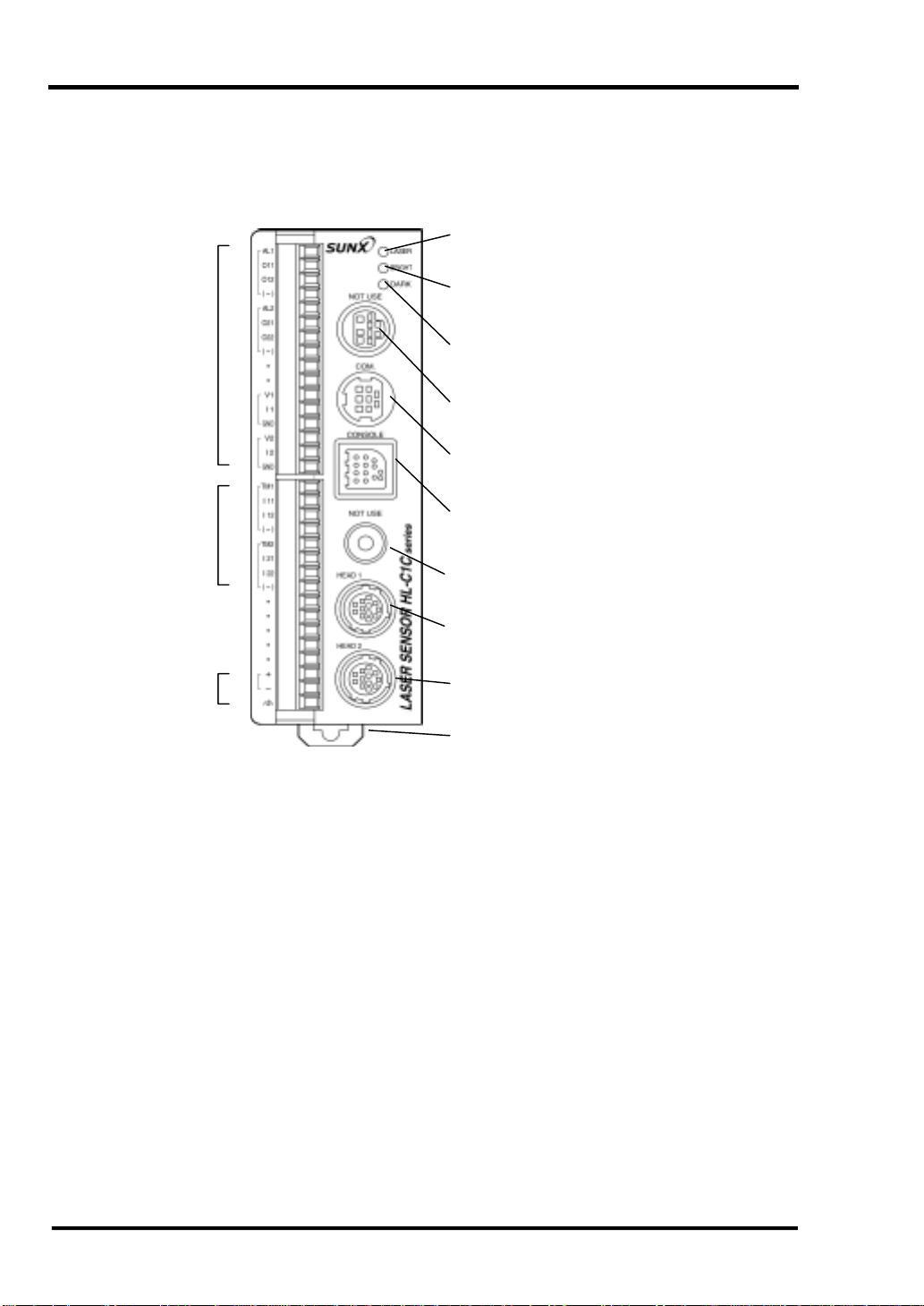
1-1 Controller
(1) Laser Emission Indicator (Green)
(2) BRIGHT Indicator (Red)
(3) DARK Indicator (Red)
(11) External Output
Terminals
(12) External Input
Terminals
(4) Not used.
(5) COM. Port
(6) Connector for Compact Console
(7) Not used.
(10)Power Supply
Terminals
(8) Sensor Head 1 Connector
(9) Sensor Head 2 Connector
(13) DIN Rail Mounting Hook
1-1
Page 21

CHAPTER 1 NAMES AND FUNCTIONS OF PARTS
(1) Laser Emission Indicator (Green)
Lights during laser emission from sensor head 1 or sensor head 2, or immediately before
laser emission.
(2) BRIGHT Indica tor (Red)
Lights when light emitted by sensor head 1 or sensor head 2 is excessive, preventing
measurement.
(3) DARK Indicator (Red)
Lights when light emitted by sensor head 1 or sensor head 2 is insufficient, preventing
measurement.
(4) Not used.
This port is for adjustment at the factory before shipping.
(5) COM. Port
Used for RS-232C communications with a personal computer.
(6) Connector for Compact Console
This enables measurement values to be displayed using the compact console and
connection of the compact console exclusive connection cable when setting each setting.
(7) Not used.
This port is for adjustment at the factory before shipping.
(8) Sensor Head 1 Connector
The controller operates the sensor head connected to this connector as sensor head 1.
(9) Sensor Head 2 Connector
The controller operates the sensor head connected to this connector as sensor head 2.
For a system with only 1 sensor head connected to the controller, connect to the sensor
head 1 connector (8).
(10) Power Supply Terminals
Supplies 24V DC.
(11) External Output Terminals
(12) External Input Terminals
(13) DIN Rail Mounting Hook
Can be mounted on a 35mm width DIN rail quickly.
1-2
Page 22
CHAPTER 1 NAMES AND FUNCTIONS OF PARTS
(
)
(
)
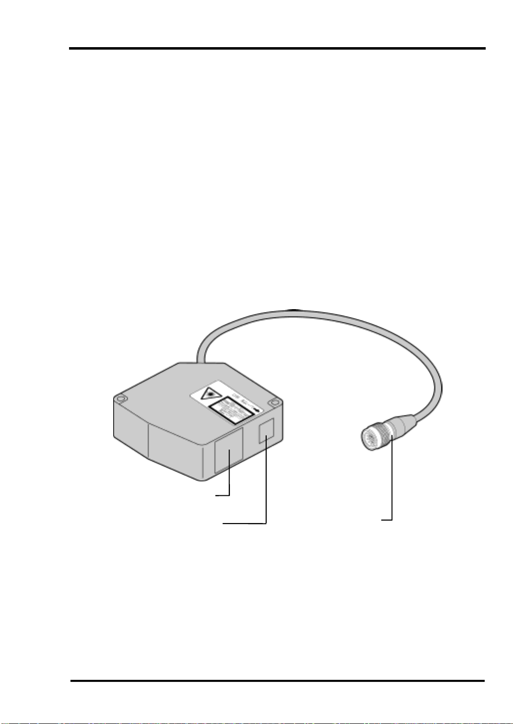
1-2 Sensor Head
(1) Laser Emission Indicator
Green
(2) Measurement Range Indicator
Yellow
(3) Warning Label
1-3
Page 23
CHAPTER 1 NAMES AND FUNCTIONS OF PARTS
(1) Laser Emission Indicator (Green)
Lights during laser emission or immediately before laser emission.
(2) Measurement Range Indicator (Yellow)
Blinks when within the measurement range and lights when near the center of the
measurement range.
(3) Warning Label
Shows the laser emission position. Note description contents.
(4) Light Receiver
Receives light reflected from the measured object.
(5) Light Emitter
Emits laser light.
(4) Light Receiver
(5) Light Emitter
Connector
1-4
Page 24
CHAPTER 1 NAMES AND FUNCTIONS OF PARTS
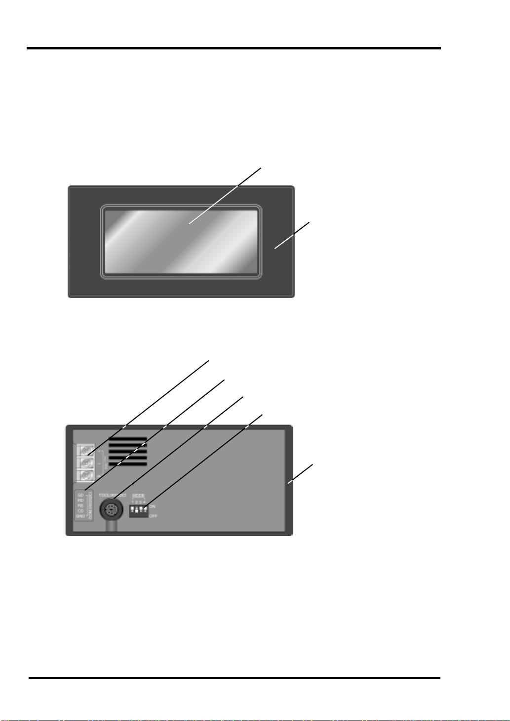
1-3 Compact Console
[Front]
(1) Liquid Crystal Panel (Touch Panel)
(2) Front Protective Sheet
[Rear]
(3) Power Supply Terminal
(4) COM. Port
(5) (TOOL Port)
(6) (Operating Mode Setting Switch)
(7) Waterproof Packing
1-5
Page 25
CHAPTER 1 NAMES AND FUNCTIONS OF PARTS
(1) Liquid Crystal Panel (Touch Panel)
Measuring data and setting values are displayed. The setting can be changed and data
input by touching the panel.
(2) Front Protective Sheet
A sheet is affixed to the liquid crystal panel when the sensor is shipped to protect it and
keep it clean.
(3) Power Supply T erminal
Supplies 24V DC for the operation power supply.
(4) COM. Port
This port is used for connecting the compact console to the controller using the exclusive
cable provided with the console.
(5) (TOOL Port)
The TOOL port is used to create screen data with the product connected to a personal
computer. Do not use the port for this equipment, equipment has already been incorporated
with dedicated screen data.
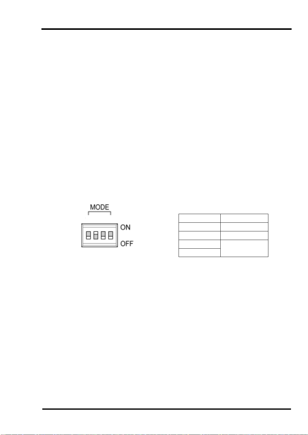
(6) (Operating Mode Setting Switch)
Use this product in the status below to protect exclusive screen data.
1234
(Settings when shipped from the factory)
(7) Waterproof Packing
This packing ensures that the panel is waterproofed from the front.
One packing is supplied when the product is shipped.
Switch No. Setting
1OFF
2ON
3
4
OFF
1-6
Page 26

CHAPTER 1 NAMES AND FUNCTIONS OF PARTS
MEMO
1-7
Page 27

CHAPTER 2
INSTALLATION
Page 28
CHAPTER 2 INSTALLATION
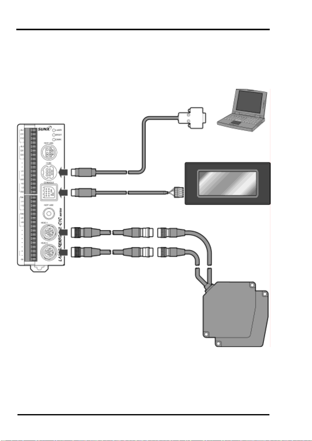
2-1 System Configuration
Controller
RS-232C Cable 3m
(Supplied with the intelligent
monitor HL-C1AiM)
Compact Console
Connection Cable 2m
(supplied with the compact console)
Extension Cable
2m, 5m, 10m, 20m, 30m
• For a system with only 1 sensor head connected to the
controller, connect to the sensor head 1 (HEAD 1)
connector.
Sensor Head
2-1
Page 29
CHAPTER 2 INSTALLATION
T
2-2 Installation Environment and Installation
Space
Avoid installation in the following places:
• Places where ambient temperature exceeds specifications (sensor head: 0 to +45°C,
controller: 0 to +50°C, compact console: 0 to +40°C).
• Relative humidity exceeds 35 to 85% relative humidity.
• Luminance at the light receiver exceeds 3,000 lx (incandescent lamp).
• Places subject to sudden temperature fluctuations that could cause condensation.
• Corrosive or flammable gases exist in the atmosphere.
• Iron chip, dust or salt is excessive.
• The atmosphere contains benzene, paint thinner, alcohol, or other organic solvents, or
where a danger exists of strong alkaline substances such as ammonia or caustic soda
adhering to the sensor.
• Vibration or impacts are severe.
• Places exposed to direct sunlight.
• Water, oil, chemicals, etc., could contaminate the product.
• Loads are applied to the sensor head.
Noise Considerations
• Mount this product as far as possible from high voltage lines, high voltage equipment,
power lines, power equipment, equipment that generates large start and stop surges,
and welders, inverter motors, and other equipment that generates electric noise.
• Mount this product as far as possible from equipment with a transmitter such as
amateur radio equipment.
• Do not let excessive static electric charges be applied to the panel surface since it
could destroy the LCD unit.
Heat Radiation Considerations
• Do not mount this product on a heater, transformer, or other device that radiates large
amounts of heat such as high capacity resistors.
• If the controller is mounted internally on a control board where air circulation is blocked,
ambient temperature will rise due to heat generated by the controller, so use forced
cooling.
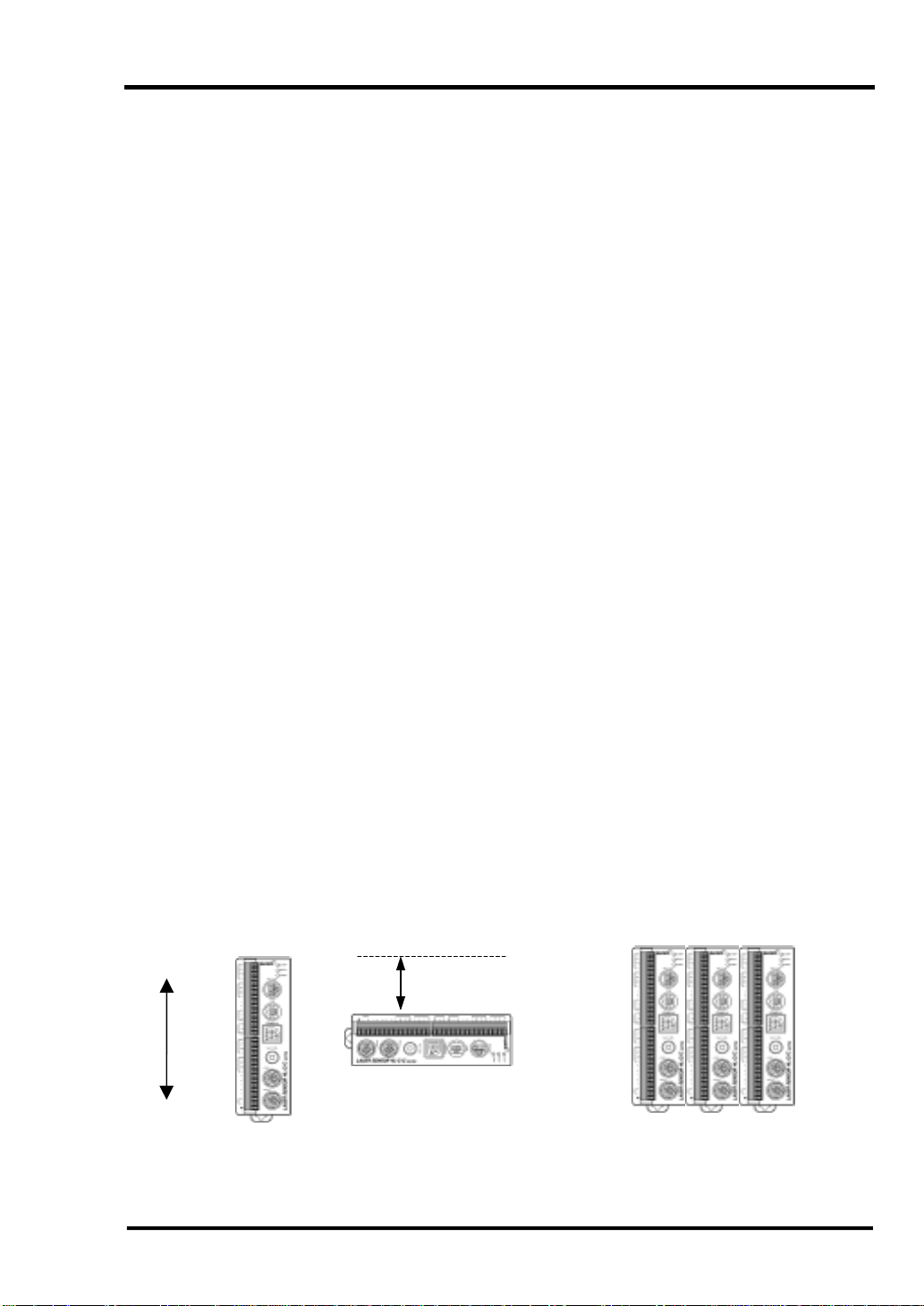
• Mount the controller with the following orientation to facilitate heat dissipation.
[Mounted vertically] [Mounted horizontally] [Multiple units mounted side by side]
op
Bottom
100mm or more
Mount the controller with the side
containing slits facing up.
Mount the controller in the orientation
shown in the figure above.
2-2
Page 30
CHAPTER 2 INSTALLATION
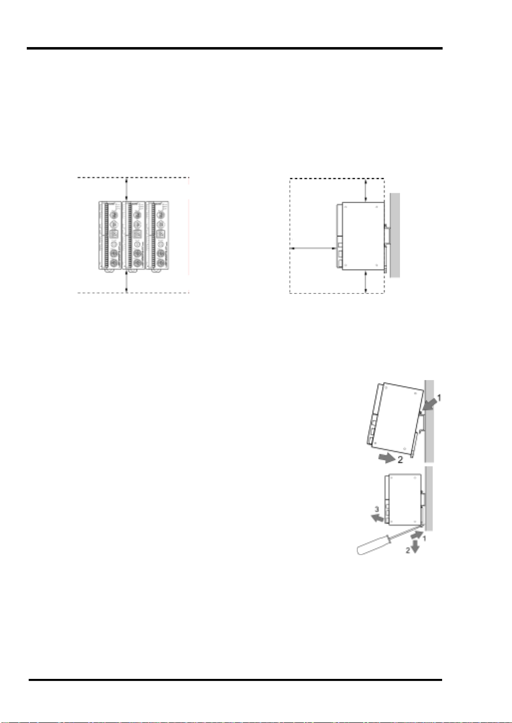
Installation Space
• Mount the controller so it is separated from surrounding ducts and other devices by
50mm or more to enable replacement, wiring, etc.
• If a panel door or other device is placed in front of the controller unit, separate it from
the controller by 100mm or more to avoid the influence of radiation noise or heat
generation.
• Ensure that there is an allowance of 100mm or more from the controller's front surface
to enable connection of sensors, wiring, etc.
50mm or more
50mm or more
50mm or more
100mm
or more
50mm or more
2-3 Mounting the Controller
The controller can be mounted by fastening it with screws or by using a DIN rail.
Mounting the Controller with a DIN Rail
The controller can be mounted or removed from a 35mm widt h DIN
rail (DIN EN 50022) in 1-touch operation.
[Mounting]
1.Hang the top on the DIN rail.
2.Push the bottom of the controller to fasten it on the rail.
[Removal]
1.Insert the blade of a flat-bladed screwdriver in the mounting lever.
2.Pull down the mounting lever.
3.Raise the controller and remove it from the rail.
Mounting the Controller with Screws
• While referencing the external dimensioned diagram on page 10-3,
use M3 screws to fasten the controller. Do not tighten screws
beyond 0.5N·m.
• To avoid breakage inside the controller, do not insert the screw tip
3.5mm or more from the side of the case.
• Use only the 4 screw holes included on the side of the case.
2-3
Page 31

CHAPTER 2 INSTALLATION
2-4 Mounting the Sensor Head
Mounting the Sensor Head
• Fasten the sensor securely with M5 screws, using the 2 holes in the corners of the
sensor head. Limit tightening torque to within 1.2N·m.
• Install the sensor head with the relative position of the object adjusted to the type
(50mm/85mm, diffused reflection/specular reflection) of equipment used, referencing
the installation dimension drawing.
• It is possible to connect the sensor head (50mm) and another sensor head (85mm) at
the same time. The initial setting within the controller will correspond to the type of
equipment connected. When equipment of a different type is connected at the same
time, however, the upper/lower limit setting, hysteresis setting, and analog setting for
addition/subtraction operation will correspond to the type of equipment connected to
the head-1 side connector. When necessary, change setting contents.
• If the power supply is turned on with the connection changed (change in equipment
type: 50mm, 85mm, change in connection from 1-sensor head to 2-senso r head o r vice
versa) from that when controller setting contents are saved, setting contents are
initialized. If the connection is incorrect, turn off the power supply to return the
connection to that when the controller setting was saved, then turn on the power supply
again, returning setting contents to that when the controller setting was saved. Note
that setting contents are not initialized when equipment is replaced with an equivalent
type or when the number of units is increased/decreased.
• Operate the sensor head within the temperature specification (sensor head: 0 to +45ºC,
controller: 0 to +50ºC, compact console: 0 to +40ºC).
• Service life of a semiconductor laser depends on ambient temperature during use. If
the sensor is used near a heat source, take cooling measures to lower ambient
temperature of the sensor head. The sensor generates heat, so mount the sensor head
on a unit having good heat radiation performance. *
* When installing 2 sensor heads in parallel at a 20mm or less interval, mount each
sensor head on an aluminum or iron plate having a 200cm
2
surface area.
2-4
Page 32

CHAPTER 2 INSTALLATION
• If the sensor is to be stored, temperature during storage should be -20 to +70ºC.
• Use the sensor at 35 to 85% relative humidity. Avoid use where sudden temperature
fluctuations could cause condensation.
• Use the sensor where luminance at the light sensor from incandescent lamps is 3,000lx
or less.
• Mount the sensor head so stray light such as sunlight or light with the sam e wavelength,
etc., does not enter the light receiver. Where accuracy is a factor, use with a shading
plate, etc.
• Do not mount the sensor head where flammable or corro sive gases are generated, dust
is excessive, water drips, exposure to direct sunlight is possible, or severe vibrations or
impacts occur.
Installation dimensions
z Measurement of diffused reflection
• 50mm type
• 85mm type
Beam
receiving
axis
Beam
receiving
axis
Beam
projecting
axis
Measurement
center
(Unit: mm)
Measurement
Range Indicator
(Yellow)
Laser Emission
Indicator
(Green)
(Unit: mm)
Measurement
Range Indicator
(Yellow)
Laser Emission
Indicator
(Green)
Beam projecting
axis
Measurement center
2-5
Page 33

CHAPTER 2 INSTALLATION
M
t
z Measurement of specular reflection
• 50mm type
Beam
receiving axis
Beam
projecting
axis
easuremen
center
• 85mm type
Specular reflection sensor head
setting reference surface
Specular reflection type sensor
head setting reference surface
(Unit: mm)
Measurement
Range Indicator
(Yellow)
Laser Emission
Indicator
(Green)
(Unit: mm)
Beam
receiving axis
Beam
projecting axis
Measurement
center
2-6
Measurement
Range Indicator
(Yellow)
Laser Emission
Indicator
(Green)
Page 34

CHAPTER 2 INSTALLATION
Sensor Head Mounting Direction
Mount the sensor head in the orientation shown below to ensure accurate measurement.
z Rotating objects
z Objects with level differences or grooves
z Objects with great changes in color
2-7
Page 35

CHAPTER 2 INSTALLATION
Mutual Interference
If more than 1 sensor head is mounted close together, no mutual interference will occur if
the neighboring sensor's laser spot is outside the shaded portion in the figure below.
Mount other sensor heads so laser spots do not enter the shaded area.
When using 2 sensor heads connected to 1 controller, it is possible to use the interference
prevention function. Refer to 5-2-12, "Interference Prevention".
• 50mm type
• 85mm type
2-8
(Unit: mm)
Page 36

CHAPTER 2 INSTALLATION
5
Beam Diameter
(Unit: mm)
• 50mm type
Measurement Range
Measurement Center Dist.
• 85mm type
Output Characteristics and Measurement Range
Indicator
z Measurement of diffused reflection
Lights
Measurement Range Indicator
•50mm type
•85mm type
Alarm Output
(N.C.)
Open
Closed
Off Blinks
Measurement Range
Measurement Center Dist.
–
–20
Blinks
Displacement
Output
+20
–5V
Off
+5
Distance (mm)
* Analog output is set to initial status
2-9
Page 37

CHAPTER 2 INSTALLATION
z Measurement of specular reflection
Measurement Range Indicator
Measurement Center Dist.
•50mm type
•85mm type
Off
Lights
Blinks Blinks
Measurement Range
Displacement
Output
Off
Distance (mm)
Alarm Output
(N.C.)
Open
Closed
*
* Analog output is set to initial status
2-10
Page 38

CHAPTER 2 INSTALLATION
2-5 Mounting the Compact Console
Mount the installation plate using the enclosed mounting fittings (4) and installation
screws (4).
(1) Insert the compact console unit in the mounting plate.
(2) Fit the mounting plate in the groove in the compact console unit, then tighten screws,
fastening the compact console to the mounting plate.
Use enclosed mounting fittings (4)
and installation screws (4).
Enlargement
• Tighten screws with a torque of 0.1 to 0.25N·m.
• Use a panel 1.0 to 6.0mm thick.
• If the mounting angle is 60 to 0° (horizontal), use
an operating voltage of 25V DC or less.
Mounting Angle
Clearances During Mounting
When mounting the compact console, if other parts are on the panel and wiring is required,
it is recommended that a clearance of 30 to 50mm be allowed around the compact console
to prevent damage to cables, improve workability, etc. Do not cover slits in the console unit.
Wiring the Connection Cable Terminal (Supplied)
• Connection cable terminal wiring is sho wn at rig ht.
• Before connection to the controller, turn off both
the compact console and controller.
• To prevent disconnection due to vibration, fix the
connecting cable near the compact console within
20cm of the COM. port.
Yellow
Red
White
2-11
Page 39

CHAPTER 2 INSTALLATION
Wiring the Power Supply
• Connect power supply wiring securely to the terminal on
the back of the main unit.
• Use twisted wires for power supply lines to minimize the
effect of noise.
• Use an insulated power supply with a built-in protection
circuit for the power supply to protect against abnormal
voltage from the power line.
• An uninsulated type is used in the regulator internally in the compact console.
• If a power supply is used that does not have a built-in protection circuit, connect the
power supply to the compact console via a fuse or other protective element.
• The power supply voltage should be within the rated voltage of 21.6 to 26.4V DC
during use.
• Use M3 screws to fasten the compact console. It is recommended that compression
terminals be used on ends of wires.
U-shape terminal
z
Round terminal
z
+24V
0V
6.0mm
or less
Maker Shape Model Applicable Wire Tightening Torque
Round 1.25-MS3
JST Mfg. Co., Ltd.
U-shape 1.25-B3A
Round 2-MS3
U-shape 2-N3A
6.0mm
or less
0.25 to 1.65mm
1.04 to 2.63mm
2
2
0.5 to 0.6N·m
• Tighten screws on the terminal block with a torque of 0.5 to 0.6N·m. Force exceeding
this may damage the device.
• If compression terminals are not used, use wire 0.5 to 1.25mm2 in diameter.
• To comply with the European EMC Directive, install a ferrite core (Seiwa Electric Mfg.
Co., Ltd. E04RC281613 or equivalent) on wires to the terminal block as shown below.
Ferrite Core
• Separate wiring to the compact console, PLC,
and power equipment.
Breaker
Power Equipment
2-12
Compact
Console
Insulated DC Power Supply
Page 40

CHAPTER 2 INSTALLATION
MEMO
2-13
Page 41

CHAPTER 3
INPUT AND OUTPUT TERMINAL
BLOCKS
Page 42

CHAPTER 3 INPUT AND OUTPUT TERMINAL BLOCKS
3-1 Wiring Terminal Blocks
Output Terminal Block
Input / Power Supply
Terminal Block
Terminal Blocks
The terminal block can be removable from the controller and tightened with screws. Use
the following tools and cables:
Enclosed Terminal Block Socket
(Equivalent)
Tightening Tools
(Tip width 0.4×2.5)
Applicable Wire (twisted wire)
Maker Model Product No. Tightening Torque
Phoenix Contact
(Co., Ltd.)
Phoenix Contact (Co., Ltd.) MC1,5/16-ST-3,5 (Color: Green)
Maker Model
SZS 0,4×2,5 1205037 0.22 to 0.25N·m
Size Conductor Cross-Section
AWG#24 to 16 0.3 to 1.25mm
2
3-1
Page 43

Wiring
CHAPTER 3 INPUT AND OUTPUT TERMINAL BLOCKS
1. Strip insulation from
the end of the wire.
2. Insert the wire in the
terminal block until it
contacts the back, then
secure it by tightening
the screw.
3. If more than 1 wire is
inserted into the same
terminal, twist wires
before inserting them.
Use the device as directed.
• Turn power supply off before wiring and remove or install the terminal block.
• Do not use wires tinned with solder. They may break when subjected to vibration.
• Wiring to the terminal block must not exceed 30m.
3-2
Page 44

CHAPTER 3 INPUT AND OUTPUT TERMINAL BLOCKS
3-2 Output Terminals
Terminal Layout
NPN output
Symbol Meaning
AL1 Alarm Output (Sensor Head 1)
O11 Judgment Output 1 (Sensor Head 1)
O12 Judgment Output 2 (Sensor Head 1)
(-) External Insulated GND
AL2 Alarm Output (Sensor Head 2)
O21 Judgment Output 1 (Sensor Head 2)
O22 Judgment Output 2 (Sensor Head 2)
(-) External Insulated GND
• Not used.
• Not used.
V1 Analog Voltage Output (Sensor Head 1)
I1 Analog Current Output (Sensor Head 1)
GND Analog Output Ground
V2 Analog Voltage Output (Sensor Head 2)
I2 Analog Current Output (Sensor Head 2)
GND Analog Output Ground
Photo-MOS output
Symbol Meaning
AL1 Alarm Output (Sensor Head 1)
O11 Judgment Output 1 (Sensor Head 1)
O12 Judgment Output 2 (Sensor Head 1)
COM Output Common
AL2 Alarm Output (Sensor Head 2)
O21 Judgment Output 1 (Sensor Head 2)
O22 Judgment Output 2 (Sensor Head 2)
COM Output Common
• Not used.
• Not used.
V1 Analog Voltage Output (Sensor Head 1)
I1 Analog Current Output (Sensor Head 1)
GND Analog Output Ground
V2 Analog Voltage Output (Sensor Head 2)
I2 Analog Current Output (Sensor Head 2)
GND Analog Output Ground
The COM (output common) terminals of
sensor head 1 and sensor head 2 are
connected internally.
Terminals marked with "•" are not used. Some are connected to internal circuitry, and
cannot be used as relay terminals in wiring, etc.
3-3
Page 45

Output Circuit
t
z Alarm Output, Judgment Output
CHAPTER 3 INPUT AND OUTPUT TERMINAL BLOCKS
NPN output
Photo-MOS output
Connection example 1 (NPN)
Load
50mA max.
COM.
Laser Sensor
z Analog Output Circuit
-10.9 to +10.9 V
Vx
0 to 29.5mA
Ix
Load
30V DC max.
Laser Sensor
Connection example 2 (PNP)
50mA max.
Load
COM.
Laser Sensor
Limit the spike voltage due to inductive load or circuit
wiring length to 350V AC or less at the output terminal.
Notes: 1) Do not short-circuit analog outpu
terminals or apply voltage to them.
2) Use shielded wires for analog
outputs.
Analog Input Device
ࠩࡦࠨ
Laser Sensor
• An alarm is output when the beam received is excessive or insufficient. The beam
received is determined each measurement cycle. When measuring a substance whose
beam received greatly fluctuates due to limited reflection beam, alarm output may
become unstable.
• Do not use output during start-up by turning on the power supply. Doing so may
change judgment output and alarm output during the period.
• Do not use analog output for several seconds right after turning on the power supply,
because analog output within ±5V (20mA or less) is sent during the period.
• Secure time of about 10 to 25 seconds, depending on the sampling period saved for
several seconds after turning on the power supply until the operation condition is
ensured (completion of start-up) (when the moving average count is turned off and
interference prevention function is turned off). This start-up time is increased by setting
the moving average count or by turning on the interference prevention function. It is
increased 1.2 to 2.4 times when the maximum moving average count is 32,768 times,
and to 1.4 to 3.3 times when the interference prevention function is turned on.
3-4
Page 46

CHAPTER 3 INPUT AND OUTPUT TERMINAL BLOCKS
3-3 Input Terminals
NPN output
Symbol Meaning
TM1 Timing Input (Sensor Head 1)
I11 Zero Set ON Input (Sensor Head 1)
Zero Set OFF Input (Sensor Head 1)
I12
(-) External Insulated GND
TM2 Timing Input (Sensor Head 2)
I21 Zero Set ON Input (Sensor Head 2)
I22 Zero Set OFF Input (Sensor Head 2)
(-) External Insulated GND
• Not Used.
Photo-MOS output
• Not Used.
• Not Used.
• Not Used.
• Not Used.
24V DC Input for Power Supply
+
– Power Supply Ground
Function Ground
Terminals marked with "•" are not used.
Some are connected to internal circuitry,
and cannot be used as relay terminals
Symbol Meaning
TM1 Timing Input (Sensor Head 1)
I11 Zero Set ON Input (Sensor Head 1)
I12 Zero Set OFF Input (Sensor Head 1)
COM Input Common
TM2 Timing Input (Sensor Head 2)
I21 Zero Set ON Input (Sensor Head 2)
I22 Zero Set OFF Input (Sensor Head 2)
COM Input Common
• Not Used.
• Not Used.
• Not Used.
• Not Used.
• Not Used.
24V DC Input for Power Supply
+
– Power Supply Ground
Function Ground
3-5
The COM (input common) terminals of sensor
head 1 and sensor head 2 are connected
internally.
Page 47

in wiring, etc.
CHAPTER 3 INPUT AND OUTPUT TERMINAL BLOCKS
3-6
Page 48

CHAPTER 3 INPUT AND OUTPUT TERMINAL BLOCKS
Input Circuit
NPN output
Internal
Circuit
Photoelectric Sensor, etc.
Laser Sensor
Operating input voltage: 12 to 24V DC
Photo-MOS output
Maximum input voltage : 30V DC
Connection example 2 (PNP)Connection example 1 (NPN)
Internal
Circuit
Photoelectric
Sensor, etc.
Laser Sensor
Internal
Circuit
Photoelectric
Sensor, etc.
Laser Sensor
• A continuous 2ms or more input is accepted at the Zero Set ON and Zero Set OFF
input terminals (1-shot input).
• When Zero Set ON is input from the input terminal, it is possible to input it again under
Zero Set status, for which Zero Set operation is executed for each input.
• Do not add the Zero Set ON and Zero Set OFF inputs simultaneously. Allow 2ms or
more interval between the inputs.
• Add Zero Set ON input only when the sensor head is within the measurement range.
• If lump input mode is selected (see page 5-35), add timing input, Zero Set ON input,
and Zero Set OFF input at either the sensor head 1 or sensor head 2 input terminal.
3-7
Page 49

CHAPTER 3 INPUT AND OUTPUT TERMINAL BLOCKS
3-4 Wiring Power Supply
Terminal Layout
• Use the plus (+) terminal and minus (-) terminals on the input terminal block to wire the
power supply, supplying 24V DC.
• Use twisted wires for the power supply to minimize the effect of noise.
Rated Voltage
Permissible Voltage
Fluctuation Range
Current Consumption
Inrush Current
24V DC
21.6 to 26.4V DC
1 Sensor Head: 0.43A approx.
2 Sensor Heads: 0.55A approx.
8A or less
24V DC
Use an Insulated Power Supply with an Internal
Protective Circuit of Sufficient Capacity.
• Large current exceeding the rated current flows temporarily when power is turned on.
Use an insulated power supply with an internal protective circuit of sufficient capacity
(margin of 2A or more current capacity) to protect the circuit against irregular voltage in
the power line, and check power-on operation.
• An uninsulated type is used in the controller's regulator.
• If a power supply without an internal protective circuit is used, supply power to the
controller via a protective element such as a fuse.
Switch the Power Supply On and Off at the Primary
Side.
• Switch the power supply on and off at the primary side (100V AC). If it is switched on
and off at the secondary side (24V DC), the controller's fuse may burn out.
Primary Side Secondary Side Primary Side Secondary Side
Power
Supply
Laser
Sensor
Power
Supply
Laser
Sensor
To Improve Noise Resistance
• Wire the controller, input device, and power device to run on separate systems.
• If noise from input and output circuits is a concern, it is recommended that power be
supplied separately for the controller and input and output power supplies.
3-8
Page 50

CHAPTER 3 INPUT AND OUTPUT TERMINAL BLOCKS
Consider the Power Supply Sequence.
• Consider the power supply sequence in which the controller's power supply is turned
off before input and output power supplies.
• If input and output power supplies are turned off before the controller power supply, the
controller will detect a change in input signal level and may malfunction.
• Do not turn the controller's power supply on again within 10 seconds after it is turned
off.
• It takes about 10 to 25 seconds ("Average number of samples" OFF and "Interference
prevention function" OFF) depending on the sampling period after power is supplied
until the controller is ready for operation (after completion of start-up). Do not use
output in the interval because output (judgment, alarm, and analog output) vary during
start-up.
Instantaneous Power Failures
• If an instantaneous power failure lasts 10ms or less, operation continues.
• If an instantaneous power failure lasts 10 to 45ms, one of the following occurs:
(1) Operation continues.
(2) Analog output varies temporarily and BRIGHT and DARK indicators blink, then
the sensor recovers automatically.
(3) The state changes to reset.
• If an instantaneous power failure lasts more than 45ms, the state changes to reset.
Use This Product Correctly.
• When wiring the power supply, turn the power supply off.
3-5 Grounding
Grounding When Effects of Noise are Great
• Under normal use, this product has sufficient noise resistance, but in an environment
with particularly high noise levels, ground it securely.
Use an Exclusive Ground.
•Use 2mm2or more wires and establish a class D ground with a ground resistance of
100: or less.
• Make the grounding point as close to the controller as possible, keeping the ground
wire distance short.
• If the laser sensor is grounded in common with another device, a reverse effect may
occur, so use an exclusive ground.
Laser
Sensor
Inverter or
other device
Laser
Sensor
Inverter or
other device
• The connector housing for the sensor head case and sensor cable is connected
electrically to the function ground of the controller terminal block via the sensor cable.
3-9
Page 51

CHAPTER 3 INPUT AND OUTPUT TERMINAL BLOCKS
MEMO
3-10
Page 52

CHAPTER 4
MEASUREMENT
Page 53

CHAPTER 4 MEASUREMENT
4-1 Basic Compact Console Operation
Screen Overview
MENU Screen
Screen Contents
MENU Main menu screen. All screens can be accessed via this screen.
Measurement
Measurement
Settings
Sensor
Adjustment
Data Processing
Input/Output
System
Displays measurement values. Used to switch to hold mode, zero
set, timing input, and other settings can be made.
Used to set the sampling period, sensor head operation, measurement
mode, and calculation formula.
Sets the correction value (span, shift) in measurement.
Sets the average number of samples, high pass filters, and low pass
filter.
Used to select the input or output function and set upper and lower
limit values, etc.
Saves or initializes setting contents, locks screens, sets the
communication specification, displays th e screen v e r s i o n , e t c .
Shifting Screen Levels
Touching item keys on the MENU screen changes the screen to respective operating
screens. Operating screens are arranged in a hierarchy. Move to the screen for the
desired function, then set necessary settings. Shifting among screen levels is explained
below.
: Shift down 1 level
: Shift up 1 level
: Advance to another item on the
same level
: Return to the previous item on the
same level.
4-1
Page 54

CHAPTER 4 MEASUREMENT
Selecting from items
This section explains how to select items having choices such as the sampling period
and average number of samples.
z Sampling period selected on measurement setting screen
The value in the frame is the current setting value.
The example shows that 1,000µs is selected.
Touching the number causes the setting value to change.
Setting values are changed in the following sequence:
Setting Value
100 144 200
Inputting a Value
This section explains value input for upper and lower limit
or offset, etc. A keyboard is displayed for items that can
be input.
1. Touch the frame above the setting value to change
the mode to the number input mode and causes the
cursor to blink.
2. Input the number from the keyboard.
3. Touch the decimal point on the keyboard to input
decimal fractions.
4. Touch the enter key to make the setting.
255 332 498 1000
Setting Value
Decimal Point
1
2
Caution
• Before connecting the compact console and controller, turn off both units.
• When the controller is connected to the compact console, the controller stops measuring
twice every 40ms approx. to ensure communication with the compact console.
Enter
3
4
4-2
Page 55

CHAPTER 4 MEASUREMENT
Screen Flow
Measurement
Sensor
Adjustment
System
Input/Output
1
2
3
Data Processing
Measurement
Setting
4
5
4-3
Page 56

CHAPTER 4 MEASUREMENT
1
2
3
4
5
4-4
Page 57

CHAPTER 4 MEASUREMENT
4-2 Measuring Height
This section explains measurement of differences in height of a measured object for a
reference surface. Basic operation is explained measuring the surface of a plate used as an
example.
Measurement Waveform
Procedure
1. Check all connections.
Confirm that the controller, sensor head, and compact console are connected.
2. Turn on power.
When the controller and sensor head have completed automatic start-up, the laser
emission indicator (green) lights and the laser radiates. If the measurement object is within
the measurement range, a measurement value is displayed on the compact console.
3. Adjust the position of the sensor head.
Set the orientation of the measurement object
and the sensor head referencing "Mounting
the Sensor Head" on page 2-4.
While observing the measurement range
indicator (yellow) of the sensor head or
measurement display on the compact
console, adjust the mounting position of the
sensor head so the approximate measurement center is in the center of the measurement object variation range.
The measurement range indicator (yellow)
blinks when the distance from the measurement object is within the measurement range
and remains lit when near the measurement
center distance.
Laser Emission
Indicator
Measurement
Range Indicator
Measurement
center distance
4-5
Page 58

CHAPTER 4 MEASUREMENT
4. Make a Zero Setting
Touch the button on the compact
console's measurement display
screen and switch to the subscreen 1
level down.
Touch
The display value and analog output
become "0", and the change in height
is then measured. See page 5-5 for
details on zero setting.
to make a zero setting.
Measurement Display Subscreen
MENU Screen
5. Measure the surface of the measurement object.
Move the measurement object or the sensor head
horizontally and measure the measurement item's surface.
Measurement Display Screen
z Supplementary Explanation
• If deviation in measurement occurs due to the status of the measurement object's
surface, see Calibration on page 5-36.
• If the sampling period (page 5-8), average number of samples (page 5-20), and digital
filter (pages 5-21, 22) are changed to correspond to the measurement object's speed
of movement, displacement, and displacement, more stable measurement can be
obtained.
• When the setting is changed, save the changed setting (page 5-41) before turning off
the power supply.
4-6
Page 59

CHAPTER 4 MEASUREMENT
M
4-3 Measuring Thickness
This section explains measurement of changes in thickness of the measurement object for
the reference thickness. The example shows basic operation for measuring the thickness of
a plate using 2 sensor heads.
Measurement Waveform
Procedure
1. Check all connections.
Confirm that the controller, sensor heads, and
compact console are connected.
2. Turn on power.
When the controller and sensor heads have
completed automatic start-up, the laser emission
indicators (green) lights and laser radiates light. If
the measurement object is within the measurement range, a measurement value is displayed on
the compact console.
3. Adjust the position of the sensor heads.
• Set the orientation of the measurement object
and the sensor heads referencing "Mounting the
Sensor Head" on page 2-4.
• While observing the measurement range indicator
(yellow) of the sensor head or measurement
display on the compact console, adjust the
mounting position of the sensor head so the
approximate measurement center is in the center
of the measurement object's variation range.
• The measurement range indicator (yellow) blinks
when the distance to the object is in the measurement range, and it lights roughly at the measurement center distance.
• Change between sensor head 1 (H1) and sensor
head 2 (H2) display on measurement display
screen of the compact console.
• When "add/subtract" is selected for the head
operation, change to "independent" referencing
page 5-10.
Measurement
Range Indicator
Laser Emission
Indicator
Measurement
center distance
easurement
center distance
4-7
Page 60

CHAPTER 4 MEASUREMENT
4. Set the head operation to calculations.
After returning to the MENU screen by pressing ,
touch
setting screen. Touch
and display the measurement
and display the
measurement condition screen. Touch the 'Head
Operation' key , and display
.
5. Set the Add/subtract Calculation formula.
Advance 2 screens from the measurement setting
screen (touch the
Add/subtract Calculation Screen. Touch the Calculation
Formula key and display
key 2 times), then display the
.
MENU Screen
Measurement Setting Screen
Measurement Condition Screen
6. Display the actual thickness.
On the subscreen the next level below the
"Add/Subtract Calculation" screen (touch the
key), input the offset value L using a value enabling
the actual measurement value to be displayed on the
measurement value display (see page 5-12).
The L input range is ±999.999mm.
After the setting is fixed, touch the
return to the MENU screen.
button and
Add/Subtract Calculation Screen
Offset Screen
4-8
Page 61

CHAPTER 4 MEASUREMENT
7. Measure the thickness of the measurement object.
Move the measurement object or sensor
heads horizontally and measure the thickness
of the measurement object.
When measuring the difference in thickness
from the reference work piece, touch the
key on the measurement display screen in
step 6, move to the subscreen 1 level below,
then touch and make a zero setting.
z Supplementary Explanation
• When deviation occurs in measurement value, based on the surface status of the
object, execute calibration, referencing page 5-36.
• Changing the sampling cycle (page 5-8), moving average count (page 5-20), and
digital filter (pages 5-21, 22), based on the speed of movement, displacement ratio ,
and displacement contents of object substance ensure furthermore stabilized
measurement.
• When the setting is changed, save changed setting (page 5-41) before turning off
the power supply.
Measurement Display Screen
4-9
Page 62

CHAPTER 5
FUNCTION ITEMS
Page 63

CHAPTER 5 FUNCTION ITEMS
g
j
y
p
5-1 Functions
Function Content Page
Measurement Display
Hold Mode
Measurement
Measurement
Settings
Data Processing
Input/output
Sensor Adjustment
System
Zero Set Sets measurement and analog output forcibly to zero. 5-5
Timing
Display Hold
Sampling Period
Sensor Head Operation
Calculation Formula
Emission Adjustment
Measurement Mode
Specular Reflection Mode
Interference Prevention
Laser Emission Delay
Average Number of Samples
Low Pass Filter
High Pass Filter
Simplified optical filter
Upper/Lower Limit Setting
Hysteresis Setting Sets hysteresis of upper and lower limit values. 5-25
Judgment Output Selection
Output Mode Uses judgment output as light alarm output. 5-28
Analog Output Setting Sets analog output corresponding to measure- ment. 5-29
Analog Output During Alarm
Analog Alarm Delay Ignores instantaneous analog alarm output. 5-32
Input Selection
Calibration Sets span and shift for calibration. 5-36
Light Received Displays light received. 5-40
Save Saves each setting in memory. 5-41
Initialization Returns to factory settings. 5-42
Lock
(Touch Key Lock)
Communication Specification Sets the controller communication specification. 5-45
Version Displays controller and compact console versions. 5-46
Monitors/displays measurements and alarm and
judgment output. Changes hold mode. Allows zero
setting, timing, and display hold input.
Chan
es hold mode between NORM. / P-P / PEAK
and VALLEY.
Holds judgment output, measurement, and analog output
to avoid unnecessary output changes or laser radiation.
Holds measurement displayed on the compact
console only.
Changes the sampling period to a little longer period,
to assure the stabilized measurement of workpieces
with low reflected light.
Changes between independent measurement and
add/subtract measurement with 2 heads.
Sets calculation formula selection, offset, and
coefficient for each sensor head.
Measures only the measurement point at high speed with
emission fixed.
Changes the diffused reflection mode/specular
reflection mode based on the sensor head connected.
Selects the measurement ob
reflection.
Prevents erroneous measurement within the mutual
interference area.
Dela
s laser emission for safety when the power
supply is turned on and when timing is turned off.
Sets the moving average number of samples to a large
number, to assure the stabilized measure- ment value.
Changes the cutoff frequency of the low pass filter to
avoid the influence of steep changes.
Changes the cutoff frequency of the high pass filter to
avoid the influence of gentle changes.
Reduces the influence due to turbulence of the reflected
light on the ground metal surface.
Sets the upper and lower limit values of judg- ment
output.
Selects a judgment output operation pattern. Switches
to test output mode.
Changes between analog output hold and fixed outof-range output issued at an alarm.
Reverses the in
emission during timing input continues. Switches to
independent/lump input.
Prohibits setting of or changes to the compact console
and prevents incorrect settings through inadvertent
operations.
ut operation of timing input. Laser
ect for specular
5-2
5-3
5-6
5-7
5-8
5-10
5-11
5-13
5-14
5-16
5-18
5-19
5-20
5-21
5-22
5-23
5-24
5-27
5-31
5-34
5-44
5-1
Page 64

CHAPTER 5 FUNCTION ITEMS
5-2 Explanation of Functions
5-2-1 Measurement Display
This function displays the measurement value, and is also used to monitor/display alarm
and judgment output, to change hold mode, and to allow zero setting, timing, and display
hold input.
1. Display the measurement display screen.
When
measurement display screen is displayed,
measurement is displayed based on currently set
sensor head operation (see page 5-10).
2. Touch
output screen.
• In output status, the output symbol is displayed in
reverse.
• In nonoutput status, the output symbol is not
displayed.
• H1 and H2 correspond to output on the terminal
block. For independent operation, judgment outputs
(01, 02) of H1 are used for Sensor Head 1. For
addition/subtraction, such outputs are used for
addition/subtraction. Alarm output (AL) is for each
sensor head.
• For the measurement display screen or subscreen,
the integer of measurement is displayed up to 2
digits. For the alarm/judgment output screen, it may
be displayed in full. When measurement is offset so
the 3 highest digits are not displayed, the integer of
measurement is confirmable on this screen.
• Measurement display screens are changed to the
same alarm/judgment output screen.
• Touch
display screen.
is touched on the MENU Screen and the
key to display the alarm/judgment
to return to the prechange measurement
MENU screen
Measurement Display Screen
O/P key
Alarm/Judgment Output Screen
5-2
Page 65

CHAPTER 5 FUNCTION ITEMS
5-2-2 Hold Mode
This device has 4 hold modes. Measurement results in the set mode are displayed/output.
Hold Mode Function
NORM.
P-P
PEAK Holds and output the maximum measurement.
VALLEY Holds and output the minimum measurement.
Output displacement from the measurement center distance in real time.
Used as standard.
This mode holds and output the difference between maximum and minimum
values. Used for vibration measurement or eccentricity.
Output Changes in Hold Modes
NORM.
P-P
PEAK
VALLEY
5-3
Page 66

Setting Hold Mode
CHAPTER 5 FUNCTION ITEMS
1. Display the measurement display screen.
When
measurement display screen is displayed, the currently
set hold mode is displayed in hold mode key area.
2. Display the set hold mode using the "Hold Mode"
key on the measurement display screen.
• The hold value is reset when hold mode is changed.
• Zero setting can be done even in hold mode, but the
hold value is not reset when zero setting is input or
canceled.
• If hold mode is changed after zero setting, zero setting
is canceled.
• The hold value is reset in the following cases:
1) Timing input status is changed to timing non-
2) The sampling period, average setting, measure-
• Do not change hold mode in other than the measurement range. Otherwise the correct
measurement may not be displayed.
• If display hold (see page 5-7) is set, the measurement displayed at timing is maintained
and measurement displayed at the compact console does not change. Analog output,
judgment output, and other output are issued based on the selected hold mode.
• The displayed measurement, analog output, and judgment output are maintained in
timing input state and they do not change even if hold mode is switched.
• Follow the following sequence when changing the sampling period, setting the low or
high pass filter, and setting the hold mode other than NORM:
1) Changing the sampling period
2) Setting the low or high pass filter
3) Setting the hold mode other than NORM.
is touched on the MENU Screen and the
input status
ment mode, and specular reflection mode are
changed
MENU Screen
Measurement Display Screen
Hold Mode Key
Reference Default Setting: NORM.
5-4
Page 67

CHAPTER 5 FUNCTION ITEMS
5-2-3 Zero Set
The amount of displacement is displayed in reference to the center of measurement of the
sensor head during regular operation. After zero setting input is added, the amount of
displacement in reference to the current position is displayed. Measurement and analog
output at timing of zero setting are forcibly reset to zero. Use this function to reset
measurement of the reference workpiece to zero and measure the displacement amount or
make judgment of the upper or lower limit.
1. From the measurement display screen,
touch
Touch
change to the subscreen at the next level
below by touching
2. Touch
"0".
• Analog output also changes to 0 simulta-
neously. (Voltage output = 0V, Current output
= 12mA)
• In independent operation, zero set can be
done for each sensor head (H1: Sensor
Head 1, H2: Sensor Head 2).
• In add/subtract operation, analog output of
sensor head 1 and sensor head 2 becomes
"0".
• In the zero set state,
in reverse highlighting.
• Zero Set is canceled if the Zero Set key is touched again.
• Cancel zero setting to return the reference position of measurement to the center of
measurement (default).
• Zero set is canceled if hold mode is changed.
• Change head operation (independent/add and subtract measurement) to cancel zero
setting.
• When Zero Set ON is input from the input terminal, it is possible to input it again under
Zero Set status, in which the Zero Set operation is executed for each input.
• Do not add a Zero Set ON and Zero Set OFF input simultaneously at the input terminal.
• Conduct zero setting only when the sensor head is in the measurement range.
and display the subscreen.
from the MENU screen. Next,
.
to change measurement to
Measurement Display Subscreen
is displayed
MENU Screen
Measurement Display Screen
Reference Default setting: OFF
z
Supplementary Explanation
• For independent and add and subtraction measurement, see "Sensor Head Operation"
on page 5-10.
5-5
Page 68

CHAPTER 5 FUNCTION ITEMS
5-2-4 Timing
Judgment output (O1 and O2) immediately, measurement, and analog output before mode
selection are held in timing input mode. Laser emission can be halted or continued based
on a setting. Add the input in other than the measurement or judgment state to eliminate
unnecessary output changes or laser radiation.
1. From the measurement display screen, touch
and display the subscreen.
MENU Screen
Touch
change to the subscreen at the next level below
by touching
2. Touch
measurement.
• Analog output is held.
• Alarm output is issued.
• During independent operation, this operation
is executed for each sensor head (H1: Sensor
Head 1, H2: Sensor Head 2).
• During add/subtract operation, operation is
executed simultaneously for both sensor heads.
•
when in timing input.
• Touching
• Change timing at the compact console when timing is not input at the terminal. If timing is
input at the terminal, timing input cannot be turned on or off at the compact console
(Priority on terminal input).
• Laser emission can be halted or continued while timing is input to that timing can be used
as laser emission control.
• While timing is input, the measuring range indicator of the sensor head is unlit without
regard to laser emission setting (halt or continue: See page 5-34).
• When timing input is interrupted in laser emission halt setting, an alarm output is issued
for a maximum of 10ms approx. (varies with the sampling period).
For analog output during the period, analog output setting status at an alarm is output.
Measurement is output thereafter after 0V has continued for about (Sampling period ×
Average number of samples). When setting the average number of samples to a big value
is a problem, check operation under actual use first.
• When laser emission is set to "Continue," analog output will not be analog output setting
status at an alarm, but is output similarly when 0V is output.
• Timing input state is not stored in memory when saving is executed.
from the MENU screen. Next,
Measurement Display Screen
.
to hold judgment output and
Measurement Display Subscreen
is displayed in reverse highlighting
again cancels timing input state.
Reference Default Setting: OFF
z
Supplementary Explanation
If zero setting is executed while timing input is added, measurement is reset to "0" and
analog output and judgment output change in interlock.
5-6
Page 69

CHAPTER 5 FUNCTION ITEMS
5-2-5 Display Hold
Only measurement displayed on the compact console is held. Use this function to read a
momentary measurement.
1. From the measurement display screen, touch
and display the subscreen.
MENU Screen
To uc h
to the subscreen at the next level below by touching
.
2. If
• Analog output, judgment output, and alarm output
are not held.
• During independent operation, this operation is
executed for each sensor head (H1: Sensor
Head 1, H2: Sensor Head 2).
•
in the hold state.
• Touching
• Data is not stored in memory even if saving is
executed.
Reference Default Setting: OFF
from the MENU screen. Next, change
is touched, measurement is held.
is displayed in reverse highlighting when
again cancels the hold state.
Measurement Display Screen
Measurement Display Subscreen
5-7
Page 70

CHAPTER 5 FUNCTION ITEMS
5-2-6 Sampling Period
If workpieces with low reflection, such as black rubber, are measured, stable measurements
are taken by extending the sampling period and enabling a sufficient amount of light to be
picked up by the sensor. If the sampling period is short and not enough light can be picked up,
the sensor output an alarm. Switch the sampling period to a longer setting.
Period [µs] 100 144 200 255 332 498 1000
Frequency [kHz] 10 7 5 4 3 2 1
Measurement Object Bright Dark
1. Display the measurement setting screen.
Touch
screen changes to the measurement setting
screen. Touch the
changes to the measurement condition screen,
and the currently set sampling period is
displayed.
2. Display the optimum sampling period using
the "Sampling Period" key.
• The sampling period is set for the 2 sensor
heads in common, so it cannot be set for each
sensor head.
• Each time the key is touched, the display
changes as below.
on the MENU Screen. The
. The screen
MENU Screen
Measurement Setting Screen
Measurement
Condition Screen
Sampling Period Key
100 144 200
3. After returning to the MENU screen by touching
the
display screen by touching
Reference Default Setting: 144µs
key, change to the measurement
255 332 498 1000
.
5-8
MENU Screen
Page 71

CHAPTER 5 FUNCTION ITEMS
z
Supplementary Explanation
• When the sampling period is changed, measurement may be offset by several microns
up to tens of microns. The same applies when an extension cable is used or its length
changed.
• When the sampling period is changed, it is necessary to secure a time of 0.5 sec. to 3
sec., depending on the sampling period changed, until operation status is reached.
Except when the average number of samples is OFF, it is necessary to secure about
(Sampling period × Average number of samples). During this period, laser emission is
stopped, the laser emission indicator of the sensor head is turned off, and analog output
is in alarm output status. The measurement range indicator holds the status before the
sampling period is changed. The alarm output during this period becomes unstable.
• For changing the sampling period, setting the low or high pass filter, or setting the hold
mode other than NORM. see page 5-3.
• When 2 sensor heads are connected, the shortest sampling period is restricted using
specular reflection mode setting (page 5-16), a simplified optical filter (page 5-23),
emission adjustment setting (page 5-13) and data buffering (page 6-24) as shown in the
table below.
Restriction in shortest sampling period (operation with 2 sensor heads)
Shortest sampling 100µs 144µs 200µs
Specular reflection mode Standard/Front/Rear Thickness
Optical filter OFF ON (*3) OFF ON (*4)
Emission adjustment Auto Fixed (*3) Auto Fixed (*4)
Data buffering OFF (*1) ON (*2) (*3) –
(*1) Normal measurement (nonbuffering mode selected)
(*2) Buffering mode selected
(*3) The sampling period is set to 144µs when either is selected.
(*4) The sampling period is set to 200µs when either is selected.
• When sampling is set to shorter than the shortest period in the
above table or when the shortest sampling period is restricted
using specular reflection mode setting or optical filter, the
Warning screen at right is displayed, changing the period
automatically to the shortest sampling.
• When the sampling period is restricted using "Selection of data buffering mode" (page 6-
32), the mode cannot be selected because an error code (page 6-37) is returned.
• If the sampling period is increased for measurement of specular reflection, measurement
may not be done properly with the BRIGHT indicator and DARK indicator turned on at the
same time or with the DARK indicator turned on. Set the sampling period to a shorter
cycle again.
• When measuring in add/subtract operation or measuring the diffused substance under
specular reflection mode, the sampling period may exceed 100µs. Set the sampling period
to 144µs.
Warning screen
5-9
Page 72

CHAPTER 5 FUNCTION ITEMS
5-2-7 Sensor Head Operation
Two sensor heads can be used to measure independently, or they can be combined to take
thickness measurements or level difference measurements, etc., and calculations made to
determine measurement results. Measurement display and analog output and judgment
output can also be switched.
1 Display the measurement setting screen.
Touch
screen changes to the measurement setting screen.
Touch the
measurement condition screen, and the currently
set sensor head operation is displayed.
on the MENU Screen. The
. The screen changes to the
MENU Screen
Measurement Setting Screen
Measurement
Condition Screen
2. Display the sensor head operation using the
"Head Operation" key.
• The measurement display and screen content
differ based on sensor head operation.
• Each time the key is touched, the display changes
as below.
3. After returning to the MENU screen by touching
, change the screen to the measurement
display screen by touching
Reference Default setting: Ind (Independent)
z
Supplementary Explanation
• The measurement display screen shows that
corresponding to independent or add/subtract
head operation mode.
• Change from
head 1. On sensor head 2, the result of independent calculation at sensor head 2 is
output.
• When
both sensor heads 1 and 2 changes to NORM automatically. Hold mode can be changed
after the "Head Operation" is switched.
• When
"Lump Input" and, input is simultaneous for sensor heads 1 and 2. (For "Lump Input", see
page 5-35.)
is changed to or is changed to , hold mode of
is changed to , timing and zero setting input operations change to
to to output the result of addition or subtraction to sensor
.
Head Operation Key
MENU Screen
5-10
Page 73

CHAPTER 5 FUNCTION ITEMS
A
5-2-8 Calculation Formulas
L1 + K1A
L2 + K2B
L1 - K1A
L2 - K2B
Normal output state, with near side output as a negative value.
Selected to output the height of the measurement object as a positive value,
etc., or when positive and negative measurements are output with the
opposite sign. Used to reverse analog output.
L + K (A + B) Selected to add measurements of sensor head 1 and sensor head 2.
L - K (A + B) Selected when measuring thickness.
L + K (A - B) Selected when measuring level differences.
L - K (A - B)
Use the formula to invert the polarity of difference between the measure-
ment output from sensor heads 1 and sensor head 2.
A Displays the measurement or calculated value of sensor head 1.
B Displays the measurement or calculated value of sensor head 2.
L Used to shift measurement so it matches actual measurement.
K
Used in special cases such as changing the degree of fluctuation between
the 2 sensor heads. Ordinarily, it is 1.
MENU Screen
1. Display the measurement setting screen.
Touch
on the MENU Screen. The
screen changes to the measurement setting
screen. Touch the
changes to the measurement condition screen,
. The screen
Measurement Setting Screen
and the currently set sampling period is
displayed.
2. For independent operation, touch
the
key, to display the inde-
pendent calculation screen.
For the add/subtract calculation,
further touch the
key, to
display the "Add/subtract calculation" screen.
3. Select the calculation formula.
• Touch the calculation formula key
and display the calculation formula
to be selected.
• Each time the key is touched, the
display changes as below.
Measurement Condition Screen
Independent Calculation
Screen
Independent Calculation
Screen
5-11
dd/subtract Calculation
Screen
Add/subtract Calculation
Screen
Page 74

CHAPTER 5 FUNCTION ITEMS
Independent
Calculation
Add/subtract
Calculation
H1: L1+K1A
Add: L + K (A + B)
L1-K1A H2 : L2+K2B
Add: L - K (A +B) Sub: L + K (A - B) Sub: L - K (A - B)
4. Using the move to the Offset
screen on the next lower level.
The Offset screen displays the current
value and a keyboard for inputting
numeric values.
5. Set Offset "L".
• If necessary, input Offset "L".
• See page 4-2 for keyboard input.
• There is no problem in operation
even if the default value "0" is left
as is.
6. Set coefficient "K".
• Touch
in the Offset screen and
display the coefficient screen.
• If necessary, set coefficient "K".
Ordinarily, the default value "1" is left
as is.
• In independent operation, touch
and set the Offset "L" and coefficient
"K" for each sensor head H1: Sensor
Head 1, H2: Sensor Head 2.
L2-K2B
Offset Screen
Offset Screen
Coefficient Screen
Independent Operation
Coefficient Screen
Sensor Head 2 Offset Screen
Reference
Input Range: L1, L2, L = ±999.9999mm K1, K2, K = 0.0001 to 99.9999
Default Settings: L1 = L2 = L = 0, K1 = K2 = K = 1
z
Supplementary Explanation
• "A" and "B" in the calculation formula for the add/subtract mode indicate results of
independent calculation of sensor head 1 and sensor head 2.
For example, "L + K (A + B)" indicates "L + K {(L1 + K1A) + (L2 + K2B)}.
• To execute the add/subtract calculation, set the average number of samples of head 2 to
OFF, and set the average of calculation value, using the head 1.
• If the calculation value exceeds ±99.9999mm due to coefficient and offset settings, the
display on the compact console displays only 3 digits, and digits beyond 3 digits are
ignored. In this case, all digits for the alarm/judgment output screen can be displayed
(page 5-2).
• Use calculation so the result does not exceed ±999.9999mm. If the range is exceeded,
correct output is not obtained at the serial port.
5-12
Page 75

CHAPTER 5 FUNCTION ITEMS
A
5-2-9 Emission Adjustment
This device is designed so emission is optimized automatically based on the light reflected
from the substance measured, which is called "Luminous energy feedback". The device is
normally operated under this condition. A minimum of "Sampling period × 2" is required to
optimize luminous energy feedback. To measure a workpiece where light reflection may
vary excessively, such as a workpiece having many holes or a connector pin in which lightshielding status and light-passing status may be repeated, alarm status may continue due
to delayed feedback. In this case, luminous energy feedback may be stopped, and only the
measurement point with emission energy fixed to that required for the workpiece may be
measured at high speed.
1. Display the measurement condition screen.
Touch
on the MENU Screen. The
screen changes to the measurement setting
screen. Touch
and display the
measurement condition screen.
MENU Screen
Measurement
Setting Screen
Measurement Condition
Screen
2. Touch
3 times and display the emission
adjustment screen.
• When
is touched 3 times on the measure-
ment condition screen, current selection status
Independent Calculation Screen
dd/subtract
Calculation Screen
is displayed.
3. Adjust the emission amount using the select
key.
Emission Adjustment
Screen
• Touch [Emit adj] key to adjust emission.
• The display changes as shown below each time
the key is touched.
Auto
Reference
z
Supplementary Explanation
100% fix
1% fix 2% fix 5% fix 7% fix 10% fix 15% fix0.5% fix
Default Settings: Auto
85% fix 70% fix 50% fix 40% fix 30% fix
25% fix
20% fix
• If emission is set to "Fix" rather than "Auto" or measurement cannot be executed due to
excessive luminous energy when "Auto" is selected, turn on the DARK and BRIGHT
indicators together.
• When measurement mode (page 5-14) is changed from "Specular reflection" to "Diffused
reflection", the mode changes to "Auto" even if emission adjustment is set to "Fix".
5-13
Page 76

CHAPTER 5 FUNCTION ITEMS
5-2-10 Measurement Mode
It is possible for the controller to use the 2 modes below selectively. Select and use
measurement mode to suit the measurement type (diffused reflection/specular reflection) of
sensor head selected, based on the measurement object.
• Diffused reflection measurement : Used when measuring something without a mirror
surface or not transparent. It is initially set to "Diffused
reflection".
• Specular reflection measurement : Used when measuring a substance with a mirror
surface or that is transparent. In measurement in this
mode, change measurement mode and execute
"Save" (page 5-41) prior to use. Set the sensor head
by inclining it in the direction of specular reflection,
referencing the "Installation dimension" on page 2-5.
1. Display the measurement type screen.
Touch
screen changes to the measurement setting
screen. Touch
changes to the measurement type screen, and
the currently set measurement mode is
displayed.
2. Change measurement mode, using the
"Measurement Mode" key.
Change measurement mode for each sensor
head (H1: sensor head 1, H2: sensor head 2) to
change the screen as below each time the key
is touched.
For diffused reflection, do not attempt to change measurement mode to "Specular
reflection," which does not operate properly. If measurement mode is changed to the
"Specular reflection" by mistake, return the mode to the "Diffused reflection" prior to use.
3. The screen returns to the MENU screen when
touched, and to the measurement setting screen when
is touched.
Touch
to change to the measurement setting screen.
Touch
measurement method screen.
to return the screen to the Sensor Head 2
on the MENU Screen. The
. The screen
to return the screen to the MENU screen or
MENU Screen
Measurement
mode key
is
Measurement Setting Screen
Measurement Type Screen
Measurement Method Screen
5-14
Page 77

CHAPTER 5 FUNCTION ITEMS
Reference Default setting: Diff refl (Diffused reflection)
z
Supplementary Explanation
• When measurement mode is changed from "Specular reflection" to "Diffused reflection",
the optical filter function is turned off automatically even if the optical filter function (page
5-23) is set to ON.
• When measurement mode is changed from "Specular reflection" to "Diffused reflection",
the "Emission Adjustment" is changed to "Auto" automatically even if "Emit adj" is set to
"Fix".
Note: The default setting is not interlocked with the change of measurement mode. For
default setting, the upper limit/lower limit setting and analog output setting has
been preset to the contents of "Diffused reflection". When using the equipment
for "Specular reflection", execute another setting as required.
5-15
Page 78

5-2-11 Specular Reflection Mode
M
CHAPTER 5 FUNCTION ITEMS
To use the instrument in specular reflection mode,
select the measurement object from the following:
Standard: When measuring the mirror surface of
opaque substance such as metal, etc.
Front: When measuring the surface of transpar-
ent substance such as glass, etc.
Rear: When measuring the back surface of trans-
parent substance such as glass, etc., the
measurement center distance is shifted.
Thickness: When measuring the thickness of a trans-
parent substance such as glass, the refraction angle is compensated to 1.55.
1. Display the measurement method screen.
Touch
on the MENU Screen. The
screen changes to the measurement setting
screen. Touch
. The screen changes
to the measurement method screen and the
currently set specular reflection mode is displayed.
If measurement mode is "Diffused reflection,"
change it to "Specular reflection," referencing the
description on the previous page.
2. Select specular reflection mode using the
"Specular Reflection Mode" key.
Select specular reflection mode based on the
measurement object for each sensor head (H1:
sensor head 1, H2: sensor head 2). The display is
changed as below each time the key is touched.
Thk
Standard
Opaque substance
Surface
reflection
Transparent
substance
MENU Screen
Measurement Setting Screen
easurement MethodScreen
Specular reflection
mode key
Rear surface
reflection
Thickness
When the "Thk (Thickness)" is selected for connection of 2-sensor head, the shortest sampling period
is restricted (page 5-9).
3. The screen returns to the MENU screen when
is touched, and to the measurement
setting screen when
Touch
screen or
to return the screen to the MENU
to change to the measurement setting
is touched.
screen.
Touch
to return the screen to the Sensor
Head 2 measurement method screen.
Reference Default setting: Std (Standard)
5-16
Measurement Method Screen
Page 79

CHAPTER 5 FUNCTION ITEMS
z
Supplementary Explanation
• If the sampling period is increased for measurement of specular reflection, measurement
may not be executable properly with the BRIGHT indicator and DARK indicator turned on
at the same time, or with only the DARK indicator turned on. Set the sampling period to
short.
{ When measuring a transparent substance such as glass, (specular reflection mode:
Front/Rear/Thickness):
• There is a limitation in measurable thickness. For general sheet glass, guideline
measurement objects are as follows, although it may be depending upon conditions such
as refractive index.
50mm specular reflection : Thickness of 0.5mm or more
85mm specular reflection : Thickness of 1.2mm or more
Check with SUNX for details.
• Conduct measurement with values both for surface and back within measurement range.
• Under luminous energy feedback (See "Emission Adjustment" on page 5-13), measurement may not be executable depending on surface treatment (plating, painting, etc.) or
the substance within the measurement range at the back of the transparent sheet. In this
case, stop luminous energy feedback, and measure with emission fixed.
5-17
Page 80

CHAPTER 5 FUNCTION ITEMS
5-2-12 Interference Prevention
This function is set for when 2 laser spots are within a mutual interference area (see page 2-
8) in thickness measurement of a translucent substance or proximity measurement with 2
sensor heads connected. Since measurement is done with 2 sensor heads
emitting the laser beam alternately when the interference prevention function
is turned on, data is updated 4 times in a setting sampling period.
Translucent
substance
1. Display the interference prevention/LD delay
screen.
Touch
display the measurement setting screen, and then
touch
interference prevention/LD delay screen and
display the "Interference Prevention" key.
2. Turn on the display, using the "Interference
Prevention" key.
When the display is turned on, the interference
prevention function is enabled. It is turned on/off
each time the key is touched.
3. The screen returns to the MENU screen when
is touched and to the Measurement
Setting screen when
Touch
screen or
screen.
on the MENU Screen, to
to display the
is touched.
to return the screen to the MENU
to change to the measurement setting
MENU Screen
Measurement Setting Screen
Interference Prevention/LD Delay Screen
Interference
prevention key
Interference prevention
/LD delay screen
Reference Default setting: OFF
z
Supplementary Explanation
• Do not set the "Interference Prevention" key to on when operation is done with 1 sensor
head connected. Otherwise, instrument operation may fail.
• Note that executing "Save" with the "Interference Prevention" key on may increase startup time 1.4 to 3.3 times compared to when "Interference Prevention" key is off.
• Do not use "Test" for output mode (see page 5-28) with the "Interference Prevention" key
turned on because operation will be incorrect.
5-18
Page 81

CHAPTER 5 FUNCTION ITEMS
5-2-13 Laser Emission Delay
When turning on the power supply or emitting the laser beam with timing input turned off, it
is possible to delay laser emission for about 5 seconds for caution after the laser emission
indicator comes on.
MENU Screen
1. Display the interference prevention/LD delay
screen.
Touch
display the measurement setting screen and touch
ence prevention/LD delay screen to display the
"Laser Emission Delay" key.
on the MENU Screen, to
to display the interfer-
Interference prevention/LD delay screen
Laser emission
delay key
2. Turn on the display using the "Laser Emission
Delay" key.
When the display is turned on, laser emission
delay is enabled. It is turned on/off each time the
key is touched.
3. The screen returns to the MENU screen when
is touched and to the measurement
setting screen when
Touch
screen or
setting screen.
Reference Default setting: OFF
z
Supplementary Explanation
• When timing input is reset under Zero Set, incorrect measurement is displayed for about
(Sampling period × Average number of samples), and analog output is turned on 0V
(12mA) during the period. When laser emission delay is turned on, however, analog
output may be incorrect other than 0V (12mA) during delay operation.
• Measurement starts about 5 seconds after [Laser Emission Delay] is set to "ON".
to return the screen to the MENU
to change to the measurement
is touched.
Interference prevention
/LD delay screen
5-19
Page 82

CHAPTER 5 FUNCTION ITEMS
5-2-14 Average Number of Samples
To ensure stabilized measurement, the measurement result is subjected to moving average
processing. It is possible to set the average number of samples to 16 stages of OFF up to
32,768 times.
1. Display the average screen.
Touch
on the MENU Screen. The
screen changes to the data processing screen.
Touch
. The screen changes to the
average screen, and the currently set moving
average time is displayed at the "Average
Number of Samples" key.
2. Display the optimum average number of
samples using the "Average Number of
Samples" key.
Set the average number of samples to each
sensor head (H1: Sensor head 1, H2: Sensor
head 2). The display changes as below each
time the key is touched.
OFF 2 4
32768 16384 8192
8 16 32
4096 2048 1024
MENU Screen
"Average Number of
Samples " key
64
512
128
256
Data Processing
Screen
Average Screen
To execute moving average processing, it takes
the time of (Sampling period) × (Average number
of samples) until measurement is stabilized.
3. The screen returns to the MENU screen when
touched and to the measurement setting screen when
is touched.
Touch
to return the screen to the MENU screen or
to change to the measurement setting screen.
Reference Default Setting: 64 times
5-20
is
Page 83

CHAPTER 5 FUNCTION ITEMS
z
Supplementary Explanation
• To execute the add/subtract calculation, set the average number of samples of head 2 to
OFF, and set the average of calculation value, using the head 1.
5-2-15 Low Pass Filter
If, for example, machining of a metal surface generates noise and hinders accurate measurement, this setting reduces its influence and enable stable displacement measurement.
1. Display the low pass/high pass screen.
Touch
From the data processing screen, touch
once more and enter the Low Pass/
High Pass screen. Currently set cutoff frequencies are displayed.
2. Display the optimum cutoff frequency using
the "Low Pass" key.
Set the frequency for each sensor head (H1:
Sensor Head 1, H2: Sensor Head 2).
Each time the key is touched, the display value
changes in the sequence below.
OFF
2000 1000 500 200
on the MENU Screen.
10 20
MENU Screen
Data processing
screen
Low Pass Key
Low Pass/High Pass Screen
50
100
3. The screen returns to the MENU screen when
Processing screen when
Touch
data processing screen.
Reference Default Setting: OFF
z
Supplementary Explanation
• Set the cutoff frequency of the low pass filter to a value larger than the cutoff frequency of
the high pass filter.
• When changing the sampling period, setting the low or high pass filter, or setting the hold
mode other than NORM., be sure to refer to page 5-4.
to return the screen to the MENU screen or to change the screen to the
is touched.
is touched, and to the data
5-21
Page 84

CHAPTER 5 FUNCTION ITEMS
5-2-16 High Pass Filter
If joints or grooves are being measured in the midst of great changes such as runout or
inclination in an eccentric rotating object, this setting minimizes the effects of gradual
changes and makes it possible to detect joints or grooves.
MENU Screen
1. Display the low pass/high pass screen.
Touch
From the data processing screen, touch
once more and enter the Low Pass/
High Pass screen. Currently set cutoff frequencies are displayed.
on the MENU Screen.
Data processing
screen
2. Display the optimum cutoff frequency
using the "High Pass" key.
Set the frequency for each sensor head (H1:
Sensor Head 1, H2: Sensor Head 2).
Each time the key is touched, the display value
changes in the sequence below.
OFF
2000 1000 500 200
3. The screen returns to the MENU screen when
Processing screen when
Touch
data processing screen.
Reference Default Setting: OFF
z
Supplementary Explanation
• Set the cutoff frequency of the high pass filter to a value smaller than the cutoff frequency
of the low pass filter.
• To use timing input together with this setting, select "LD emission continue" for timing
input laser emission setting.
• The filter effect varies with the sampling frequency. Set the cutoff frequency at a value no
smaller than 1/100 of the sampling period (see the table on page 5-8). Make actual
measurement and check before determining.
• When changing the sampling period, setting the low or high pass filter, or setting the hold
mode other than NORM., be sure to refer to page 5-4.
10 20
is touched.
to return the screen to the MENU screen or to change the screen to the
Low Pass/High Pass Screen
50
100
is touched, and to the data
High Pass Key
5-22
Page 85

CHAPTER 5 FUNCTION ITEMS
5-2-17 Simplified Optical Filter
This function is used to stabilize measurement by executing digital processing for
disturbance of the beam waveform received. For a substance such as ground surface of
metal having small scars on the surface, the reflection beam may be disturbed, influencing
measurement. If the stability of measurement becomes inferior when the measurement
point is moved slightly using the same distance or when the workpiece is changed, using
this optical filter function will ensure stabilized measurement.
1. Display the Optical Filter screen.
Touch
display the data processing screen and touch
filter screen, displaying the "Optical Filter" key.
2. Turn on the display using the "Optical Filter" key.
When the display is turned on, the optical filter function is
enabled. It is turned on/off each time the key is touched.
When the optical filter function is enabled, measurement is
offset, probably resulting in deviated linearity. Calibrate
measurement before use. For operation with 2 sensor
heads connected, the shortest sampling period may be
restricted (page 5-9).
3. The screen returns to the MENU screen when
touched and to the data processing screen when
touched.
Touch
to change the screen to the data processing screen.
to return the screen to the MENU screen or
on the MENU Screen to
to display the optical
MENU Screen
MENU ↹㕙
Optical filter screen
is
is
Optical filter screen
Data processing
screen
Optical filter key
Reference Default Setting: OFF
z
Supplementary Explanation
• When measurement mode (page 5-14) is changed from "Specular reflection" to "Diffused
reflection", the optical filter function is turned off automatically even if the optical filter
function is set to ON.
5-23
Page 86

CHAPTER 5 FUNCTION ITEMS
5-2-18 Upper and Lower Limits and Hysteresis Settings
Upper and Lower Limit Settings
Set the upper and lower limits of judgment output issued at O1 and O2. The upper and
lower limit values can be set for each sensor head.
1. Display the Input/output screen.
Touch
screen is displayed.
on the MENU Screen. The input/output
MENU Screen
2. Display the upper limit value screen and set the
upper limit value.
Touch
setting value and keyboard for inputting numbers are
displayed.
Here the upper limit value is the upper limit for sensor
head 1 (H1) in independent operation and the upper limit
for the add/subtract calculation value (AS: ADD/ SUB) in
add/subtract operation.
This setting value is common to all hold modes.
See page 4-2 for keyboard input.
3. Display the lower limit value screen.
From the upper limit value screen, touch
the lower limit screen. The current setting value and a
keyboard for inputting numbers is displayed.
The lower limit value is the lower limit for sensor head 1
in independent operation and the lower limit for the
add/subtract calculation value in add/subtract operation.
This setting value is common to all hold modes.
4. Set the upper limit value for sensor head 2.
In independent operation, touch
Set the upper limit value in the upper limit value screen
for sensor head 2. In add/subtract operation, setting
upper and lower limit setting values for sensor head 2
causes execution of judgment operation.
on the input/output screen. The current
to go to
again.
Input/output Screen
Upper Limit Value Screen
Upper Limit Value Screen
Lower Limit Value Screen
5-24
Page 87

CHAPTER 5 FUNCTION ITEMS
5. Set the lower limit value for sensor head 2.
Touch again.
Set the lower limit value in the lower limit value screen
for sensor head 2.
6. Return to the MENU screen by touching
return to the input/output screen by touching
Reference Input Range:Upper Limit Value, Lower Limit Value = ±999.9999 mm
Set values so the upper limit becomes larger than the lower limit.
Default Settings:
Sensor Head 1 Upper Limit Value = Add/subtract Calculation Upper Limit Value =
+5.0000mm/+ 20.0000mm
Sensor Head 1 Lower Limit Value = Add/subtract Calculation Lower Limit Value =
-5.0000mm/- 20.0000mm
Sensor Head 2 Upper Limit Value = +5.0000mm/+ 20.0000mm
Sensor Head 2 Lower Limit Value = -5.0000mm/- 20.0000mm (50mm type/85mm type)
or
.
Hysteresis Setting
Set hysteresis for upper and lower limit values to prevent chattering. Because the
resolution changes based on the workpiece measured, average number of samples, and
so on, set operating conditions and use the P-P mode to obtain an estimate resolution
before setting hysteresis. Hysteresis can be set for each sensor head
1. Display the upper limit hysteresis screen from the
input/output screen.
Touch
is displayed.
To uc h
limit hysteresis screen. The current setting and a keyboard for
inputting value are displayed.
2. Set the upper limit hysteresis.
Input hysteresis for the upper limit value of sensor head 1.
Hysteresis works evenly in the upper and lower value areas
around the upper limit value.
For details, see the description "Hysteresis" below.
For keyboard input method, see page 4-2.
on the MENU Screen. The input/output screen
on the input/output screen to open the upper
.
Input/output Screen
Upper limit hysteresis Screen
5-25
Page 88

CHAPTER 5 FUNCTION ITEMS
L
it
3. Set the lower limit hysteresis.
Touch
in the upper limit hysteresis screen to change
to the lower limit hysteresis screen. The current setting
and a keyboard for inputting value are displayed. Enter
hysteresis for the lower limit value of sensor head 1.
Similarly to the upper and lower limit setting procedure,
set hysteresis for sensor head 2.
z
Hysteresis
Hysteresis can be set for upper and lower
values of each of sensor heads. The
relationship between the set hysteresis
value and activation and deactivation of
output is shown at right. Hysteresis works
evenly to the upper or lower limit value.
* "Output ON" (active output) indicates an
open terminal.
Lower limit value (Low)
ow lim
hysteresis
Lower limit hysteresis Screen
Senser head 2 upper
limit hysteresis Screen
Senser head 2 lower
limit hysteresis Screen
Displacement (+)
Upper limit value (HIGH)
Upper limit hysteresis
Reference
Input range : Upper or lower limit hysteresis = 0.0000mm to 2.0000mm
Input an even number for the least significant digit.
Default setting : Upper or lower limit hysteresis = 0.0100mm/0.0300mm (50mm type/
85mm type)
5-26
Page 89

CHAPTER 5 FUNCTION ITEMS
y
t
t
5-2-19 Judgment Output Selection
Judgment output O1, O2 (N. C.) can be selected from the 4 types in the table below.
Logical Output and Judgment
Display
Upper Limit Value (HIGH)
Lower Limit Value (LOW)
Open
1
O
2
O
1
O
2
O
1
O
2
O
1
O
2
O
O1, O2: N.C.
Close
Open
Close
Open
Close
Open
Close
Open
Close
Open
Close
Open
Close
Open
Close
Output state (excluding hysteresis area)
1. Display the input/output screen.
To uc h
on the MENU Screen and display the
input/output screen.
Displacemen
Select to distinguish the side of the measurement
value around the lower limit value setting. The
upper limit setting is ignored.
Select to distinguish between the upper limit and
lower limit when the measurement value exceeds
either limit.
Select to distinguish between deviation from the
upper or lower limit value and containment in the
range. Use this for OK/NG judgment.
Select to distinguish whether the measuremen
value is below the lower limit value, above the upper
limit value or within the range. Build an external
logical circuit to judge two outputs and separate
them into three states.
Output
Judgment
1
O
2
O
(+)
LOW IN RANGE HIGH
10 1
01 1
MENU Screen
1: Output state
2. Display the judgment select screen.
Touch
on the input/output screen and
display the judgment select screen.
The currently selected output type is displayed.
Select the output type with the output type key.
This setting is common to both sensor head 1 and
sensor head 2.
Each time the key is touched, the setting changes in
the sequence below.
LOW
/LOW
LOW
HIGH
LOW/HIGH
IN RANGE
LOGIC
Reference Default Setting: LOW/HIGH
5-27
Input/output Screen
Judgment Select Screen
Output Type Ke
* The compact console screen
displays the "/" for bar display (¯ ¯ )
of "LOW/LOW".
Page 90

CHAPTER 5 FUNCTION ITEMS
y
5-2-20 Output Mode
This makes it possible to distinguish whether light received at each sensor head is excessive
or insufficient when measurement is not possible. This is used mainly during installation and if
problems occur and is used as supplementary information when searching for the cause if
measurements cannot be made.
1. Display the input/output screen
Touch
on the MENU Screen and display the input/
output screen.
2. Display the judgment select screen.
Touch on the input/output screen and display
the judgment select screen.
Display
When
Test
using the output mode key.
Test
is selected, the output becomes proportional
to the light received without relation to upper and lower limit
settings. Do not make inadvertent changes.
O1 BRIGHT output
㪦㪈
㪙㪩㪠㪞㪟㪫ജ
O2 DARK output
㪦㪉
㪛㪘㪩㪢ജ
When under normal use conditions, return to
use it as is.
This setting is common to sensor head 1 and sensor head
2.
Reference Default Setting: Norm (Normal)
z
Supplementary Explanation
• Do not attempt to use
Test
with the Interference Prevention key (see page 5-18)
turned on, as it may not operate properly.
MENU Screen
Input/output Screen
Judgment Select Screen
and
Output Mode Ke
5-28
Page 91

CHAPTER 5 FUNCTION ITEMS
5-2-21 Analog Output Setting
This function causes output to correspond to the wanted measurement at an analog output
of +5V (20mA) and at -5V (4mA). It can be used for scaling analog output or making output
greater or smaller, etc.
When this function is used, analog output corresponding to measurements ranging between,
for example, 70 and 90mm, can be assigned to output ranging from -5V (for 70mm) to +5V
(for 90mm).
1. Display the input/output screen.
Touch
screen.
2. Display the analog output screen.
Touch
analog output screen.
3. Display the output setting screen.
Touch
measurement setting corresponding to +5V (20mA) and a
keyboard for inputting numbers are displayed.
The value is for sensor head 1 (H1) in independent operation,
and it is the value corresponding to the add/subtract calculation
value (AS: ADD/SUB) in add/subtract operation.
on the MENU Screen and display the input/output
on the input/output screen and display the
on the analog output screen. The current
MENU Screen
Input/output Screen
Analog Output Screen
+5V Value Screen
4. Set measurement which +5V is to correspond to.
See page 4-2 for keyboard input.
5. Set measurement which -5V is to correspond to.
To uc h
measurement corresponding to -5V (4mA) and the keyboard.
The value is for sensor head 1 in independent operation, and
corresponds to the add/subtract calculation value in add/subtract
operation.
on the +5V value screen and display the currently set
5-29
+5V Value Screen
-5V Value Screen
Page 92

CHAPTER 5 FUNCTION ITEMS
6. Set measurement corresponding to +5V for sensor
head 2.
Touch
Set measurement to correspond to +5V (20mA) for sensor
head 2.
7. Set measurement corresponding to -5V for sensor
head 2.
Touch
Set measurement to correspond to -5V (4mA) for sensor
head 2.
again in independent operation.
again.
8. Return to the MENU screen using
output screen by touching
screen by touching
Reference Input Range: +5V Value, -5V Value = ±999.9999mm
Default Settings
Sensor Head 1 +5V Value = Add/subtract Calculation Value +5V Value = +5.0000mm/
Sensor Head 1 -5V Value = Add/subtract Calculation Value -5V Value = -5.0000mm/ -
Sensor Head 2 +5V Value = +5.0000mm/+20.0000mm
Sensor Head 2 -5V Value = -5.0000mm/-20.0000mm (50mm type/85mm type)
again.
, or the input/output
+20.0000mm
20.0000mm
or to analog
5-30
Page 93

CHAPTER 5 FUNCTION ITEMS
A
5-2-22 Analog Output During Alarm
Switch between data having been output immediately before and a fixed value as an analog
output issued when measurement is disabled (with an alarm output) due to an excessive or
poor amount of light or deviation from the range. When the fixed value setting is selected,
either the maximum value (voltage output: +10.9V, current output: max. 29.5mA*) or
minimum value (voltage output: -10.9V, current output: 0mA) of analog output is issued upon
an alarm.
* Varies with load impedance.
MENU Screen
1. Display the input/output screen.
Touch
output screen.
on the MENU Screen and display the input/
2. Display the analog output screen.
Touch
analog output screen.
3. Display the analog output during alarm screen.
If
screen, the currently selected status is displayed. If changing
the setting, touch the Select key. One of the following settings
displayed can be selected.
Hold
4. Select the content of the fixed value.
If selecting a fixed value, it is possible to select output of the
maximum or minimum for analog output during an alarm.
Fixed val: max.
5. Return the MENU screen by touching or return to
the input/output screen by touching
on the input/output screen and display the
is touched on the analog output
Fixed
val
Fixed val: min.
.
Input/output Screen
Analog Output Screen
nalog Output During Alarm Screen
Analog Output During Alarm Screen
Reference Default Value: Hold
z
Supplementary Explanation
• Analog output is held without relation to the setting in the
timing input state (= upon alarm).
5-31
Page 94

CHAPTER 5 FUNCTION ITEMS
A
5-2-23 Analog Alarm Delay
The Analog Alarm Delay is used with analog output during alarm when fixed output is
selected and executing fixed analog output (analog alarm) is not want in an instantaneous
alarm.
Analog output during an alarm is held up to the setting delay time. If alarm status continues
beyond the setting delay time, a fixed value, selected by analog output during the alarm, is
output for analog output. When hold is selected, analog output is held during the alarm
regardless of the delay time. It is also possible to add an alarm display and alarm output
delay to the analog alarm delay.
1. Display the input/output screen.
Touch
on the MENU Screen and display the
input/output screen.
2. Display analog output during alarm screen.
Touch
on the input/output screen. Touch
and display analog output during
alarm screen.
3. Touch
on the analog output during alarm screen
and display the analog alarm delay screen.
Using the delay key, set the number of updating times for
data to delay analog alarm output (fixed output).
Display changes as shown below each time the key is
touched.
OFF 1
2
3
4
5
6
MENU Screen
Input/Output Screen
Analog Output Screen
nalog Output During
Alarm Screen
Analog Alarm Delay Screen
7
15
14
13
12
11
10
9
8
4. Execute delay setting similarly to other alarm output.
If necessary, turn on the Alarm Output Delay key and delay
other alarm output.
Alarm output additionally delayed includes alarm display
(BRIGHT indicator, DARK indicator, and alarm display of
compact console) and terminal alarm output.
5-32
Page 95

CHAPTER 5 FUNCTION ITEMS
5. Using button, return to the MENU Screen, or use
key to return to the input/output screen.
Reference Default Setting: Analog alarm delay: OFF
Alarm delay: OFF
z
Supplementary Explanation
• "Number of times" here means the number of times data is updated, normally 1
time/sampling period.
When "Interference prevention" is set, it is 1 time/4 times per sampling period.
5-33
Page 96

CHAPTER 5 FUNCTION ITEMS
p
5-2-24 Input Selection
Input Operation
Timing signal at the input terminal functions as input upon a short circuit by default setting.
Use this function to activate input upon an open circuit.
1. Display the input/output screen.
Touch
output screen.
2. Display the timing input screen.
Touch
input screen.
3. Change the operation using the "input operation" key.
Each time the key is touched, the selection switches back and
forth between the two selections below.
Reference Default Setting: During Short Circuit
z
Supplementary Explanation
• The zero set ON input and zero set OFF input are always
valid upon a short circuit without relation to the setting.
on the MENU Screen and display the Input/
on the input/output screen and display the timing
Short-ckt
Open
LD Emission
To continue laser emission without interruption even during
timing input, change it here.
MENU Screen
In
ut/output Screen
Timing Input Screen
Timing Input Screen
1. Display the timing input screen.
Touch
input/output screen and display the timing input screen.
2. Change operation using the "LD emission" key.
Each time the key is touched, the selection switches back and
forth between the two selections below.
Reference Default Setting: Halt
on the MENU Screen, then touch on the
Halt
Cont
5-34
Timing Input Screen
Page 97

CHAPTER 5 FUNCTION ITEMS
Two-sensor Head Input Mode
If the 2 sensor heads are operating independently, timing and zero set input are input
independently for each sensor head, but even during independent operation, lump input
is set when input of these values to the 2 sensor heads simultaneously is wanted for
measuring the same workpiece, etc.
Timing Input Screen
1. Display the timing input screen.
Touch
input/output screen and display the timing input screen.
on the MENU Screen, then touch on the
2. Display the H1/H2 input screen.
Touch
screen.
3. Change the setting with the "H1/H2" key.
Each time the key is touched, the selection switches back and
forth between the two selections below.
Ind I/P
Reference Default Setting: Ind I/P (Independent Input)
z
Supplementary Explanation
• This setting is valid for timing input, zero set ON input and zero set OFF input.
• If the type of operation is switched from independent operation to add/subtract operation,
the input switches automatically to "Lump Input".
• To switch back to independent operation from add/subtract operation, it returns to the
state it was in before being switched to add/subtract operation.
• To input the timing, zero set ON/zero set OFF from the input terminal with the lump input
set, input these items only to either the sensor head 1 or sensor head 2.
• If an open input operation and lump input mode are selected, connect all input terminals
(TM1, I11, I12, TM2, I21 and I22) to an external isolated ground terminal while opening
terminals for either sensor head 1 or sensor head 2.
on timing input screen and display the H1/H2 input
Lump I/P
Timing Input Screen
H1/H2 Input Screen
5-35
Page 98

CHAPTER 5 FUNCTION ITEMS
5-2-25 Calibration
Deviations in measurement may occur due to the color, material, and surface of the
measurement object. Correction for such deviations is called calibration.
In calibration, span and shift are set for each sensor head. There are 2 ways to set these
values. One is to conduct auto setting by moving a piece of workpiece past sensors and the
other is to input previously measured values directly.
Setting by moving the workpiece past the sensors.
* Before starting calibration either in automatic or input mode, check for the following settings:
Hold mode: NORM. Independent calculation formula: L1 + K1A, L2 + K2B
Zero set: OFF Independent calculation offset L1, L2: 0.0000mm
Timing: OFF Independent calculation coefficient K1, K2: 1.0000
Display hold: OFF Low pass filter: OFF
Sensor head operation: Independent High pass filter: OFF
Automatically Setting the Span and Shift
In automatic calibration mode, designate start and end points to set offset.
Shift and span are automatically determined so the start point becomes "0" and the end
point becomes offset.
1. Display the Calibration screen.
To uc h
then touch
adjustment screen and display the
Calibration screen.
on the MENU Screen,
on the sensor
MENU Screen
Sensor Adjustment Screen
2. Select the sensor head to be calibrated.
Select the wanted head from the "Auto"
row on the calibration screen. The start
point screen is displayed and the current
measurement is displayed. During the
procedure, wait for (sampling period)
multiplied by (average number of samples)
until measurement becomes stable.
3. Determine the position where measurement should be "0".
Touch "Exec" on the start point screen where
measurement should be "0" (Example 1) or
where the workpiece is located at the other
extreme of displacement (Example 2). The
displayed measurement changes to "0" and
the end point screen is displayed.
Calibration Screen
Start Point Screen
(Example 1) (Example 2)
End Point Screen
5-36
Page 99

CHAPTER 5 FUNCTION ITEMS
4. Place the workpiece in the measuring position, then
touch
Place the workpiece in the measuring position or move the
workpiece in the opposite direction and measure the
workpiece's height or measure the workpiece's movement.
When
and the screen changes to the correction screen.
5. Input the displacement distance.
Input either the actual height of the workpiece or
input the distance the workpiece was moved. See
page 4-2 for keyboard input.
After fixing input, touch
Span and shift will be set automatically and the
screen changes to the calibration screen.
To correct or stop automatic setting operation in
progress, touch
to execution on the Correction screen, the set shift
is canceled and the screen returns to the
calibration screen.
.
is touched, measurement is held
to start correction.
. If you have not proceeded
(Example 1) (Example 2)
Correction Screen
Reference
Default Setting : Span 1.0000
Shift 0.0000mm
Input range : Span 0.9000 to 1.1000
Shiftr 20.0000mm
See the next page on direct input methods, steps 1,
2, and 4 for checking and changing calibration
setting values (span, shift).
z
Supplementary Explanation
• During automatic calibration, span or shift exceeding the input range is adjusted to the
maximum or minimum value forcibly. After finishing automatic determination, use direct
input (see next page) to check settings. If the span or shift value is the maximum or
minimum value, possibility of incorrect calibration exceeding the setting range is highly
probable. Conduct automatic calibration again.
• If the automatic calibration setting screen is opened in display hold mode, measurement
having been valid at display hold mode selection is maintained and calibration cannot be
made correctly. Press
to exit from automatic calibration then conduct calibration
again. Display hold mode is automatically canceled when automatic calibration setting is
canceled.
5-37
Page 100

CHAPTER 5 FUNCTION ITEMS
p
Direct Input of Span and Shift
If you know that calibration values (span, shift) for the same measurement object have
already been used, those values can be input directly.
1. Display the calibration screen.
To uc h
on the MENU Screen,
then in the sensor adjustment screen, touch
and go to the calibration
screen.
2. Select the sensor head for which
the calibration value is to be input.
If the sensor head for which the calibration
value is to be input is selected form the
"Input" side of the calibration screen, the
screen changes to the span screen and the
current span setting together with a
keyboard for inputting numbers is
displayed.
MENU Screen
Sensor Adjustment Screen
Calibration Screen
S
an Screen
3. Input the span.
See page 4-2 for keyboard input.
4. Input the shift.
Touch
in the span screen causes the currently
set shift value and a keyboard for inputting numbers
to be displayed, so if necessary, input the shift
value.
5 Return by touching either
or .
Return to the MENU screen by touching
you are setting the calibration values for the other
sensor head, move to the input screen for the other
sensor head using
.
Reference
Input Range:
Span 0.9000 to 1.1000
Shift ±20.0000mm
Default Setting:
Span 1.0000
Shift 0.0000mm
or if
Span Screen
Span Screen
Shift Screen
Shift Screen
5-38
 Loading...