

Panasonic HL-AC1-CL Installation Manual

INSTRUCTION MANUAL
Ultra-compact Laser Collimated Sensor
HL-T1 series
ME-HLT1 No.0297-00

Thank you for purchasing the ultra-compact laser line sensor HL-T1 series.
In order to realize the full potential of the outstanding performance of this
product, please read this instruction manual thoroughly and determine the
optimum methods for correct use.
This product undergoes a rigorous inspection before being shipped, but be
sure, before attempting to use it, please perform an operation check to
assure that there is no damage or defects that may have occurred during
shipping. In the unlikely event that damage is found, or in the case that this
product does not operate in accordance with specifications, please contact
the retail shop where you purchased it, or this company's business office.
Caution
1. The pictures included in this instruction manual may differ slightly from
the actual product. Please understand this in advance.
2. The contents of this instruction manual are subject to change without
notice due to future improvements.
3. Unauthorized reproduction or transfer of this instruction manual and
accompanying software, in part or in whole, is prohibited.
4. We have done our utmost to make this instruction manual as perfect
and complete as possible, but any points which are doubtful or in error,
or if there are any pages that are improperly arranged or missing,
please take the trouble to contact our nearest business office.
5. Regardless of item 3 above, please understand that this company shall
not accept any liability concerning the results of this product's operation.

WARRANTY
WARRANTY PERIOD
SUNX warrants this product for twelve (12) months from the date of
shipment or delivery to the purchaser's appointed warehouse.
SCOPE OF WARRANTY
During the above mentioned period, if a failure of the product occurs
under normal use and operation, and if it is found by SUNX that it is
responsible for the failure, it shall remedy the defect or tender
substitution for exchange at its cost and expense.
However, in no event shall SUNX be liable for the failure, damage or
loss stipulated below:
(1) Failure caused by instructions, standards, or handling specified
by the customer
(2) Failure caused by modifications done in the structure,
capabilities, specifications, etc., without consulting SUNX, after
the purchase or the delivery of the product
(3) Failure caused by a development which could not be foreseen
based upon the technology in practice at the time of purchase
or contract
(4) Failure caused by use which deviates from the
conditions/environment given in the product catalog or
pecifications
(5) In case this product is used by being incorporated in the
customer's machine, failure which could be avoided if the
customer's machine had functions and structure commonly
accepted in the industry
(6) Failure due to happening of Force Majeure
Further, the warranty given here is limited only to this product which has
been purchased or delivered. SUNX shall not be responsible for any
consequential damage or loss arising out of the failure of this product.
The cost of delivered product does not include the cost of despatching
an engineer, etc. In case any such service is needed, it should be
separately requested.
The above contents presuppose that the product was purchased and
used within the borders of Japan.
2
In order to use this product safely
zIndications affixed to assure safe use and their meaning.
In order that you may use the laser line sensor safely, this instruction
manual includes the following indications and graphic symbols.
The caution items shown in this manual highlight contents which are
extremely important for safety.
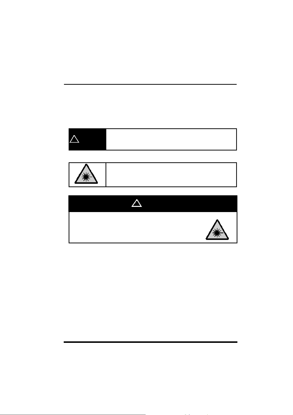
Shows warnings concerning items, places or conditions
! WARNING
zExplanation of Graphic Symbols
This product is equivalent to a JIS/IEC Standard Class 1
Laser device. Essentially, it is safe, but it is dangerous to
view the laser light through a lens or other optical
observation system, so please avoid doing so.
where there is danger or concern with the safety of the
human body.
z Laser Beam
A warning that there is the possibility of danger
from a laser beam.
! WARNING
About Laser Safety
1. JIS/IEC
z With the objective of preventing injury to users of laser products before it can
happen, JIS C 6802
(International Electrical Standards Committee) standards, was stipulated. In
JIS C 6802
degree of danger of the laser component, and preventive measures to assure
safety which should be taken with each class are stipulated.
This product is regarded as Class 1 laser product not only by JIS C 6802
"Safety Standard for Laser Products" but also by IEC60825-1 and EN60825-
1.
, laser products are divided into classes corresponding to the
-1997
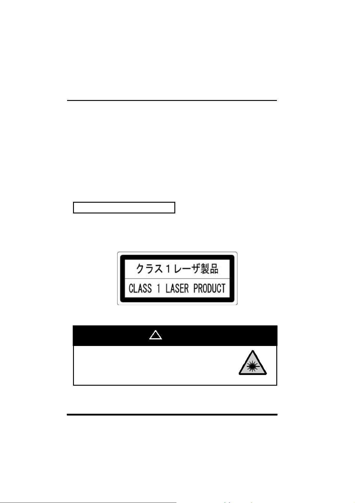
zClass Categorization of the HL-T1
Class 1
x Laser Related Label Indications
The following label is affixed to a side of sensor head according to the
laser device safety standard.
, "Safety Standard for Laser Products", based on IEC
-1997
A.(JIS/IEC)
-1997
! WARNING
This product is equivalent to a JIS/IEC Standard Class 1
Laser device. Essentially, it is safe, but it is dangerous to
view the laser light through a lens or other optical
observation system, so please avoid doing so.
4

2. FDA
z About Export to the United States
If this product is exported to the US as a component of a machine or
instrument, it is governed by the regulations for laser standards of the
FDA (Food and Drug Administration). Use a device which complies with
FDA standards.
The models which comply with FDA standards are as follows.
HL-T1001F
HL-T1005F
HL-T1010F
z With the objective of preventing the occurrence of injuries to persons
using laser products before they happen, the FDA (Food and Drug
Administration) has stipulated the following standard.
Part 1040 (PERFORMANCE STANDARDS FOR LIGHT-EMITTING
PRODUCTS)
z
In this standard, laser products are classified in accordance with the
degree of danger of the laser, and preventive safety measures have been
stipulated which should be executed for each class. (See the list of
required items for laser products.)
This product is classified under this standard as follows.
HL-T1
F Classification (FDA)
Class 2
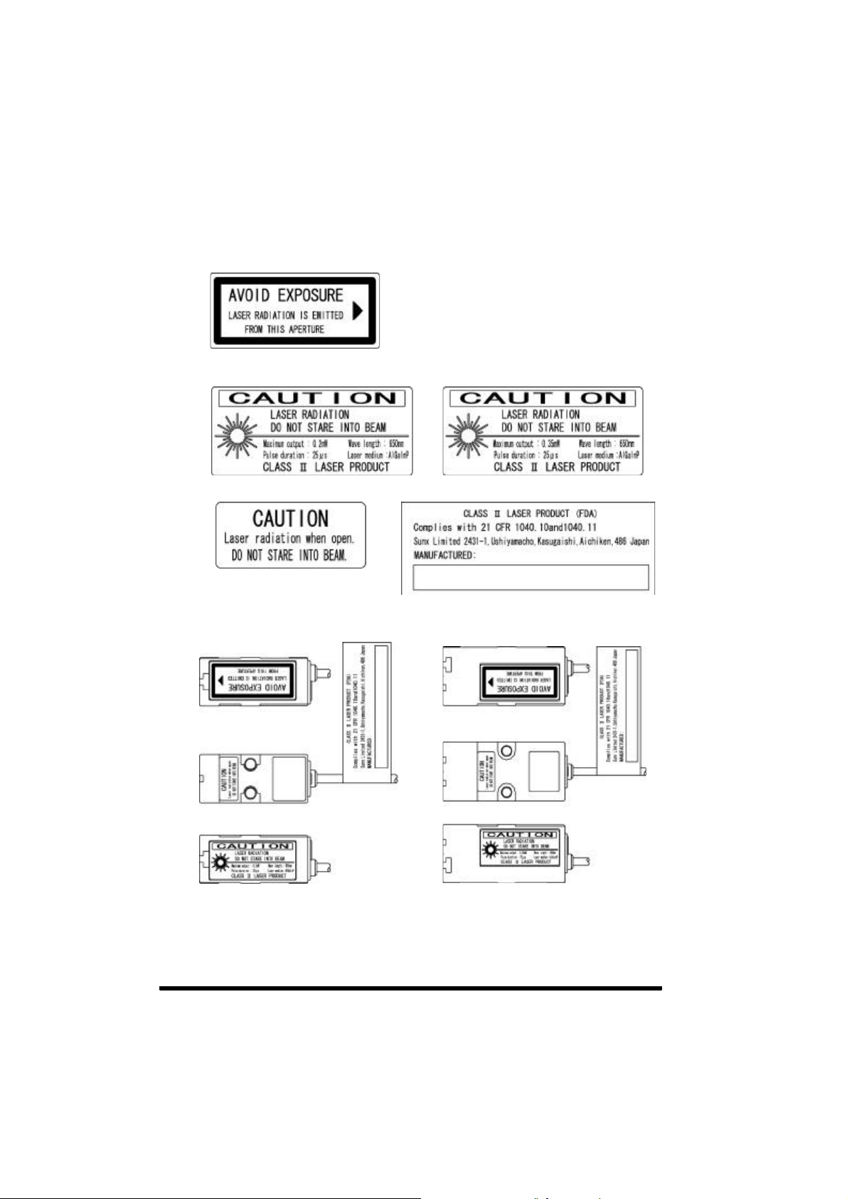
zThe following label is affixed to this product based on the FDA
standard.
(1) Aperture Label
(2) Warning Label
(for the HL-T1001F) (For the HL-T1005F, HL-T1010F)
(3) Protective Housing Label (4) Certification and Identification Label
<Label Position>
HL-T1001F, HL-T1005F HL-T1010F
(Note 1): The label shown above is for
the HL-T1001F.
6

z If this product is exported to the US as a component of a machine or
instrument, it is necessary to submit an initial report on the piece of
equipment as a whole to the CDRH (Center for Devices and Radiological
Health).
It is also necessary to submit the same kind of initial report in cases where
this product is being exported to the US as a maintenance part.
Where to send the initial report:
Center for Devices and Radiological Health
Division of Enforcement III
Department of Health and Human Services
Office of Compliance(HFZ-307)
ATTN: Electronic Product Reports
2098 Gaither Road
Rockville, MD 20910 USA,
prior to the introduction of the reported laser products into
commerce.
If you have specific questions, write to the above address or
call(301)594-4646, Fax(301)594-4672.
z Laser Beam Attenuator
In case there may be a hazard that the eye can be exposed to the laser
beam while working, fit the laser beam attenuator, provided as accessory,
on the aperture of laser radiation.
z Laser Beam Indicator
While the laser beam is being emitted, a green LED on the sensor head
lights up.
This LED can be checked even through the laser protective glass.

z Table of FDA Requirements for Laser Products
1
Requirements
I IIa II IIIa IIIb IV
Class
Performance (all laser products)
2
2
2
Protective housing (1040.10(f)(1))
Safety interlock (1040.10(f)(2))
Location of controls (1040.10(f)(7))
Viewing optics (1040.10(f)(8))
Scanning safeguard (1040.10(f)(9))
R
R
N/A
R
R
R
3,4
R
3,4
R
R
R
R
R
2
R
3,4
3,4
R
R
R
R
R
R
R
Performance (laser systems)
Remote control connector (1040.10(f)(3))
Key control (1040.10(f)(4))
Emission indicator (1040.10(f)(5))
Beam attenuator (1040.10(f)(6))
Reset (1040.10(f)(10))
N/A
N/A
N/A
N/A
N/A
N/A
N/A
N/A
N/A
N/A
R
R
N/A
N/A
R
R
N/A
N/A
N/A
N/A
Performance (specific-purpose products)
Medical (1040.11(a))
Surveying, leveling, alignment (1040.11(b))
Demonstration (1040.11(c))
S
S
S
S
S
S
S
S
S
8
S
S
S
Labeling (all laser products)
R
D
N/A
N/A
R
R
5
5
R
N/A
6
R
R
5
R
R
5
R
R
R
7
9
R
Certification & identification (1010.2, .3)
Protective housing (1040.10(g)(6), (7))
Aperture (1040.10(g)(4))
Class warning (1040.10(g)(1), (2), (3))
Information (all laser products)
R
R
R
User information (1040.10(h)(1))
Product literature (1040.10(h)(2)(γ))
Service information (1040.10(h)(2)(δ))
R
N/A
R
R
R
R
R
R
R
Legend
R - Required
N/A - Not applicable
S - Requirements : Same as for other products of that Class. Also see footnotes.
NP - Not permitted
D - Depends on level of interior radiation
R
R
R
R
R
R
R
R
R
N/A
S
NP
S
R
R
R
R
R
R
R
2
2
R
3,4
3,4
R
R
R
R
R
R
10
10
R
R
13
R
8
8
S
NP
11
11
S
R
5
5
R
R
12
12
R
R
R
R
8
Footnotes
1
Based on highest level accessible during operation.
2
Required wherever & whenever human access to laser radiation above Class
Σlimits is not needed for product to perform its function.
3
Required for protective housing opened during operation or maintenance, if
human access thus gained is not always necessary when housing is open.
4
Interlock requirements vary according to Class of internal radiation.
5
Wording depends on level & wavelength of laser radiation within protective
housing.
6
Warning statement label.
7
CAUTION logotype.
8
Requires means to measure level of laser radiation intended to irradiate the
body.
9
CAUTION if 2.5 mW cm-2 or less, DANGER if greater than 2.5 mW cm-2.
10
Delay required between indication & emission.
11
Variance required for ClassΥb orΦdemonstration laser products and light
shows.
12
DANGER logotype.
13
Required after August 20, 1986.
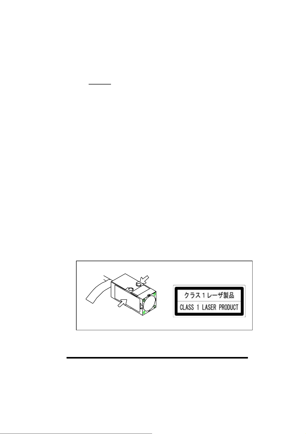
zExport to foreign countries other than the US and use.
In the case of export to areas other than the US or use in those areas, replace
the label on the model that complies to the FDA standards, the HL-T1
F, with the supplied label.
㪩㪼㫇㫃㪸㪺㪼㩷㫋㪿㪼㩷㫃㪸㪹㪼㫃
㪩㪼㫇㫃㪸㪺㪼㩷㫋㪿㪼㩷㫃㪸㪹㪼㫃
Accompanying Label

Handling Precautions
z Never use this product with a sensing device for personnel
!
9#40+0)
Connection
x This product is made to satisfy the specifications when the sensor head is
combined with the controller. In any other combination, not only may it not satisfy
the specifications, but could be the cause of breakdown, so by all means, use it
so that there is a combination of the sensor head and controller.
x Installation of the sensor head and controller, and their removal, must
always be performed with the controller's power turned off.
x If the cables are pulled, it could cause the wires in the cable to become
disconnected, so exercise caution.
Power Supply
x Use this product 10min. after the power is supplied. Immediately on supply
of power, the electrical circuit has yet to stabilize, which may cause variation
in measured values.
x After turning on the power, there is a muting period of approximately
5seconds, so exercise caution.
x Take care that the wrong wiring may damage the sensor.
x Verify that the supply voltage variation is within the rating.
x If power is supplied from a commercial switching regulator, ensure that the
frame ground (F.G.) terminal of the power supply is connected to an actual
ground.
x Make sure to use an isolation transformer for the DC power supply. If an
auto-transformer (single winding transformer) is used, this product or the
power supply may get damaged.
x In case a surge is generated in the used power supply, connect a surge
absorber to the supply and absorb the surge.
protection.
z In case of using devices for personnel protection, use
products which meet standards such as OSHA, ANSI, IEC
etc. for personnel protection applicable in each region or
country.
Wiring
x Do not run the wires together with high-voltage lines or power lines or put
them in the same raceway. This can cause malfunction due to induction.
x Make sure to carry out the wiring in the power supply off condition.
x The linear output is not equipped with a protective circuit against short
circuits. Do not connect the power supply or capacity load directly.
x When using the calculation unit, connect the mutual controller's linear GND.
x Be careful not to apply static electricity to the connector during wiring.
Doing so could cause breakdown.
xExtend the cable between the sensor head and the controller using the exclusive
10

cable, and keep the total length to within 10 meters. Be sure to use the exclusive
extension cable (HL-T1CCJ) to extend the cable from the sensor head. Use the
same type of shielded cable for wiring from the controller.
Environment
x Avoid dust, dirt, and steam.
x Take care that the sensor does not come in direct contact with water, oil,
grease, or organic solvents, such as, thinner, etc.
x In case noise generating equipment (switching regulator, inverter motor,
etc.) is used in the vicinity of this product, connect the frame ground (F.G.)
terminal of the equipment to an actual ground.
x Do not allow any water, oil, fingerprints, etc., which may refract light, or
dust, dirt, etc., which may block light, to stick to the emitting/receiving
surfaces of the sensor head. In case they are present, wipe them with a
clean, soft cloth or lens paper.
x Prevent sunlight or light of the same wavelength or other interfering light
from shining on the sensor head's light receiver. In cases where particular
accuracy is required, install a shade plate, etc. so that the interference light
will not strike the sensor head.
x If the object being measured has a mirror surface or is a transparent body,
it may be impossible to measure it accurate, so please exercise caution.
x When the sensor is mounted, stress should not be applied to the sensor
cable joint and the connector part.
x This sensor is suitable for indoor use only.
x Avoid use at places subject to intense vibrations or shock.
Interchangeability
x The sensor head and controller are interchangeable. It is also possible to
replace only the sensor head.
Mutual Interference
x Mutual interference can be prevented during use by using the sensor head
and controller with a calculation unit (HL-AC1-CL) connected between
them.
Display Values
x This product outputs the judgment of the laser light analog quantity. Since
there is variation in the light intensity between the center and the edges of
the detection area, and emitter side and the receptor side, the "display
value" does not equal “the actual dimensions”, so caution is necessary. Use
the displayed dimensional value as a criterion.
Other
x Absolutely do not attempt to disassemble this product.

Checking the Package Contents
Before using this product, check if the following items have been included in
the package.
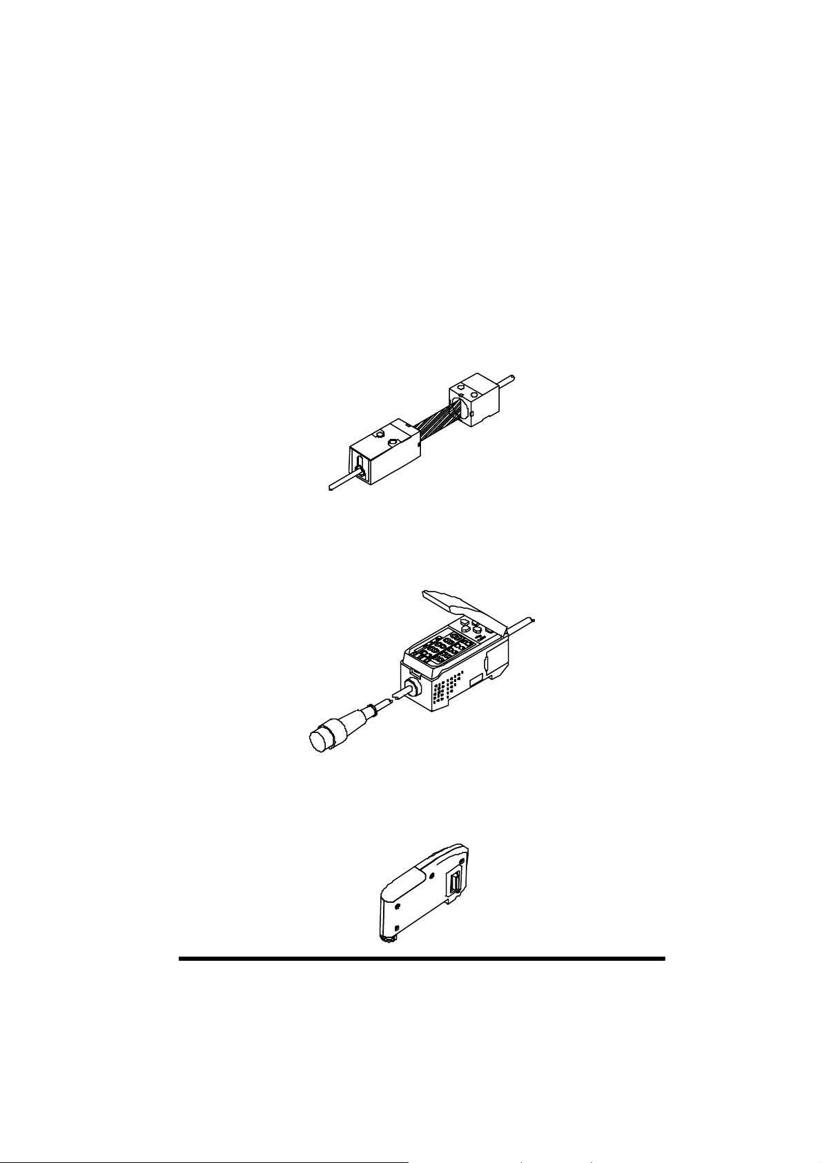
Sensor Head
Body: Emitter, receiver 1 No. each
Sensor head-controller connection cable 1 No.
Sensor head mounting bracket set 2 sets
(Sensor head mounting brackets: 1 No., M3 screws: 2 Nos,
Nut: 1 No.)
Light axis adjustment stickers 2 Nos.
Label set (HL-T1 F only) 1 set
Instruction Manual 1 No.
Controller (optional)
Controller Unit 1 No.
Calculation Unit (optional)
Calculation Unit 1 No.
12
About Markings
Meanings of Symbols
Shows an item that it would convenient to know.
Shows an item about which caution is necessary
during operation.
Shows the item number of related contents in the
manual.
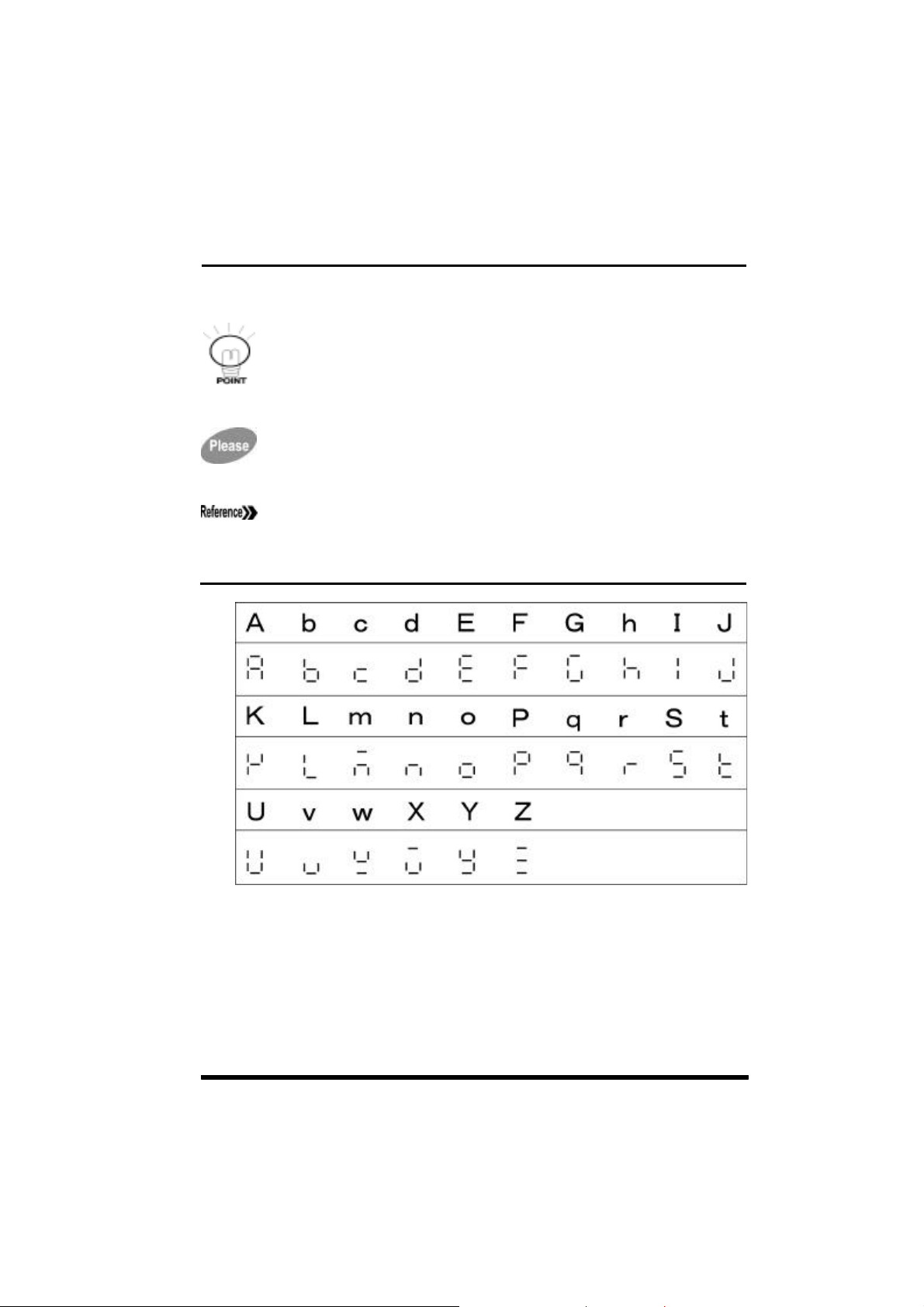
List of controller LED display characters

Memo
14

CHAPTER 1 FOR PERSONS WHO WANT TO USE THE
PRODUCT RIGHT AWAY
Explains connections, wiring and the settings that are necessary for
those who want to use the product right away.
CHAPTER 2 BEFORE USE
Explains the preparations necessary before turning on the power,
such as giving an outline of the product and installing, connecting and
wiring it, etc., and explains the settings to be made when the power is
first turned on.
CHAPTER 3 EXPLANATION OF FUNCTIONS
Provides an outline of the functions and their operation, and gives an
explanation concerning the functions that can be set and setting
methods.
CHAPTER 4 ERRORS: WHEN THIS OCCURS...
Explains concerning the indications and treatment, etc. when each
type of error occurs.
CHAPTER 5 SPECIFICATIONS AND DIMENSIONS
Explains concerning ratings and performance.
CHAPTER 1CHAPTER 2CHAPTER 3CHAPTER 4CHAPTER 5
15

CONTENTS
In order to use this product safely........................................................................ 3
About Laser Safety.................................................................................................... 4
1. JIS/IEC.................................................................................................................. 4
2. FDA ....................................................................................................................... 5
Handling Precautions ............................................................................................... 10
Checking the Package Contents ........................................................................... 12
About Markings .......................................................................................................... 13
List of controller LED display characters........................................................... 13
Contents....................................................................................................................... 16
When this happens... ............................................................................................... 20
CHAPTER 1
1.1 For Persons Who Want To Use The Product Right Away.......................... 24
1.2 Connecting The Sensor Head And Controller .............................................. 25
1.3 Laser Beam Alignment........................................................................................ 27
1.4 Setting Auto Scaling ............................................................................................ 28
1.5 Setting The Standard Laser Beam Reception Volume ............................... 30
1.6 Setting The Linear Output .................................................................................. 31
1.7 Setting The Judgment Output ........................................................................... 33
1.8 Starting Measurement......................................................................................... 35
FOR PERSONS WHO WANT TO USE THE PRODUCT RIGHT AWAY
.... 23
CHAPTER 2 BEFORE USE .................................................................. 37
2.1 Laser Collimated Sensor .................................................................................... 38
2.1.1 Outline of the HL-T1 series ........................................................................... 3 8
2.1.2 Sensor head.................................................................................................... 39
2.1.3 Controller ......................................................................................................... 39
2.1.4 Calculation unit................................................................................................ 39
2.2 Parts Description .................................................................................................. 40
2.2.1 Sensor head.................................................................................................... 40
2.2.2 Controller (optional)........................................................................................ 41
2.2.3 Calculation unit (optional).............................................................................. 42
2.2.4 Controller CH No............................................................................................ 42
2.3 External Inputs and Outputs.............................................................................. 43
2.3.1 Input / output lines .......................................................................................... 43
2.3.2 Inputs ................................................................................................................ 44
2.3.3 Outputs............................................................................................................. 46
2.4 Input / Output Circuit Diagrams........................................................................ 48
2.4.1 NPN output type (HL-AC1)............................................................................ 48
2.4.2 PNP output type (HL-AC1P)......................................................................... 49
2.5 Mounting Method.................................................................................................. 50
2.5.1 Sensor head.................................................................................................... 50
2.5.2 Controller ......................................................................................................... 52
2.6 Connections ........................................................................................................... 53
2.6.1 Connection cable to controller...................................................................... 53
16

2.6.2 Connection cable to sensor head.................................................................53
2.6.3 Cable extension ..............................................................................................54
2.6.4 Controller to calculation unit..........................................................................55
2.7 Laser Beam Alignment ........................................................................................56
2.8 Setting Auto Scaling.............................................................................................57
2.9 Setting the Standard Laser Beam Reception Volume.................................60
CHAPTER 3 EXPLANATION OF FUNCTIONS ..................................... 61
3.1 Outline of Display Operations ...........................................................................63
3.1.1 Operating face.................................................................................................63
3.1.2 Outline of indicators ........................................................................................64
3.1.3 Outline of operating switches ........................................................................65
3.2 Outline of Functions.............................................................................................66
3.2.1 RUN mode .......................................................................................................66
Status transition chart in the RUN mode .........................................................66
3.2.2 THR mode........................................................................................................66
3.2.3 FUN mode........................................................................................................66
Status transition chart in the FUN mode..........................................................67
Here the procedure for scaling settings is shown............................................68
Here the procedure for setting related
Here the procedure for performing display related
Here the procedure for other
Here the procedure for the auto scaling setting is shown. ..............................70
settings is shown......................................70
3.3 List of Default Setting Values ............................................................................71
3.4 Display at Startup..................................................................................................72
3.5 RUN Mode ...............................................................................................................73
3.5.1 Basic operation................................................................................................73
3.5.2 Changing the sub-digital display................................................................... 73
Operation method ...........................................................................................74
Threshold value display ..................................................................................74
Voltage value display ......................................................................................74
Current value display ......................................................................................74
Laser beam reception volume display.............................................................75
Resolution display...........................................................................................75
3.5.3 Zero reset / cancellation ................................................................................76
Setting method................................................................................................76
Cancellation method........................................................................................76
3.5.4 Setting the standard laser beam reception volume................................... 80
Setting method................................................................................................80
3.5.5 Other functions in the RUN mode................................................................81
Timing input.....................................................................................................81
3.6 THR (Threshold) Mode.........................................................................................82
3.6.1 Direct threshold value input........................................................................... 8 3
Changing the numerical value.........................................................................83
Fixing the numerical value ..............................................................................84
3.6.2 Teaching...........................................................................................................85
3.6.3 Teaching positioning .......................................................................................85
settings is shown.......................69
settings is shown...70

Example of teaching positioning..................................................................... 85
Setting method................................................................................................ 85
3.6.4 2-point teaching .............................................................................................. 87
Example of 2-point teaching........................................................................... 87
Setting method................................................................................................ 88
3.6.5 Automatic teaching......................................................................................... 90
Setting method................................................................................................ 91
3.7 FUN (Function) Mode ..........................................................................................93
3.7.1 Basic operation ..............................................................................................93
3.7.2 Basics of mode changes ..............................................................................93
3.7.3 Changing setting values (other than numerical values)..........................94
Set the setting value....................................................................................... 95
3.7.4 Changing setting values (in case of numerical values)...........................96
Setting the numerical value (when normal)....................................................97
Setting the numerical value (when abnormal)................................................98
3.8 Functions That Can Be Set In The FUN Mode..............................................99
3.8.1 Auto scaling function.....................................................................................99
Setting procedure.........................................................................................100
3.8.2 Scaling function..............................................................................................101
Setting procedure..........................................................................................103
If you desire to offset the display value..........................................................104
If you desire to correct the display value to the actual width..........................105
If you desire to use the desired display value................................................107
If you desire to measure the width of the detected object..............................108
3.8.3 Average sampling rate..................................................................................110
3.8.4 Hysteresis width setting................................................................................111
Direct input ....................................................................................................111
Auto hysteresis setting ..................................................................................111
3.8.5 Hold..................................................................................................................112
Normal ...........................................................................................................113
Peak hold.......................................................................................................114
Bottom hold....................................................................................................115
Sample hold...................................................................................................116
Peak to peak hold ..........................................................................................117
Self peak hold................................................................................................118
Self bottom hold.............................................................................................120
Judgment outputs while the hold mode is in use...........................................121
3.8.6 Timer................................................................................................................122
Timer period...................................................................................................122
Without timer..................................................................................................122
Off delay timer ...............................................................................................122
On delay timer ...............................................................................................122
One shot timer...............................................................................................122
3.8.7 Adjacent sensor calculation.........................................................................125
A-B ................................................................................................................125
A+B ...............................................................................................................125
3.8.8 Setting initialization........................................................................................127
3.8.9 Monitor focus function...................................................................................129
18

3.8.10 Differential function..................................................................................... 133
3.8.11 Display reverse function ............................................................................ 135
3.8.12 ECO display function.................................................................................. 136
3.8.13 Display digits limitation .............................................................................. 137
3.8.14 Non-measuring time setting...................................................................... 138
3.8.15 Zero reset memory function...................................................................... 139
3.8.16 Gain switching ............................................................................................. 140
3.8.17 Key lock function......................................................................................... 141
CHAPTER 4 ERRORS: WHEN THIS HAPPENS................................. 143
4.1 Error: When This Happens... ..............................................................................1 44
4.1.1 Error display during normal measurement................................................1 44
4.1.2 Error display when setting numerical values ............................................145
4.1.3 Error display during adjacent sensor calculation.....................................145
4.1.4 Scaling cannot be set...................................................................................146
4.1.5 Monitor focus cannot be set........................................................................146
4.1.6 Threshold values cannot be set..................................................................146
4.1.7 Hysteresis cannot be set. ............................................................................146
4.1.8 Laser deterioration........................................................................................146
CHAPTER 5 SPECIFICATIONS AND DIMENSIONS .......................... 147
5.1 Ratings / Performance.......................................................................................148
5.1.1 Sensor head ..................................................................................................148
5.1.2 Sensor head (FDA compatible)..................................................................149
5.1.3 Controller........................................................................................................150
5.1.4 Calculation unit..............................................................................................152
5.2 Dimensions ...........................................................................................................153
5.2.1 Sensor head ..................................................................................................153
HL-T1001A [Ø1mm type]..............................................................................153
HL-T1001F [Ø 1mm type] .............................................................................154
HL-T1001
HL-T1005A [Ø 5mm type].............................................................................156
HL-T1005F [Ø 5mm type] .............................................................................157
HL-T1005
HL-T1010A [Ø 10mm type]...........................................................................159
HL-T1010F [Ø 10mm type] ...........................................................................160
HL-T1010
MS-HLT1-1
MS-LA3-1 [Sensor head mounting fitting for the HL-T1010
CN-HLT1-1 [Sensor head controller connection cable].................................164
5.2.2 Controller........................................................................................................165
HL-AC1/HL-AC1P........................................................................................165
MS-HLAC1-1 [Controller mounting fitting].....................................................166
5.2.3 Calculation unit..............................................................................................167
HL-AC1-CL ..................................................................................................167
[View with side view attachment (HL-T1SV1) mounted]...........155
[View with side view attachment (HL-T1SV1) mounted]...........158
[View with side view attachment (HL-T1SV2) mounted]...........161
[Sensor head mounting fitting for the HL-T1001 / HL-T1005]
].....................163
..162
APPENDIX............................................................................................. 169
FUNCTION INDEX.....................................................................................................169

When this happens...
z When desiring to set the judgment output threshold value directly.
"3.6.1 Direct threshold value input"
When desiring to teach workpiece positioning.
"3.6.3 Teaching positioning"
When desiring to teach judgment of workpieces for which the dimensions
are unknown.
"3.6.4 2-point teaching"
When desiring to teach judgment of workpieces with an uneven or warped
surface or workpieces in motion.
"3.6.5 Automatic teaching"
When desiring to set the standard light reception volume.
"3.5.4 Setting the standard laser beam reception volume"
When desiring to change the digital display value freely.
"3.8.1 Auto scaling function," "3.8.2 Scaling function"
When desiring to change the response speed or raise the resolution.
"3.8.3 Average sampling rate"
20
When desiring to change the positioning accuracy during operation and
during reset.
"3.8.4 hysteresis width setting"
When desiring to hold the value measured during measuring.
"3.8.5 Hold"
When desir ing to use the off delay timer
"3.8.6 Timer"
When desiring to connect and calculate using 2 sensor heads.
"3.8.7 Adjacent sensor calculation"
When desiring to return to the factory settings.
"3.8.8 Setting initialization "

When desiring to change the output current and voltage range.
"3.8.9 Monitor focus function"
When desiring to detect minute changes.
"3.8.10 Differential function"
When desiring to reverse the display direction.
"3.8.11 Display reverse function"
When desiring to reduce controller current consumption, even if by only a
little.
"3.8.12 ECO display function"
When desiring to stop the laser diode.
"2.3.2 Inputs" (Laser OFF when LD-OFF is input)
When desiring to change the number of columns in the digital display.
"3.8.13 Display digits limitation"
When desiring to make settings freely when measurements cannot be
made.
"3.8.14 Non-measuring time setting "
When desiring to carry out zero reset each time a workpiece is measured.
"3.5.3 Zero reset / Cancellation" , "3.8.15 Zero reset memory
function"
When desiring to set the receptor sensitivity freely.
"3.8.16 Gain switching"
21

Memo
22

CHAPTER 1
FOR PERSONS WHO WANT TO USE THE
PRODUCT RIGHT AWAY
Explains connections, wiring and the settings that are necessary for
those who want to use the product right away.
1.1 For Persons Who Want To Use The Product Right Away..........................24
1.2 Connecting The Sensor Head And Controller...............................................25
1.3 Laser Beam Alignment ........................................................................................27
1.4 Setting Auto Scaling.............................................................................................28
1.5 Setting The Standard Laser Beam Reception Volume................................30
1.6 Setting The Linear Output...................................................................................31
1.7 Setting The Judgment Output............................................................................33
1.8 Starting Measurement .........................................................................................35
23

CHAPTER 2
BEFORE USE
Explains the preparations necessary before turning on the power,
such as giving an outline of the product and installing, connecting and
wiring it, etc., and explains the settings to be made when the power is
first turned on.
2.1 Laser Collimated Sensor.....................................................................................38
2.1.1 Outline of the HL-T1 Series .......................................................................... 38
2.1.2 Sensor head ....................................................................................................39
2.1.3 Controller..........................................................................................................39
2.1.4 Calculation unit................................................................................................39
2.2 Parts Description...................................................................................................40
2.2.1 Sensor head ....................................................................................................40
2.2.2 Controller (optional)........................................................................................41
2.2.3 Calculation unit (optional)..............................................................................42
2.2.4 Controller CH No............................................................................................. 42
2.3 External Inputs and Outputs..............................................................................43
2.3.1 Input / output lines ..........................................................................................4 3
2.3.2 Inputs ................................................................................................................44
2.3.3 Outputs .............................................................................................................46
2.4 Input / Output Circuit Diagrams........................................................................48
2.4.1 NPN output type (HL-AC1)............................................................................48
2.4.2 PNP output type (HL-AC1P) .........................................................................49
2.5 Mounting Method..................................................................................................50
2.5.1 Sensor head ....................................................................................................50
2.5.2 Controller..........................................................................................................52
2.6 Connections ...........................................................................................................53
2.6.1 Connection cable to controller......................................................................53
2.6.2 Connection cable to sensor head.................................................................53
2.6.3 Cable extension ..............................................................................................54
2.6.4 Controller to calculation unit..........................................................................55
2.7 Laser Beam Alignment ........................................................................................56
2.8 Setting Auto Scaling.............................................................................................57
2.9 Setting the Standard Laser Beam Reception Volume.................................60
37

2.1 Laser Collimated Sensor
2.1.1 Outline of the HL-T1 series
The HL-T1 series is a high precision, sophisticated laser collimated sensor, which,
by irradiating the detected object with collimated laser beam, can measure
positioning or width with high precision. It is used as a combination of a sensor
head and controller.
Model No. Description
HL-T1001A Sensor head: Sensing width Ø1mm (Note)
HL-T1005A Sensor head: Sensing width 5mm
HL-T1010A Sensor head: Sensing width 10mm
HL-T1001F FDA compatible sensor head: Sensing width Ø1mm (Note)
HL-T1005F FDA compatible sensor head: Sensing width 5mm
HL-T1010F FDA compatible sensor head: Sensing width 10mm
HL-AC1 Controller: NPN output
HL-AC1P Controller: PNP output
HL-AC1-CL Calculation unit
HL-T1SV1 Side view attachment: Exclusively for the HL-T1001 / HL-T-1005
HL-T1SV2 Side view attachment: Exclusively for the HL-T1010
CN-HLT1-1 Sensor head to controller connection cable: 1.5m
HL-T1CCJ4 Extension cable: 4m
HL-T1CCJ8 Extension cable: 8m
MS-HLT1-1
MS-LA3-1 Sensor head mounting bracket for the HL-T1010
MS-HLAC1-1 Controller mounting bracket
Note: In the case that the detection distance is 0 to 500mm. When it is 500 to 2,000mm, the size
is Ø 1 t o Ø2.5mm.
Sensor head mounting bracket for the HL-T1001 / HL-
T1005
38
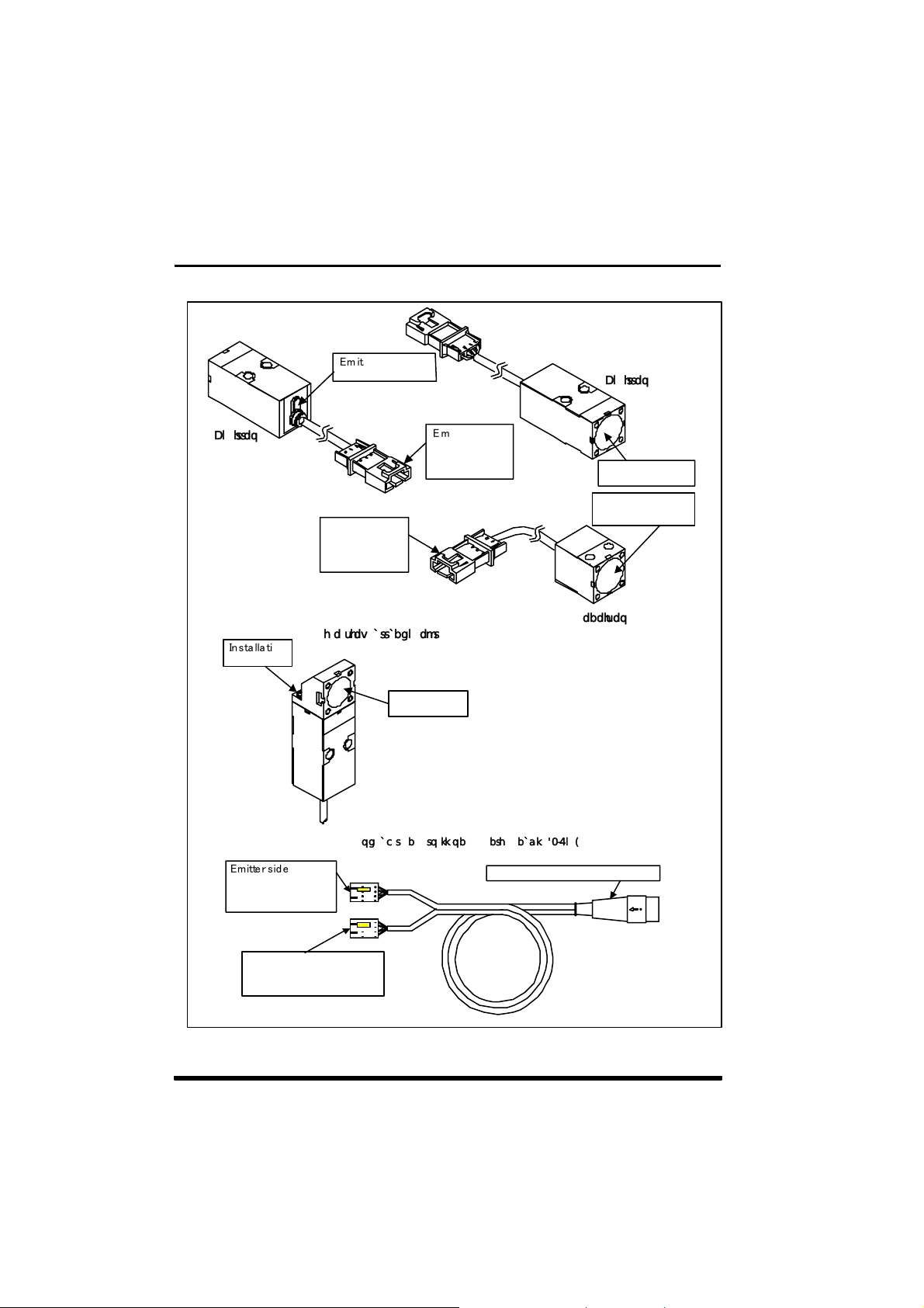
2.1.2 Sensor head
A laser beam shines from the emitter as collimated light and changes in the beam
due to the sensing object are picked up by the receiver, then the resultant values
are converted to electric signals and sent to the controller.
Depending on the sensing width, there are 3 models. Also, through installation of
an optional side view attachment (HL-T1SV), the direction in which the laser
beam shines can be changed. Use the FDA compatible model HL-T1F for
exports to the US.
2.1.3 Controller
The controller receives signals from the sensor head, displays those values and
outputs them to external devices.
It also performs hold and timing control, etc. and 2 connected units can perform
calculations.
2.1.4 Calculation unit
This unit is necessary when 2 controllers are connected together.
A-B and A+B calculations can be performed by connecting 2 units together.
2.2 Parts Description
2.2.1 Sensor head
㪜㫄 㫀㫋㫋㫀㫅 㪾
㫀㫅㪻㫀㪺㪸㫋㫆㫉㩷㩿㪞㫉㪼㪼㫅㪀
㪣㫀㪾㪿㫋㫊㩷㫌㫇㩷㫎㪿㪼㫅
㪼㫄 㫀㫋㫋㫀㫅㪾 㩷㫃㫀㪾 㪿 㫋㪅
㪠㫅㫊 㫋㪸㫃㫃㪸 㫋㫀㫆㫅
㫊㪺㫉㪼㫎
㪜㫄㫀㫋㫋㪼 㫉㩷㫊㫀㪻㪼㩷㫊㪼㫅㫊㫆㫉
㪿㪼㪸㪻 㩷㪺㫆㫅㫅㪼㪺㫋㫀㫆㫅
㪺㫆 㫅 㫅 㪼 㪺㫋 㫆 㫉
㪚㪸㪹㫃㪼㩷㪺㫆㫃㫆 㫉㪑㩷㪞㫉㪸㫐
㪜 㫄 㫀㫋㫋㪼 㫉㩷 㫊㫀㪻 㪼
㫊㪼㫅㫊㫆㫉㩷㪿㪼㪸㪻
㪺㫆㫅㫅㪼㪺㫋㫀㫆㫅
㪺㫆㫅㫅㪼㪺㫋㫆㫉
㪩㪼 㪺㪼 㫀㫍 㪼㫉 㩷㫊㫀㪻 㪼
㫊㪼㫅㫊㫆㫉㩷㪿㪼㪸㪻
㪺㫆㫅㫅㪼㪺㫋㫀㫆㫅
㪺㫆㫅㫅㪼㪺㫋㫆㫉
㪜 㫄 㫀㫋㫋㪼㫉㪃
㫉㪼㪺㪼 㫀 㫍㪼㫉㩷㫌㫅㫀㫋
㪚㫆 㫅㫋㫉㫆㫃㫃㪼 㫉㩷㪺㫆㫅㫅㪼㪺㫋㫀㫆㫅㩷㪺㫆㫅㫅㪼㪺㫋㫆㫉
㪜 㫄 㫀㫋㫋㫀㫅 㪾 㩷㫇 㫆 㫉㫋㫀㫆 㫅
㪩㪼 㪺㪼 㫀㫍㫀 㫅㪾 㩷㫇 㫆 㫉㫋㫀㫆㫅
㩿㪦㫇㫋㫀㪺㪸㫃㩷㪽㫀㫃 㫋㪼㫉㪀
40
㪩㪼㪺㪼㫀㫍㪼㫉㩷㫊㫀㪻 㪼㩷㫊㪼㫅㫊㫆㫉㩷㪿㪼㪸㪻
㪺㫆㫅㫅㪼㪺㫋㫀㫆㫅㩷㪺㫆㫅㫅㪼㪺㫋㫆㫉
㪚㪸㪹 㫃㪼㩷㪺㫆㫃㫆㫉㪑㩷㪙㫃㪸㪺㫂
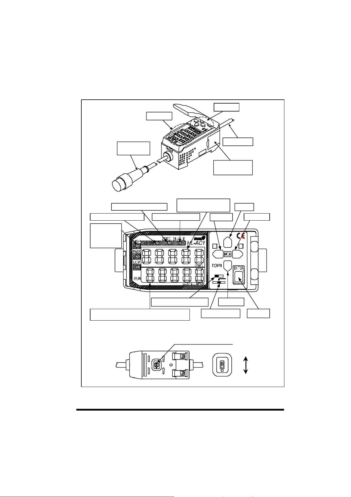
2.2.2 Controller (optional)
㪛㫀㫊㫇 㫃㪸㫐㩷㫌㫅㫀㫋
㪚㫆㫅㫋㫉㫆㫃㩷㫌㫅㫀㫋
㪠㫅㫇㫌 㫋㩷㪺㪸 㪹㫃㪼
㩿㫎㫀㫋㪿㩷㪺㫆 㫅㫅㪼㪺㫋㫆 㫉㪀
㪤 㪸㫀㫅 㪄㪻㫀㪾 㫀㫋㪸㫃㩷㪻㫀㫊 㫇㫃㪸 㫐㩷㩿㪩 㪼㪻 㪀㪃
㪱㪼㫉㫆㩷㫉㪼㫊㪼㫋㩷㫀㫅㪻㫀㪺㪸㫋㫆㫉㩷㩿㪞㫉㪼㪼㫅㪀
㪣㪸㫊㪼 㫉㩷㫃㫀㪾㪿㫋㫀㫅㪾 㩷㫀㫅㪻㫀㪺㪸㫋㫆㫉㩷㩿㪞㫉㪼㪼㫅㪀
㪡㫌㪻㪾 㫄㪼 㫅㫋㩷㫆 㫌㫋㫇㫌㫋
㫀㫅㪻㫀㪺㪸㫋㫆 㫉㫊
㪟㪠㪞㪟㩷㩿㪦㫉㪸㫅㪾㪼㪀
㪧㪘㪪㪪㩷 㩿㪞㫉㪼㪼㫅 㪀
㪣㪦㪮 㩷㩿㪰㪼㫃㫃㫆㫎㪀
㪪㫌㪹㪄㪻㫀㪾㫀㫋㪸㫃㩷㪻㫀㫊㫇㫃㪸 㫐㩷㩿㪰㪼㫃㫃㫆㫎㪀㪃㩷㫋㪿㫉㪼㫊 㪿㫆㫃㪻㩷㫍㪸㫃㫌㪼㪃㩷㫍㫆㫃㫋㪸㪾㪼㩷㪆
㪺㫌㫉㫉㪼㫅㫋㩷㫍㪸㫃㫌㪼㪃㩷㫃㪸㫊㪼㫉㩷㫉㪼㪺㪼㫇㫋㫀㫆 㫅㩷㫍㫆㫃㫌㫄㪼㪃㩷㫉㪼㫊㫆㫃㫌㫋㫀㫆㫅㪃㩷㪼㫋㪺㪅
㪜㫅 㪸㪹 㫃㪼㩷㫀㫅 㪻㫀㪺㪸㫋㫆㫉㩷㩿㪞㫉㪼 㪼㫅㪀
㪫㪿㫉㪼㫊㪿㫆㫃㪻㩷㫍㪸㫃㫌㪼㩷㫊㪼㫃㪼㪺㫋㩷㫊㫎㫀㫋㪺㪿
㫄㪼㪸㫊㫌㫉㪼㫄 㪼㫅㫋㩷㫍㪸㫃㫌㪼㪃
㪽㫌㫅㪺㫋㫀㫆㫅㩷㪻㫀㫊㫇㫃㪸㫐㪃㩷㪼㫋㪺㪅
㪦㫌㫋㫇㫌㫋㩷㪺㪸㪹㫃㪼
㪚㫆㫅㫅㪼㪺㫋㫆㫉㩷㩿㪺㫆㫍㪼㫉
㫆㫇㪼 㫅㫊㩷㪸㫅㪻㩷㪺㫃㫆㫊㪼㫊㪀
㪣㪜㪝㪫 㩷㫂㪼㫐
㪬㪧
㪣
㪟㪣
㪫㪟㪩
㪝㪬㪥㪩㪬㪥
㪛㪦㪮㪥㩷㫂㪼㫐
㪤㫆㪻㪼㩷㫊㪼㫃㪼㪺㫋㩷㫊㫎 㫀㫋㪺㪿
㪬㪧㩷㫂㪼 㫐
㪩㪠㪞㪟㪫㩷㫂㪼㫐
㪩
㪜㪥㪫㩷㫂㪼㫐
The current output / voltage output select switch is located on the
bottom of the controller.
Current / voltage select switch
Voltage output
Current output
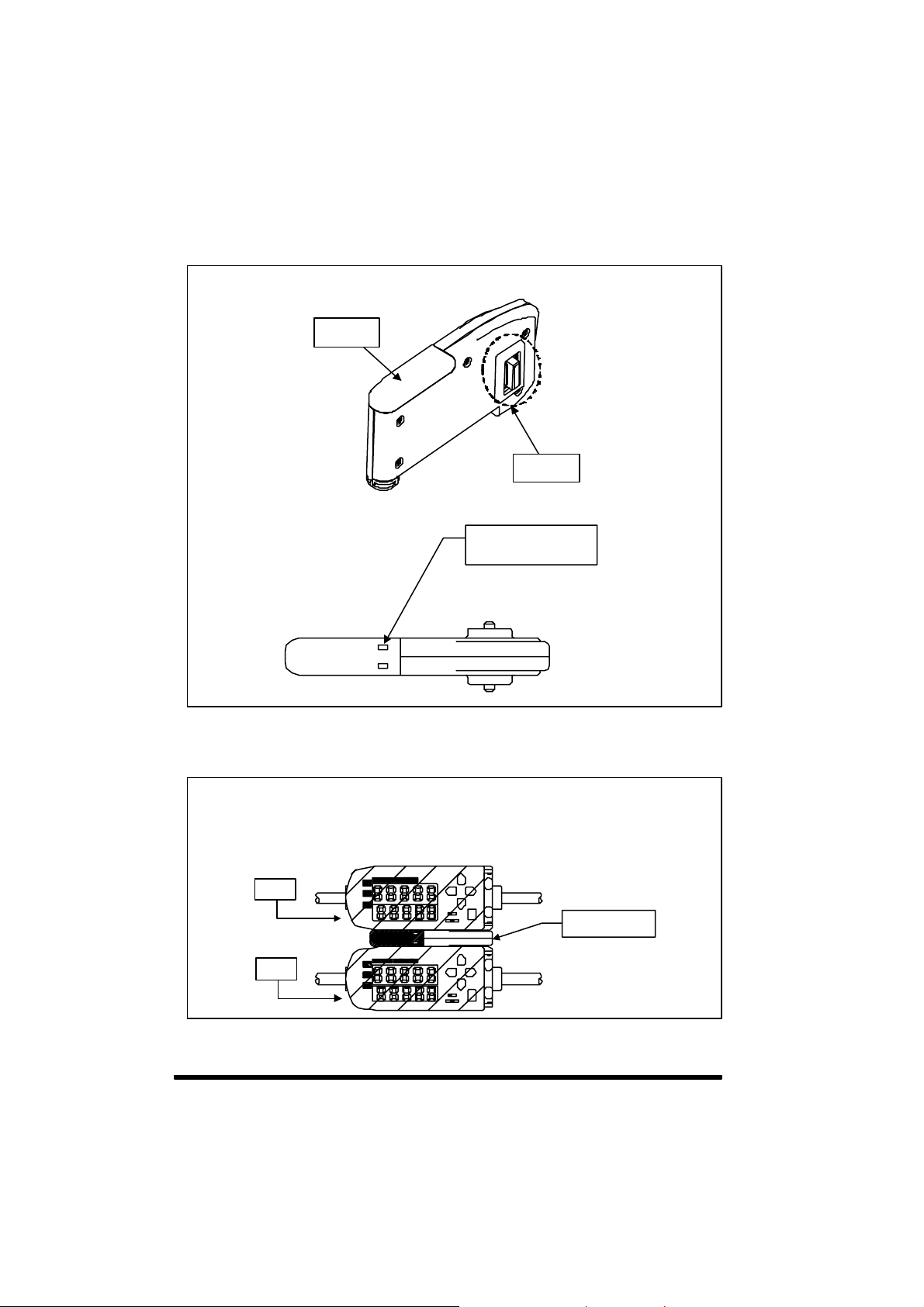
2.2.3 Calculation unit (optional)
㪛㫀㫊㫇㫃㪸㫐
㪚㫆㫅㫅㪼㪺㫋㫆㫉
㪚㫆㫅㫅㪼㪺㫋㫀㫆㫅
㫀㫅㪻㫀㪺㪸㫋㫆㫉㩷㩿㪦㫉㪸㫅㪾㪼㪀
㪣㫀㪾㪿㫋㫊㩷㫌㫇㩷㫎㪿㪼㫅㩷㪺㫆㫅㫅㪼㪺㫋㪼㪻
㫋㫆㩷㪸 㩷㪺㫆㫅 㫋㫉㫆 㫃㫃㪼㫉㪅
2.2.4 Controller CH No.
If 2 controllers are connected using the calculation unit, 1CH comes to the
top side and 2CH comes to the bottom side when the normal display
direction is used.
㪈㪚㪟
㪚㪸㫃㪺㫌㫃㪸㫋㫀㫆㫅㩷㫌㫅㫀㫋
㪉㪚㪟
42
 Loading...