

Panasonic HG-TC101, HG-TC, HG-TC101-P, HG-TC111, HG-TC111-P Instruction Manual
...
INSTRUCTION MANUAL
Transmission-Type Digital Displacement Sensor
/ Controller
HG-TC□
CMJE-HGTC No.0065-82V
Thank you very much for purchasing Panasonic products. Read this Instruction Manual carefully and thoroughly for the correct and optimum use of this product. Kindly
keep this manual in a convenient place for quick reference.
WARNING
● Never use this product as a device for personnel protection.
● When using devices for personnel protection, use products that meet the laws
and standards for personnel protection that apply in each region or country, such
as OSHA, ANSI and IEC.
This document provides a brief summary of mounting, wiring, and other related information.
For detailed information, refer to the “
1 STANDARDS AND REGULATIONS
● This product conforms to the standards and regulations below.
<European Directives>
EMC Directive
2 CONTENTS OF PACKAGE
Controller 1 pc.
Instruction Manual (English / Japanese, Chinese / Korean) 1 pc. each
General Information for Safety, Compliance, and Instructions (23 languages) 1 pc.
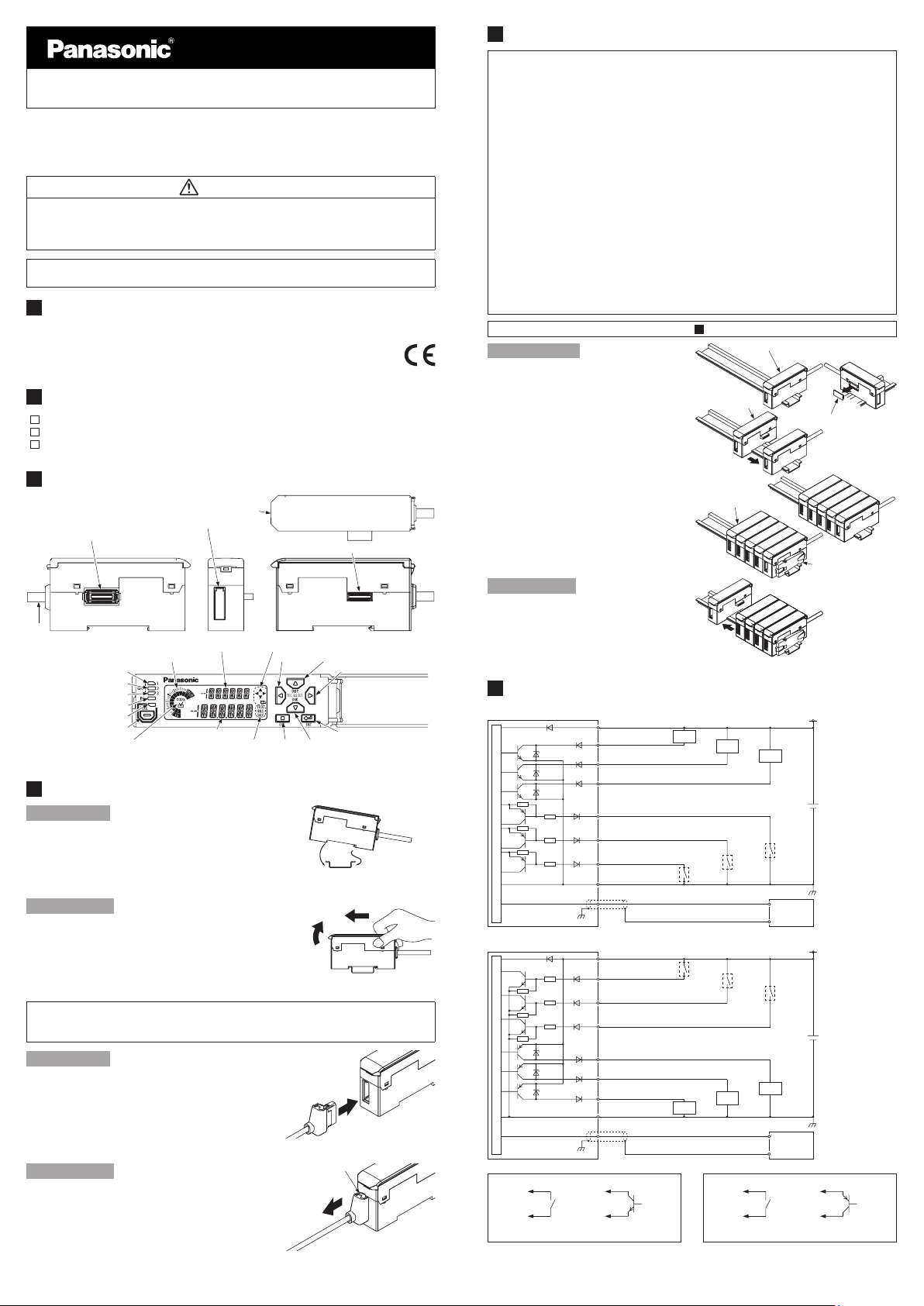
3 DESCRIPTION OF PARTS
Sensor head connection cable connector
Female connector
(Note)
Output 1 indicator (Orange)
Output 2 indicator (Orange)
Output 3 indicator (Orange)
Input indicator (White)
Preset indicator (Green)
Preset key
Note: Not included on the slave unit / Wire-saving type
Copy check mark (Orange)
Digital display / operation cover
Digital display / SUB (Green)
Circle meter (Orange, Green)
Digital display / MAIN (White)
4 MOUNTING
How to mount
1.
Fit the rear part of the mounting section of the
controller on a DIN rail.
2.
Press down the rear part of the mounting sec-
tion of the unit on the DIN rail and t the front
part of the mounting section to the DIN rail.
How to remove
1.
Push the controller forward.
2.
Lift up the front part of the controller to remove
it.
Connecting the sensor head connection cable
●
Always shut off the power before connecting a slave unit to or disconnecting a sensor head connection cable from this product. Risk of controller damage if you attempt connection with the power ON.
How to mount
1.
Insert the sensor head connection cable into
the connector for the sensor head connection
cable on the controller.
Note: Insert the connector rmly. Risk of sensor head or controller damage if not completely connected.
How to remove
1.
Grasp the controller, and while pressing on
the release lever on the connector of the sensor head connection cable, pull the cable toward you to disconnect.
Note:
Do not pull by holding the cable without pressing the release lever, as this can cause cable break or connector break.
HG-T Series User’s Manual
Male connector (Slave unit only)
Guide mark (White)
LEFT key UP key
Status mark (White)
HG-TC113
.
2.
Press
2.
Lift
”.
RIGHT key
ENTER key
DOWN keyEXIT key
35mm width DIN rail
1.
Press forward
1.
Insert
Release lever
1.
Pull out
1.
Insert
5 CONNECTING SLAVE UNITS
● Always shut OFF the power before connecting a slave unit or communication
unit to or disconnecting a slave unit or communication unit from the master unit.
Risk of controller damage if you attempt connection with the power ON.
● Insert the male connector firmly into the female connector. Risk of controller
damage if not completely connected.
● To connect units, the units must be mounted on a DIN rail. Attach end plates
MS-DIN-E
(optional) so as to enclose the connected units at the ends.
● Up to 15 slave units can be connected per master unit. (When communication
unit consolidated: up to 14 slave units)
● When the
HG-T
controller and
HG-S
controller are used in combination, connect
the slave units of the same series to the side closer to the master unit, and
connect the slave units of the different series to the far side.
● When the
functions such as computation function and copy function are restricted. For detailed information, refer to the “
site:https://panasonic.net/id/pidsx/global )
● If the
January 2019, it will not operate properly. Be sure to connect the product to
HG-S
HG-T
controller and
HG-S
controller are used in combination, some
HG-T Series User’s Manual” (our web
HG-T
controller is connected with
.
HG-S
controller manufactured prior to
controller manufactured in or after February 2019.
● When connecting slave units to a master unit, connect only NPN output types, or
only PNP output types. Dissimilar output types cannot be connected together.
4
To mount or remove a controller, refer to “
How to connect
1.
Mount one master unit on the DIN
rail.
2.
Remove the connector cover.
3.
Mount each slave unit one at a time
on the DIN rail. Remove all connec-
MOUNTING
Master unit
Slave unit
”.
Connector cover
tor covers except for the cover on
the last end slave unit.
4.
Slide each slave unit and connect
the female and male connectors.
5.
Attach end plates
tional) with the at side facing in so
MS-DIN-E
as to enclose the connected units
at the ends.
6.
Tighten the screws to fasten the
(op-
End plate
MS-DIN-E
Slide
(Optional)
end plates. Tighten to a torque of
0.3N·m or less.
End plate
MS-DIN-E
(Optional)
How to remove
1.
Loosen the screws on the end
plate.
2.
Remove the end plate.
3.
Slide and remove the controllers,
Slide
one at a time.
6 I/O CIRCUIT DIAGRAMS
NPN output type
●
(Brown) + V (Note 1)
(Black) Output 1
(White) Output 2
(Black / Gray) Output 3
(Pink) External input 1
Main circuit
AGND
PNP output type
●
Main circuit
AGND
*S1 *S2
Non-voltage contact or NPN open collector transistor
0 to +1.2V DC: Valid
+8V to +V DC or open: Invalid
Notes: 1) The
2) Regarding the method of switching analog outputs, refer to the “
3) Use shielded wire for the analog output.
HG-TC111□
(Violet) External input 2
(Pink / Violet) External input 3
(Blue) 0V (Note 1)
(Brown) + V (Note 1)
(Pink) External input 1
(Violet) External input 2
(Pink / Violet) External input 3
(Black) Output 1
(White) Output 2
(Black / Gray) Output 3
(Blue) 0V (Note 1)
or
cables do not have +V or 0V. Power is supplied from the connector of the master unit.
Load
Load
*S1
(Gray) Analog output (Note 2)
(Shielded) Analog ground (Note 3)
*S2
Load
Load
(Gray) Analog output (Note 2)
(Shielded) Analog ground (Note 3)
Non-voltage contact or PNP open collector transistor
+4V to +V DC: Valid
0 to +0.6V DC or open: Invalid
Load
*S1
Analog input
device
*S2
Load
Analog input
device
HG-T Series User’s Manual
*S1
*S2
or
+ V
+
24V DC ±10%
–
0V
+ V
+
24V DC ±10%
–
0V
”.
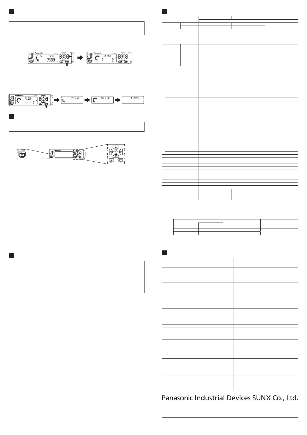
BEAM AXIS ADJUSTMENT FUNCTION AND REFERENCE
7
WAVEFORM REGISTRATION
● Be sure to register a reference waveform after installing the sensor head. If the
reference waveform is not registered, the product cannot measure correctly.
● For detailed information, refer to the “
●
By pressing and holding the RIGHT and ENTER keys simultaneously for 2 seconds,
HG-T Series User’s Manual
”.
you can display the sensor head beam status on the digital display on the controller.
< When beam axis is aligned properly >Long press RIGHT key + ENTER key for 2 seconds
● If the beam axis is not aligned, you conduct adjustment by checking the digital
display on the controller.
● Align the beam axis, and then press the ENTER key to save the reference wave-
form data in the EEPROM of the sensor head beam receiver.
Press ENTER key Reference waveform being registered
Registration of reference
waveform completed
8 MODE SELECTION
For details on the procedures for operating the product, refer to the “
User’s Manual
”.
● The modes and shortcut functions that can be used from the home screen after
the power is turned ON are as follows.
Preset key
Teaching mode (long press LEFT key for 2 seconds)
●
You can set the HIGH set value and LOW set value.
HIGH set value ne adjustment function (short-press UP key)
●
LEFT key
EXIT key
You can ne adjust the HIGH set value as needed.
LOW set value ne adjustment function (short-press DOWN key)
●
You can ne adjust the LOW set value as needed.
Display switching mode (long press UP key for 2 seconds)
●
You can change the display of the digital display / SUB (green) as needed for the task.
Preset (short-press PRESET key)
●
You can perform zero-point adjustment, and shift to any preset value.
You can cancel preset by long-pressing the preset key for 2 seconds.
Bank mode (long press DOWN key for 2 seconds)
●
You can write / read the HIGH set value or LOW set value to / from a specied bank (1 to 3).
Setting mode (long press RIGHT key for 2 seconds)
●
You can change basic settings or congure advanced function settings.
Key lock (long press ENTER key + EXIT key for 3 seconds)
●
This prevents accidental key operations during measurement.
HG-T Series
UP key
RIGHT key
DOWN key
ENTER key
9 CAUTIONS
● For the controller DC power supply, only use a power supply that is isolated by
means of an isolation transformer or otherwise.
● Risk of short-circuiting and damage to the controller or power supply if a trans-
former such as an auto transformer is used. Risk of short-circuiting and damage
to the controller or power supply if incorrectly mounted or connected.
●
The controller
If used with other than the special sensor head option, the specications will not
be met and product malfunctioning or damage may occur.
● This product has been developed / produced for industrial use only.
● This product uses an EEPROM. The EEPROM has a service life of one million
setting operations.
● Do not use this product outside the range of the specications. Risk of an accident
and product damage. There is also a risk of a noticeable reduction of service life.
● Verify that the supply voltage uctuations are within the rating.
● If power is supplied from a commercial switching regulator, ensure that the frame
ground (F.G.) terminal of the power supply is connected to an actual ground.
● Do not use during the initial transient time after the power supply is switched ON.
● Make sure that the power supply is OFF while performing wiring or connecting a
slave unit work.
●
Take care that short-circuit of the load or wrong wiring may burn or damage the product.
●
After you have completed wiring work, check the wiring carefully before switching on the power.
● Do not wire in parallel with a high-voltage line or power line, or run through the
same conduit. Risk malfunctioning due to induction.
●
Do not apply stress such as excessive bending or pulling to the extracted part of a cable.
● This product is suitable for indoor use only.
● Avoid dust, dirt, and steam.
●
Do not use this sensor in places where it may come in contact with corrosive gas, etc.
●
Ensure that the product does not come into contact with organic solvents such as thinner.
● Ensure that the product does not come into contact with strong acid or alkaline.
● Ensure that the product does not come into contact with oil or grease.
●
This product cannot be used in an environment containing ammable or explosive gases.
● Performance may not be satisfactory in a strong electromagnetic eld.
● This product is a precision device. Do not drop or otherwise subject to shock. Risk
of product damage.
● Never attempt to disassemble, repair, or modify the product.
● When the product becomes unusable or unneeded, dispose of the product appro-
priately as industrial waste.
HG-TC
□ is designed to be used with the special sensor head
HG-T
□.
10
SPECIFICATIONS
Type
Model No.
Applicable sensor head
Number of connectable units
Supply voltage 24V DC ±10%, including 0.5V ripple (P-P)
Current consumption (Note 2)
Analog output
(Switching type)
(Note 3)
Control output
(
Output 1 / Output 2 / Output 3)
External input
(Input 1 / Input 2 / Input 3)
Sampling cycle 1 ms (standard sampling) / 0.5 ms (high-speed sampling)
Average count (Response time)
(Note 5)
Display resolution 1µm
Display range -199.999 to 199.999mm
Protection IP40 (IEC)
Pollution degree 2
Ambient temperature
Ambient humidity 35 to 85% RH, Storage: 35 to 85% RH
Operating altitude 2,000m or less (Note 6)
Material Case: Polycarbonate, Cover: Polycarbonate, Switches: Polyacetal
Cable
Weight (controller only) Approx. 140g Approx. 140g Approx. 60g
Notes: 1) Measured at a supply voltage of +24V DC and an ambient temperature of +20°C, unless otherwise indicated.
2) Current consumption does not include analog current output.
3) Linearity is the value to the digital measurement value based on the F.S. = 16mA when analog current is out-
4) When slave units are connected to the master unit, the maximum sink current / source current of the control
5) Average count (response time) gures have been calculated based on a sampling cycle of 1ms (standard
6) Do not use or store in an environment pressurized to atmospheric pressure or higher at an altitude of 0m.
11
Error
Display
E100
E110 Number of connectable units exceeded.
E120
E130
E140
E150
E160
E170
E180 Cannot communicate between controllers.
E200
E230
E240 Beam emitter abnormality Replace the sensor head.
E500 Unable to preset by external input.
E510
E600 Unable to write to the EEPROM of the controller. • Switch the power OFF then ON, and execute initialE610 Unable to read from the EEPROM of the controller.
E620
E630
E640
E700
E900
E910
E911
E912
E920
NPN output
PNP output
Analog voltage
output
Analog current
output
Short-circuit protection Incorporated (automatic reset type)
Decision output N.O./N.C. switching type
Alarm output Open when alarm
Trigger input Input time 2ms or more (ON)
Laser emission halt input Input time 20ms or more (ON)
Preset input Input time 20ms or more (ON)
Reset input Input time 20ms or more (ON)
Bank input A / B Input time 20ms or more (ON)
put or the F.S. = 4V when analog voltage is output.
output and ambient temperature vary depending on the number of connected slave units as shown below.
Number of connected slave units
1 to 7 units 1 to 6 units 20mA
8 to 15 units 7 to 14 units 10mA
sampling). Response time varies if the sampling cycle is set to 0.5ms (high-speed sampling). Refer to the
HG-T Series User’s Manual
“
ERROR DISPLAY
Both NPN output types and PNP output types are connected.
Cannot communicate between controllers.
The calculation function is valid but no slave units are connected.
The calculation function is valid but an insufficient
number of slave units are connected.
The saved number of connected units does not match
the actual number of connected units.
The copy function was executed using the master
unit, but the copy operation does not start due to abnormal operation of the slave unit.
• Sensor head not connected.
• Broken wire in sensor head connection cable.
• Sensor head failure.
• Sensor head other than the
nected.
Paired sensor heads are both beam emitters or both beam receivers.
Beam alignment function was used while the laser
emission halt input was ON.
The EEPROM of the controller write count is over the
service life of 1 million.
Unable to write to or read from the EEPROM of the
sensor head or beam receiver.
Unable to write to or read from the non-volatile memory of the sensor head or beam emitter.
The detection output load has short-circuited and ex-
cessive current is owing.
An error has occurred in the internal controller.
Master unit Slave unit
High performance type Wire-saving type
HG-TC101 HG-TC111
HG-TC101-P HG-TC111-P
Up to 15 slave units can be connected per master unit.
(When communication unit consolidated: up to 14 slave units)
100mA or less (when sensor head is connected) (Note 2)
• Voltage output range: 1 to 5V / F.S. (default value)
• Alarm output: 5.2V
• Linearity: ±0.05% F.S.
• Output impedance: 100Ω MAX.
•
Current output range: 4 to 20mA / F.S. (default value)
• Alarm output: 0mA
• Linearity: ±0.25% F.S.
• Load impedance: 250Ω MAX.
<NPN output type>
NPN open-collector transistor
• Maximum sink current: 50mA (Note 4)
•
Applied voltage: 30V DC or less (between output and 0V)
• Residual voltage: 1.5V or less (at 50mA sink current)
• Leakage current: 0.1mA or less
<PNP output type>
PNP open-collector transistor
• Maximum source current: 50mA (Note 4)
•
Applied voltage: 30V DC or less (between output and +V)
•
Residual voltage: 1.5V or less (at 50mA source current)
• Leakage current: 0.1mA or less
<NPN output type>
Non-contact input or NPN open-collector transistor
• Input condition
Invalid: +8V to +V DC or open
Valid: 0 to +1.2V DC
• Input impedance: Approx. 10kΩ
<PNP output type>
Non-contact input or PNP open-collector transistor
• Input condition
Invalid: 0 to +0.6V DC or open
Valid: +4V to +V DC
• Input impedance: Approx. 10kΩ
1 time (2ms), 2 times (3ms), 4 times (5ms), 8 times (9ms), 16 times (17ms), 32 times (33ms), 64 times (65ms),
128 times (129ms), 256 times (257ms), 512 times (513ms), 1,024 times (1,025ms) switching type
-10 to +50°C (No dew condensation or icing allowed) (Note 4), Storage: -20 to +60°C
0.2mm2 2-core (brown, blue
lead wires) / 0.15mm2 7-core
composite cable, 2m long
When communication unit consolidated
”.
Description Action
Maximum sink current / source
current of control output
HG-T
series is con-
HG-T□
0.15mm2 7-core composite cable, 2m long
Connect only units of the same output type.
Connect no more than 15 slave units per master unit.
(When communication unit consolidated: up to 14 slave units)
Switch OFF the power, make sure the controllers are
connected correctly, and then switch ON the power again.
Change calculation mode to OFF.
Change calculation mode to OFF, or change the calcu-
lation application selection setting.
Set the number of connected units check function to
OFF.
Switch the power OFF and switch it back ON again,
and then check if the slave unit is operating properly.
Switch OFF the power, make sure the controllers are connected correctly, and then switch ON the power again.
• Check if the sensor head is correctly connected.
• Check if there is a broken wire in the sensor head
connection cable. If there is a broken wire in the
sensor head connection cable, replace the cable.
• Replace the sensor head.
HG-T
• Connect
Check the connected sensor heads.
Check if the power just been switched on or reset has
just been input, or if a display value is outside the display upper/lower limit or an alarm has occurred.
Turn the laser emission halt input OFF, and then align
the beam axis.
ization of the controller from setting mode.
• If the controller does not recover after the above, it
is possible that the EEPROM write count is over
1 million. Replace the controller.
• Switch the power OFF then on, and execute initialization of the controller from setting mode.
• If the problem cannot be corrected by the above action, please contact our company.
Switch OFF the power and check the load.
Switch the power OFF then ON, and execute initialization of the controller from setting mode.
series sensor head.
HG-TC113
-
-
-
-
-
-
-
-
-
-
-
-
-
Ambient temperature
-10 to +45°C
https://panasonic.net/id/pidsx/global
Overseas Sales Division (Head Ofce)
2431-1 Ushiyama-cho, Kasugai-shi, Aichi, 486-0901, Japan
Phone: +81-568-33-7861 FAX: +81-568-33-8591
For sales network, please visit our website.
PRINTED IN JAPAN © Panasonic Industrial Devices SUNX Co., Ltd. 2018
 Loading...