

panasonic HG-T User Manual

Thru-Beam Type Digital Displacement Sensor
HG-T series
User’s Manual
WUME-HGT-6
2020.11 panasonic.net/id/pidsx/global

(MEMO)
2 WUME-HGT-6
Introduction
Thank you for purchasing an HG-T series thru-beam digital displacement sensor.
Before using this product, read and understand this User's Manual. Use the product correctly
and in the optimum manner.
Keep this manual in a safe location for reference whenever necessary.
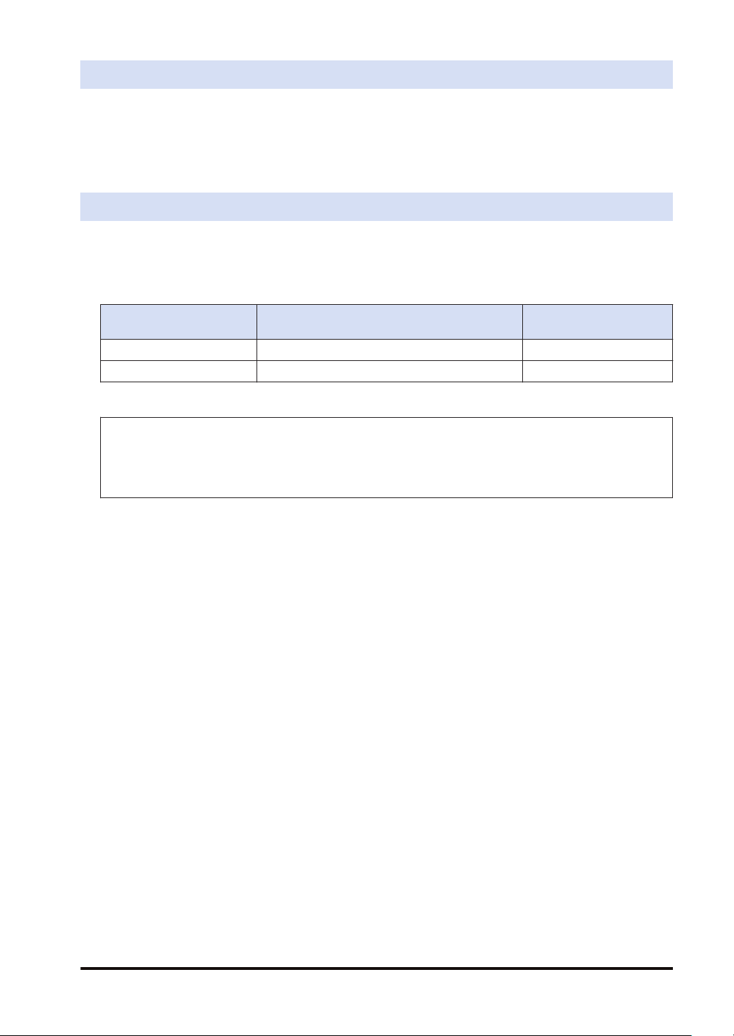
Types of Manuals
The following user’s manuals are available for the HG-T series. Refer to the appropriate manual
according to your need.
The user’s manuals are also available for download from our website (https://panasonic.net/id/
pidsx/global).
Unit name or purpose of
use
HG-T Control Unit HG-T User’s Manual WUME-HGTM
HG-T Configuration Tool HG-T Configuration Tool User’s Manual WUME-HGTCT
Manual name Manual code
Please note
1. No part of this manual may be reproduced or reprinted in any form or by any means without prior written
permission from Panasonic.
2. The contents of this manual are subject to change without notice for future improvement.
3. This manual has undergone strict quality control; but should you discover any dubious information,
mistakes, misplaced pages, or missing pages, please contact your local dealer.
WUME-HGT-6 iii

Manual Configuration
Chapter 1 Before Using This Product
Chapter 2 System Configuration This chapter explains the system configuration.
Chapter 3 Overview of HG-T Series
Chapter 4 Installation and Connections
Chapter 5 Basic Usage
Chapter 6 Setting up General Functions
Chapter 7 Setting up Extended Functions
Chapter 8 Specifications and Dimensions This chapter explains the specifications and dimensions.
Chapter 9 Maintenance This chapter explains maintenance and inspection.
Chapter 10 Troubleshooting This chapter explains troubleshooting and error codes.
Chapter 11 Appendix This chapter provides menu structure.
This chapter explains safety and handling precautions, laser
safety standards, and other information that should be
checked before using this product.
This chapter explains the principle of measurement and how
to use this product when controllers are connected.
This chapter explains installation, connections, wiring, and
other work.
This chapter explains the flow of operations up to
measurement startup, the base screen displayed when the
power is turned ON, and basic operations.
This chapter explains details and settings for general
functions.
This chapter explains details and settings for extended
functions.
Product Version
This manual has been created based on the product functions available as of November 2020.
For product version information, refer to "1.6 Product Version and Functions".
iv
WUME-HGT-6

Table of Contents
1 Before Using This Product................................................................... 1-1
1.1 Safety Precautions (Always observe) .................................................1-2
1.2 Handling Precautions..........................................................................1-3
1.3 Laser Safety Standards ......................................................................1-5
1.3.1 IEC / JIS / GB................................................................................... 1-5
1.3.2 FDA.................................................................................................. 1-6
1.4 Terminology.........................................................................................1-9
1.5 Contents of Package...........................................................................1-10
1.6 Product Version and Functions...........................................................1-12
2 System Configuration........................................................................... 2-1
2.1 System Configuration..........................................................................2-2
2.2 Description of Parts.............................................................................2-3
2.2.1 Controller ......................................................................................... 2-3
2.2.2 Sensor head..................................................................................... 2-5
2.2.3 Sensor Head Connection Cable ...................................................... 2-6
2.2.4 Side View Attachment...................................................................... 2-6
3 Overview of HG-T Series ......................................................................3-1
3.1 Principle of Measurement ...................................................................3-2
3.2 Role of Controllers ..............................................................................3-3
3.3 Using Connected Controllers..............................................................3-4
4 Installation and Connections...............................................................4-1
4.1 Mounting the Controller.......................................................................4-2
4.1.1 Mounting on a DIN Rail.................................................................... 4-2
4.1.2 Removing from a DIN Rail ............................................................... 4-2
4.1.3 Controller Wiring Connection Diagrams........................................... 4-3
4.2 Attaching the Sensor Head.................................................................4-4
4.3 Connecting the Sensor Head Connection Cable ................................4-5
4.3.1 Connecting to the Sensor Head....................................................... 4-5
4.3.2 Disconnecting from the Sensor Head .............................................. 4-6
4.3.3 Connecting to the Controller ............................................................ 4-6
4.3.4 Disconnecting from the Controller.................................................... 4-7
4.3.5 Connecting and Disconnecting to / from Controller Connector........ 4-7
4.4 Connecting Controllers .......................................................................4-10
4.4.1 How to Connect ............................................................................... 4-11
4.4.2 How to Remove ............................................................................... 4-13
4.5 Mounting the Side View Attachment...................................................4-14
5 Basic Usage...........................................................................................5-1
5.1 Using the Base Screen .......................................................................5-2
5.1.1 Functions of Operation Pad and Display Unit .................................. 5-2
WUME-HGT-6
v
5.2 Flow of Operations up to Measurement Startup .................................5-6
5.3 Explanation of Basic Operation...........................................................5-8
5.3.1 Checking the Beam Axis.................................................................. 5-8
5.3.2 Adjusting the Beam Axis .................................................................. 5-9
5.3.3 Reference Waveform Registration................................................... 5-14
5.3.4 Teaching........................................................................................... 5-16
5.4 Operation Mode ..................................................................................5-22
5.4.1 Auto Edge Detection Mode (
5.4.2 Edge Detection Mode ( ).......................................................... 5-23
5.4.3 Outer diameter/Width Detection Mode (
5.4.4 Inner Diameter/Gap Detection Mode (
5.4.5 Central Position Detection Mode ( ).................................... 5-25
5.4.6 User Assigned Edge Detection Mode ( ) ........................... 5-27
) ............................................ 5-22
) ............................. 5-24
) ................................ 5-25
5.5 Settings on the Base Screen (Using Shortcut Keys) ..........................5-30
5.5.1 Display Switching Mode................................................................... 5-30
5.5.2 Preset............................................................................................... 5-33
5.5.3 Saving and Loading Settings to / from Banks .................................. 5-35
5.5.4 Key Lock .......................................................................................... 5-38
5.5.5 Sensitivity Settings........................................................................... 5-40
5.6 Self-monitoring Function.....................................................................5-47
5.6.1 Using the Self-monitoring Function.................................................. 5-47
5.6.2 Statuses and Measures ................................................................... 5-48
6 Setting up General Functions..............................................................6-1
6.1 Flow of Measurement Data.................................................................6-2
6.2 Setting Operation List .........................................................................6-4
6.3 Detection Settings (
6.3.1 Operation Mode ( ) ............................................................... 6-9
6.3.2 Measurement Direction ( ).................................................... 6-10
6.3.3 Average Count (Response Time)( )........................................ 6-11
) ..............................................................6-9
6.4 Basic Settings ( ).......................................................................6-14
6.4.1 HIGH Set Value ( ).................................................................. 6-14
6.4.2 LOW Set Value ( )................................................................... 6-15
6.4.3 Hysteresis ( ) ........................................................................ 6-17
6.4.4 Teaching Types ( ) .................................................................. 6-20
6.4.5 Tolerance <±> (
6.4.6 Preset Value ( ) ....................................................................... 6-22
6.4.7 Preset Data Selection ( ) ........................................................ 6-23
6.4.8 Preset Save ( ) ..................................................................... 6-24
6.4.9 Reference Waveform Save (
6.4.10 Output Operation ( ) ........................................................... 6-26
6.4.11 Analog Output Selection ( ) ................................................ 6-27
6.4.12 Menu Display Settings ( ) ....................................................... 6-28
) ................................................................... 6-21
).............................................. 6-25
6.5 Initialization ( )...........................................................................6-30
vi
WUME-HGT-6
6.6 Maintenance ( ).......................................................................6-31
7 Setting up Extended Functions ...........................................................7-1
7.1 Setting Operation List .........................................................................7-3
7.2 Advanced Settings (
7.2.1 Hold Settings ( )........................................................................ 7-9
7.2.2 Simultaneous Input ( )(For Master Units Only)..................... 7-17
7.2.3 External Inputs ( ) ................................................................... 7-19
7.2.4 External Outputs ( ) .............................................................. 7-21
7.2.5 External Output Delay Timer Selection ( )............................ 7-28
7.2.6 Number of Digits Displayed ( )................................................ 7-35
7.2.7 Analog Scaling ( )................................................................. 7-36
7.2.8 Eco Mode ( )............................................................................. 7-41
7.2.9 Alarm Settings ( ).................................................................... 7-42
7.2.10 Key Lock Function Selection ( ) ......................................... 7-47
7.2.11 Interference Prevention Function ( )(For Master Units
Only) ................................................................................................. 7-48
7.2.12 Sampling Cycle (
7.2.13 Reverse of Measured Value ( )........................................... 7-51
) .............................................................7-9
).............................................................. 7-50
7.3 Calculation Settings ( )(For Master Units Only)...........................7-53
7.3.1 Calculation Mode (
7.3.2 Calculation Application Selection (
7.4 Copy Settings (
7.4.1 Copy Individual Selection ( )(For Master Units Only) ........... 7-59
7.4.2 Copy Batch Selection ( )(For Master Units Only) ................. 7-62
7.4.3 Copy Execution ( )(For Master Units Only) .......................... 7-62
7.4.4 Copy Lock (
) .........................................................................7-59
)(For Slave Units Only) ......................................... 7-63
).................................................................. 7-53
)....................................... 7-54
7.5 Bank Settings (
7.5.1 Bank Save Selection ( )........................................................ 7-65
) ..........................................................................7-65
7.6 Calibration Settings ( ) ..............................................................7-67
7.6.1 Calibration Selection (
)........................................................ 7-67
7.7 Tab Cancellation Function...................................................................7-71
7.7.1 Setting up the Functions .................................................................. 7-71
7.7.2 Operations when the Tab is Detected .............................................. 7-73
7.7.3 Response Time when the Tab Cancellation Function Is Enabled .... 7-73
7.7.4 Checking the Hold Status ................................................................ 7-74
7.7.5 Precautions when Using the Tab Cancellation Function .................. 7-75
8 Specifications and Dimensions...........................................................8-1
8.1 Specifications......................................................................................8-2
8.1.1 Controller ......................................................................................... 8-2
8.1.2 Sensor Head .................................................................................... 8-9
8.2 Dimension Drawings...........................................................................8-11
8.2.1 Controller ......................................................................................... 8-11
8.2.2 Sensor Head .................................................................................... 8-13
WUME-HGT-6
vii

8.2.3 Side View Attachment...................................................................... 8-14
9 Maintenance ..........................................................................................9-1
9.1 Maintenance and Inspection...............................................................9-2
9.1.1 Maintenance Precautions ................................................................ 9-2
9.1.2 Main Inspection Items ...................................................................... 9-2
10 Troubleshooting..................................................................................10-1
10.1 Troubleshooting ................................................................................10-2
10.2 Error Messages.................................................................................10-5
Appendix Appendix ................................................................................App-1
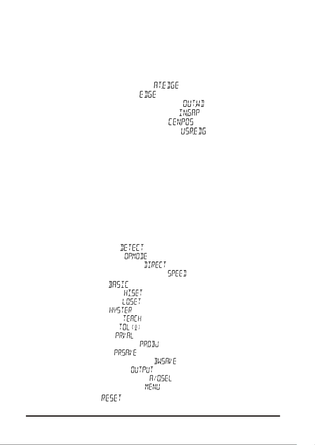
Menu Structure (General Function Display)...............................................App-2
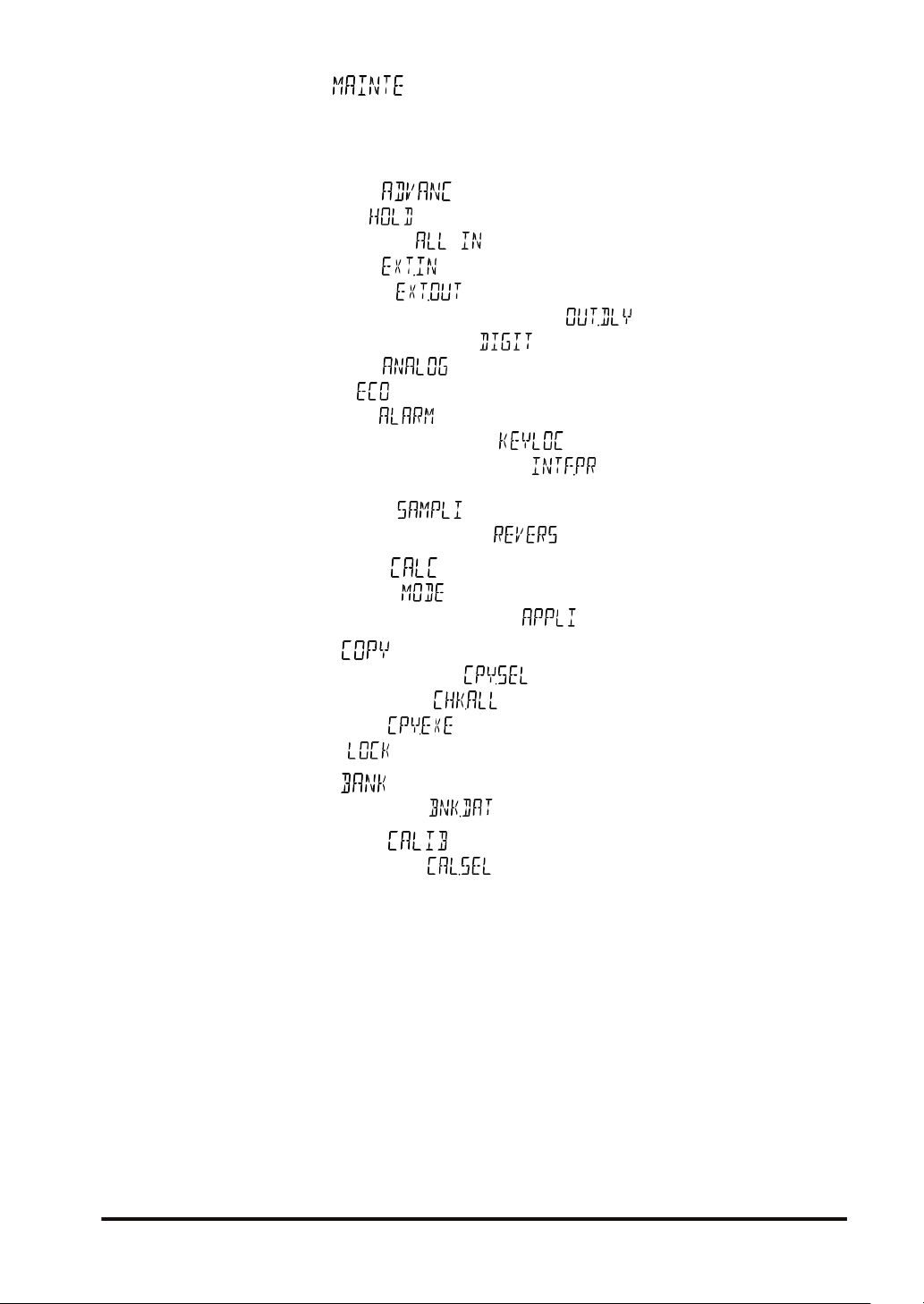
Menu Structure (Extended Function Display) ............................................App-4
viii WUME-HGT-6

1 Before Using This Product
1.1 Safety Precautions (Always observe) .................................................1-2
1.2 Handling Precautions..........................................................................1-3
1.3 Laser Safety Standards ......................................................................1-5
1.3.1 IEC / JIS / GB................................................................................... 1-5
1.3.2 FDA.................................................................................................. 1-6
1.4 Terminology.........................................................................................1-9
1.5 Contents of Package...........................................................................1-10
1.6 Product Version and Functions...........................................................1-12
WUME-HGT-6 1-1
1.1 Safety Precautions (Always observe)
1.1 Safety Precautions (Always observe)
This section explains important rules that must be observed to prevent personal injury and
property damage.
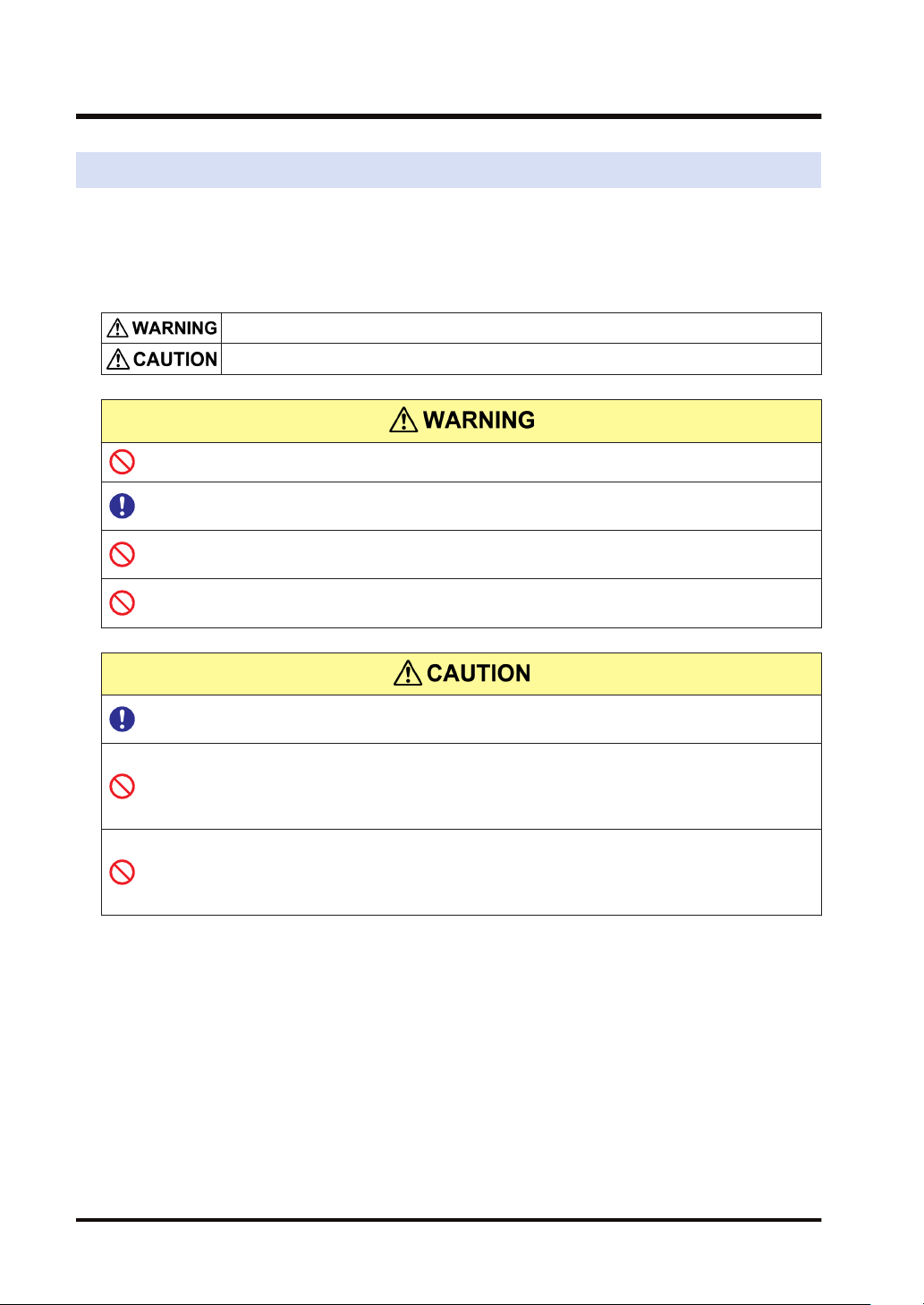
■
Safety precautions items are classified into “WARNING” and “CAUTION”
depending on the level of hazard.
Risk of death or serious injury.
Risk of minor injury or property damage.
● Never use this product as a sensing device for personnel protection.
● For sensing devices for personal protection, use products that conform to the laws and
standards related to personal protection in each country, such as OSHA, ANSI, and IEC.
● This product is designed to inspect (judge or measure) objects and so must not be used
to ensure safety, for example, to prevent accidents that affect human lives or property.
● Do not look at or touch direct laser beams or other reflections of light, as doing so is
dangerous.
● For the controller DC power supply, only use a power supply that is isolated by means of
an isolation transformer or otherwise.
● There is a risk of short-circuiting and damage to the controller or power supply if a
transformer such as an autotransformer is used. There is a risk of short-circuiting and
damage to the controller or power supply if the controller is incorrectly mounted or
connected.
● The HG-TC series controller is designed to be used with the HG-T series special-purpose
sensor head to satisfy the specifications. If the controller is used with any sensor head
other than the special-purpose sensor head, the specifications will not be satisfied and
malfunctioning or another problem may occur.
1-2 WUME-HGT-6
1.2 Handling Precautions
1.2 Handling Precautions
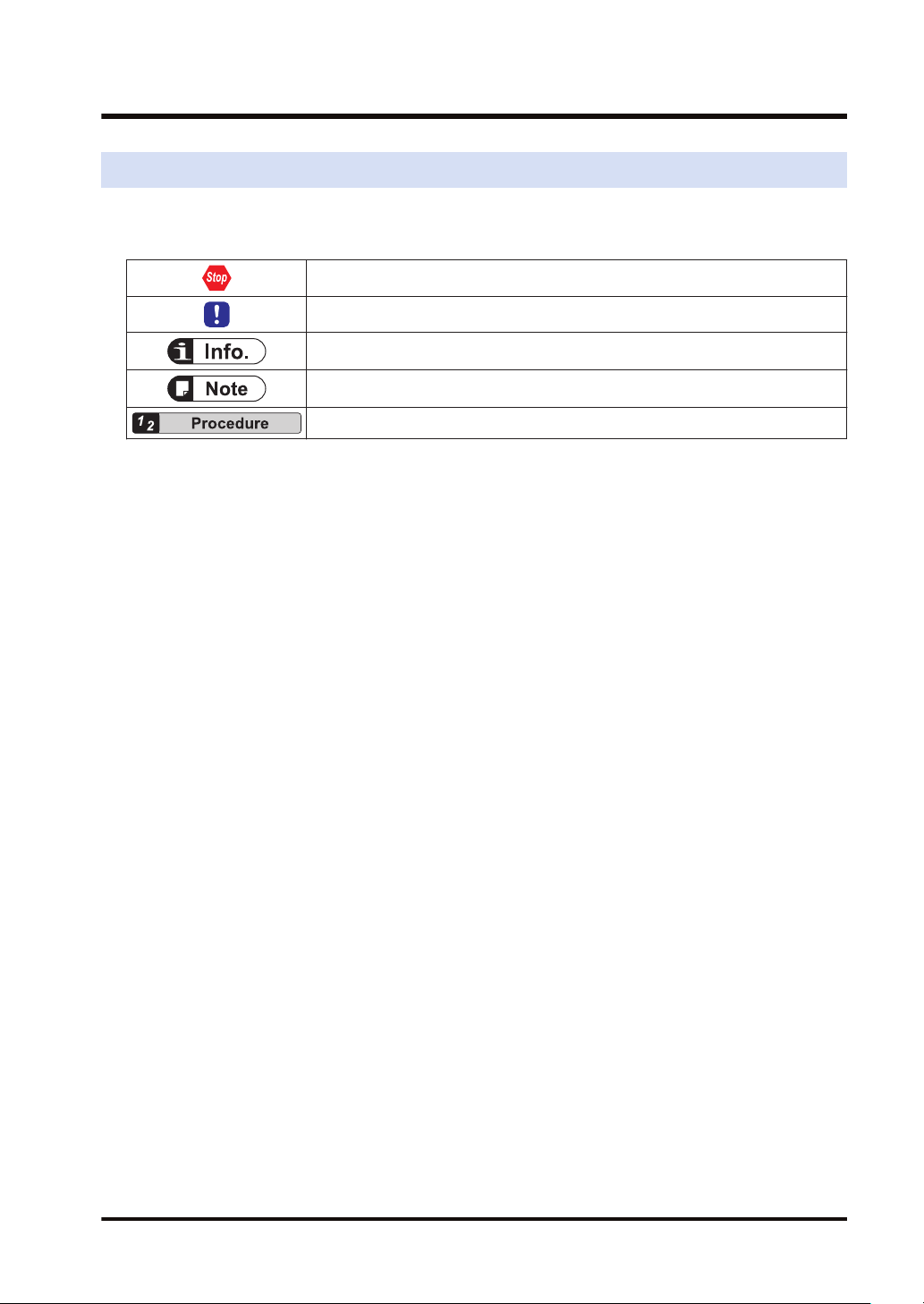
■
In this manual, the following symbols are used to indicate safety information that
must be observed.
Indicates an action that is prohibited or a matter that requires caution.
Indicates an action that must be taken.
Indicates supplemental information.
Indicates details about the subject in question or information useful to remember.
Indicates operation procedures.
■
Handling precautions
Specifications
● This product has been developed / produced for industrial use only.
● This product (controller and sensor head receiver) uses an EEPROM.
The EEPROM has a service life of one million setting operations.
● Do not use this product outside the range of the specifications. Risk of an accident and
product damage.
There is also a risk of a noticeable reduction of service life.
Power supply
● Verify that the supply voltage fluctuations are within the rating.
● If power is supplied from a commercial switching regulator, ensure that the frame ground
(F.G.) terminal of the power supply is connected to an actual ground.
● Do not use during the initial transient time after the power supply is switched ON.
● To ensure performance, use the product at least 30 minutes (warm-up time) after the power
is turned ON.
Wiring
● Make sure that the power is OFF before performing wiring or connection work for the
controller.
● Note that there is a risk of damage or burning if the load is short-circuited or incorrectly
wired.
● After wiring is completed, check the wiring carefully before turning ON the power.
● Do not wire the controller in parallel with a high-voltage line or power line or use the same
conduit as these lines. Doing so may result in malfunctioning due to induction.
● Do not apply stress such as excessive bending or pulling to the extracted part of a cable,
● When connecting the sensor head connection cable to this product, do not apply force to
the product.
Usage environment
● This product is suitable for indoor use only.
● The light emitting and receiving surfaces of the sensor head must be free of water, oil,
fingerprints, and other substances that refract light as well as dust, grit, and other objects
that intercept light.
WUME-HGT-6 1-3

1.2 Handling Precautions
If stains or dirt become attached to the sensor head surfaces, wipe them with a lint-free soft
cloth or lens cleaning paper. If the surfaces are very dirty, wipe off dirt using a cotton swab
(or similar material) moistened with absolute alcohol.
● Do not allow ambient light such as sunlight to directly hit the light receiving section of the
sensor head. In particular, if precision is required, use this product by mounting a douser (or
similar material) on the sensor head.
● When a measured object with a strong specular reflection component (such as glass or
specular reflector) is detected, it may not be detected correctly due to the influences of light
reflected from the measured object. In such a case, install a pair of emitter and receiver at a
certain angle so that reflected light does not hit the emitter or receiver. After adjusting the
angle, always check the beam axis. After checking the beam axis, if the beam axis is
aligned, register the reference waveform. If the beam axis is misaligned, readjust the beam
axis, and register the reference waveform.
● Avoid using this product in environments where condensation occurs due to sudden
temperature change.
● Avoid dust, dirt, and steam.
● Avoid using the product in atmospheres that contain corrosive or other harmful gases.
● Ensure that the product does not come into contact with organic solvents such as thinner.
● Ensure that the product does not come into contact with strong acid or alkaline.
● Ensure that the product does not come into contact with oil or grease.
● This product cannot be used in an environment that contains flammable or explosive gases.
● Performance may not be satisfactory in a strong electromagnetic field.
● Do not use this product in locations subject to severe vibration or shock.
● This product is a precision device. Do not drop or otherwise subject to shock. Risk of
product damage.
● Take care not to touch any terminals in the connector or allow foreign objects to enter the
connector.
● The sensor head is watertight, but the connectors are not structurally resistant to dust,
water or corrosion. Therefore, the HG-T series cannot be submerged in water or placed
under falling water for measurement operation. Pay attention to the environment where the
product is used.
Other matters
● Never attempt to disassemble, repair, or modify the product.
● When the product becomes unusable or unneeded, dispose the product appropriately as
industrial waste.
1-4 WUME-HGT-6

1.3 Laser Safety Standards
1.3 Laser Safety Standards
1.3.1 IEC / JIS / GB
To prevent laser products from affecting their users, IEC, JIS, and GB have the following
respective standards:
IEC: IEC 60825-1-2014
JIS: JIS C 6802-2014
GB: GB 7247.1-2012
These standards classify laser products into classes according to the danger level of laser, and
prescribe safety and preventive measures that should be implemented for each class.
This product belongs to "Class 1 laser product" according to JIS C 6802-2014 "Safety of Laser
Products".
Explanation of danger level
Classificatio
n
Class 1 This class of laser beams is safe when the operating state of the product is rightly predictable.
Class 1M
Class 2
Class 2M
Class 3R
Class 3B Direct intrabeam viewing is always dangerous.
Class 4
■
Warning label
This class of laser beams is safe when the operating state of the product is rightly predictable,
but direct intrabeam viewing by optical means can be dangerous.
This class of laser beams is visible light and low output. Normally, eyes are protected by
aversion reaction such as blinking.
This class of laser beams is visible light and low output. Normally, eyes are protected by
aversion reaction such as blinking, but direct intrabeam viewing by optical means can be
dangerous.
Direct intrabeam viewing is potentially dangerous, but the level of risk is lower than Class 3B
laser.
This class of laser beams is high output. It has the ability to cause dangerous diffuse reflection.
Such laser beams cause skin disorders and have the risk of fire occurrence.
Overview of danger evaluation
On the emitter side
WUME-HGT-6 1-5
1.3 Laser Safety Standards
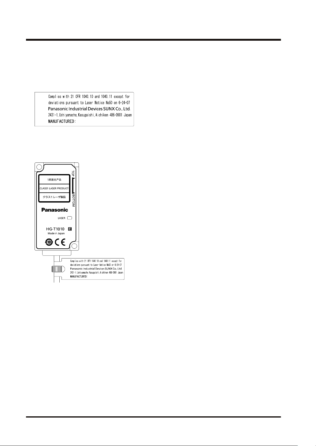
1.3.2 FDA
■
Exporting to the USA
If this product is incorporated into facilities or equipment to be exported to the USA, it is subject
to the laser regulations of the U.S. Food and Drug Administration (FDA). To prevent laser
products from affecting their users, PART1040 (Performance Standards for Light-Emitting
Products) was established as one of the FDA regulations. These standards classify laser
products into classes according to the danger level of laser and prescribe safety and preventive
measures that should be implemented for each class.
This product complies with the FDA regulations (21 CFR 1040. 10 and 1040.11) in accordance
with FDA Laser Notice No. 50. (Class 1 laser product)
■
FDA regulations
(Note 1)
Requirements
Performance (for all laser products)
Protective housings [1040.10(f)(1)]
Safety interlock
[1040.10(f)(2)]
Location of controls [1040.10(f)(7)] N/A R R R R R
Viewing optics [1040.10(f)(8)] R R R R R R
Scanning safeguard [1040.10(f)(9)] R R R R R R
Performance (for laser systems)
Remote interlock connector
[1040.10(f)(3)]
Key control [1040.10(f)(4)] N/A N/A N/A N/A R R
Ⅰ Ⅱa Ⅱ Ⅲa Ⅲb Ⅳ
(Note 2)R(Note 2)R(Note 2)R(Note 2)R(Note 2)R(Note 2)
R
(Note 3)
R
(Note 4)
N/A N/A N/A N/A R R
(Note 3)
R
(Note 4)
Class
(Note 3)
R
(Note 4)
(Note 3)
R
(Note 4)
(Note 3)
R
(Note 4)
(Note 3)
R
(Note 4)
1-6 WUME-HGT-6

1.3 Laser Safety Standards
(Note 1)
Requirements
Ⅰ Ⅱa Ⅱ Ⅲa Ⅲb Ⅳ
Emission indicator [1040.10(f)(5)] N/A N/A R R
Beam attenuator [1040.10(f)(6)] N/A N/A R R R R
Manual reset [1040.10(f)(10)] N/A N/A N/A N/A N/A
Performance (for special-purpose products)
Medical use [1040.11(a)] S S S
Surveying, leveling, and alignment
S S S S NP NP
[1040.11(b)]
Demonstration [1040.11(c)] S S S S
Labeling (for all laser products)
Certification and identification
R R R R R R
[1010.2,3]
Protective housings [1040.10(g)(6),
(7)]
D
(Note 5)R(Note 5)R(Note 5)R(Note 5)R(Note 5)
R
Openings [1040.10(g)(4)] N/A N/A N/A N/A N/A N/A
Class warning [1040.10(g)(1), (2),
(3)]
N/A
(Note 6)R(Note 7)R(Note 9)R(Note 12)R(Note 12)
R
Information (for all laser products)
User information [1040.10(h)(1)] R R R R R R
Product literature [1040.10(h)(2)(i)] N/A R R R R R
Service information [1040.10(h)(2)
R R R R R R
(ii)]
Class
(Note 10)R(Note 10)
R
(Note 8)S(Note 8)S(Note 8)
S
(Note 11)S(Note 11)
S
(Note 13)
R
R : Required
N/A : Not applicable
S : Same requirements as for other products of the class
NP : Not permitted
D : Depends on the internal radiation level
(Note 1) Based on the maximum level of exposure to radiation during operation
(Note 2) Required wherever and whenever if exposure to laser radiation exceeding the limit of Class 1 is not
necessary to fulfill the functions of the product
(Note 3) Required for protective housings that are opened during operation or maintenance if radiation
exposure that occurs when the housing is opened is not always necessary
(Note 4) Requirements for interlock differ according to the class of internal radiation.
(Note 5) Wording differs according to the level and wavelength of laser radiation inside the protective housing.
(Note 6) A label that indicates a warning statement
(Note 7) CAUTION logo
(Note 8) A means is required to measure the level of laser radiation for the purpose of human body irradiation.
(Note 9)
CAUTION is used when the radiation level is 2.5 mWcm-2 or lower, and DANGER is used when the
radiation level is higher than 2.5 mWcm-2.
(Note 10) Time lag is required between reading and emission.
WUME-HGT-6 1-7
1.3 Laser Safety Standards
(Note 11) Exception handling is required for laser products and light show for demonstration of Class IIIb or IV.
(Note 12) DANGER logo
(Note 13) Required since August 20, 1986
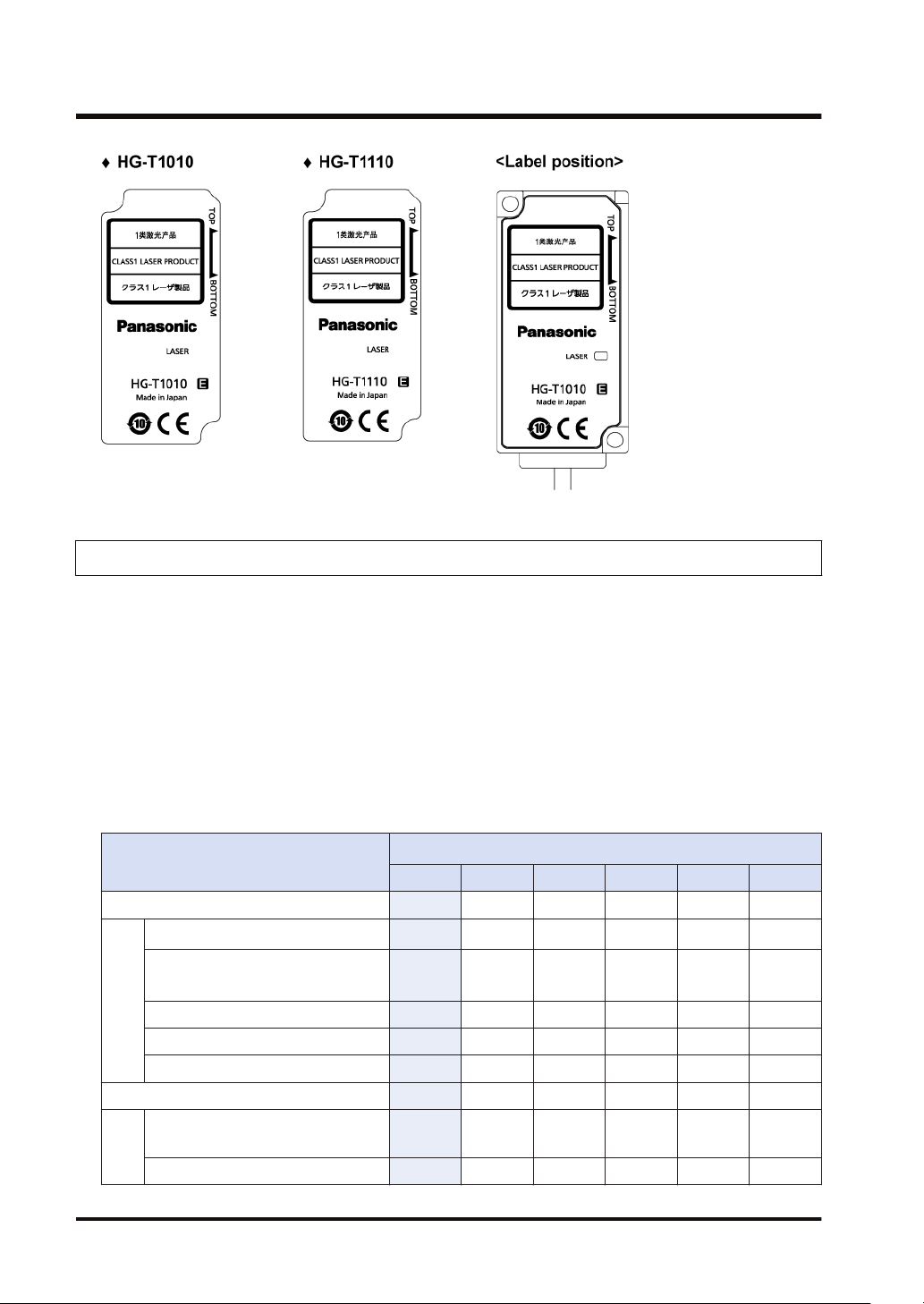
■
Recognition / identification label
■
Label position
Emitter
● Common to HG-T1010 and HG-T1110
1-8 WUME-HGT-6

1.4 Terminology
1.4 Terminology
Term Description
Controller - Master unit A controller that can be used on a standalone basis
Controller - Slave unit A controller that is used by connecting to a master unit
Sensor head - Emitter A sensor head emitter that is used by connecting to a controller
Sensor head Receiver
Sensor head
connection
cable
Side view attachment An attachment that is used to refract laser beams from the sensor head at 90 degrees
End plate
Communication unit
(Note 1) For details on communication units, refer to the user's manual for each communication unit.
A sensor head receiver that is used by connecting to a controller
A cable that is used to connect a sensor head and controller
A plate that is used to secure both ends of controllers to prevent the connectors from
coming off and causing a communication failure when controllers are connected
An interface unit that enables measurement data and other data of connected
controllers to be monitored.
(Note 1)
WUME-HGT-6 1-9
1.5 Contents of Package
1.5 Contents of Package
The following accessories are included in the product package. Before using the product, make
sure that no items are missing.
Controller
HG-TC101 / Master unit of high-performance NPN
output type
HG-TC101-P / Master unit of high-performance PNP
output type
● Controller: 1 pc.
HG-TC111 / Slave unit of high-performance NPN
output type
HG-TC111-P / Slave unit of high-performance PNP
output type
● Controller: 1 pc.
● Instruction Manual
(English / Japanese, Chinese / Korean): 1 pc. each
● General Information for Safety, Compliance, and
Instructions (23 languages): 1 pc.
HG-TC113 / Slave unit of wire-saving type
● Controller: 1 pc.
● Instruction manual
(English / Japanese, Chinese / Korean): 1 pc. each
● General Information for Safety, Compliance, and
Instructions (23 languages): 1 pc.
Sensor head
HG-T1010 / Measurement width 10 mm, standard type
● Sensor head (emitter and receiver): 1 set
● Instruction manual
(English / Japanese, Chinese / Korean): 1 pc. each
● General Information for Safety, Compliance, and
Instructions (23 languages): 1 pc.
HG-T1110 / Measurement width10 mm, slim type
● Sensor head (emitter and receiver): 1 set
● Instruction manual
(English / Japanese, Chinese / Korean): 1 pc. each
● Instruction manual
(English / Japanese, Chinese / Korean): 1 pc. each
1-10 WUME-HGT-6
1.5 Contents of Package
Sensor head
● General Information for Safety, Compliance, and
Instructions (23 languages): 1 pc.
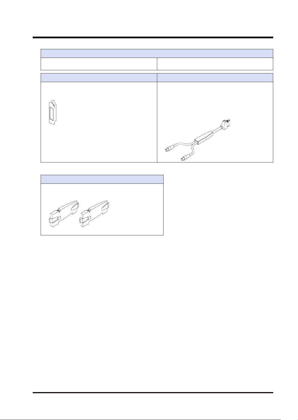
Side view attachment Sensor head connection cable
HG-TSV10 / Side view attachment
● Attachment: 1 pc.
(Note 1)
● M2 screw with washer (length: 4 mm): 2 pcs.
(Note 1) HG-TSV10 is sold by one unit. Two units are required for a pair of emitter and receiver.
End plate
MS-DIN-E / End plate
● Plate: Set of 2 pcs.
● General Information for Safety, Compliance, and
Instructions (23 languages): 1 pc.
CN-HT-C2 / Cable length 2 m
CN-HT-C5 / Cable length 5 m
CN-HT-C10 / Cable length 10 m
CN-HT-C20 / Cable length 20 m
● Connection cable: 1 pc.
● Instruction manual
WUME-HGT-6 1-11
1.6 Product Version and Functions
1.6 Product Version and Functions
The following functions are added to the HG-TC□ series controllers and HG-T□ series sensor
heads manufactured in November 2020 onwards.
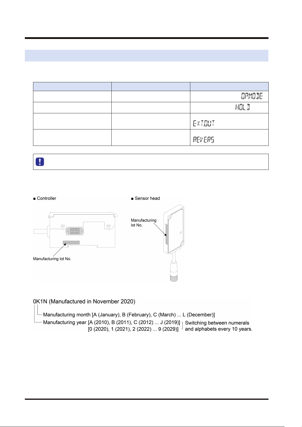
Added function Description Remarks
Assigned edge detection mode Operation mode
Tab cancellation function Hold setting
Hold state output External output "7.2.4 External Outputs
Measured value reversal selection
function
● The controllers and sensor heads manufactured in October 2020 or earlier do not support
the above functions. Please note this point.
■
<How to check manufacturing year and month>
Measured value reversal "7.2.13 Reverse of Measured Value
Check the manufacturing lot No. shown in the following figure.
"6.3.1 Operation Mode ( )"
"7.2.1 Hold Settings ( )"
(
( )"
)"
■
<How to interpret the manufacturing lot No.>
1-12 WUME-HGT-6

2 System Configuration
2.1 System Configuration..........................................................................2-2
2.2 Description of Parts.............................................................................2-3
2.2.1 Controller ......................................................................................... 2-3
2.2.2 Sensor head..................................................................................... 2-5
2.2.3 Sensor Head Connection Cable ...................................................... 2-6
2.2.4 Side View Attachment...................................................................... 2-6
WUME-HGT-6 2-1
2.1 System Configuration
2.1 System Configuration
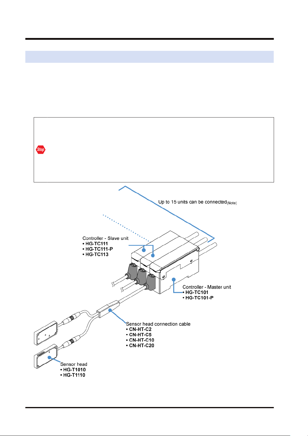
The HG-T series consists of controllers, sensor head connection cables, and sensor heads.
For the controllers, master units (two types) and slave units (three types) are available. Up to 15
slave units can be connected to one master unit. For the sensor heads, two types are available.
For the sensor head connection cables, four types are available.
Connecting a communication unit to the end of the connection enables information to be
checked from outside. (Note 1)
● Always shut OFF the power before connecting or disconnecting a slave unit or
communication unit to / from the master unit. If you connect or disconnect a unit with the
power ON, the controller may become damaged.
● Insert the male connector all the way into the female connector. If the connectors are not
completely connected, the controller may become damaged.
● To connect units, always mount them on a DIN rail. To do so, mount end plates MS-DIN-E
(optional) so as to enclose the connected units at both ends.
● When connecting slave units to the master unit, connect only NPN output type units or
only PNP output type units. Dissimilar output types cannot be connected together.
(Note 1) When a communication unit is connected, up to 14 slave units can be connected.
2-2 WUME-HGT-6
2.2 Description of Parts
2.2 Description of Parts
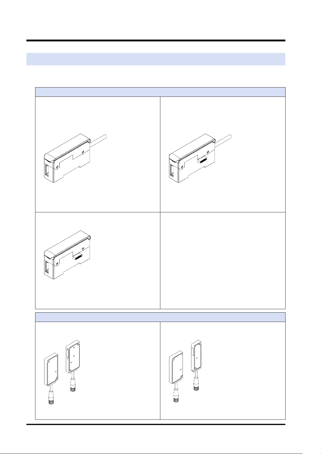
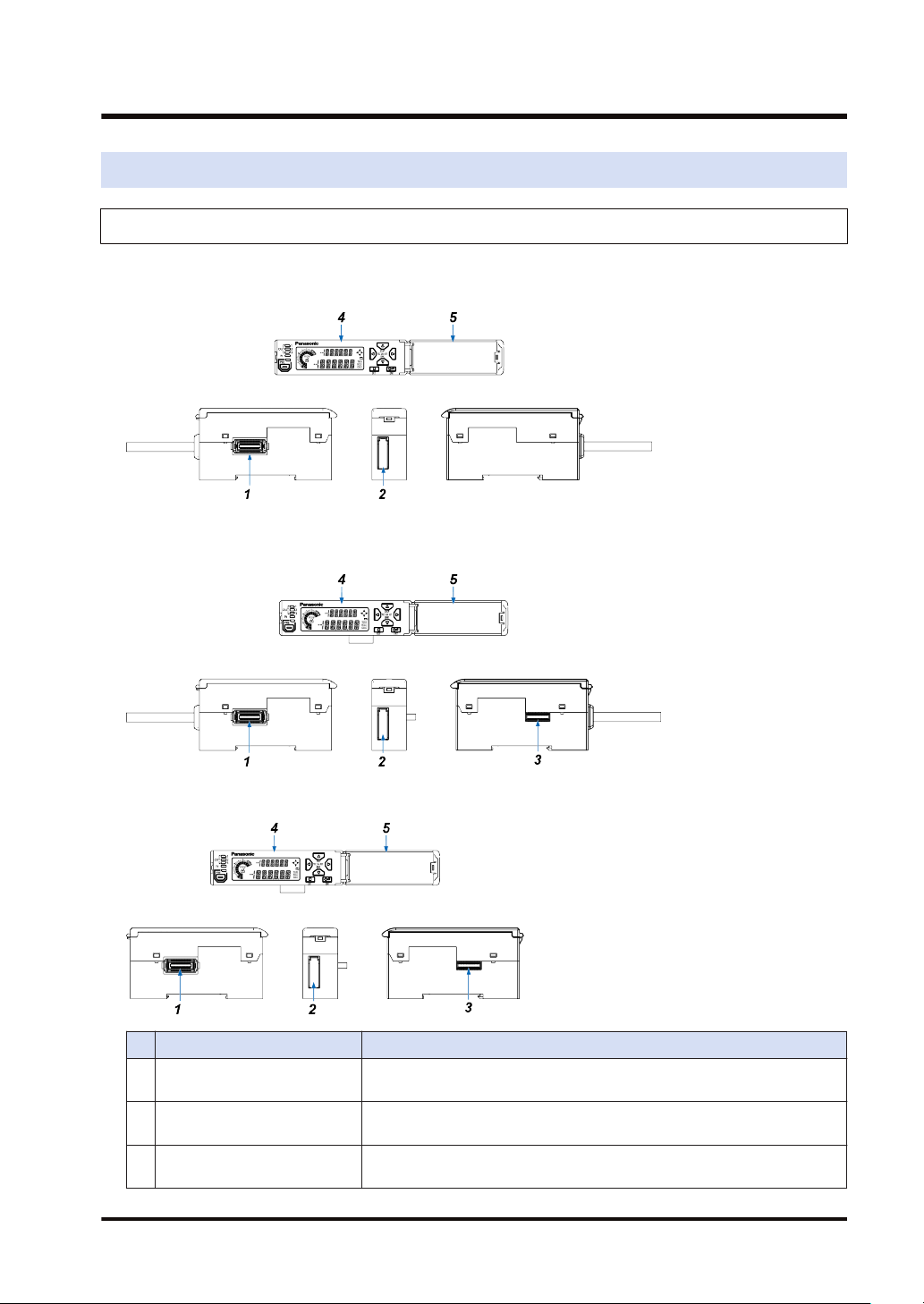
2.2.1 Controller
HG-TC101 / Master unit of high-performance NPN output type, HG-TC101-P / Master
unit of high-performance PNP output type
HG-TC111 / Slave unit of high-performance NPN output type, HG-TC111-P / Slave unit
of high-performance PNP output type
HG-TC113 / Slave unit of wire-saving type
Name Function
1 Female connector
Sensor head connection cable
2
connector
Male connector (for slave unit
3
only)
WUME-HGT-6 2-3
For connection to a slave unit. Remove the connector cover before
connecting to a slave unit.
Connects the sensor head connection cable.
For connection to a master unit or slave unit.
2.2 Description of Parts
Name Function
Digital display section /
4
operation unit
Digital display section /
5
operation unit cover
■
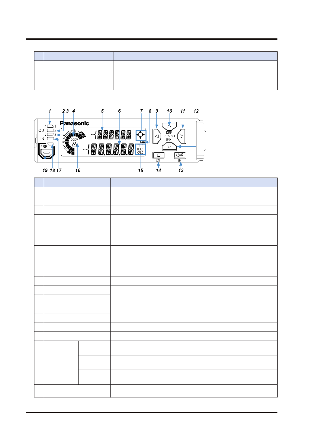
Display unit / operation unit
Name Function
1 Output 1 indicator (Orange) Lights up when output 1 is ON.
2 Output 2 indicator (Orange) Lights up when output 2 is ON.
3 Output 3 indicator (Orange) Lights up when output 3 is ON.
4 Circle meter (Orange, green)
Digital display section / SUB
5
(Green)
Digital display section / MAIN
6
(White)
Guide mark / arrow keys
7
(White)
8 Guide mark / Enter (White) Lights up when the ENTER key is enabled during each setting operation.
9 LEFT key
10 UP key
11 RIGHT key
12 DOWN key
13 ENTER key Used to select setting items and apply settings when configuring settings.
14 EXIT key Used to exit a setting item or cancel a setting when configuring settings.
TRIG
(White)
15 Status mark
16 Copy checkmark (Orange)
HOLD
(White)
CALC
(White)
For checking measured values and perform setting operation. For details,
refer to the following page.
Protects the display unit and operation unit. Keep the cover closed when
the display unit / operation unit is not used.
● Shows increases or decreases of the judgment value by meter display.
● Shows the level and item sequence of setting work by navigation display.
Shows the setting item and the item set using display switching mode.
Shows the measured value, judgment value, and setting.
Lights up when each key (LEFT / RIGHT / UP / DOWN) is enabled during
each setting operation.
Used to change setting items and settings when configuring settings, and to
move through set value digits.
Lights up while the trigger input (external input) is ON.
Lights up while the judgment value is held.
Lights up when calculation mode is set with a slave unit connected.
"COPY" lights up for a setting item that can be copied to a slave unit when a
master unit is set up. In this case, if the setting item is selected as a copy
2-4 WUME-HGT-6
Name Function
target, the checkmark will light up and executing copy will perform copy
processing.
17 Input indicator (White) Lights up when external input 1, 2, or 3 is ON.
18 Preset indicator (Green) Lights up when the preset function is used.
19 Preset key Used to set and cancel the preset function.
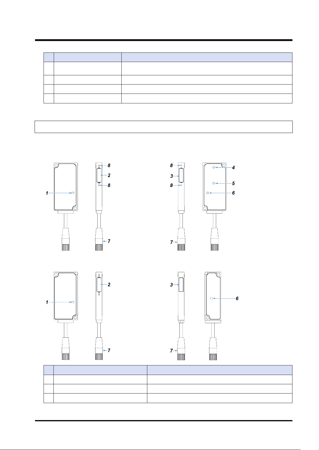
2.2.2 Sensor head
HG-T1010
Emitter Receiver
2.2 Description of Parts
HG-T1110
Emitter Receiver
Name Function
1 Laser radiation indicator (Green) Lights up when laser beams are emitted.
2 Light emitting surface The surface that emits laser beams
3 Light receiving surface The surface that receives laser beams
WUME-HGT-6 2-5
2.2 Description of Parts
Name Function
Beam axis adjustment indicator / TOP
4
part (Orange / Green)
Beam axis adjustment indicator /
5
BOTTOM part (Orange / Green)
Judgment output indicator (Orange /
6
Green)
7 Sensor head connection cable connector Connects the sensor head connection cable.
Female thread for mounting side view
8
attachment
(Note 1) The HG-T1110 is not equipped with the beam axis adjustment indicators (TOP / BOTTOM part).
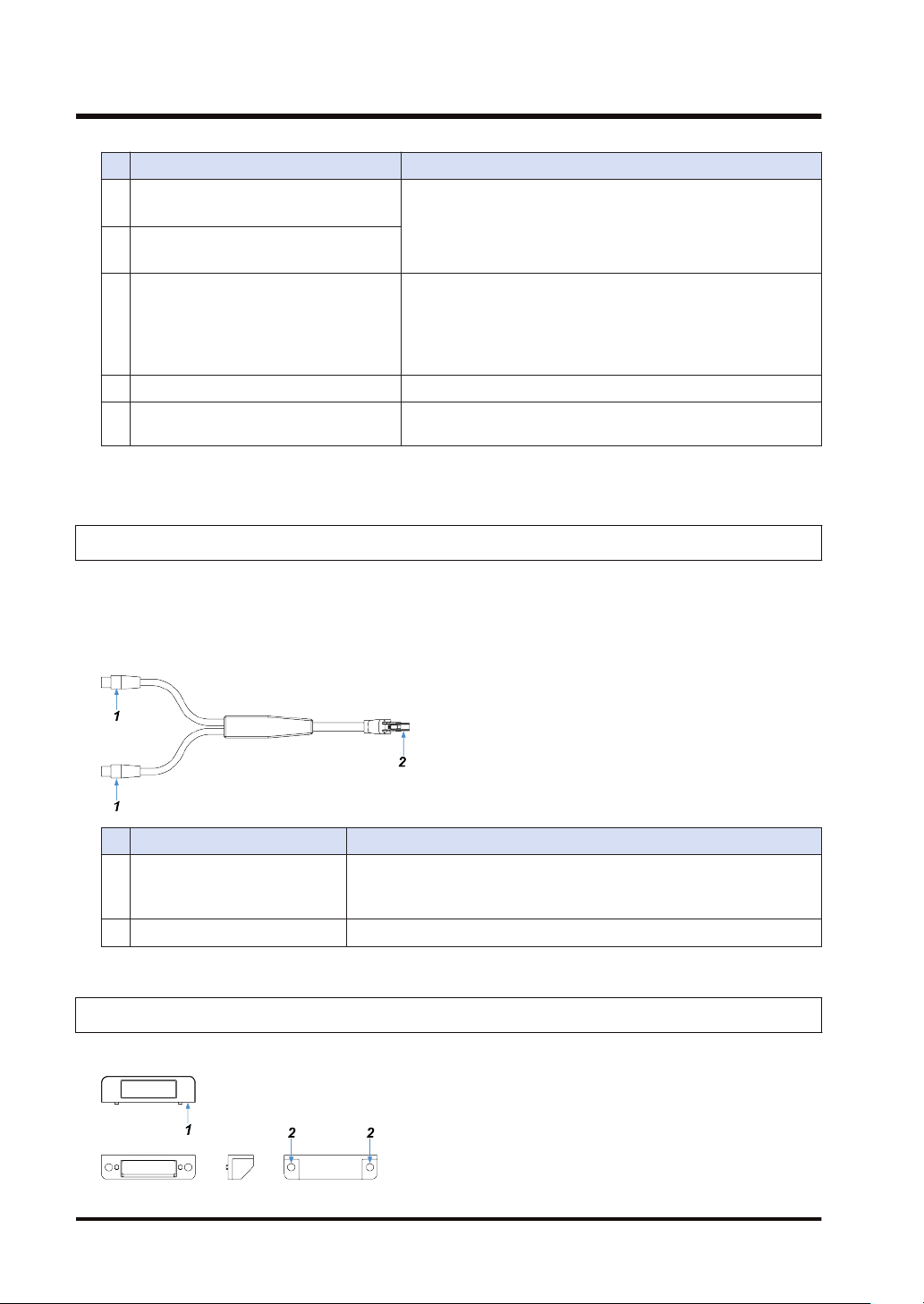
2.2.3 Sensor Head Connection Cable
CN-HT-C2 / Cable length 2 m
CN-HT-C5 / Cable length 5 m
CN-HT-C10 / Cable length 10 m
CN-HT-C20 / Cable length 20 m
(Note 1)
(Note 1)
Indicates the beam axis adjustment state as light color (green or
orange) and lighting state (lit, flashing, or unlit). (Only when the
beam axis adjustment function is used)
When controller judgment value is within the threshold range:
Lights green.
When controller judgment value is outside the threshold range:
Lights orange.
When the beam axis adjustment function is used: OFF
Connects the side view attachment and sensor head using an
M2 screw with washer (length: 4 mm).
Name Function
Connects to the sensor head cable connector on the sensor head.
1 Sensor head connector
There is no difference between the connectors on the emitter side and on
the receiver side.
2 Controller connector Connects to the sensor head cable connector on the controller.
2.2.4 Side View Attachment
HG-TSV10
2-6 WUME-HGT-6

Name Function
1 Sensor head mounting surface
2 Sensor head mounting hole
2.2 Description of Parts
Mounts the side view attachment on the light emitting and receiving
surfaces of the sensor head
Connects the side view attachment and sensor head using an M2 screw
with washer (length: 4 mm).
WUME-HGT-6 2-7

(MEMO)
2-8 WUME-HGT-6

3 Overview of HG-T Series
3.1 Principle of Measurement ...................................................................3-2
3.2 Role of Controllers ..............................................................................3-3
3.3 Using Connected Controllers..............................................................3-4
WUME-HGT-6 3-1
3.1 Principle of Measurement
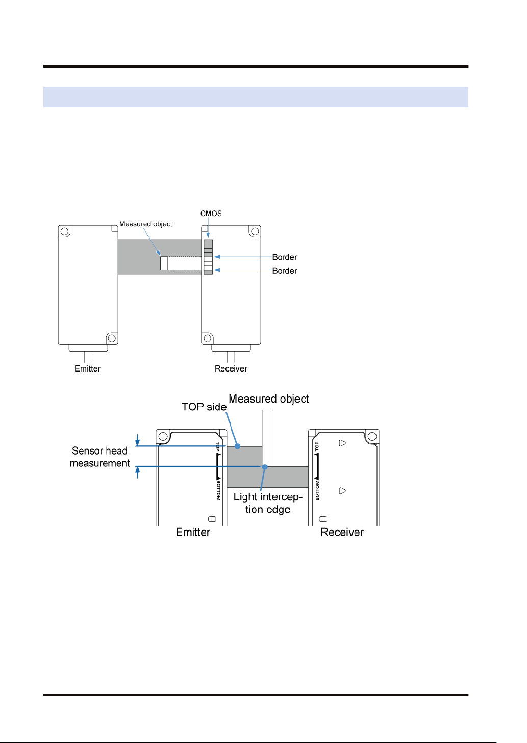
3.1 Principle of Measurement
The sensor head emits belt-shaped laser beams from its emitter and receives them with the
light receiving element (CMOS) of its receiver. If a measured object is inserted between the
emitter and receiver of the sensor head, the bright section (light entry section) that receives
laser beams and the dark section (light interception section) that is the shade of the measured
object are projected on to the CMOS.
The difference in the amount of received light between each pixel of the CMOS is used to
detect position information about the border between the light entry section and the light
interception section and measure the object.
● The edge position of the measured object can be measured.
3-2 WUME-HGT-6
 Loading...