

Panasonic HG-S User Manual

Contact-Type Digital Displacement Sensor
HG-S Series
User's Manual
WUME-HGS-7
2020.10
panasonic.net/id/pidsx/global

(MEMO)
WUME-HGS-72

Thank you for purchasing an contact-type digital displacement sensor
HG-S
series.
Before using this product, read and understand this User's Manual. Use the product correctly
and in the optimum manner.
Keep this manual in a safe location for reference whenever necessary.
Please note
1) Unauthorized reproduction of part or all of this manual is prohibited.
2) The contents of this manual are subject to change without notice.
3) This manual has undergone strict quality control procedures; however, in the event that you
discover any problems or points of concern, please contact your local dealer.
WUME-HGS-7 3

Contents
Chapter 1 INTRODUCTION ····························································· 1-1
1-1 Safety Cautions
1-2 Safety Information
······························································
····························································
Chapter 2 BEFORE USING THIS PRODUCT ······································ 2-1
2-1 Contents of Package
2-2 System Conguration
2-3 Description of Parts
2-3-1 Controller············································································· 2-7
2-3-2 Sensor Head (Regular Type) ··················································· 2-9
2-3-3 Sensor Head (Air-Driven Type) ················································· 2-9
2-3-4 Sensor Head Connection Cable ··············································· 2-10
·························································
························································
··························································
Chapter 3 INSTALLATION AND CONNECTIONS ································· 3-1
3-1 Mounting the Controller
3-1-1 Mounting on a DIN Rail ·························································· 3-2
3-1-2 Removing from a DIN Rail ······················································· 3-2
3-2 Attaching the Sensor Head
3-3 Wiring the Controller Connector on the Sensor Head Connection Cable 3-5
3-3-1 Disassembly Procedure ·························································· 3-5
3-3-2 Wiring Procedure ·································································· 3-5
3-4 Connecting the Controller and Sensor Head
3-4-1 Attaching the Sensor Head and Sensor Head Connection Cable ····· 3-7
3-4-2 Removing the Sensor Head and Sensor Head Connection Cable ···· 3-8
3-4-3 Connecting the Air Tube (Air-Driven Type Only) ··························· 3-9
3-4-4 Disconnecting the Air Tube (Air-Driven Type Only) ·······················3-9
3-4-5 Air Circuit (Recommended) (Air-Driven Type Only) ······················· 3-10
3-4-6 Attaching the Controller and Sensor Head Connection Cable ·········3-11
3-4-7 Removing the Controller and Sensor Head Connection Cable ········ 3-11
3-5 Connecting Controllers
3-5-1 Connection Method ······························································· 3-13
3-5-2 Removal Method ··································································· 3-15
3-6 Connection Diagrams and I/O Circuit Diagrams
3-6-1 Connection Diagrams ····························································· 3-16
3-6-2 I/O Circuit Diagrams······························································· 3-18
······················································
··················································
······························
·······················································
···························
1-2
1-2
2-2
2-6
2-7
3-2
3-3
3-7
3-12
3-16
Chapter 4 BASIC OPERATION ························································ 4-1
4-1 Explanation of Basic Operation
4-1-1 From Power ON to Mode Selection ··········································· 4-2
4-1-2 Operation Keys and Display ···················································· 4-3
4-2 Explanation of Modes
4-2-1 Display Switching Mode ·························································· 4-5
4-2-2 Presets ··············································································· 4-8
4-2-3 Teaching Mode ····································································· 4-11
4-2-4 Bank Mode ·········································································· 4-20
4-2-5 Key Lock ············································································· 4-24
·······················································
·············································
WUME-HGS-74
4-2
4-5
4-3 Self-monitoring Function
4-3-1 Using the Self-monitoring Function ··········································· 4-26
4-3-2 Statuses and Measures ·························································· 4-27
·····················································
4-26
Chapter 5 FUNCTION SETTINGS ···················································· 5-1
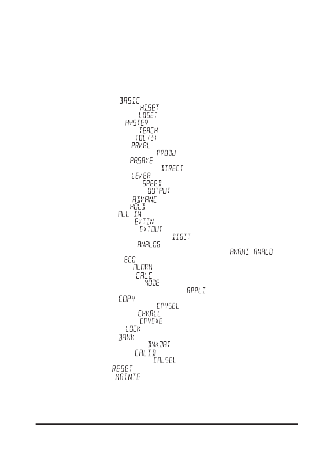
5-1 Overview of Setting Menu
5-1-1 Menu Structure ····································································· 5-4
5-1-2 Data Flow ············································································ 5-6
5-1-3 Setting Items and Default Values ·············································· 5-7
5-2 Basic Settings ( )
5-2-1 HIGH Set Value ( ) ························································· 5-11
5-2-2 LOW Set Value ( ) ························································· 5-12
5-2-3 Hysteresis ( ) ······························································ 5-13
5-2-4 Teaching Types ( ) ························································· 5-15
5-2-5 Tolerance <±> ( ) ·························································· 5-17
5-2-6 Preset Value ( ) ····························································· 5-18
5-2-7 Preset Data Selection ( ) ················································· 5-19
5-2-8 Preset Save ( ) ···························································· 5-20
5-2-9 Measurement Direction ( ) ·············································5-21
5-2-10 Lever Ratio ( ) ····························································· 5-23
5-2-11 Response Time ( ) ························································ 5-24
5-2-12 Output Operation ( ) ··················································· 5-26
5-3 Advanced Settings ( )
5-3-1 Hold Setting ( ) ······························································· 5-28
5-3-2 Input All ( ) (Master Unit Only) ········································5-53
5-3-3 External Input ( ) ··························································· 5-55
5-3-4 External Output ( ) ······················································· 5-57
5-3-5 Number of Digits Displayed ( ) ·········································· 5-60
5-3-6 Analog Scaling ( ) ························································ 5-61
5-3-7
Scaling Upper Limit Value / Scaling Lower Limit Value
5-3-8 Eco Mode ( ) ···································································· 5-66
5-3-9 Alarm Setting ( ) ···························································· 5-67
5-4 Calculation Settings ( ) (Master Unit Only)
5-4-1 Calculation Mode ( ) ························································· 5-77
5-4-2 Calculation Application Selection ( ) ·································· 5-78
5-5 Copy Settings ( )
5-5-1 Copy select individual ( ) (Master Unit Only) ······················ 5-87
5-5-2 Copy Select All ( ) (Master Unit Only) ······························· 5-89
5-5-3 Copy Execution ( ) (Master Unit Only) ······························ 5-90
5-5-4 Copy Lock ( ) (Slave Units Only) ········································· 5-91
5-6 Bank Settings ( )
5-6-1 Bank Save Setting ( ) ··················································· 5-92
5-7 Calibration Settings ( )
5-7-1 Calibration Selection ( ) ················································ 5-94
5-8 Initialization ( )
5-9 Maintenance ( )
···················································
······················································
···············································
( / ) ·· 5-63
···························
························································
·························································
················································
·························································
······················································
5-4
5-10
5-27
5-76
5-85
5-92
5-94
5-98
5-100
Chapter 6 SPECIFICATIONS ··························································· 6-1
6-1 Specications
6-2 Dimensions
WUME-HGS-7 5
·································································
····································································
6-2
6-8

Chapter 7 Appendix ······································································· 7-1
7-1 Maintenance and Inspection
7-1-1 Maintenance Cautions ···························································· 7-2
7-1-2 Main Inspection Items ···························································· 7-2
7-2 Replacing the Probe
7-3 Replacing the Rubber Bellows (Regular Type Only)
7-4 Replacing the Seal Cap (Air-Driven Type Only)
7-4-1 How to Remove the Seal Cap ·················································· 7-6
7-4-2 How to Mount the Seal Cap ····················································· 7-6
7-5 Error Messages
7-6 Troubleshooting
··························································
·······························································
·······························································
················································
······················
···························
7-2
7-3
7-4
7-6
7-7
7-8
WUME-HGS-76

Chapter 1 INTRODUCTION
1-1 Safety Cautions ······································································· 1-2
1-2 Safety Information ····································································· 1-2
1-1
INTRODUCTION
1-1 Safety Cautions
This section explains important rules that must be observed to prevent human injury and property damage.
■ The hazards that may occur if the product is used incorrectly are described and classied by
level of harm.
WARNING
CAUTION
■ The following symbols are used to indicate safety information that must be observed.
Indicates an action that is prohibited.
Indicates an action that must be taken.
Indicates a matter that requires caution.
<Reference>
Indicates supplemental information.
Always observe
Risk of death or serious injury.
Risk of minor injury or property damage.
1-2 Safety Information
WARNING
● Never use this product as a sensing device for personnel protection.
● When using sensing devices for personnel protection, use products that meet the laws and stan-
dards for personnel protection that apply in each region or country, such as OSHA, ANSI and IEC.
CAUTION
● For the controller DC power supply, only use a power supply that is isolated by means of an isola-
tion transformer or otherwise.
● Risk of short-circuiting and damage to the controller or power supply if a transformer such as an
auto transformer is used. Risk of short-circuiting and damage to the controller or power supply if incorrectly mounted or connected.
● The controller
used with other than the special sensor head option, the specications will not be met and product
malfunctioning or damage may occur.
HG-SC
series is designed to be used with the special sensor head
HG-S
WUME-HGS-71-2
series. If

INTRODUCTION
Specications
● This device has been developed / produced for industrial use only.
● This product uses an EEPROM. The EEPROM has a service life of one million setting operations.
● Do not use this product outside the range of the specications. Risk of an accident and prod-
uct damage. There is also a risk of a noticeable reduction of service life.
● Deviations may occur in the judgment value at the bottom dead point. Do not use the bottom
dead point as a standard.
Power
● Verify that the supply voltage uctuations are within the rating.
● If power is supplied from a commercial switching regulator, ensure that the frame ground
(F.G.) terminal of the power supply is connected to an actual ground.
● Do not use during the initial transient time after the power supply is switched ON.
Wiring and Installation
● Make sure that the power supply is OFF while performing wiring or expansion work on the
controller.
● Take care that short-circuit of the load or wrong wiring may burn or damage the product.
● After you have completed wiring work, check the wiring carefully before switching on the power.
● Do not wire in parallel with a high-voltage line or power line, or run through the same conduit.
Risk of malfunctioning due to induction.
● Do not apply stress such as excessive bending or pulling to the extracted part of a cable.
●
When attaching the sensor head connection cable to this product, do not apply force to the product.
● Only one joint (optional) can be installed to one sensor head.
● If the Low measuring force type (
and used with a roller-type probe (
HG-S1010R/HG-S1110R
HG-SS40U
, optional), the joint (optional) cannot be used.
) is mounted in a lateral position
Usage environment
● This product is suitable for indoor use only.
● Avoid dust, dirt, and steam.
● Do not use this sensor in places where it may come in contact with corrosive gas, etc.
● Ensure that the product does not come into contact with organic solvents such as thinner.
● Ensure that the product does not come into contact with strong acid or alkaline.
● Ensure that the product does not come into contact with oil or grease.
● This product cannot be used in an environment containing ammable or explosive gases.
● Performance may not be satisfactory in a strong electromagnetic eld.
●
This product is a precision device. Do not drop or otherwise subject to shock. Risk of product damage.
● Ensure that strong horizontal force is not applied to the spindle. This may cause loss of accu-
racy and decreased durability.
Handling (Regular type)
● Never remove the standard rubber bellows except for replacement. Risk of product damage
due to inltration by dust, water, or other contaminants.
● The standard rubber bellows is a consumable part. Replace it regularly as a preventive main-
tenance.The rubber bellows can deteriorate quickly depending on usage environment. If it
deteriorates, it generates cracks and other problems,causing dust and water to enter and resulting in a malfunction.
WUME-HGS-7 1-3

Handling (Air-driven type)
● Mount a pressure-reducing valve to use the product within the allowable working pressure
range. Excessive pressure may result in failure or damage.
● Do not use air containing dust, water, oil, or other foreign matter. Doing so may result in elec-
tric shock or failure. To prevent such problems, take appropriate measures such as installing
air lters or mist separators.
● Do not use air containing foreign objects (such as carbon powder or dust), water, or oil. Do-
ing so may result in electric shock or failure. To prevent such problems, take appropriate
measures such as mounting air lters or mist separators.
Other matters
● Never attempt to disassemble, repair, or modify the product.
● When the product becomes unusable or unneeded, dispose of the product appropriately as
industrial waste.
WUME-HGS-71-4

Chapter 2 BEFORE USING THIS
PRODUCT
2-1 Contents of Package ································································· 2-2
2-2 System Conguration ································································ 2-5
2-3 Description of Parts ··································································· 2-6
2-3-1 Controller············································································· 2-6
2-3-2 Sensor Head (Regular Type) ··················································· 2-8
2-3-3 Sensor Head (Air-Driven Type) ················································· 2-8
2-3-4 Sensor Head Connection Cable ··············································· 2-9
2-1
BEFORE USING THIS PRODUCT
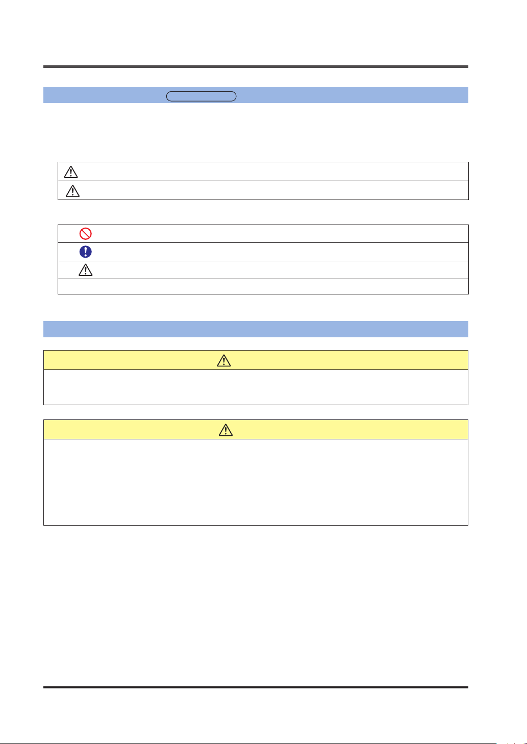
2-1 Contents of Package
The following accessories are included in the product package. Before using the product, make
sure that no items are missing.
Controller
HG-SC101 / Master unit, high-performance type
HG-SC101-P / Master unit, high-performance type
Controller: 1 pc.
●
Instruction Manual (English / Japa-
●
nese, Chinese / Korean): 2 pcs.
General Information for Safety, Compliance,
●
and Instructions (23 languages): 1 pc.
HG-SC111 / Slave unit, high-performance type
HG-SC111-P / Slave unit, high-performance type
HG-SC112 / Slave unit, standard type
HG-SC112-P / Slave unit, standard type
Controller: 1 pc.
●
Sensor head (Regular type)
HG-S1010 / General purpose, standard,
10mm type
HG-S1110 / High-performance, standard,
10mm type type
Sensor head: 1 pc. ●Nut: 1 pc.
●
Sensor head fasten-
●
ing wrench: 1 pc.
Instruction Manual (English / Japa-
●
nese, Chinese / Korean): 2 pcs.
General Information for Safety, Compliance,
●
and Instructions (23 languages): 1 pc.
HG-S1010R / General purpose, low measuring force, 10mm type type
HG-S1110R / High-performance, low
measuring force, 10mm type type
Sensor head: 1 pc. ●Nut: 1 pc.
●
Instruction Manual (English / Japa-
●
nese, Chinese / Korean): 2 pcs.
General Information for Safety, Compliance,
●
and Instructions (23 languages): 1 pc.
HG-SC113 / Slave unit, wire-saving type
Controller: 1 pc.
●
Instruction Manual (English / Japa-
●
nese, Chinese / Korean): 2 pcs.
General Information for Safety, Compliance,
●
and Instructions (23 languages): 1 pc.
Rubber bellows:
●
1 pc.
Sensor head fastening wrench: 1 pc.
●
Instruction Manual (English / Japa-
●
nese, Chinese / Korean): 2 pcs.
General Information for Safety, Compliance,
●
and Instructions (23 languages): 1 pc.
WUME-HGS-72-2
BEFORE USING THIS PRODUCT
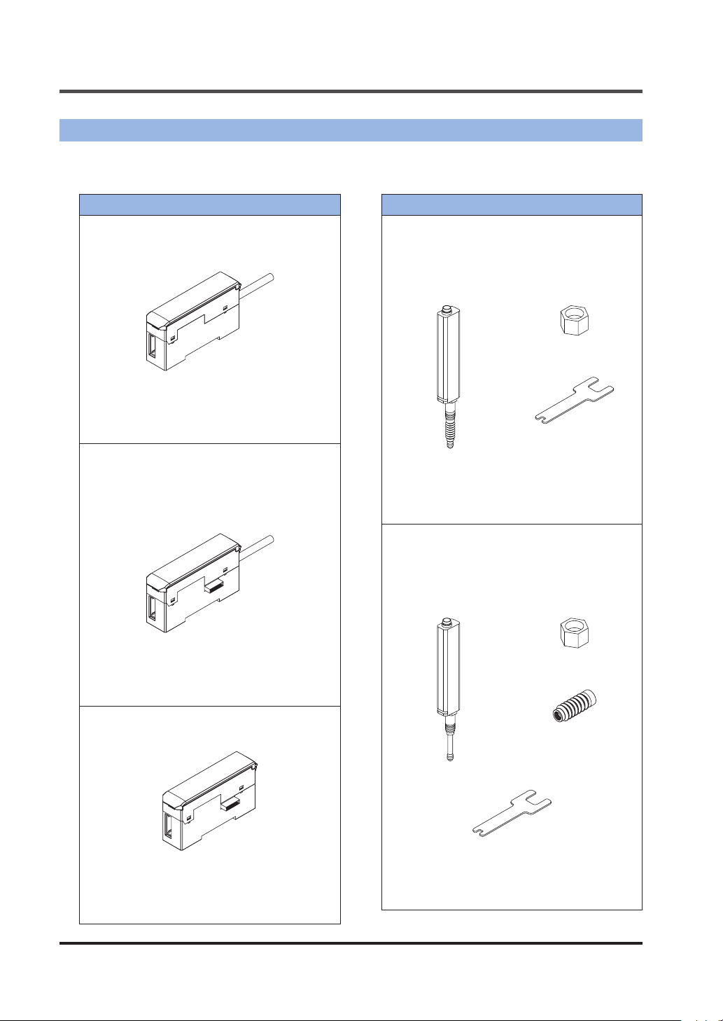
Sensor head (Regular type)
HG-S1032 / General purpose, standard,
32mm type
Sensor head: 1 pc. ●Nut: 1 pc.
●
Sensor head fasten-
●
ing wrench: 1 pc.
Instruction Manual (English / Japa-
●
nese, Chinese / Korean): 2 pcs.
General Information for Safety, Compliance,
●
and Instructions (23 languages): 1 pc.
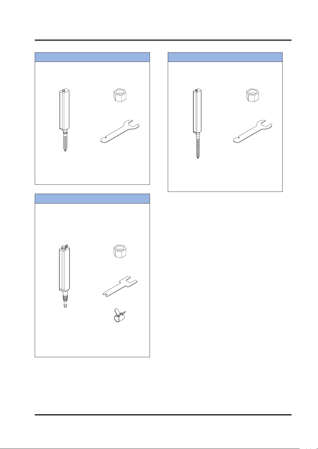
Sensor head (Air-driven type)
HG-S1010-AC / General purpose, airdriven type
HG-S1110-AC / High accuracy, air-driven
type
Sensor head: 1 pc. ●Nut: 1 pc.
●
Sensor head (Regular type)
HG-S1050 / General purpose, standard,
50mm type
Sensor head: 1 pc.
●
Instruction Manual (English / Japa-
●
nese, Chinese / Korean): 2 pcs.
General Information for Safety, Compliance,
●
and Instructions (23 languages): 1 pc.
Nut: 1 pc.
●
Sensor head fasten-
●
ing wrench: 1 pc.
Sensor head fasten-
●
ing wrench: 1 pc.
Air tube clamp: 1 pc.
●
Instruction Manual (English / Japa-
●
nese, Chinese / Korean): 2 pcs.
General Information for Safety, Compliance,
●
and Instructions (23 languages): 1 pc.
WUME-HGS-7 2-3
BEFORE USING THIS PRODUCT
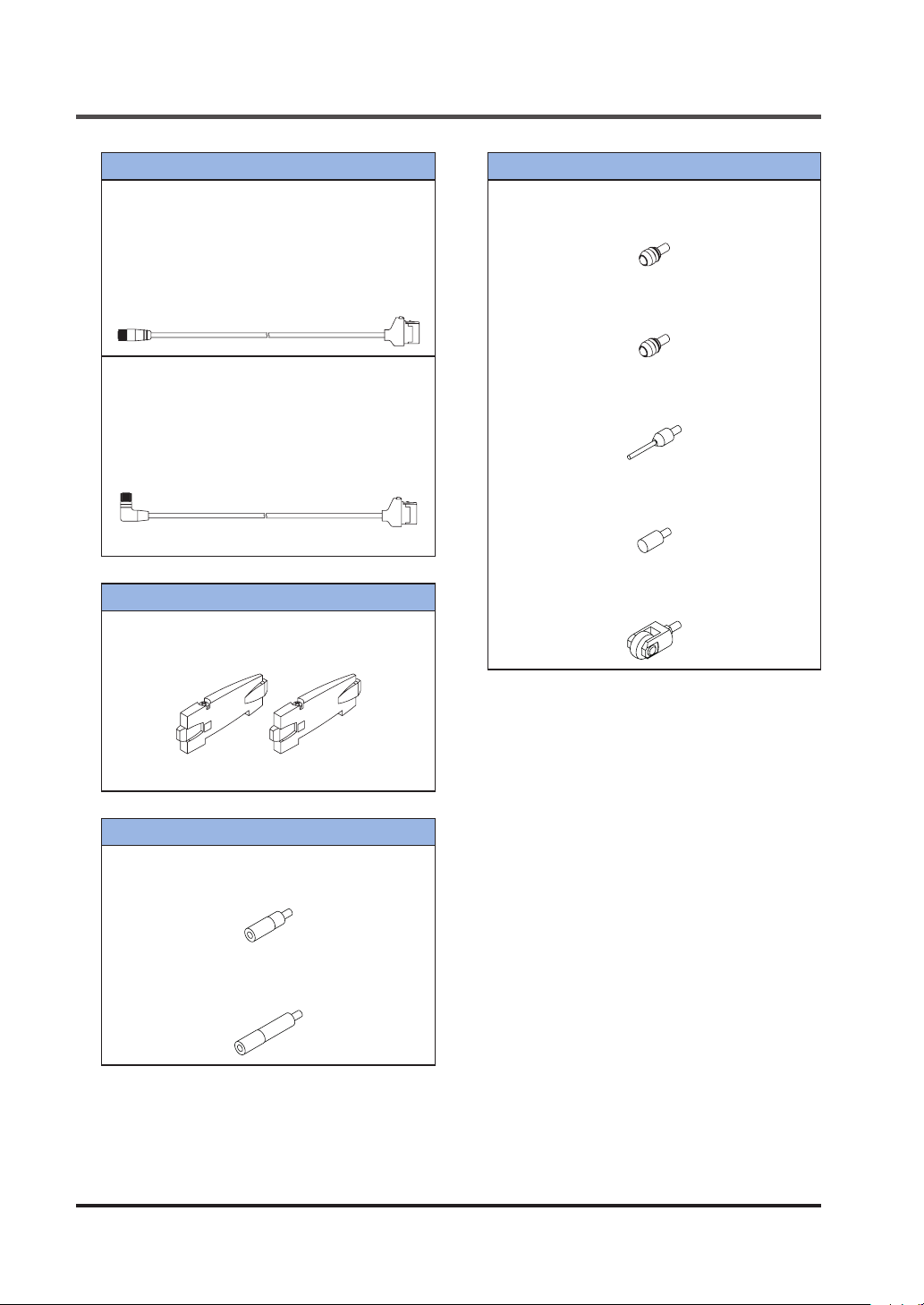
Sensor head connection cable
Straight connector
CN-HS-C3 / Cable length 3m
CN-HS-C7 / Cable length 7m
CN-HS-C10 / Cable length 10m
CN-HS-C20 / Cable length 20m
Connection cable: 1 pc.
●
L-shaped connector
CN-HS-C3L / Cable length 3m
CN-HS-C7L / Cable length 7m
CN-HS-C10L / Cable length 10m
CN-HS-C20L / Cable length 20m
Connection cable: 1 pc.
●
Note: Cannot be connected to an air-driven type.
End plate (Option)
MS-DIN-E / End plate
Plate: Set of 2 pcs.
●
Probe (Option)
HG-SS10Cx5 / Standard type
Probe: Set of 5 pcs.
●
HG-SS10H / Super-hard type
Probe: 1 pc.
●
HG-SS20H / Super-hard needle type
Probe: 1 pc.
●
HG-SS30S / Flat-seated type
Probe: 1 pc.
●
HG-SS40U / Roller type
Probe: 1 pc.
●
Instruction manual
●
Joint (Option)
HG-SJ15 / Length 15mm type
Joint: 1 pc.
●
HG-SJ25 / Length 25mm type
Joint: 1 pc.
●
WUME-HGS-72-4
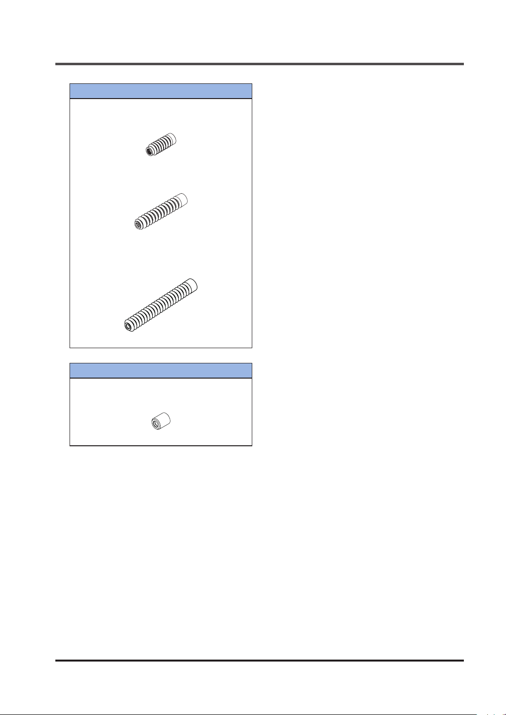
Rubber bellows (Option)
HG-SGN10x5 / 10mm type
Bellows: Set of 5 pcs.
●
HG-SGN32x5 / 32mm type
Bellows: Set of 5 pcs.
●
Note: Cannot be connected to an air-driven type.
BEFORE USING THIS PRODUCT
HG-SGN50x5
Bellows: Set of 5 pcs.
●
Note: Cannot be connected to an air-driven type.
50mm type
/
Seal cap (Option) (Note)
HG-SASCx5 / Air-driven type
Probe: Set of 5 pcs.
●
Note: Cannot be connected to a regular type.
WUME-HGS-7 2-5
BEFORE USING THIS PRODUCT
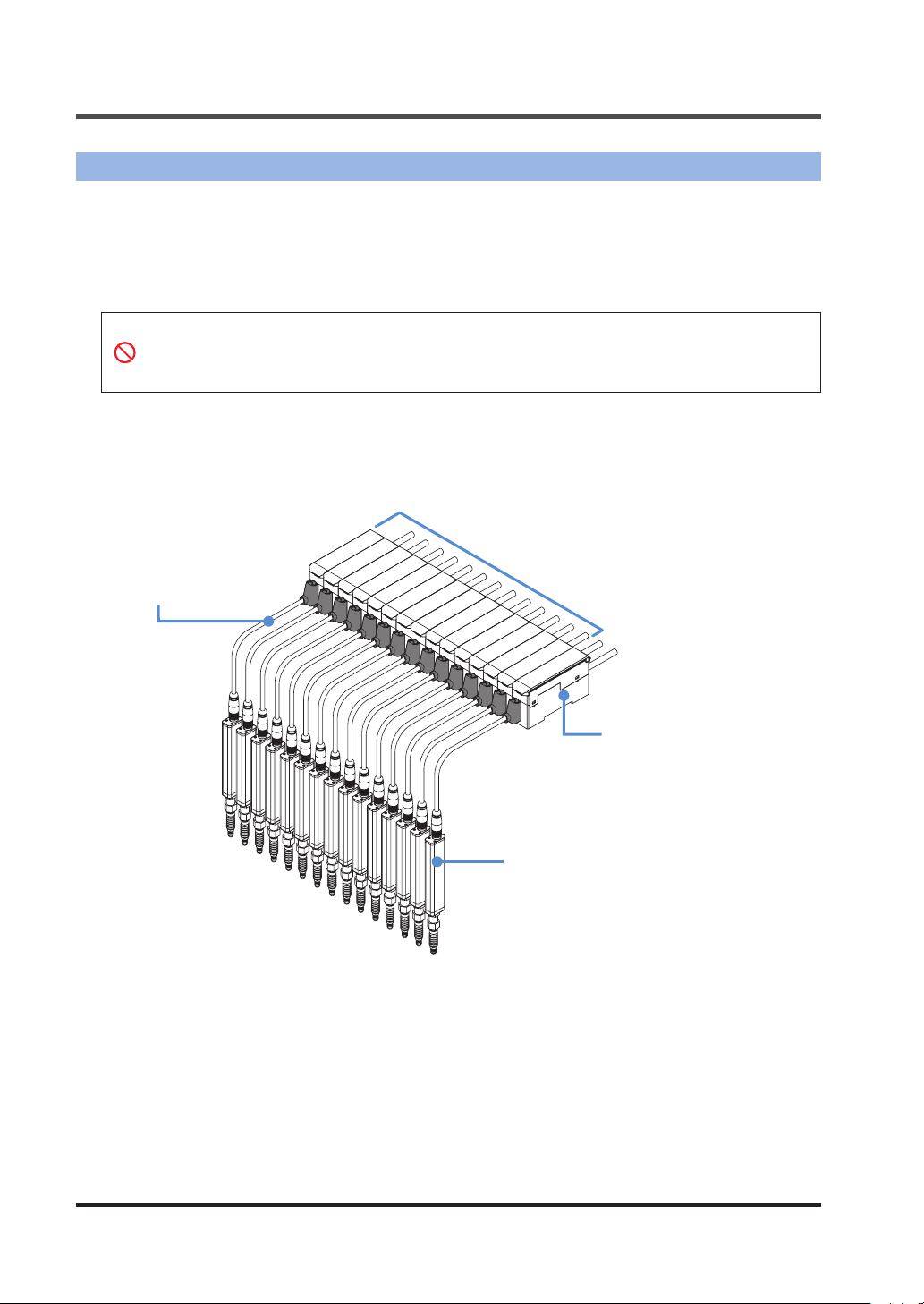
2-2 System Conguration
HG-S
The
For the controllers, master units (2 types) and slave units (5 types) are available. Up to 15 slave
units can be connected per master unit. (When communication unit consolidated: up to 14 slave
units)
For the sensor heads, 8 types are available.
Sensor head connection cable
Straight connector
CN-HS-C3
CN-HS-C7
CN-HS-C10
CN-HS-C20
L-shaped connector
CN-HS-C3L
CN-HS-C7L
CN-HS-C10L
CN-HS-C20L
series consists of controllers, sensor head connection cables, and sensor heads.
● When connecting slave units to a master unit, connect only NPN output types, or only
PNP output types. Dissimilar output types cannot be connected together.
● To use an air-driven type and 50mm type sensor head, connect to an
HG-SC
series con-
troller manufactured in February 2019 or later.
/ Cable length 3m
/ Cable length 7m
/ Cable length 10m
/ Cable length 20m
/ Cable length 3m
/ Cable length 7m
/ Cable length 10m
/ Cable length 20m
Controller - Slave unit
HG-SC111
HG-SC111-P
HG-SC112
HG-SC112-P
HG-SC113
/ High-performance, NPN output type
/ High-performance, PNP output type
/ Standard, NPN output type
/ Standard, PNP output type
/ Wire-saving
Controller - Master unit
HG-SC101
HG-SC101-P
Sensor head
HG-S1010
General purpose, standard, 10mm type
HG-S1010R
General purpose, low measuring force, 10mm type
HG-S1110
High-performance, standard, 10mm type
HG-S1110R
High-performance, low measuring force, 10mm type
HG-S1032
General purpose, standard, 32mm type
HG-S1050
General purpose, standard, 50mm type
HG-S1010-AC
General purpose, air-driven type
HG-S1110-AC
High accuracy, air-driven type
/
/
/
/
/
/
/
/
/ NPN output type
/ PNP output type
WUME-HGS-72-6
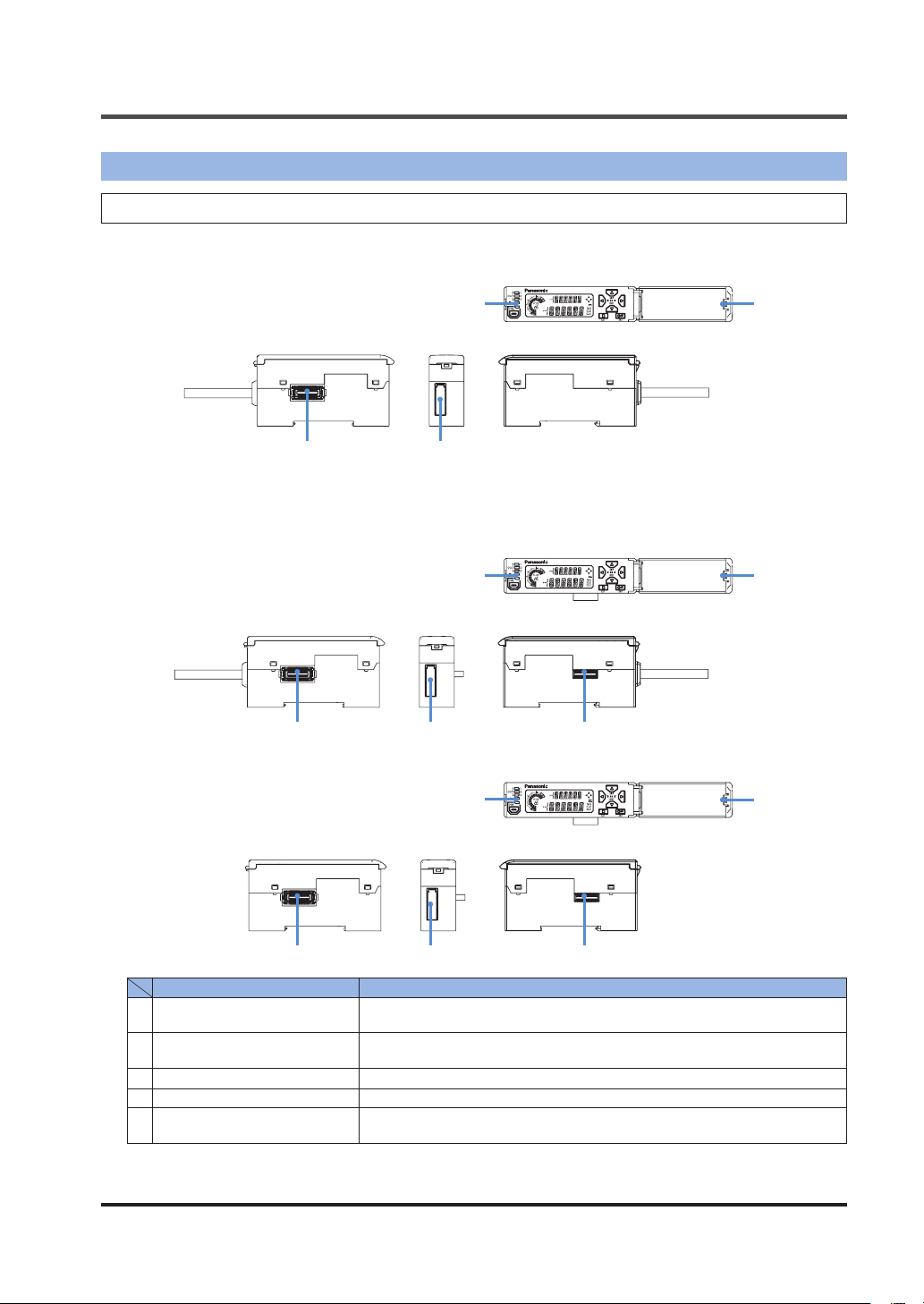
2-3 Description of Parts
2-3-1 Controller
HG-SC101 / Master unit, high-performance type
HG-SC101-P / Master unit, high-performance type
1 2
HG-SC111 / Slave unit, high-performance type
HG-SC111-P / Slave unit, high-performance type
HG-SC112 / Slave unit, standard type
HG-SC112-P / Slave unit, standard type
BEFORE USING THIS PRODUCT
53
1 2
HG-SC113 / Slave unit, wire-saving type
1 2
Name Function
1
Female connector
Sensor head connection cable
2
connector
3
Digital display / operation unit For details, refer to the following page.
4
Male connector For connection to a master unit or slave unit.
Digital display / operation
5
cover
For connection to a slave unit. Remove the connector cover before connecting to a slave unit.
Connects a sensor head connection cable (option).
Keep closed when not using.
3
4
3
4
5
5
WUME-HGS-7 2-7
BEFORE USING THIS PRODUCT
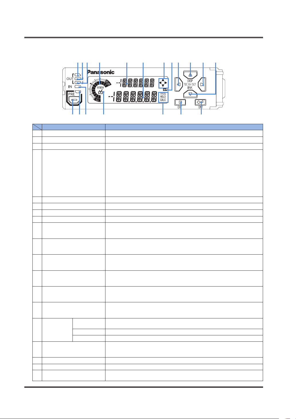
Digital display / operation unit
●
1 42 3 5 6 7 8
Name Function
1
Output 1 indicator (Orange) Lights up when output 1 is ON.
2
Output 2 indicator (Orange) Lights up when output 2 is ON.
3
Output 3 indicator (Orange) Lights up when output 3 is ON.
• Shows increases / decreases of the judgment value by meter display.
• The lowest two gradations show the LOW judgment, and the highest two
gradations show the HIGH judgment.
•
4
Circle meter (Orange, Green)
5
Digital display / SUB (Green) Shows the setting item. The item set using display switching mode appears.
6
Digital display / MAIN (White) Shows the judgment value and setting data.
7
Guide mark / arrow key (White)
8
Guide mark / ENT (White) Lights up when the ENTER key is enabled while conguring settings.
9
LEFT key
10
UP key
11
RIGHT key
12
DOWN key
13
ENTER key
14
EXIT key
TRIG (White)
15
Status mark
16
Copy checkmark (Orange)
17
Input indicator (White) Lights up when external input 1, 2, or 3 is ON.
18
Preset indicator (Green) Lights up when the preset function is used.
19
Preset key
HOLD (White) Lights up while the judgment value is held.
CALC (White) Lights up when set to calculation mode with a slave unit connected.
Green lights up when the judgment is GO. Orange lights up when the judgment is LOW / HIGH.
•
When the HIGH setting is set to a lower value than the LOW setting, all indicators turn OFF.
• To show the count, long-press the LEFT / RIGHT / UP / DOWN key for 2
seconds in the base screen.
• The number of setting items in the level lights up, and the order of the setting times is shown by blinking.
Lights up when the LEFT / RIGHT / UP / DOWN key is enabled while conguring settings.
• Use to change setting items and settings when conguring settings, and to
move through set value digits.
• Long-press for 2 seconds in the base screen to enter teaching mode.
•
Use to change setting items when conguring settings, and to change numeric set values.
•
Long-press for 2 seconds in the base screen to enter display switching mode.
• Short-press in the base screen to nely adjust the HIGH set value.
• Use to change setting items and settings when conguring settings, and to
move through set value digits.
• Long-press for 2 seconds in the base screen to enter setting mode.
•
Use to change setting items when selecting settings, and to change numeric set values.
• Long-press for 2 seconds in the base screen to enter bank mode.
• Short-press in the base screen to nely adjust the LOW set value.
• Use to select setting items and nalize settings when conguring settings.
• Long-press for 3 seconds together with the EXIT key in the base screen to
activate or cancel key lock.
• Use to exit a setting item or cancel a setting when conguring settings.
• Long-press for 3 seconds together with the ENTER key in the base screen
to activate or cancel key lock.
Lights up while the trigger input (external input) is ON.
Lights up during sampling when self-hold is set.
When conguring master unit settings, “COPY” lights up for setting items
that can be copied to slave units. A checkmark lights up for items selected
for copying, and the settings are copied when copying is executed.
When short-pressed in the base screen, the preset function turns ON.
When long-pressed for 2 seconds in the base screen, the preset function turns OFF.
9 10 11
14 1319 1718 1516
12
WUME-HGS-72-8
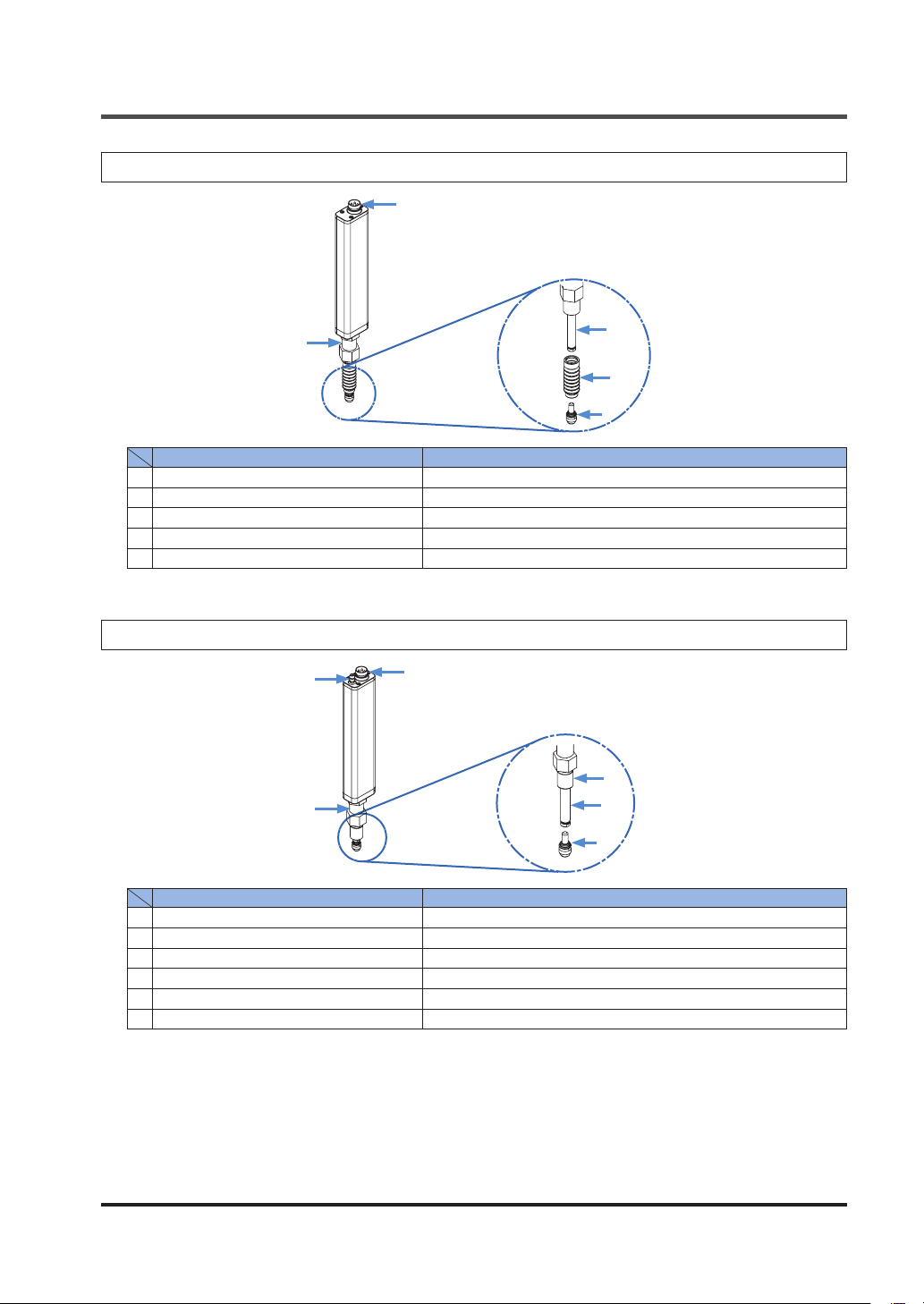
2-3-2 Sensor Head (Regular Type)
1
BEFORE USING THIS PRODUCT
2
Name Function
1
Sensor head connection cable connector Connects the sensor head connection cable.
2
Fastener Fastens the sensor head using the provided nut.
3
Spindle Detects the amount of movement.
4
Rubber bellows Protects the spindle.
5
Probe Ceramic measurement probe.
3
4
5
2-3-3 Sensor Head (Air-Driven Type)
2
3
1
<When air is supplied>
4
5
6
Name Function
1
Sensor head connection cable connector Connects the sensor head connection cable.
2
Air tube joint Connects the air tube.
3
Fastener Fastens the sensor head using the provided nut.
4
Seal cap Protects the spindle.
5
Spindle Detects the amount of movement.
6
Probe Ceramic measurement probe.
WUME-HGS-7 2-9
BEFORE USING THIS PRODUCT
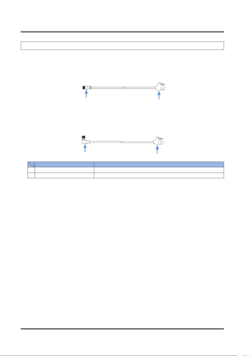
2-3-4 Sensor Head Connection Cable
Straight connector
CN-HS-C3
CN-HS-C7
CN-HS-C10
CN-HS-C20
/ Cable length 3m
/ Cable length 7m
/ Cable length 10m
/ Cable length 20m
1
2
L-shaped connector (Note)
CN-HS-C3L
CN-HS-C7L
CN-HS-C10L
CN-HS-C20L
1
Sensor head connector Connects to the sensor head cable connector on the sensor head.
2
Controller connector Connects to the sensor head cable connector on the controller.
Note: Cannot be connected to an air-driven type.
/ Cable length 3m
/ Cable length 7m
/ Cable length 10m
/ Cable length 20m
1
Name Function
2
WUME-HGS-72-10

Chapter 3 INSTALLATION AND
CONNECTIONS
3-1 Mounting the Controller ······························································ 3-2
3-1-1 Mounting on a DIN Rail ·························································· 3-2
3-1-2 Removing from a DIN Rail ······················································· 3-2
3-2 Attaching the Sensor Head ························································· 3-3
3-3 Wiring the Controller Connector on the Sensor Head Connection Cable 3-5
3-3-1 Disassembly Procedure ·························································· 3-5
3-3-2 Wiring Procedure ·································································· 3-5
3-4 Connecting the Controller and Sensor Head ··································· 3-7
3-4-1 Attaching the Sensor Head and Sensor Head Connection Cable ····· 3-7
3-4-2 Removing the Sensor Head and Sensor Head Connection Cable ···· 3-8
3-4-3 Connecting the Air Tube (Air-Driven Type Only) ··························· 3-9
3-4-4 Disconnecting the Air Tube (Air-Driven Type Only) ·······················3-9
3-4-5 Air Circuit (Recommended) (Air-Driven Type Only) ······················· 3-10
3-4-6 Attaching the Controller and Sensor Head Connection Cable ·········3-11
3-4-7 Removing the Controller and Sensor Head Connection Cable ········ 3-11
3-5 Connecting Controllers ······························································· 3-12
3-5-1 Connection Method ······························································· 3-13
3-5-2 Removal Method ··································································· 3-15
3-6 Connection Diagrams and I/O Circuit Diagrams ······························· 3-16
3-6-1 Connection Diagrams ····························································· 3-16
3-6-2 I/O Circuit Diagrams······························································· 3-18
3-1
INSTALLATION AND CONNECTIONS
3-1 Mounting the Controller
3-1-1 Mounting on a DIN Rail
Insert the rear of the mounting part into the DIN rail.
1.
While pressing down on the rear of the mounting part, insert the front of the mounting part
2.
into the DIN rail.
2
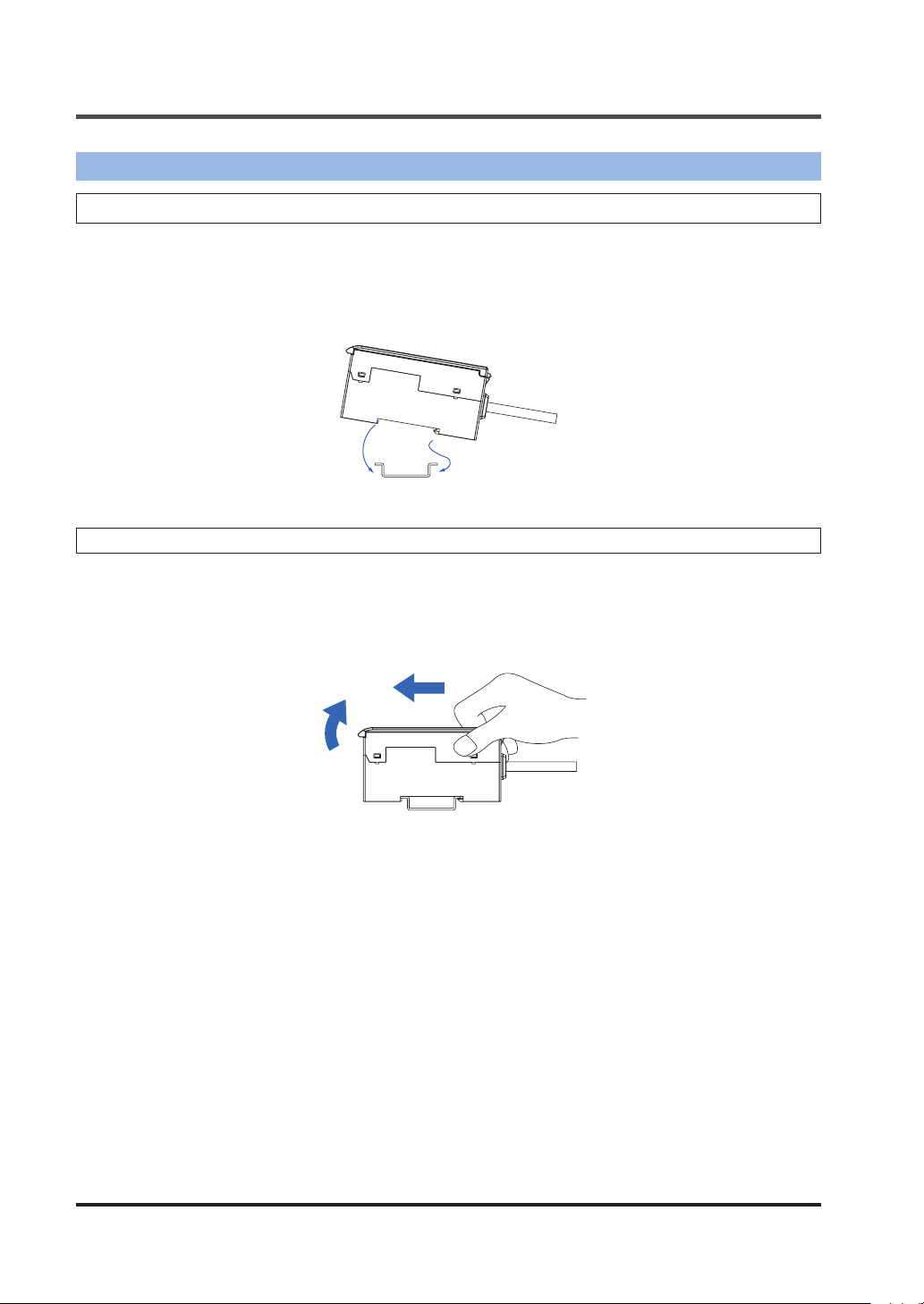
3-1-2 Removing from a DIN Rail
Grasp the product and push forward.
1.
Lift the front to remove.
2.
2
1
1
WUME-HGS-73-2
INSTALLATION AND CONNECTIONS
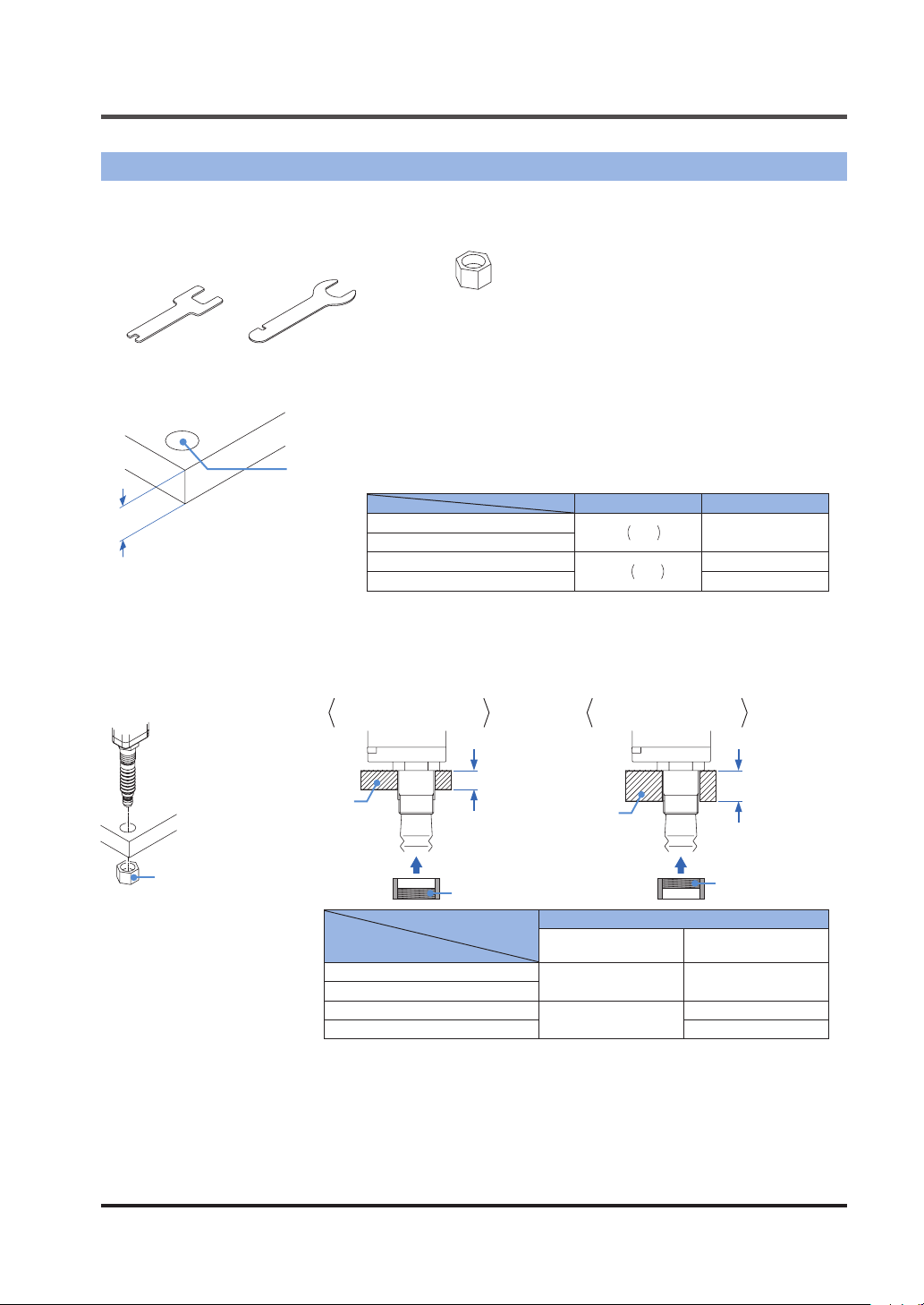
3-2 Attaching the Sensor Head
Sensor head accessories
●
Sensor head fastening wrench
10mm type
Air-driven type
Open a hole in the housing in which the sensor head will be mounted.
1.
Housing thickness
32mm/50mm type
Mounting hole
HG-S1010(R
HG-S1010-AC, HG-S1110-AC
HG-S1032
HG-S1050
Mounting nut
HG-S1110(R
),
Housing thickness Mounting hole
)
ø8H7
ø12H7
+0.015
mm 6.5 to 12.5mm
0
+0.018
0
mm
6.5 to 10.5mm
6.5 to 12.5mm
nsert the sensor head into the hole you opened in the housing, and fasten provisionally
2.
with the provided mounting nut. The mounting direction of the mounting nut diers according to the thickness of the housing. For the mounting direction, see the table below.
Mounting nut (accessory)
Mounting bolt / threaded
part facing down
Housing
HG-S1010(R
HG-S1010-AC, HG-S1110-AC
HG-S1032
HG-S1050
HG-S1110(R
),
Housing thickness
Thread
)
Mounting bolt / threaded
part facing up
Housing thickness
Housing
Thread
Housing thickness
threaded part facing
down
6.5 to 10mm 10 to 12.5mm
6.5 to 8.5mm
threaded part facing
8.5 to 10.5mm
8.5 to 12.5mm
up
WUME-HGS-7 3-3
INSTALLATION AND CONNECTIONS
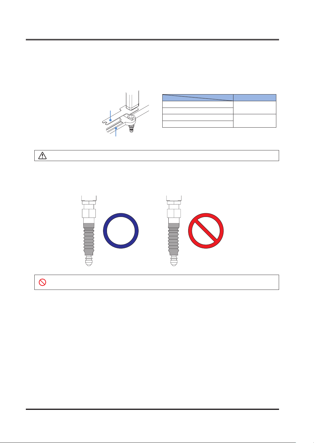
Fasten the sensor head.
3.
When fastening the sensor head, tighten the mounting nut with a wrench while holding the
sensor head in place with the provided sensor head fastening wrench as shown below.
When mounting the sensor head, note that the tightening torque must not exceed the value
shown in the table below.
Tightening torque
Sensor head fastening wrench (accessory)
Wrench
When tightening the mounting nut on the regular type, take care not to damage the rubber bellows.
On the regular type, make sure that the rubber bellows have not become deformed as
4.
shown below.
If the rubber bellows is deformed, rotate the bellows to restore to the normal shape.
HG-S1010(R)、HG-S1110(R
HG-S1010-AC、HG-S1110-AC
HG-S1032
HG-S1050
)
12.5N・m
15N・m
If the rubber bellows is deformed, a load will occur when the spindle operates and damage
may result.
WUME-HGS-73-4
INSTALLATION AND CONNECTIONS
3-3 Wiring the Controller Connector on the Sensor Head Connection
Cable
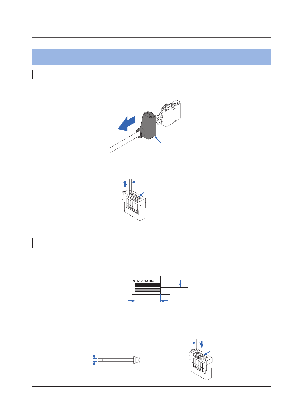
3-3-1 Disassembly Procedure
Slide the protective cover in the direction of the arrow.
1.
Protective cover
Press down on the wire insertion hole lever (white) with a at-head screwdriver (tip width
2.
2mm or less), and remove the wire.
Flat-head screwdriver
Lever (white)
3-3-2 Wiring Procedure
Using the "STRIP GAUGE" on the side of the unit, strip the wire so that the core wire length
1.
is 7 to 8mm, and twist the core wires several times.
Wire
Core wire
length
7 to 8mm
Using a at-head screwdriver with a tip width of 2mm or less, press down until the lever
2.
(white) on the operation unit until the lever locks.
Flat-head screwdriver
Tip width
2mm or less
WUME-HGS-7 3-5
Lever (white)
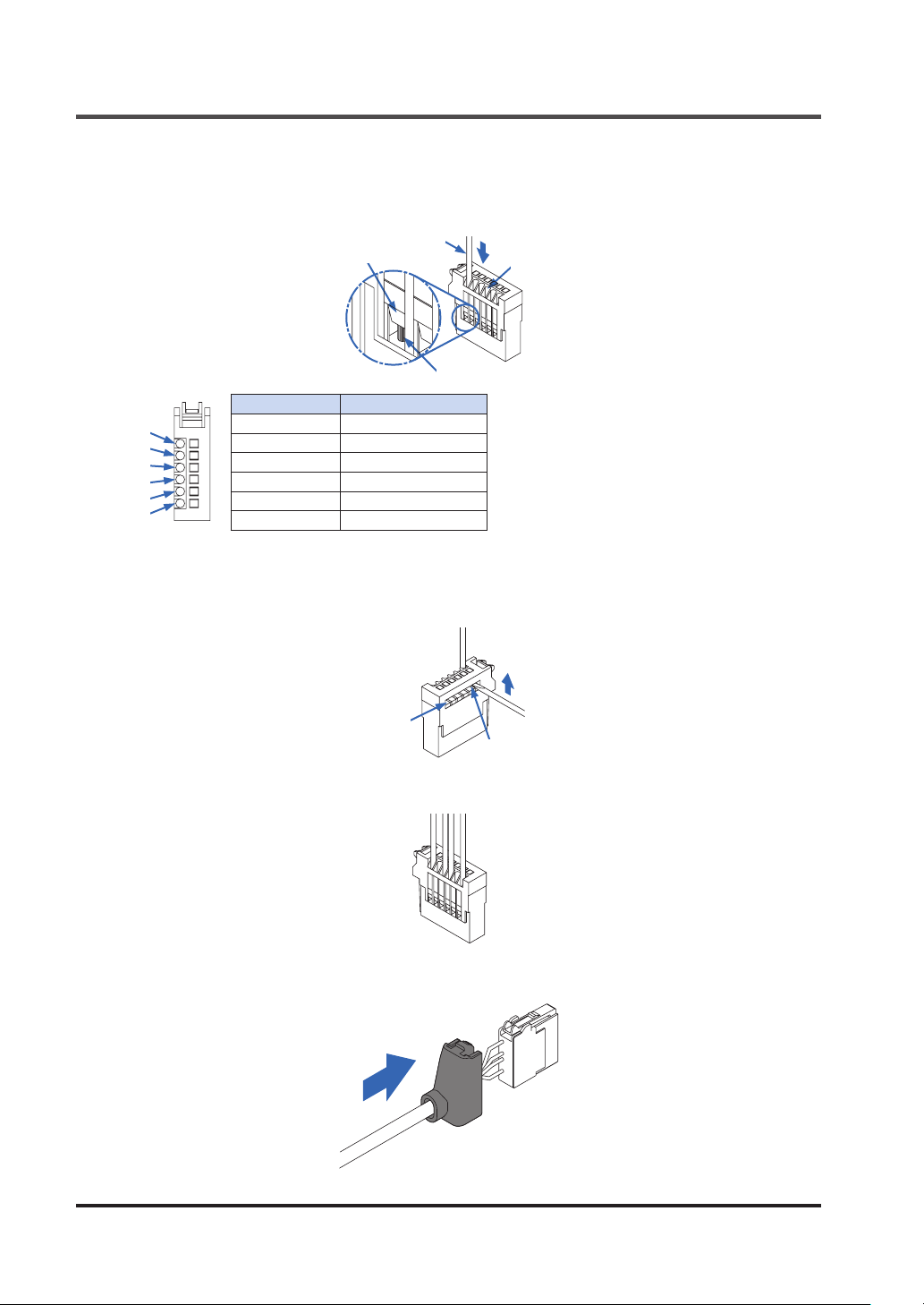
INSTALLATION AND CONNECTIONS
Insert the wire rmly into the wire insertion hole. Make sure that the jacketed part of the
3.
wire has entered the wire insertion hole and the tips of the core wires have passed through
the connection part as shown below.
Jacketed part of wire
Connection part
Core wire tip
Terminal No. Connection cable
1
2
3
4
5
6
Insert the tip of the at-head screwdriver into the release hole so that it contacts the bottom
4.
of the lever (white), and move the tip of the at-head screwdriver up. The lever (white) will
make a "click" sound when it returns to its original position, and the wire will be locked.
1 Red
2 ―
3 White
4 Green
5 ―
6 Black
Wire insertion hole
Release hole
Lever (white)
Pull on the wire gently to ensure that it does not come out.
5.
Slide the protective cover in the direction of the arrow to return the cover to its original position.
6.
WUME-HGS-73-6
INSTALLATION AND CONNECTIONS
3-4 Connecting the Controller and Sensor Head
Connect the controller and the sensor head using the sensor head connection cable
/ CN-HS-C□L
.
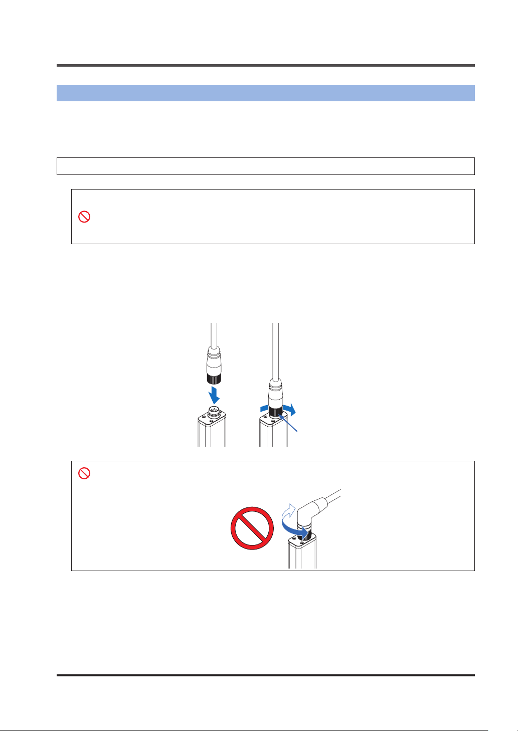
3-4-1 Attaching the Sensor Head and Sensor Head Connection Cable
● After attaching the connector, verify that the connector is rmly tightened.
If loose, the connector may come o and an error will result.
● When attaching the sensor head connection cable to this product, take care not to apply
force to the product.
● The L-shaped
Insert the sensor head connection cable into the connector for the sensor head connection
1.
cable on the sensor head.
Turn the fastening ring on the sensor head connector in the direction shown and tighten
2.
rmly.
CN-HS-C□L
1
connector cannot be connected to an air-driven type.
2
CN-HS-C□
Fixing ring
Do not turn the connector on the L-shaped connector
Risk of damage.
WUME-HGS-7 3-7
CN-HS-C□L
.
INSTALLATION AND CONNECTIONS
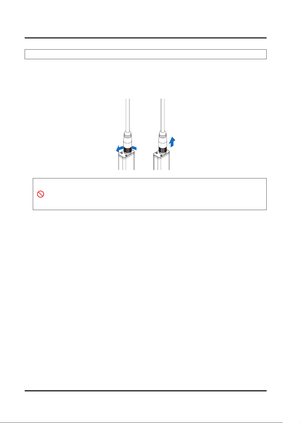
3-4-2 Removing the Sensor Head and Sensor Head Connection Cable
Turn the fastening ring on the sensor head connector in the direction of the arrow to loosen
1.
the ring.
Grasp the sensor head connector and pull up to remove.
2.
2
1
● When disconnecting, always make sure that the fastening ring has been completely loos-
ened before pulling out the cable. Risk of damage if you pull the cable with excessive
force (15N or more) with the fastening ring tightened.
● If changing the type of sensor head to be connected, always switch the power OFF then
ON.
WUME-HGS-73-8
INSTALLATION AND CONNECTIONS
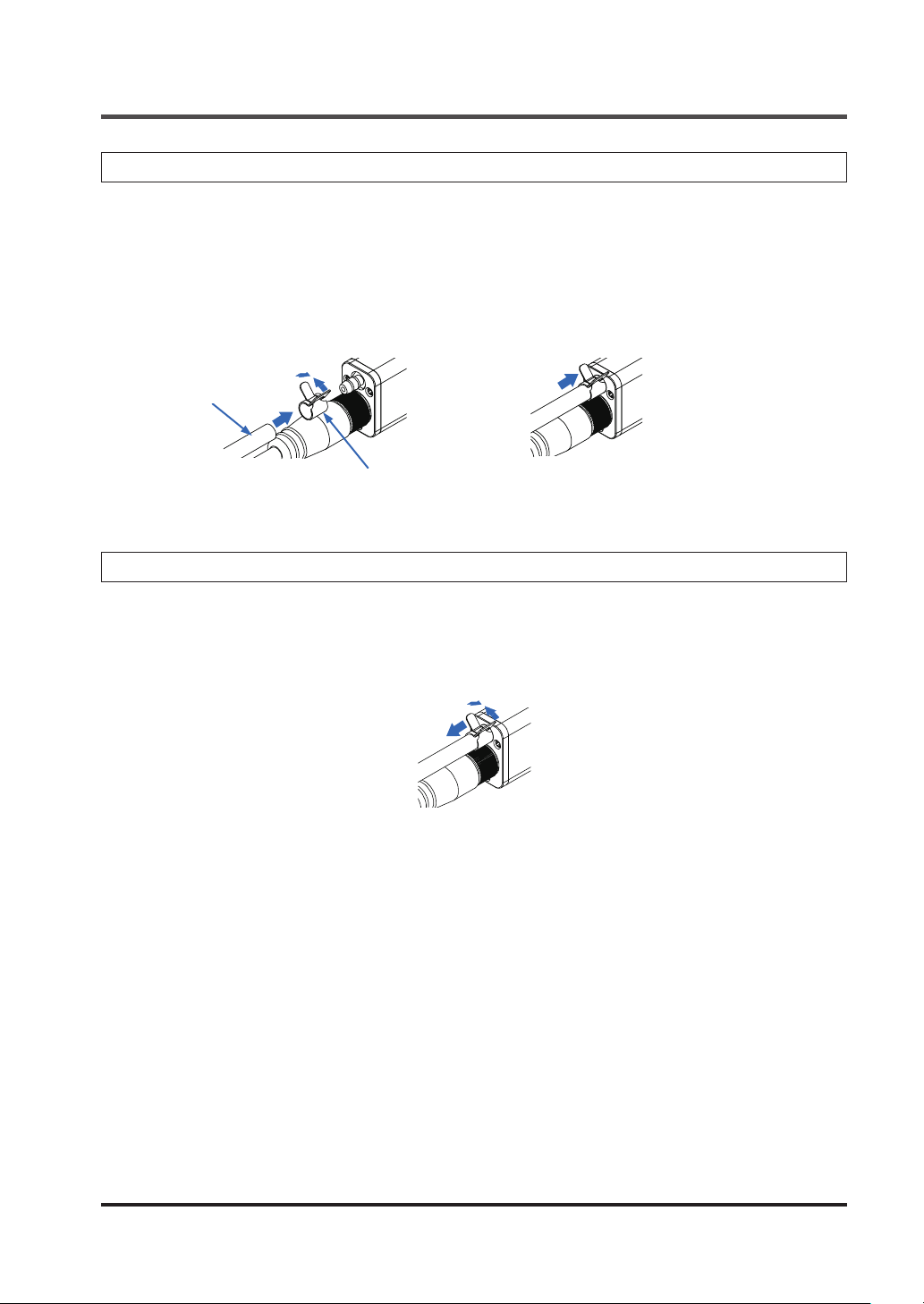
3-4-3 Connecting the Air Tube (Air-Driven Type Only)
While loosening the air tube clamp, slide it from the tip of the air tube and then release it
1.
when it reaches halfway through the tube.
Insert the tip of the air tube until it reaches the root of the joint on the sensor head.
2.
Move the air tube clamp and secure the tip of the air tube.
3.
ø4mm air tube
Air tube clamp
(Accessory)
3-4-4 Disconnecting the Air Tube (Air-Driven Type Only)
While loosening the air tube clamp, move it halfway through the air tube.
1.
Grasp the sensor head and pull out the air tube.
2.
Note: Take care not to lose the air tube clamp.
WUME-HGS-7 3-9
INSTALLATION AND CONNECTIONS
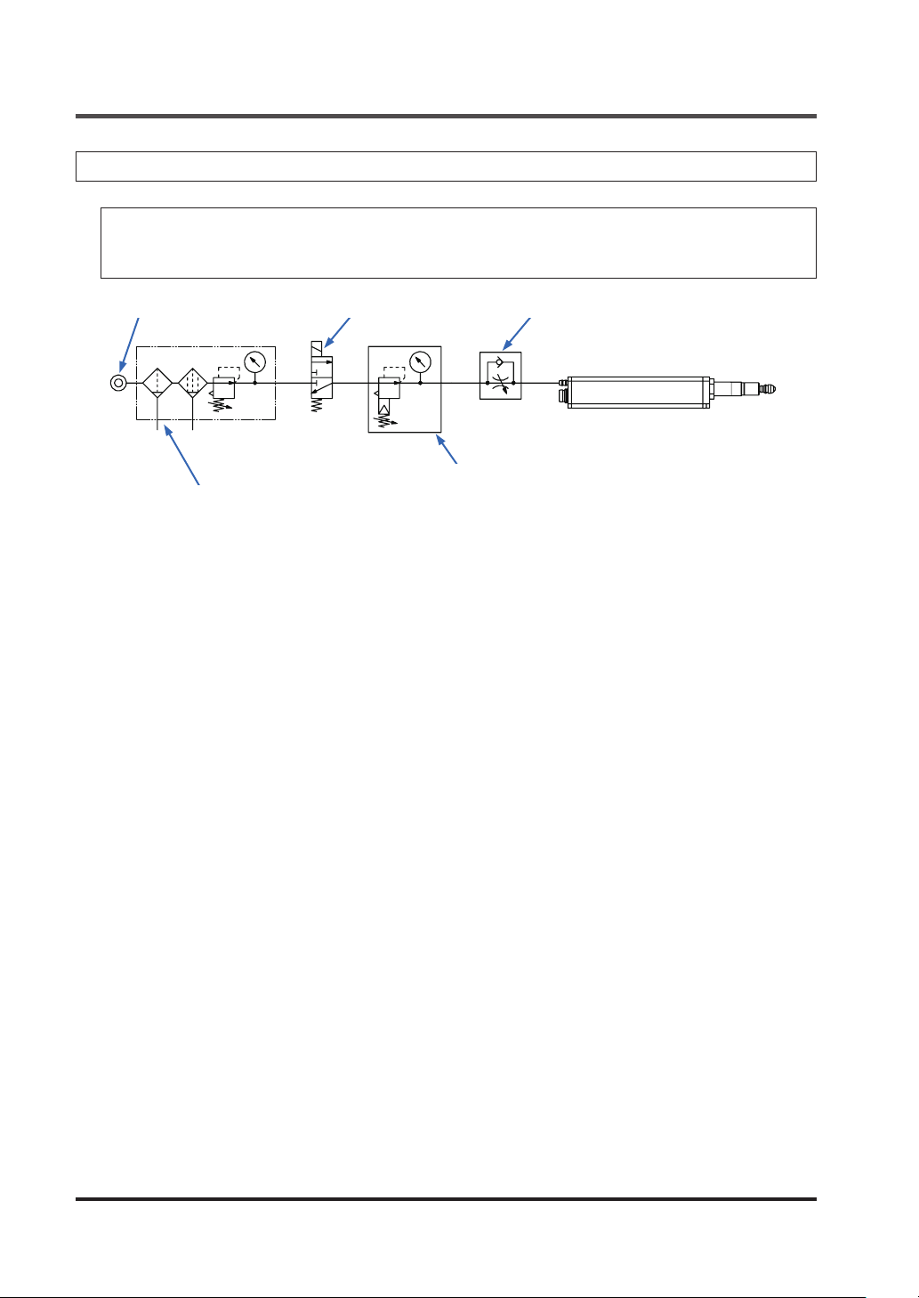
3-4-5 Air Circuit (Recommended) (Air-Driven Type Only)
<Reference>
Create an air circuit like the one (recommended) shown in the gure below and, if necessary,
adjust the speed of the spindle with the speed control valve.
Air pressure source 3-port solenoid valve
Precision regulator
Filter + Mist separator + Regulator
Notes: 1)
2) Air pressure may decrease, depending on the length of the air pipe from the air supply source or any
3) The 3-port solenoid valve and speed control valve have their respective mounting directions. Mount
4) A lter with a rated ltration of 5μm or less and a mist separator with a rated ltration of 0.3μm or less
Supply clean air (free from moisture, oil, dust, or other foreign matter) to this product.
pneumatic components (such as needle valves, speed controllers, or mini-lters) that are added. Take
care to ensure that air pressure supply to the product is sucient. Select pneumatic components suit-
able for the supplied air pressure.
each valve in their correct direction by referring to the above diagram.
are recommended.
Speed control valve
WUME-HGS-73-10
 Loading...