How it Works
Log In / Sign Up
Buy Points
How it Works
FAQ
Contact Us
Questions and Suggestions
Users
Panasonic
Loading...
H
HDC27F
hdcdt750
HDCHS700 - HDD SD CAMCORDER
HDCHS80EP
HDCHS900P/PC
HDCSDT750 - HD 3D CAMCORDER
HDCSDX1
9
HDCSDX1 - HD SD CAMCORDER
HDCSX1 - HD VIDEO CAMERA
HDCTM00P/PC
HDCTM15K
HDCTM300 - HD SD CAMCORDER
HDCTM40K
2
HDCTM60K
HDCTM900P/PC
HDC-TMT750
2
HDC-TMT750GC
HDC-TMT750GD
HDC-TMT750GK
2
HDC-TMT750GT
HDC-TMX1GK
HDC-Z10000E
2
HDC-Z10000GC
HDC-Z10000GK
2
HDC-Z10000P
2
HDMI SA-XR700
HDTV P7
HDVC
HDVC-MPCS
2
HDX900
Heat
HeavyDuty Plus MC-V5502
HF008
2
HF-5017W-PA
HFQ
HFQ EE26
HFS014042
4
HFS014042E
HFS045200E
HFS100300
7
HFS100300E
HF-S12032
7
HFS12032E
HFS12060E
3
HFS14140E
HFS1442AE
HFS35100
8
HFS45150
8
HFSA100300
8
HG-C
HG-C1030
5
HGC1030L3-P
2
HG-C1030L3-P-J
2
HG-C1030-P
5
HG-C1050
6
HG-C1050L3-P
2
HG-C1050L3-P-J
2
HG-C1050-P
5
HG-C1100
6
HG-C1100L3-P
2
HG-C1100L3-P-J
2
HG-C1100-P
5
HG-C1200
4
HGC1200L3-P
2
HG-C1200L3-P-J
2
HG-C1200-P
3
HG-C1400
4
HG-C1400L3-P
2
HG-C1400L3-P-J
2
HG-C1400-P
3
HG-S
2
HG-S1010
HG-S1010R
HG-S1110
HG-S1110R
HG-SC
HG-T
3
HGT100B - KX - VoIP Phone
HG-T1010
HG-TC
HG-TC101
2
HG-TC101-P
2
HG-TC111
2
HG-TC111-P
2
HG-TC113
2
HH014AE
HH014E
HH020
5
HH020AE
2
HH025E
2
HH025K
hh700
hh900
HH950
2
HHR110AAO
2
HHR120AA
HHR150AA
HHR160A
HHR200A
2
HHR200SCP
Loading...
Loading...
Nothing found
HG-C1030
Easy User Manual
4 pgs
1.8 Mb
0
Instruction Manual
7 pgs
3.56 Mb
0
User guide
13 pgs
10.2 Mb
0
User guide
4 pgs
1.36 Mb
0
User guide [de]
7 pgs
4.67 Mb
0
Table of contents
Loading...
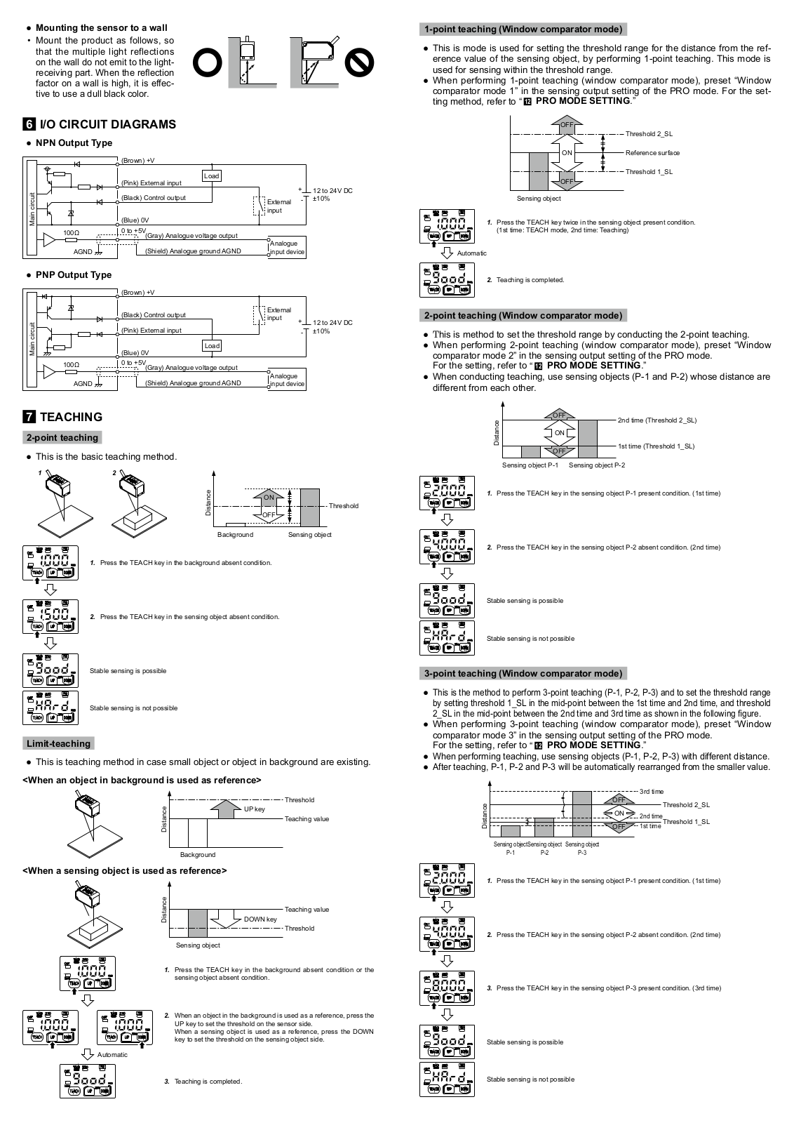
Panasonic HG-C1030, HG-C1050, HG-C1100, HG-C1030-P, HG-C1050-P User guide
...
Panasonic HG-C1030, HG-C1050, HG-C1100, HG-C1030-P, HG-C1050-P, HG-C1100-P User guide
Download
Specifications and Main Features
Frequently Asked Questions
User Manual
Download
Page 1
Page 2
Page 3
Page 4
Loading...
+
hidden pages
Unhide
You need points to download manuals.
1 point = 1 manual.
You can buy points or you can get point for every manual you upload.
Buy points
Upload your manuals