

Page 1
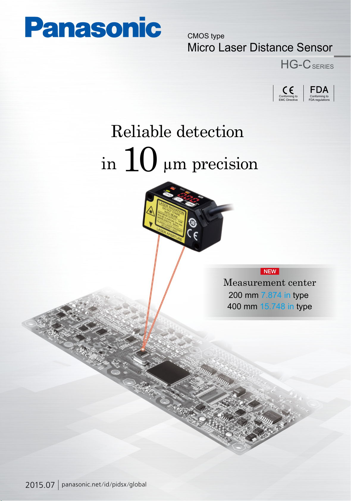
CMOS type
Micro Laser Distance Sensor
Reliable detection
in
10
µm precision
HG-C
Conforming to
EMC Directive
SERIES
Conforming to
FDA regulations
Measurement center
200 mm 7.874 in type
400 mm 15.748 in type
2015.07
panasonic.net/id/pidsx/global
Page 2
MICRO LASER DISTANCE SENSOR
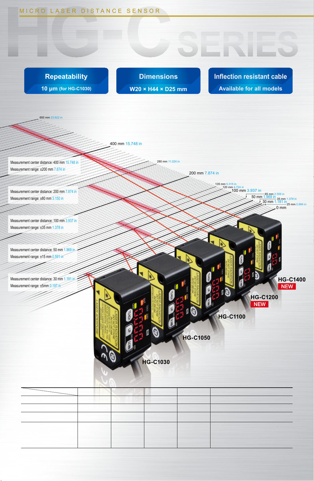
Repeatability
10 μm
600 mm 23.622 in
Measurement center distance: 400 mm 15.748 in
Measurement range: ±200 mm 7.874 in
Measurement center distance: 200 mm 7.874 in
Measurement range: ±80 mm 3.150 in
Measurement center distance: 100 mm 3.937 in
Measurement range: ±35 mm 1.378 in
(for HG-C1030)
W20 × H44 × D25 mm
400 mm 15.748 in
Dimensions
280 mm 11.024 in
Inflection resistant cable
200 mm 7.874 in
Available for all models
135 mm 5.315 in
120 mm 4.724 in
100 mm 3.937 in
65 mm 2.559 in
50 mm 1.969 in
30 mm 1.181 in
35 mm 1.378 in
25 mm 0.984 in
0 mm
Measurement center distance: 50 mm 1.969 in
Measurement range: ±15 mm 0.591 in
Measurement center distance: 30 mm 1.181 in
Measurement range: ±5mm 0.197 in
HG-C110 0
HG-C1050
HG-C1030
Item
Measurement center distance 30 mm 1.181 in 50 mm 1.969 in 100 mm 3.937 in 200 mm 7.874 in 400 mm 15.748 in
Measurement range ±5 mm 0.197 in ±15 mm 0.591 in ±35 mm 1.378 in ±80 mm 3.150 in ±200 mm 7.874 in
Beam diameter
Repeatability
Model No.
HG- C1030 HG-C1050 HG - C110 0 HG- C1200 HG-C1400
Approx.ø50 μm
1.969 mil
10 μm
0.394 mil
Approx.ø70 μm
2.756 mil
30 μm
1.181 mil
Approx.ø120 μm
4.724 mil
70 μm
2.756 mil
Approx.ø300 μm
11.811 mil
200 μm
7.874 mil
Approx.ø500 μm
300 μm 11.811 mil
Measuring distance 200
(
7.874 to 15.748 in
800 μm 31.496 mil
Measuring distance 400
(
15.748 to 23.622 in
HG-C1200
19.685 mil
to
to
400mm
)
600mm
)
HG-C1400
2
Page 3
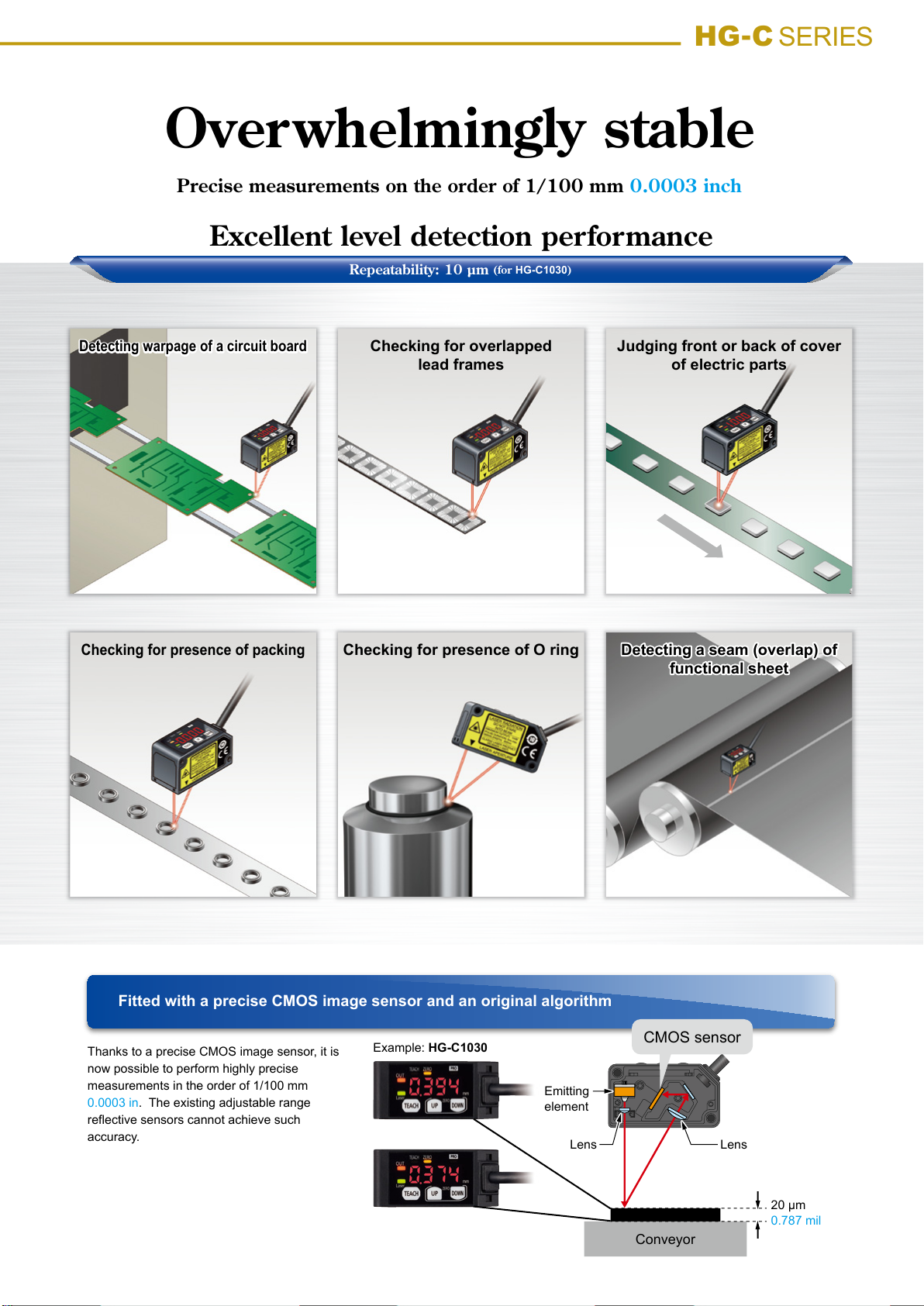
Overwhelmingly stable
Precise measurements on the order of 1/100 mm 0.0003 inch
Fitted with a precise CMOS image sensor and an original algorithm
HG-C
SERIES
Thanks to a precise CMOS image sensor, it is
now possible to perform highly precise
measurements in the order of 1/100 mm
0.0003 in. The existing adjustable range
reflective sensors cannot achieve such
accuracy.
Example: HG-C1030
Conveyor
20 μm
0.787 mil
Excellent level detection performance
Repeatability: 10 μm
(for
HG-C1030
)
Detecting warpage of a circuit board
Checking for overlapped
lead frames
Checking for presence of packing
Checking for presence of O ring
Judging front or back of cover
of electric parts
Detecting a seam (overlap) of
functional sheet
Emitting
element
LensLens
CMOS sensor
3
Page 4
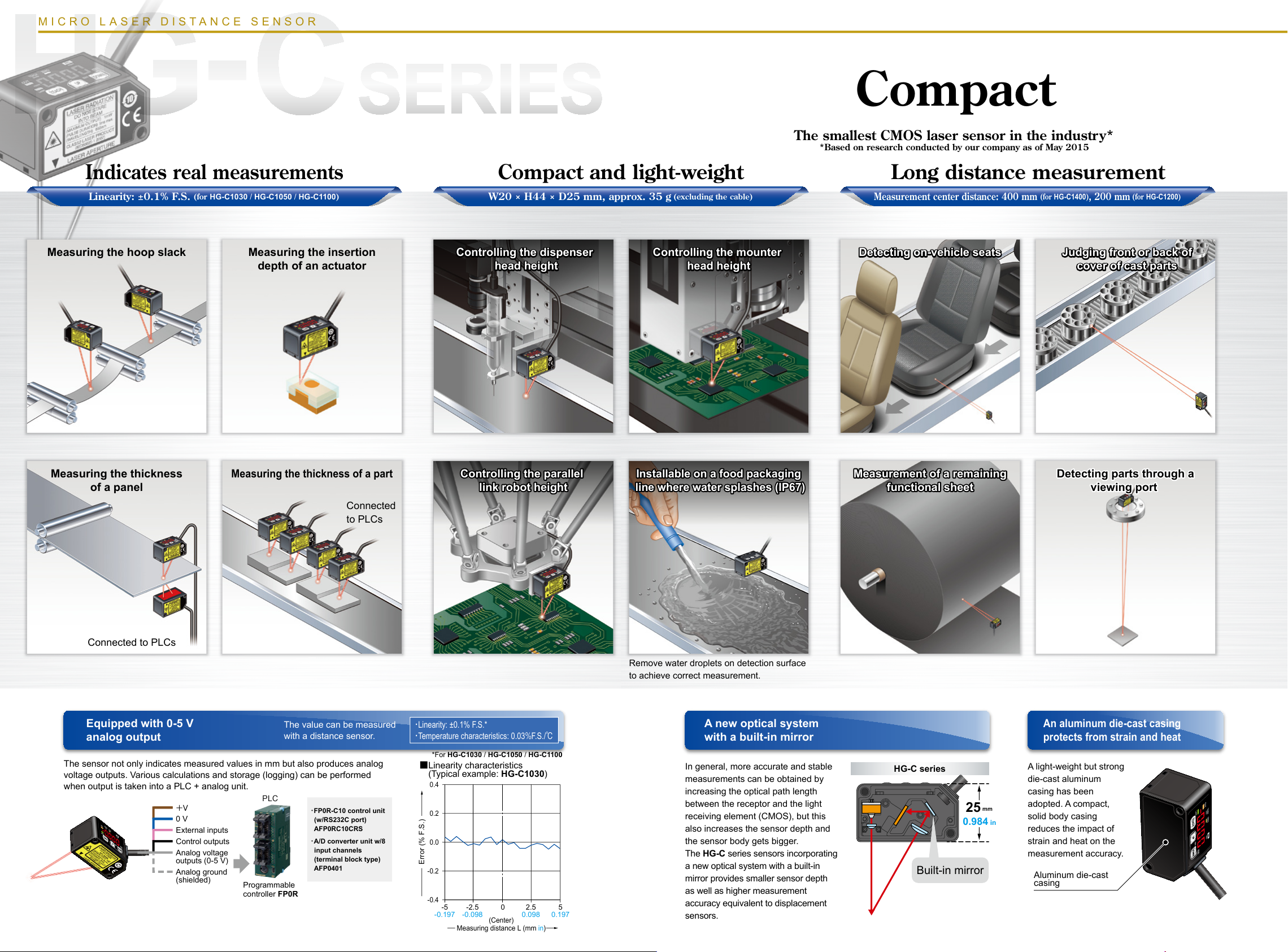
Compact
Compact and light-weight
Equipped with 0-5 V
analog output
An aluminum die-cast casing
protects from strain and heat
A new optical system
with a built-in mirror
MICRO LASER DISTANCE SENSOR
In general, more accurate and stable
measurements can be obtained by
increasing the optical path length
between the receptor and the light
receiving element (CMOS), but this
also increases the sensor depth and
the sensor body gets bigger.
The HG-C series sensors incorporating
a new optical system with a built-in
mirror provides smaller sensor depth
as well as higher measurement
accuracy equivalent to displacement
sensors.
The sensor not only indicates measured values in mm but also produces analog
voltage outputs. Various calculations and storage (logging) can be performed
when output is taken into a PLC + analog unit.
A light-weight but strong
die-cast aluminum
casing has been
adopted. A compact,
solid body casing
reduces the impact of
strain and heat on the
measurement accuracy.
Remove water droplets on detection surface
to achieve correct measurement.
■
Linearity characteristics
(Typical example: HG-C1030)
*For HG-C1030 / HG-C1050 / HG-C1100
PLC
・
FP0R-C10 control unit
(w/RS232C port)
AFP0RC10CRS
・
A/D converter unit w/8
input channels
(terminal block type)
AFP0401
Programmable
controller FP0R
+V
0 V
External inputs
Control outputs
Analog voltage
outputs (0-5 V)
Analog ground
(shielded)
・
Linearity: ±0.1% F.S.*
・
Temperature characteristics: 0.03%F.S./
℃
-0.4
-0.2
0.0
0.2
0.4
-5 -2.5 0 2.5 5
-0.197 -0.098 0.098 0.197
(Center)
Measuring distance L (mm in)
Error (% F.S.)
The value can be measured
with a distance sensor.
Indicates real measurements
The smallest CMOS laser sensor in the industry*
*Based on research conducted by our company as of May 2015
Measurement center distance: 400 mm
(for
HG-C1400
)
, 200 mm
(for
HG-C1200
)
W20 × H44 × D25 mm, approx. 35 g
(excluding the cable)
Measuring the insertion
depth of an actuator
Measuring the thickness
of a panel
Measuring the thickness of a part
Linearity: ±0.1% F.S.
(for
HG-C1030 / HG-C1050 / HG-C1100
)
Detecting parts through a
viewing port
Measuring the hoop slack
Connected
to PLCs
Connected to PLCs
Controlling the dispenser
head height
Controlling the dispenser
head height
Controlling the mounter
head height
Controlling the mounter
head height
Controlling the parallel
link robot height
Installable on a food packaging
line where water splashes (IP67)
Installable on a food packaging
line where water splashes (IP67)
Detecting on-vehicle seats Judging front or back of
cover of cast parts
Measurement of a remaining
functional sheet
Built-in mirror
HG-C series
25
mm
0.984 in
Aluminum die-cast
casing
Long distance measurement
5 4
Page 5

MICRO LASER DISTANCE SENSOR
Timer setting function
Teaching & window comparator mode
OFF
OFF
ON
With an object below the sensor, press the TEACH key to set the valid range for distances via threshold values. There are 3 methods for
setting the valid range: 1-point, 2-point, and 3-point teaching.
The time mode options are “off-delay timer,” “on-delay timer,” “one-shot timer” and “no timer.” The counting time is fixed to 5 ms.
Off-delay timer
Function: Extends output signals by 5 ms.
Usage: Appropriate in case a connected device is slow to
respond and ON time is required to extend.
On-delay timer
Function: Overrides output signals for 5 ms after detection.
Usage: Convenient way to override temporary signals and
control with a time lag.
One-shot timer
Function: Sends output signals for only 5 ms after detection.
Usage: Useful when the signal duration needs to be
constant to meet inputs from a connected device.
This mode is also used to extend temporary signals
by a desired length of time.
Perform 1-point teaching and the threshold
range is set for the distance from the reference
surface of the sensing object.
Press TEACH once for the lower (first point) and
once for the upper limit (second point).
Useful for sensing objects at different distances.
This is the method to set the threshold range by
conducting the teaching at 3 points (sensing object A,
B and C). After teaching, the reference points are
automatically sorted in ascending order (reference
point 1, 2 and 3). The thresholds are set at the
midpoints between reference point 1 and 2, and 2 and
3, respectively.
Useful for sensing objects at different distances.
In addition to the teaching & window
comparator mode, the “rising differential
mode”, “trailing differential mode” and
“normal sensing mode” are available.
In normal sensing mode, “2-point teaching”
as basic teaching and “limit teaching,”
which is useful for very small objects and
backgrounds, are possible.
Sensing
level
Off-delay
timer
On-delay
timer
One-shot
timer
5 ms 5 ms
5 ms 5 ms
5 ms 5 ms
3-point teaching
Sensing
object
A
TEACH
①
TEACH
②
TEACH
③
Sensing
object
B
Reference
point 1
Reference
point 2
Threshold value
Threshold value
Reference
point 3
Set to Light-ON
Sensing
object
C
Distance
2-point teaching
TEACH
①
TEACH
②
Lower limit
sensing object
Threshold
value
Threshold
value
Set to Light-ON
Upper limit
sensing object
Distance
OFF
OFF
1-point teaching
TEACH
①
Sensing
object present
Threshold
value
Reference point
Threshold
value
Set to Light-ON
Distance
ON
OFF
OFF
ON
Useful functions
Timer period: 5 ms (fixed)
6
Page 6

HG-C
SERIES
Zero set function External input setting function
Threshold value fine adjustment function
Key lock function
Display setting function
Peak and bottom hold functions
This function compulsorily sets the measured value to “zero.”
The zero point can be set at a desired value. It is useful when
measuring steps or tolerance with reference to the height of a
sensing object.
* For other functions and procedures for setting the functions, see “PRO Mode Setting” from page 10.
One of four functions, “zero setting function,” “teaching
function,” “emission stopping function” and “trigger function” can
be assigned to an external input line.
Fine adjustment of threshold values can be performed while
measurement is proceeding on the display, and even after teaching.
This function protects setting conditions from unintentional
changes.
The peak hold function holds the maximum measured value which is output and displayed.
The bottom hold function holds the minimum measured value which is output and displayed.
* The peak hold function and the bottom hold function cannot be set at the same time.
* When the zero set function is executed while the peak hold function or the bottom hold function is valid, the held measurement value is reset.
+
V
0V
External
input
Control
output
Analog voltage output (0-5 V)
Analog ground (shielded)
Keep pressing both keys for 3 seconds.
Assign any one.
Teaching
Zero set
Trigger
Emission stop
How to indicate measured values of the moving sensed object can be chosen from three options, “Normal,” “Invert” and “Offset.”
* The zero set indicator (yellow) will turn ON while the zero set is valid.
* When the zero set function is executed while the peak hold function or the bottom
hold function is valid, the held measurement value is reset.
* When the display setting is set to offset, the zero set function cannot be set.
5.2
5.0
Solid line
・
Normal
・
Offset
Dashed line
・
Invert
2.5
Measuring distance (mm
)
Measuring near point
Analog voltage output
(
V
)
Measuring far pointMeasurement center
0
Example:
HG-C1050
■
Relation between the setting
display and the analog
voltage output
Outside the
measuring range
Display setting
NormalInvertOffset
Measuring
near point
Measurementcenter
Measuring far
point
Outside the
measuring range
7
Page 7

HG-C
ORDER GUIDE
Type Appearance
distance and
Repeatability
measurement range
Measurement center
Measurement center
30mm type
Measurement center
50mm type
Measurement center
100mm type
Measurement center
200mm type
Measurement center
400mm type
Note: This is the size in the measurement center distance. These values were defined by using 1/e2 (approx. 13.5%) of the center light intensity.
Due to leak light outside the specified area, the reflectance around the detecting point may be higher than at the point and this may affect the measurement value.
30 ± 5 mm
1.181 ± 0.197 in
50 ± 15 mm
1.969 ± 0.591 in
100 ± 35 mm
3.937 ± 1.328 in
200 ± 80 mm
7.874 ± 3.150 in
400 ± 200 mm
15.748 ± 7.874 in
10 μm
0.394 mil
30 μm
1.181 mil
70 μm
2.756 mil
200 μm
7.874 mil
300 μm 11.811 mil
(Measuring distance 200 to 400 mm 7.874 to 15.748 in)
800 μm 31.496 mil
(Measuring distance 400 to 600 mm 15.748 to 23.622 in)
Beam diameter
(Note)
Approx. ø50 μm
1.969 mil
Approx. ø70 μm
2.756 mil
Approx. ø120 μm
4.724 mil
Approx. ø300 μm
11.811 mil
Approx. ø500 μm
19.685 mil
Model No.
NPN output PNP output
HG-C1030 HG-C1030-P
HG-C1050 HG-C1050-P
HG-C1100 HG-C1100-P
HG-C1200 HG-C1200-P
HG-C1400 HG-C1400-P
SPECIFICATIONS
Measurement center
Type
30mm type
NPN output HG-C1030 HG-C1050 HG-C1100 HG-C1200 HG-C1400
Item
Applicable standard EMC Directive Compliance, FDA Standard
Measurement center distance
Measurement range ±5 mm 0.197 in ±15 mm 0.591 in ±35 mm 1.328 in ±80 mm 3.150 in ±200 mm 7.874 in
Repeatability 10 μm 0.394 mil 30 μm 1.181 mil 70 μm 2.756 mil 200 μm 7.874 mil
Linearity ±0.1 % F.S. ±0.2 % F.S.
Temperature characteristic 0.03 % F.S./°C
Light source Red semiconductor laser Class 2 [JIS/IEC/GB/FDA (Note 2)] Max. output: 1 mW, emission peak wavelength: 655 nm 0.026 mil
Beam diameter (Note 3)
Supply voltage 12 to 24 V DC ±10 %, Ripple P-P 10 % or less
Power consumption 40 mA or less (at 24 V DC supply voltage), 60 mA or less (at 12 V DC supply voltage)
Control output
Analogue output • Output range: 0 to 5 V (at alarm: +5.2 V) • Output impedance: 100 Ω
Response time Switchable between 1.5 ms / 5 ms / 10 ms
External input
Degree of pollution 2
Operating altitude 2,000 m 6561.680 ft or less
Environmental
Cable 5-core composite cable, 2 m 6.5617 ft long
Cable extension Extension up to total 10 m 393.701 ft is possible with 0.3 mm
Material Enclosure: Aluminum die-cast, Front cover: Acrylic
Weight Net weight: approx. 35 g (without cable), approx. 85 g (including cable)
Notes: 1) Supply voltage: 24 V DC, ambient temperature: +20 °C +68 °F, response time: 10 ms, and analog output value of measurement center distance are used for
2) This is based on the FDA Standard, according to Laser Notice No. 50 of the FDA Standard.
3) This is the size in the measurement center distance. These values were dened by using 1/e
PNP output HG-C1030-P HG-C1050-P HG-C1100-P HG-C1200-P HG-C1400-P
Model No.
30 mm 1.181 in 50 mm 1.969 in 100 mm 3.937 in 200 mm 7.874 in 400 mm 15.748 in
Approx. ø50 μm
1.969 mil
<NPN output type>
NPN open-collector transistor
Maximum sink current: 50 mA
•
Applied voltage: 30 V DC or less (Between control output to 0V)
•
Residual voltage: 1.5 V or less (At 50 mA sink current)
•
Leakage current: 0.1 mA or less
•
Output operation Either Light-ON or Dark-ON
Short-circuit protection Incorporated (Auto reset type)
<NPN output type>
NPN non-contact input
Protection IP67(IEC
Ambient temperature -10 to +45 °C -14 to 113 °F (No dew condensation or icing allowed), Storage: -20 to +60 °C -4 to 140 °F
Ambient humidity 35 to 85 % RH, Storage: 35 to 85 % RH
Ambient illuminance Incandescent lamp: Acceptance surface illuminance 3,000 ℓx or less
resistance
Vibration resistance 10 to 55 Hz (period: 1 min.) frequency, 1.5 mm 0.059 in amplitude in X, Y and Z directions for two hours each
Shock resistance 500 m/s
unspecied measurement conditions. The subject is white ceramics.
the specied area, the reectance around the detecting point may be higher than at the point and this may affect the measurement value.
8
Measurement center
50mm type
Approx. ø70 μm
2.756 mil
Input conditions
•
Invalid: +8 to +V DC or Open
Valid: 0 to +1.2 V DC
Input impedance: Approx. 10 kΩ
•
2
acceleration (50 G approx.) in X, Y and Z directions for three times each
Measurement center
Measurement center
100mm type
Approx. ø120 μm
4.724 mil
<PNP output type>
2
(approx. 13.5%) of the center light intensity. Due to leak light outside
200mm type
(Measuring distance 200 to 400 mm 7.874 to 15.748 in)
(Measuring distance 400 to 600 mm 15.748 to 23.622 in)
(Measuring distance 200 to 400 mm 7.874 to 15.748 in)
(Measuring distance 400 to 600 mm 15.748 to 23.622 in)
Approx. ø300 μm
11.811 mil
PNP open-collector transistor
Maximum source current: 50 mA
•
Applied voltage: 30 V DC or less (Between control output to +V)
•
Residual voltage: 1.5 V or less (At 50 mA source current)
•
Leakage current: 0.1 mA or less
•
<PNP output type>
PNP non-contact input
Input conditions
•
Invalid: 0 to +0.6 V DC or Open
Valid: +4 to +V DC
Input impedance: Approx. 10 kΩ
•
)
2
, or more, cable.
400mm type
300 μm 11.811 mil
800 μm 31.496 mi
±0.2 % F.S.
±0.3 % F.S.
Approx. ø500 μm 19.685 mil
Measurement center
Page 8

03
OPTIONS
0.4
0.4
Error (% F.S.)
HG-C
Designation
Simple mounting
bracket (Note)
Note: Due to the simple mounting bracket, the sensing characteristics may not be hold depending
on the installation condition, in case of the purposes for acquiring the displacement data and
a fine detecting.
Model No. Description
MS-HG-01
Foot angled mounting bracket
MS-HG-01
・
Material: Stainless steel (SUS304)
Two M3 (length 25 mm 0.984 in)
screws with washers (SPCC) are
attached.
I/O CIRCUIT DIAGRAMS
Simple mounting bracket
NPN output type
Color code Color code
(Brown) +V
(Pink) External input
(Black) Control output
(Blue) 0 V
Sensor circuit
100 Ω
AGND
Internal circuit Internal circuitExternal connection example External connection example
0 to +5 V
(Gray) Analog voltage output
(Shield) Analog ground (AGND)
*1
Non-voltage contact or NPN open-collector transistor
or
Load
+
*1
-
50mA MAX.
External input
•
External
input
Analog
device
Invalid: +8 to +V DC or open
Valid: 0 to +1.2 V DC
12 to24 V DC
±10 %
input
PNP output type
(Brown) +V
(Black) Control output
(Pink) External input
Sensor circuit
100 Ω
AGND
*1
Non-voltage contact or PNP open-collector transistor
(Blue) 0 V
0 to +5 V
(Gray) Analog voltage output
(Shield) Analog ground (AGND)
or
50mA MAX.
Load
External input
•
*1
External
input
+
-
Analog
input
device
Invalid: 0 to +0.6 V DC or open
Valid: +4 to +V DC
12 to 24 V DC
±10 %
SENSING CHARACTERISTICS (TYPICAL)
Linearity
HG-C1030(-P)
0.4
-
+
Sensing object
(white ceramic)
L
Sensor
0.2
0.0
Error (% F.S.)
-0.2
-0.4
-5 -2.5 0 2.5 5
-0.197 -0.098 0.098 0.197
(Center)
Measuring distance L (mm in)
HG-C1200(-P)
0.2
0.0
HG-C1050(-P)
0.4
0.2
0.0
Error (% F.S.)
-0.2
-0.4
-15 -7.5 0 7.5 15
-0.591 -0.295 0.295 0.591
(Center)
Measuring distance L (mm in)
HG-C1400(-P)
0.2
0.0
HG-C1100(-P)
0.4
0.2
0.0
Error (% F.S.)
-0.2
-0.4
-35 -17.5 17.5
-1.378 -0.689 0.689 1.378
(Center)
Measuring distance L (mm in)
5
Error (% F.S.)
-0.2
-0.4
-80-40 04080
-3.150 -1.575 1.575 3.150 -7.874 -3.937 3.937 7.874
(Center)
Measuring distance L (mm in)
-0.2
-0.4
-200 -100 0 100 200
(Center)
Measuring distance L (mm in)
9
Page 9

HG-C
PRECAUTIONS FOR PROPER USE
This catalog is only provided to help choose a product and the user’s guide
•
attached to the product must be read before use.
Never use this product as a sensing device for personnel
•
protection.
In case of using sensing devices for personnel protection, use
•
products which meet laws and standards, such as OSHA, ANSI
or IEC etc., for personnel protection applicable in each region or
country.
Do not operate products using methods other than the ones
•
described in the instruction manual included with each product.
Control or adjustment through procedures other than the ones
specied may cause hazardous laser radiation exposure.
This product is classied as a Class 2 Laser Product
•
under JIS / IEC / GB standards and FDA * regulations. Do
not look at the laser beam directly or through an optical
system such as a lens.
The warning label (English) is attached to the product.
•
Handle the product according to the instruction given on
the warning label.
(The warning labels in Japanese and Chinese are packed
with the sensor.)
* The product complies with the FDA regulations and satisfies requirements of the
FDA’s Laser Notice No. 50.
Part description
PRO mode setting
Part description
UP key (Select)
TEACH key (Confirmed)
Zero set indicator (Yellow)
Teaching indicator (Yellow)
Output operation indicator (Orange)
Laser emission indicator (Green)
TEACH key
PRO indicator
(Yellow)
Response speed
setting
Output operation
DOWN key
(Select)
setting
Sensing output
setting
Hysteresis
setting
Item
UP key
Default setting
HG-C1030
〈
HG-C1050
〈
HG-C1100
〈
HG-C1200
〈
HG-C1400
〈
〉
〉
〉
〉
〉
PRO indicator (Yellow)
Digital indicator (Red)
DOWN key
Description
Set the response time.
“ ”:High precision 10ms, “ ”: Standard 5ms,
“ ”: High speed 1.5ms
Select the control output operation mode.
“
”: Light-ON, “ ”: Dark-ON
Set the sensing output.
“ ”: Normal sensing mode
“ ”: 1-point teaching (Window comparator mode)
“ ”: 2-point teaching (Window comparator mode)
“ ”: 3-point teaching (Window comparator mode)
“ ”: Rising differential mode
“ ”: Trailing differential mode
Set the hysteresis width.
HG-C1030: 0.001 to 5.00 mm 0.00004 to 0.197 in
HG-C1050: 0.01 to 15.00 mm 0.00039 to 0.591 in
HG-C1100: 0.02 to 35.00 mm 0.00079 to 1.378 in
HG-C1200: 0.1 to 80.0 mm 0.00394 to 3.150 in
HG-C1400: 0.2 to 200.0 mm 0.00787 to 7.874 in
10
External input
setting
Timer setting
Display setting
Hold setting
ECO Setting
Reset setting
Set the external input.
“ ”: Zero set function, “ ”: Teaching function
“ ”: Light emitting stop function, “ ”: Trigger
function
Set the timer operation. The timer time is fixed at 5ms.
“ ”: No timer, “ ”: OFF-delay timer
“ ”: ON-delay timer, “ ”: One-shot timer
The display of the measured value can be changed.
“ ”: Normal, “ ”: Invert,“ ”: Offset
Set the control output and the analogue output operation
when a measurement error occurs (insufficient light
intensity, saturation of light intensity, out
of measurement range).
“ ”: Hold OFF, “ ”: Hold ON
The digital display can be set to go OFF when key operation
is not performed for 30 seconds. Current consumption can
be reduced.
“ ”: ECO OFF, “ ”: ECO ON
Return to the default setting (factory setting).
“ ”: Reset NG, “ ”: Reset OK
Page 10

PRECAUTIONS FOR PROPER USE
Procedure
Measurement display
DOWN: Press for 3 seconds
Response time setting
UP / DOWN
Output operation setting
TEACH
TEACH
High precision
Light-ON
UP /
DOWN
UP /
DOWN
Standard
Dark-ON
UP /
DOWN
High speed
<Arrow description in gures>
: Press the TEACH key
: Press UP key or DOWN key
: Press DOWN key
HG-C
UP / DOWN
Sensing output setting
UP / DOWN
Hysteresis setting
UP / DOWN
External input setting
UP / DOWN
Timer setting
UP / DOWN
Display setting Normal Invert Offset
TEACH
TEACH
TEACH
TEACH
TEACH
Normal sensing
mode
UP /
DOWN
Trailing
differential mode
Hysteresis width
Zero set function
No timer
1-point teaching
Window
comparator mode
UP /
DOWN
UP /
DOWN
Rising
differential mode
UP key : Increases hysteresis width
DOWN key : Decreases hysteresis width
Teaching function
UP /
DOWN
OFF-delay
UP /
DOWN
UP /
DOWN
2-point teaching
comparator mode
UP /
DOWN
UP /
DOWN
3-point teaching
comparator mode
Light emitting stop function
UP /
DOWN
ON-delay
UP /
DOWN
UP /
DOWN
Window
UP /
DOWN
Window
UP /
DOWN
UP /
DOWN
Trigger function
One-shot
UP / DOWN
Hold setting
TEACH
UP / DOWN
ECO Setting
TEACH
UP / DOWN
Reset setting
TEACH
UP / DOWN
Response time setting
Hold OFF
ECO OFF
Reset setting
UP /
DOWN
UP /
DOWN
UP /
DOWN
Hold ON
ECO ON
Reset setting
11
Page 11

HG-C
PRECAUTIONS FOR PROPER USE
Mounting
When mounting this product, use M3 screws.
•
The tightening torque should be 0.5 N・m.
Please prepare M3 screws separately.
Mounting hole dimensions
M3 screws
(prepare separately)
18 mm
0.709 in
When mounting the simple mounting bracket (optional) on
•
37 mm
1.457 in
this product, the tightening torque should be 0.5 N・m or less.
Plate
Simple mounting bracket
MS-HG-01 (Optional)
M3 (length 25 mm 0.984 in)
screws with washers
(Accessory for MS-HG-01)
Note: Due to the simple mounting bracket, the sensing characteristics may
not be hold depending on the installation condition, in case of the
purposes for acquiring the displacement data and a fine detecting.
(Accessory for
MS-HG-01)
Mounting direction
Direction to a movable body
•
<When there are differences in material and color>
When performing measurements of moving objects with
•
excessively different materials and colors, mount the product
per the following directions to minimize measurement errors.
<Measurement of rotating objects>
When measuring rotating objects, mount the product as
•
follows. Measurement can be performed with minimized
effect on the object caused by up / down deflection,
position deviation and etc.
<When there is a step>
When there is a step in the moving object, mount the
•
product as follows. Measurement can be performed with
minimized effect from the edges of the steps.
Measuring of narrow locations and recesses
•
When measuring in narrow locations or inside holes,
•
mount the product so that optical path from the lightemitting part to light-receiving part is not interrupted.
When mounting the product on a wall
•
Mount the product as follows, so that the multiple light
•
reflections on the wall do not emit to the light-receiving
part. When the reflection factor on a wall is high, it is
effective to use a dull black color.
Others
This product has been developed / produced for industrial
•
use only.
Make sure that the power supply is OFF before starting
•
the wiring.
If the wiring is performed incorrectly, it will cause a failure.
•
Do not run the wires together with high-voltage lines or
•
power lines, or put them in the same raceway. This can
cause malfunction due to induction.
Verify that the supply voltage variation is within the rating.
•
If power is supplied from a commercial switching
•
regulator, ensure that the frame ground (F.G.) terminal of
the power supply is connected to an actual ground.
If noise generating devices (switching regulators, inverter
•
motors, etc.) are used around the sensor mounting area,
make sure to connect the frame ground (FG) terminal of
the device.
Do not use this product during the transient state when
•
the power supply is turned ON.
The overall length of the cable can be extended to 10m
•
maximum with a cable size of 0.3mm
Make sure that stress by forcible bend or pulling is not
•
applied to the sensor cable joint.
Although it depends on the type, light from rapid start
•
type or high frequency lighting type fluorescent lights,
sunlight and etc. may affect the sensing, therefore make
sure to prevent direct incident light.
This product is suitable for indoor use only.
•
Keep water, oil, fingerprints and etc. which reflect light, or
•
dust, particles or etc. which interrupts the light, away from
the emitting / receiving surfaces of this product.
If contaminants adhere to the surface, wipe off with a
dust-free soft cloth, or lens cleaning paper.
Do not use the sensor in locations where there is
•
excessive vapor, dust or etc. or in an atmosphere where
corrosive gases, etc. is generated.
Take care that the product does not come in contact with
•
oil, grease, organic solvents such as thinner, etc., strong
acid or alkaline.
Make sure to turn OFF the power supply, before cleaning
•
the light emitting / receiving windows of the sensor head.
2
or more.
12
Page 12

PRECAUTIONS FOR PROPER USE
Error indication
In case of errors, attempt the following measures.
•
Error indication Description Remedy
<Hold OFF>
<Hold ON>
Measured value blinks
Insufcient amount of reected light.
The sensing object is out of the sensing range.
Flash memory is damaged or is past its life expectancy. Please contact our ofce.
Load of the sensing output is short-circuited causing an
over-current to ow.
The semiconductor laser is damaged or is past its life
expectancy.
When zero set is set, the measurement is not
•
performed normally.
Since the display setting is set to “Offset”, the zero set
•
function can not be used.
During teaching, the measurement is not performed
normally.
System error Please contact our ofce.
Conrm that the sensing distance is within the
specication range.
Adjust the installation angle of the sensor.
Turn OFF the power and check the load.
Please contact our ofce.
Conrm that the sensing distance is within the
•
specication range.
Set the display to any setting except “Offset.”
•
Conrm that the sensing distance is within the
specication range.
HG-C
DIMENSIONS (Unit: mm in)
HG-C□
Measurement center
distance (L)
6.3
0.248
20
0.787
Beam-emitting axis
Beam-receiving axis
θ
2-ø3.2
25
0.984
DOWN key
3.5 0.138
37
1.457441.732
CAD data can be downloaded from our website.
Sensor
UP key
Laser emission indicator (green)
TEACH key
Output operation indicator (orange)
Teaching indicator (yellow)
Zero set indicator (yellow)
PRO indicator (yellow)
3.5
0.138
18
0.709
ø4.1 mm 0.161 in, 2 m 6.562 ft long cable (5-core composite cable)
Model No.
HG-C1030(-P)
HG-C1050(-P)
HG-C1100(-P)
HG-C1200(-P)
HG-C1400(-P)
Measurement center distance (L)
30 1.181 30°
50 1.969 22.5°
100 3.937 12.5°
200 7.874 6.3°
400 15.748 3.2°
13
Page 13

HG-C
DIMENSIONS (Unit: mm in)
MS-HG-01
①
1.5
0.059
90°
Material: Stainless steel (SUS304)
Two M3 (length 25 mm 0.984 in) screws with washers (SPCC) are attached.
0.197 0.197
3.5
0.138
15.5
0.610
10-R3R0.118
37
1.457
5 5
9
0.354
3.2
0.126
10°
22
0.866
18
0.709
14
0.551
30
1.181
R20R0.787
2-R3R0.118
3.5
0.138
φ0.126
0.866
15°
2-φ3.2
22
48.5
1.909
②
18
0.709
2-M3×0.50.020
t =1.5
0.059
53
2.283
2.087
0.394
58
2-R3.5R0.138
37
10
1.457
CAD data can be downloaded from our website.
Assembly dimensions
37
58
1.457
2.283
16
0.630
Simple mounting bracket (Optional)
5 5
0.197 0.197
Emitter
1.110
19
0.748
28.2
(50.2)
(1.976)
3.5
0.138
9
0.354
(4.5)
10°
30
1.181
188
0.7090.315
R20R0.787
15°
0.610
3.5
0.138(0.177)
15.5
(37.8)
(1.488)
Introducing our laser sensors
Laser Displacement Sensor
Compact Amplifier-separated
HL-G1
SERIES
Conforming to
EMC Directive
High-precision measurement
is achieved at a resolution of
0.5 μm 0.02 mil (HL-G103□).
Easy to embed in machines
and production lines thanks
to a built-in controller.
Full lineup! 10 models of diffuse reflection type (class 2) and 6 models
of specular reflection type (class 1) are available. They accommodate a
variety of applications.
Please contact :
Conforming to
FDA regulations
Digital Laser Sensor
LS-500
Industry’s smallest* laser
sensor head,
fastest response time* 60 μs.
* As of September 2013, as amplifier-separated
type laser sensor amplifier, based on research
conducted by us.
Engineered for maximum compatibility with fiber sensors in every
aspect of its design, form and operability. The LS-500 delivers an
environment that makes it easy to choose a class 1 laser sensor.
SERIES
Conforming to
EMC Directive
Conforming to
FDA regulations
2431-1 Ushiyama-cho, Kasugai-shi, Aichi, 486-0901, Japan
Global Sales Department
Telephone: +81-568-33-7861 ■Facsimile: +81-568-33-8591
■
panasonic.net/id/pidsx/global
Specifications are subject to change without notice. Printed in JapanNo. CE-HGC-2-12 July, 2015
2015
 Loading...