

Page 1
Radial lead type
Mar. 2005
Discontinued
Series:
■ Features Endurance :105°C 1000 to 2000h
HFQ
Type :
Low impedance (1/3 to 1/4 of Series HFE)
■Specification
Operating Temp. Range
Rated W.V. Range
Nominal Cap. Range
Capacitance
DC leakage current
Dissipation Factor
Characteristics at Low
Temperature
Endurance
Shelf life
A
W.V. 6.3 10 16 25 35 50 63
tan δ 0.22 0.19 0.16 0.14 0.12 0.10 0.08
Add 0.02 per 1000µF for products of 1000µF or more
Impedance at -10°C, 100kHz < 200 % of initial specified value at +20°C,100kHz.
(Impedance ratio at 100kHz)
After following life test with DC voltage and +105±2°C ripple current value applied. (The sum of
DC and ripple peak voltage shall not exceed the rated working voltage), the capacitors shall
meet the limits specified below.
Duration:1000 hours (φ4 to 8), 2000 hours (φ10 to 18) post test requirements at +20°C
Capacitance change
D.F.
DC leakage current
After storage for 1000 hours at +105±2°C with no voltage applied and then being stabilized at
+20°C, capacitor shall meet the limits specified in “Endurance”.
±20% of the initial measured value
<200% of the initial specified value
< initial specified value
Aluminum Electrolytic Capacitor/HFQ
-55 to + 105°C
6.3 to 63 V .DC
6.8 to 15000 µ F
±20 % (120Hz/+20°C)
I < 0.01 CV or 3 (µ A) after 3 minutes
(max.)
(120Hz /+20°C)
■ Explanation of P art Number
E C A F Q
Product Code
R.W.V. code
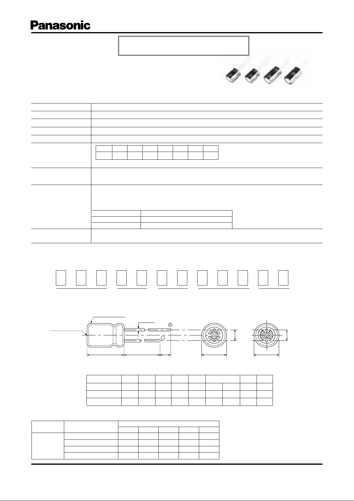
■ Dimensions in mm (not to scale)
Vinyl sleeve
(>6.3mmdia)
Safety vent
L
L<16:L+1.0max
L>20:L+2.0max
Body Dia. φD
Body Length L
Lead Dia. φd
Lead space P
■ Frequency correction factor for ripple current
W.V.
(V.DC)
6.3 to 63
Capacitance
(µF)
6.8 to 330
390 to 1000
1200 to 2200
2700 to 15000
φd±0.05
14 min
4 5 6.3 8 10 12.5 16 18
0.45 0.5 0.5 0.6 0.6 0.6 0.8 0.8 0.8
1.5 2 2.5 3.5 5 5 5 7.5 7.5
60 120 1k
0.55 0.65 0.85 0.90 1.0
0.70 0.75 0.90 0.95 1.0
0.75 0.80 0.90 0.95 1.0
0.80 0.85 0.95 1.00 1.0
Series Code
min
15 to25 30 to 40
Frequency(Hz)
10k
Capacitance code
φ10<
φD+0.5 max
100k
P±0.5
Option
φ8>
P±0.5
φD+0.5 max
Design, Specifications are subject to change without notice. Ask factory for technical specifications before purchase and/or use.
Whenever a doubt about safety arises from this product, please inform us immediately for technical consulation without fail.
– EE26 –
Page 2
Aluminum Electrolytic Capacitor/HFQ
Mar. 2005
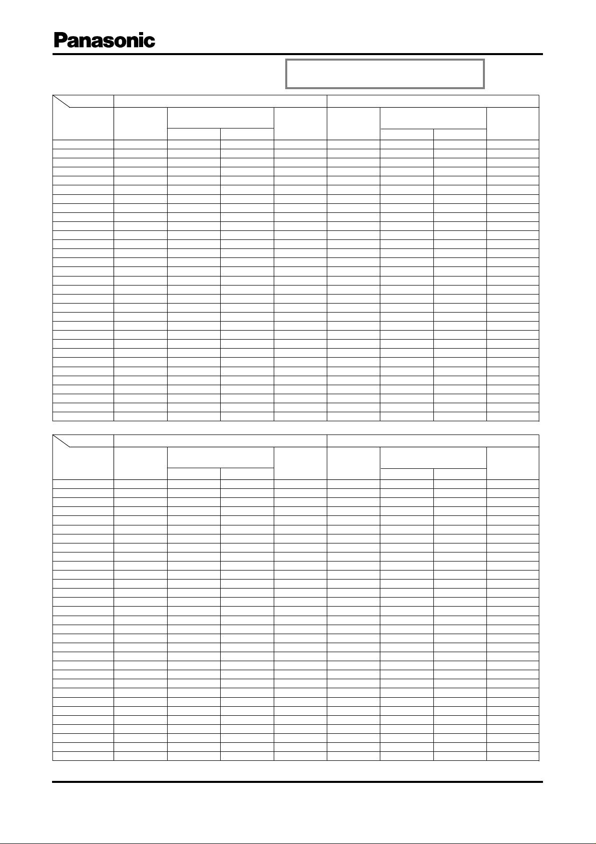
■ Case size / Impedance / Ripple current
W.V.(V.DC)
Case size
(φD×L)
4
×
×
5
×
5
×
6.3
×
6.3
×
8
×
8
×
8
×
10
×
10
×
10
×
10
×
10
×
12.5
×
12.5
×
12.5
×
12.5
×
12.5
×
12.5
×
16
×
16
×
16
×
16
×
16
×
16
×
18
×
18
×
18
×
18
×
18
×
18
11
11
15
11.2
15
11.5
15
20
12.5
16
20
25
30
15
20
25
30
35
40
15
20
25
31.5
35.5
40
15
20
25
31.5
35.5
40
Capacitance
(µF)
68
100
150
220
330
470
680L❉
1000
680
820
1200L❉
1500
2200L❉
1200
2200
2700
3900
4700L❉
5600L❉
2700S❉
4700
5600
6800
8200
12000
3300
5600S❉
6800S❉
10000
12000S❉
15000
6.3 (0J)
Impedance (100kHz)
(W)
-10°C +20°C
2.000
1.300
0.920
0.600
0.400
0.340
0.240
0.180
0.240
0.180
0.130
0.110
0.090
0.130
0.084
0.068
0.060
0.048
0.042
0.092
0.068
0.056
0.050
0.044
0.036
0.076
0.056
0.050
0.046
0.042
0.034
1.000
0.650
0.460
0.300
0.200
0.170
0.120
0.090
0.120
0.090
0.065
0.055
0.045
0.065
0.042
0.034
0.030
0.024
0.021
0.046
0.034
0.028
0.025
0.022
0.018
0.038
0.028
0.025
0.023
0.021
0.017
Discontinued
Ripple current
(100kHz)
(+105°C)
(mA)
120
175
235
290
400
445
575
760
625
795
1015
1190
1440
1010
1400
1690
1950
2220
2390
1360
1730
2070
2350
2550
2900
1620
2000
2200
2800
2900
3000
Capacitance
(µF)
47
82
100
180
220
330
470L❉
680
470
560
1000L❉
1200
1500L❉
1000
1800
2200
2700
3300L❉
3900L❉
1800S❉
3300
3900
5600
6800L❉
8200L❉
2200S❉
3900S❉
5600S❉
6800
8200
10000
Impedance (100kHz)
(Ω)
-10°C +20°C
2.000
1.300
0.920
0.600
0.400
0.340
0.240
0.180
0.240
0.180
0.130
0.110
0.090
0.130
0.084
0.068
0.060
0.048
0.042
0.092
0.068
0.056
0.050
0.044
0.036
0.076
0.056
0.050
0.046
0.042
0.034
10 (1A)
1.000
0.650
0.460
0.300
0.200
0.170
0.120
0.090
0.120
0.090
0.065
0.055
0.045
0.065
0.042
0.034
0.030
0.024
0.021
0.046
0.034
0.028
0.025
0.022
0.018
0.038
0.028
0.025
0.023
0.021
0.017
Ripple current
(100kHz)
(+105°C)
(mA)
120
175
235
290
400
445
575
760
625
795
1015
1190
1440
1010
1400
1690
1950
2220
2390
1360
1730
2070
2350
2550
2900
1620
2000
2200
2800
2900
3000
W.V.(V.DC)
Case size
(φD×L)
4
×
×
5
×
5
×
6.3
×
6.3
×
8
×
8
×
8
×
10
×
10
×
10
×
10
×
10
×
12.5
×
12.5
×
12.5
×
12.5
×
12.5
×
12.5
×
16
×
16
×
16
×
16
×
16
×
16
×
18
×
18
×
18
×
18
×
18
×
18
11
11
15
11.2
15
11.5
15
20
12.5
16
20
25
30
15
20
25
30
35
40
15
20
25
31.5
35.5
40
15
20
25
31.5
35.5
40
Capacitance
(µF)
39
56
82
120
180
270
330L❉
470
330
390
680L❉
820
1200L❉
680
1200
1500
2200L❉
2700L❉
3300L❉
1500S❉
2200
2700
3900
4700L❉
5600
1800
3300S❉
3900S❉
4700
6800
8200
Impedance (100kHz)
(Ω)
16 (1C)
-10°C +20°C
2.000
1.300
0.920
0.600
0.400
0.340
0.240
0.180
0.240
0.180
0.130
0.110
0.090
0.130
0.084
0.068
0.060
0.048
0.042
0.092
0.068
0.056
0.050
0.044
0.036
0.076
0.056
0.050
0.046
0.042
0.034
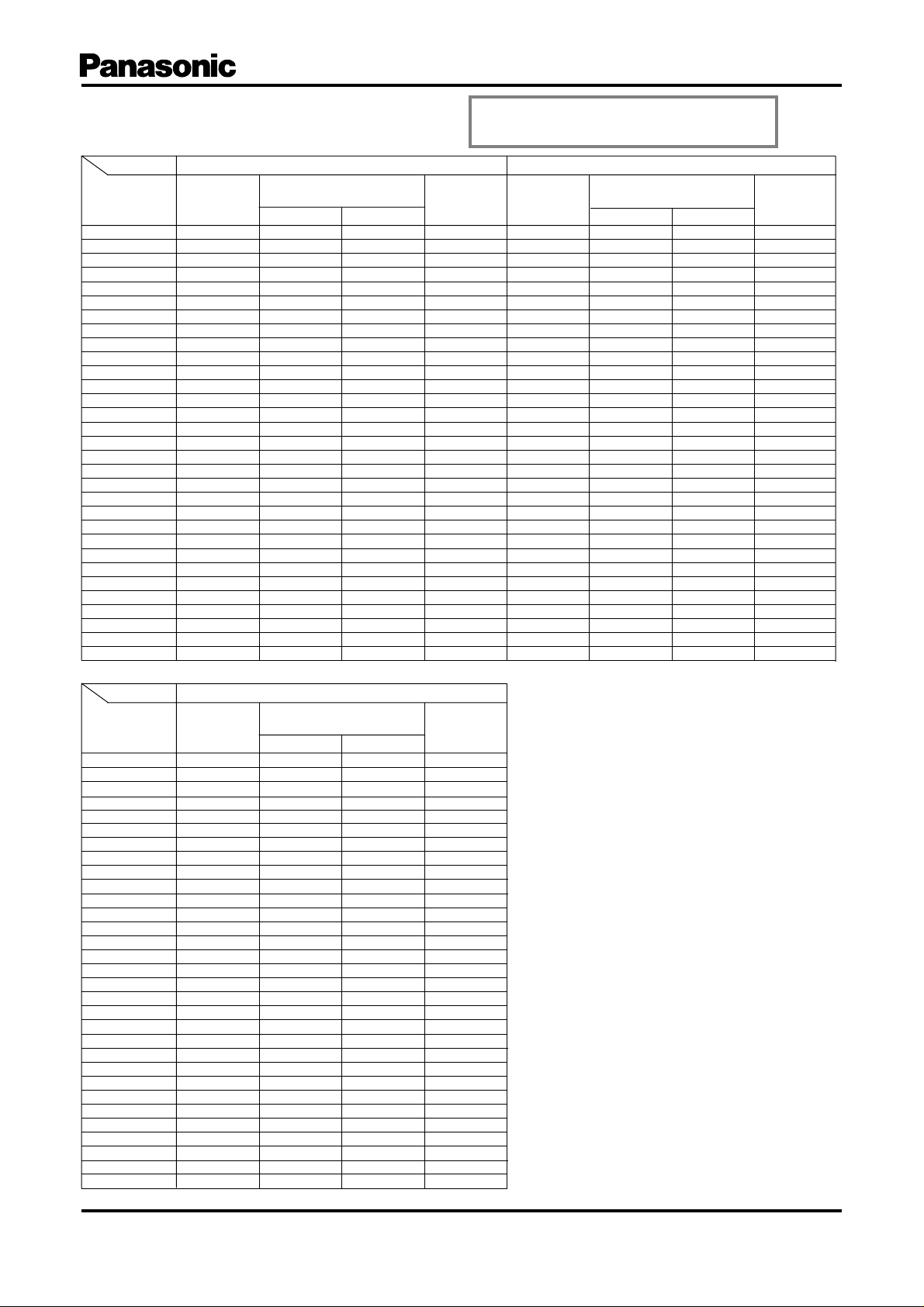
❉ L or S in case size table are optional codes.
1.000
0.650
0.460
0.300
0.200
0.170
0.120
0.090
0.120
0.090
0.065
0.055
0.045
0.065
0.042
0.034
0.030
0.024
0.021
0.046
0.034
0.028
0.025
0.022
0.018
0.038
0.028
0.025
0.023
0.021
0.017
Ripple current
(100kHz)
(+105°C)
(mA)
120
175
235
290
400
445
575
760
625
795
1015
1190
1440
1010
1400
1690
1950
2220
2390
1360
1730
2070
2350
2550
2900
1620
2000
2200
2800
2900
3000
Capacitance
(µF)
27
39
56
82
120
180
220L❉
330
220
270
470L❉
560
820L❉
470
820
1000
1500L❉
1800L❉
2200L❉
820S
1500
1800
2700
3300L❉
3900L❉
1200
2200S❉
2700S❉
3300
3900
4700
25 (1E)
Impedance (100kHz)
(Ω)
-10°C +20°C
2.000
1.300
0.920
0.600
0.400
0.340
0.240
0.180
0.240
0.180
0.130
0.110
0.090
0.130
0.084
0.068
0.060
0.048
0.042
0.092
0.068
0.056
0.050
0.044
0.036
0.076
0.056
0.050
0.046
0.042
0.034
1.000
0.650
0.460
0.300
0.200
0.170
0.120
0.090
0.120
0.090
0.065
0.055
0.045
0.065
0.042
0.034
0.030
0.024
0.021
0.046
0.034
0.028
0.025
0.022
0.018
0.038
0.028
0.025
0.023
0.021
0.017
Ripple current
(100kHz)
(+105°C)
(mA)
120
175
235
290
400
445
575
760
625
795
1015
1190
1440
1010
1400
1690
1950
2220
2390
1360
1730
2070
2350
2550
2900
1620
2000
2200
2800
2900
3000
Design, Specifications are subject to change without notice. Ask factory for technical specifications before purchase and/or use.
Whenever a doubt about safety arises from this product, please inform us immediately for technical consulation without fail.
– EE27 –
Page 3
Aluminum Electrolytic Capacitor/HFQ
Mar. 2005
■ Case size / Impedance / Ripple current
W.V.(V.DC)
Case size
(φD×L)
4
×
×
5
×
5
×
6.3
×
6.3
×
8
×
8
×
8
×
10
×
10
×
10
×
10
×
10
×
12.5
×
12.5
×
12.5
×
12.5
×
12.5
×
12.5
×
16
×
16
×
16
×
16
×
16
×
16
×
18
×
18
×
18
×
18
×
18
×
18
11
11
15
11.2
15
11.5
15
20
12.5
16
20
25
30
15
20
25
30
35
40
15
20
25
31.5
35.5
40
15
20
25
31.5
35.5
40
Capacitance
(µF)•@
18
27
39
56
82
120
150L❉
220
150
180
330L❉
390
560L❉
330
560
680
1000L❉
1200L❉
1500L❉
560S❉
1000
1200
1800
2200L❉
2700L❉
820
1500
1800S❉
2200
2700
3300
35 (1V)
Impedance (100kHz)
(Ω)
-10°C +20°C
2.000
1.300
0.920
0.600
0.400
0.340
0.240
0.180
0.240
0.180
0.130
0.110
0.090
0.130
0.084
0.068
0.060
0.048
0.042
0.092
0.068
0.056
0.050
0.044
0.036
0.076
0.056
0.050
0.046
0.042
0.034
1.000
0.650
0.460
0.300
0.200
0.170
0.120
0.090
0.120
0.090
0.065
0.055
0.045
0.065
0.042
0.034
0.030
0.024
0.021
0.046
0.034
0.028
0.025
0.022
0.018
0.038
0.028
0.025
0.023
0.021
0.017
Discontinued
Ripple current
(100kHz)
(+105°C)
(mA)
120
175
235
290
400
445
575
760
625
795
1015
1190
1440
1010
1400
1690
1950
2220
2390
1360
1730
2070
2350
2550
2900
1620
2000
2200
2800
2900
3000
Capacitance
(µF)
10
18
27
33
56
68
100
150
82
120
220L❉
270
390L❉
220
330
470
560
680L❉
820L❉
390
680
820
1000
1200L❉
1500L❉
470S❉
680S❉
1000S❉
1200
1500
1800
50 (1H)
Impedance (100kHz)
(Ω)
-10°C +20°C
5.000
2.600
1.800
1.200
0.800
0.600
0.460
0.320
0.460
0.320
0.220
0.180
0.150
0.260
0.160
0.140
0.120
0.100
0.086
0.168
0.106
0.088
0.066
0.056
0.052
0.140
0.100
0.082
0.062
0.054
0.050
2.500
1.300
0.900
0.600
0.400
0.300
0.230
0.160
0.230
0.160
0.110
0.090
0.075
0.130
0.080
0.070
0.060
0.050
0.043
0.084
0.053
0.044
0.033
0.028
0.026
0.070
0.050
0.041
0.031
0.027
0.025
Ripple current
(100kHz)
(+105°C)
(mA)
90
155
215
260
360
410
500
670
510
640
890
1040
1300
920
1200
1440
1680
1850
2010
1270
1470
1810
2120
2260
2410
1470
1810
2000
2220
2460
2560
W.V.(V.DC)
Case size
(φD×L)
×
4
×
5
×
5
×
6.3
×
6.3
×
8
×
8
×
8
×
10
×
10
×
10
×
10
×
10
×
12.5
×
12.5
×
12.5
×
12.5
×
12.5
×
12.5
×
16
×
16
×
16
×
16
×
16
×
16
×
18
×
18
×
18
×
18
×
18
×
18
11
11
15
11.2
15
11.5
15
20
12.5
16
20
25
30
15
20
25
30
35
40
15
20
25
31.5
35.5
40
15
20
25
31.5
35.5
40
Capacitance
(µF)
6.8
12
18
22
39
56
82
100L❉
68
100
150L❉
180
270L❉
150
220
330
390
470L❉
560L❉
270
470
560
680
820
1000L❉
330S❉
560S❉
680S❉
1000
1200
1500
63 (1J)
Impedance (100kHz)
(Ω)
-10°C +20°C
7.000
4.000
2.600
2.000
1.400
0.760
0.600
0.380
0.600
0.380
0.280
0.240
0.190
0.320
0.190
0.180
0.160
0.130
0.120
0.200
0.140
0.120
0.100
0.084
0.068
0.170
0.130
0.114
0.096
0.082
0.066
3.500
2.000
1.300
1.000
0.700
0.380
0.300
0.190
0.300
0.190
0.140
0.120
0.095
0.160
0.095
0.090
0.080
0.065
0.060
0.100
0.070
0.060
0.050
0.042
0.034
0.085
0.065
0.057
0.048
0.041
0.033
Ripple current
(100kHz)
(+105°C)
(mA)
80
145
200
240
330
370
450
600
470
580
820
950
1110
890
1140
1420
1620
1780
1950
1220
1450
1750
2050
2220
2370
1410
1750
1940
2110
2300
2510
Design, Specifications are subject to change without notice. Ask factory for technical specifications before purchase and/or use.
Whenever a doubt about safety arises from this product, please inform us immediately for technical consulation without fail.
– EE28 –
Page 4

Aluminum Electrolytic Capacitor
Mar. 2005
Application Guidelines
1. Circuit Design
Ensure that operational and mounting conditions
follw the specified conditions detailed in the catalog
and specification sheets.
1.1 Operating Temperature and Frequency
Electrolytic capacitor electrical parameters are
normally specified at 20°C temperature and 120Hz
frequency. These pa rameter s vary with changes in
temperature and frequency. Circuit designers
should take these changes into consideration.
(1) Effects of operating temperature on electrical
parameters
a)At higher temperatures, leakage current and
capacitance increase while equivalent series
resistance(ESR) decreases.
b)At lower temperatures, leakage current and
capacitance decrease while equivalent series
resistance(ESR) increases.
(2) Effects of frequency on electrical parameters
a)At higher frequencies, capacitance and
impedance decrease while tan δ increases.
b)At lower frequencies, ripple current generated
heat will rise due to an increase in equivalent
series resistance (ESR).
1.2 Operating Temperature and Life Expectancy
(1) Expected life is affected by operating temperature.
Generally, each 10°C reduction in temperature
will double the expected life. Use capacitors at
the lowest possible temperature below the
maximum guaranteed temperature.
(2) If operating conditions exceed the maximum
guaranteed limit, rapid eIectrical parameter
deterioration will occur, and irreversible damage
will result.
Check for maximum capacitor operating tempera tures including ambient temperature, internal
capacitor temperature rise caused by ripple current,
and the effects of radiated heat from power
transistors, IC?s or resistors.
Avoid placing components which could conduct
heat to the capacitor from the back side of the circuit
board.
(3)The formula for calculating expected Iife at lower
operating temperatures is as fllows;
T1-T2
L
2 = L1 x 2 where,
1: Guaranteed life (h) at temperature, T1° C
L
L
2: Expected life (h) at temperature,T2°C
T
1: Maximum operating temperature (°C)
T
2: Actual operating temperature, ambient
temperature + temperature rise due to
ripple currentheating(°C)
A quick eference capacitor guide for estimating
exected life is included for your reference.
10
■ Expected Life Estimate Quick Reference Guide
1. 85°C2000h
2.105°C1000h
3.105°C2000h
4.105°C5000h
24h
operation
8h/d
Capacitor Ambient Temperature
(h)
Years
Years
120
110
100
3
2
90
1
80
70
60
50
40
2000 5000 10,000 20,000 50,000 100,000 200,000
4
1 2 3 4 5 7 20
3
6 10 15 20 30
■ Failure rate curve
Initial failure period
Random failure period
Life Time
Failure rate
Time
Wear failure period
Design, Specifications are subject to change without notice. Ask factory for technical specifications before purchase and/or use.
Whenever a doubt about safety arises from this product, please inform us immediately for technical consulation without fail.
– EE16 –
Page 5

Aluminum Electrolytic Capacitor
Mar. 2005
■ Typical failure modes and their factors
Faliure mode Faliure mechanism (internal phenomenon) Production factor Application factor
Overvoltage applied
Vent operates
Capacitance
reduction
tan d increase
Leakage current
increase
Short circuit
•
•
•
Increase in
internal pressure
Reduced anode foil
capacitance
Reduced cathode
foil capacitance
Deterioration of
oxide film
•
Electrolyte evaporation
Insulation breakdown of film
or electrolytic paper
•
Increase in internal temperature
•
•
•
•
••
•
Defect of oxide film
•
•
•
•
Metal particles
in capacitor
•
Burr(s) on foil leads
Insufficient
electrolyte
•
Excessive ripple current
Reverse voltage applied
•
Severe charging-discharging
•
AC voltage applied
•
Used for a high temperature
Used for a long period of time
Stress applied to leads
Leads improperly
connected
•
Open
Design, Specifications are subject to change without notice. Ask factory for technical specifications before purchase and/or use.
Whenever a doubt about safety arises from this product, please inform us immediately for technical consulation without fail.
••
Corrosion Infiltration of Cl
Mechanical stressLeads improperly connected
Use of Halogenated solvent
•
Use of adhesive
Use of coating material
– EE17 –
Page 6

Aluminum Electrolytic Capacitor
Mar. 2005
1.3 Common Application Conditions to Avoid
The following misapplication load conditions will
cause rapid deterioration to capacitor electrical
parameters. ln addition, rapid heating and gas
generation within the capacitor can occur causing
the pressure relief vent to operate and resuItant
leakage of electrolyte. Under extreme conditions,
explosion and fire could result. Leakinq electrolyte
is combustible and electrically conductive.
(1) Reverse Voltaqe
DC capacitors have polarity. Verify correct polar ity
before insertion. For circuits with chan ging or
uncertain polarity,use DC bipolar capacitors. DC
bipolar capacitors are not suitable for use in AC
circuits.
(2) Charqe/Discharqe Applications
Standard capacitors are not suitable for use in
repeating charge/discharge applications. For
charqe/discharqe applications consult us and advise
actual conditions.
(3) Overvoltage
Do not appIy voltaqes exceeding the maximum
specified rated voltages. Voltage up to the surge
voltage rating are acceptable for short periods of
time. Ensure that the sum of the DC voltage and
the superimposed AC ripple voltage does not
exceed the rated voltage.
(4) Ripple Current
Do not apply ripple currents exceeding the maximum
specified value. For high ripple current applications,
use a capacitor designed for high rippIe currents
or contact us with your requirements.
Ensure that allowable ripple currents superimposed
on low DC bias voltages do not cause reverse voltage
conditions.
1.4 Using Two or More Capacitors in Series
or Parallel
(1) Capacitors Connected in Parallel
The circuit resistance can closely approximate the
series resistance of the capacitor causing an
imbalance of ripple current loads w ithin the
capacitors. Careful design of wiring methods can
minimize the possibility of excessive ripple currents
applied to a capacitor.
(2) Capacitors Connected in Series
Nor mal DC leakage current differences among
capacitors can cause voltage imbalances. The use
of voltage divider shunt resistors with consideration
to leakage currents, can prevent capacitor voltage
imbaIances.
1.5 Capacitor Mounting Considerations
(1) DoubIe - Sided Circuit Boards
Avoid wiring Pattern runs which pass between
the mounted capacitor and the circuit board. When
dipping into a solder bath, excess solder may collect
under the capacitor by capillar y action and
shortcircuit the anode and cathode ter minals.
(2) Circuit Board Hole Positioning
The vinyl sleeve of the capacitor can be damaged
if solder passes through a lead hole for
subsequently processed parts. Special care when
locating hole positions in pr oximity to capacitors is
recommended.
(3) Circuit Board Hole Spacing
The circuit board holes spacing should match the
capacitor lead wire spacing within the specified
tolerances. Incorrect spacing can cause excessive
lead wire stress du ring the insertion process. This
may resuIt in p remature capacitor failure due to
short or open circuit, increased leakage current,
or electrolyte leakage.
(4)Land/Pad Pattern
The circuit board land/pad pattern size for chip
capacitors is specified in the following table.
[Table of Board Land Size vs. Capacitor Size]
c
b a b
Size
A(φ3)
B(φ4)
C(φ5)
D(φ6.3)
E(φ8 x 6.2L)
F(φ8 x 10.2L)
G(φ10 x 10.2L)
Among others, when the size a is wide , back fillet can
not be made, decreasing fitting strength.
❉ Decide considering mounting condition, solderability
and fitting strength, etc. based on the design
standards of your company.
Board land part
a
0.6
1.0
1.5
1.8
2.2
3.1
4.6
b
2.2
2.5.
2.8
3.2
4.0
4.0
4.1
(mm)
c
1.5
1.6
1.6
1.6
1.6
2.0
2.0
Design, Specifications are subject to change without notice. Ask factory for technical specifications before purchase and/or use.
Whenever a doubt about safety arises from this product, please inform us immediately for technical consulation without fail.
– EE18 –
Page 7

Aluminum Electrolytic Capacitor
Mar. 2005
(5)Clearance for Case Mounted Pressure
Relief Vents
Capacitors with case mounted pressure relief vents
require sufficient clearance to allow for proper vent
operation. The minimum c learances are dependent
on capacitor diameters as follows.
f6.3 to f16 mm : 2 mm minimum,
f18 to f35 mm : 3 mm minimum.
f40 mm or greater: 5 mm minimum
(6)Clearance for Seal Mounted Pressure
Relief Vents
A hole in the circuit board directly under the seal
vent location is required to allow proper release
of pressure.
(7)Wiring Near the Pressure Relief Vent
Avoid locating high voltage or high current wiring
or circuit board paths above the pressure relief
vent. Flammable, high temperature gas exceeding
100°C may be rel eased which could dissolve the
wire insulation and ignite.
(8)Circuit Board Patterns Under the Capacitor
Avoid circuit board runs under the capacitor as
electrolyte leakage could cause an electrical short.
(9)Screw Terminal Capacitor Mounting
● Do not orient the capacitor with the screw terminal
side of the capacitor facing downwards.
● Tighten the terminal and mounting bracket screws
within the torque range specified in the
specification.
1.6Electrical Isolation of the Capacitor
Completely isolate the capacitor as follows.
● Between the cathode and the case (except for
axially leaded B types) and between the anode
terminal and other circuit paths.
● Between the extra mounting terminals (on T types)
and the anode terminal, cathode terminal, and
other circuit paths.
1.7Capacitor Sleeve
The vinyl sleeve or laminate coating is intended for
mar king and identification purposes and is not meant
to electrically insulate the capacitor.
The sleeving may split or crack if immersed into
solvents such as toluene or xylene, and then exposed
to high temperatures.
2. Capacitor Handling Techniques
2.1Considerations Before Using
(1) Capacitors have a finite life. Do not reuse or
recycle capacitors from used equipment.
(2) Transient recovery voltage may be generated in
the capacitor due to dielectric absorption. If
required, this voltage can be discharged with a
resistor with a value of about 1 kΩ.
(3) Capacitors stored for long periods of time may
exhibit an increase in leakage current. This can
be corrected by gradually applying rated voltage
in series with a resistor of approximately 1 kΩ.
(4) If capacitors are dropped, they can be damaged
mechanically or electrically. Avoid using dropped
capacitors.
(5) Dented or crushed capacitors should not be
used. The seal integrity can be compromised
and loss of electrolyte/shortened life can result.
2.2Capacitor Insertion
(1) Verify the correct capacitance and rated voltage
of the capacitor.
(2) Verify the correct polarity of the capacitor before
inserting.
(3)
Verify the correct hole spacing before insertion
(land pattern size on chip type) to avoid stress
on the terminals.
(4) Ensure that the auto insertion equipment lead
clinching operation does not stress the capacitor
leads where they enter the seal of the capacitor.
For chip type capacitors, excessive mounting
pressure can cause high leakage current, short
circuit, or disconnection.
2.3Manual Soldering
(1) Observe temperature and time soldering
specifications or do not exceed temperatures of
350°C for 3 seconds or less.
(2) If lead wires must be formed to meet terminal
board hole spacing, avoid stress on the leadwire
where it enters the capacitor seal.
(3) If a soldered capacitor must be removed and
reinserted, avoid excessive stress to the capacitor
leads.
(4) Aviod touching the tip of the soldering iron to the
capacitor, to prevent melting of the vinyl sleeve.
Always consider safety when designing equipment
and circuits. Plan for worst case failure modes such
as short circuits and open circuits which could occur
during use.
(1)Provide protection circuits and protection devices
to allow safe failure modes.
(2)Design redundant or secondary circuits where
possible to assure continued operation in case of
main circuit failure.
Design, Specifications are subject to change without notice. Ask factory for technical specifications before purchase and/or use.
Whenever a doubt about safety arises from this product, please inform us immediately for technical consulation without fail.
– EE19 –
Page 8

Aluminum Electrolytic Capacitor
Mar. 2005
2.4 Flow Soldering
(1) Don not immerse the capacitor body into the
solder bath as excessive internal pressure could
result.
(2) Observe proper soldering conditions (temperature,
time, etc.). Do not exceed the specified limits.
(3) Do not allow other parts or components to touch
the capacitor during soldering.
2.5 Reflow Soldering for Chip Capacitors
(1) For reflow, use a thermal conduction system such
as infrared radiation (IR) or hot blast. Vapor heat
transfer systems (VPS) are not recommended.
(2) Observe proper soldering conditions (temperature,
time, etc.). Do not exceed the specified limits.
(3) Reflow should be performed one time. Consult us
for additional reflow restrictions.
250
200
160°C
150
100
50
Parts upper part temperature (°C)
Chip capacitor reflow guaranteed condition
240
230
120(s)
Time
5(s)
Peak
temperature
Time in
200°C or more
2.6 Other Soldering Considerations
Rapid temperature rises during the preheat
operation and resin bonding operation can cause
cracking of the capacitor vinyl sleeve. For heat
curing, do not exceed 150°C for a maximum time of
2 minutes.
2.7 Capacitor Handling after Soldering
(1) Avoid movement of the capacitor after soldering
to prevent excessive stress on the leadwires
where they enter the seal.
(2) Do not use the capacitor as a handle when
moving the circuit board assembly.
(3) Avoid striking the capacitor after assembly to
prevent failure due to excessive shock.
2.8 Circuit Board Cleaning
(1) Circuit boards can be immersed or ultrasonically
cleaned using suitable cleaning solvents for up
to 5 minutes and up to 60°C maximum
temperatures. The boards should be thoroughly
rinsed and dried.
Recommended cleaning solvents include
Pine Alpha ST-100S, Sunelec B-12, DK Beclear
CW-5790, Aqua Cleaner 210SEP, Cold Cleaner
P3-375, Telpen Cleaner EC-7R, Clean-thru 750H,
Clean-thru 750L, Clean thru 710M, Techno
Cleaner 219, Techno Care FRW-17, Techno
Care FRW-1, Techno Care FRV-1, IPA (isopropyl
alcohol)
220
210
Peak temper ature (°C)
0 10 20 30 40 50 60
240
230
220
210
Peak temperature (°C)
0 10 20 30 40 50 60
240
Time in 200°C or more (s)
(φ3 to 6.3φ)
Time in 200°C or more (s)
(φ8 to φ10)
EB Series
230
220
210
Peak temper ature (°C)
✽ The use of ozone depleting cleaning agents are
not recommended in the interest of protecting
the environment.
(2) Avoid using the following solvent groups unless
specifically allowed for in the specification;
● Halogenated cleaning solvents: except for solvent
resi stant capacitor types, halogenated solvents
can permeate the seal and cause internal
capacitor corrosion and failure. For solvent
resistant capacitors, carefully follow the
temperature and time requirements of the
specificaion. 1-1-1 trichloroe thane should never
be used on any aluminium electrolytic capacitor.
● Alkali solvents: could attack and dissolve the
aluminum case.
● Petroleum based solvents: deterioration of the
rubber seal could result.
● Xylene: deterioration of the rubber seal could
result.
● Acetone: removal of the ink markings on the
vinyl sleeve could result.
0 10 20 30 40 50 60
Time in 200°C or more (s)
(φ10 to φ18)
✽ Temperature measuring method: Measure
temperature in assuming quantitative production, by
sticking the thermo-couple to the capacitor upper
part with epoxy adhesives.
Design, Specifications are subject to change without notice. Ask factory for technical specifications before purchase and/or use.
Whenever a doubt about safety arises from this product, please inform us immediately for technical consulation without fail.
– EE20 –
Page 9

Aluminum Electrolytic Capacitor
Mar. 2005
(3) A thorough drying after cleaning is required to
remove residual cleaning solvents which may be
trapped between the capacitor and the circuit
board. Avoid drying temperatures which exceed
the maximum rated temperature of the capacitor.
(4) Monitor the contamination levels of the cleaning
solvents during use by electrical conductivity, pH,
specific gravity, or water content. Chlorine levels
can rise with contamination and adversely affect
the performance of the capacitor.
✽ Please consult us for additonal information about
acceptable cleaning solvents or cleaning methods.
Type
Surface mount type
Lead type
Snap-in type
Series
V(Except EB
Series)
Bi-polar SU
M
KA
Bi-polar KA
FB
FC
GA
NHG
EB
TA
TS UP
TS HA
Cleaning permitted
L
L
L(~ 100V)
L
L
L
L
L
L(~ 100V)
L(~ 100V)
L
L(~ 100V)
L(~ 100V)
2.9Mounting Adhesives and Coating Agents
When using mounting adhesives or coating agents to
control humidity, avoid using materials containing
halogenated solvents. Also, avoid the use of
chloroprene based polymers.
✽ After applying adhesives or coatings, dry thoroughly
to prevent residual solvents from being trapped
between the capacitor and the circuit board.
3. Precautions for using capacitors
3.1Environmental Conditions
Capacitors should not be used in the following
environments.
(1) Temperature exposure above the maximum rated
or below the minimum rated temperature of the
capacitor.
(2) Direct contact with water, salt water, or oil.
(3) High humidity conditions where water could
condense on the capacitor.
(4) Exposure to toxic gases such as hydrogen sulfide,
sulfuric acid, nitric acid, chlorine, or ammonia.
(5) Exposure to ozone, radiation, or ultraviolet rays.
(6) Vibration and shock conditions exceeding
specified requirements.
3.2Electrical Precautions
(1) Avoid touching the terminals of the capacitor as
possible electric shock could result. The exposed
aluminium case is not insulated and could also
cause electric shock if touched.
(2)Avoid short circuiting the area between the
capacitor terminals with conductive materials
including liquids such as acids or alkaline solutions.
4. Emergency Procedures
(1) If the pressure relief vent of the capacitor
operates, immediately turn off the equipment and
disconnect from the power source. This will
minimize additional damage caused by the
vaporizing electrolyte.
(2) Avoid contact with the escaping electrolyte gas
which can exceed 100°C temperatures.
If electrolyte or gas enters the eye, immediately
flush the eye with large amounts of water.
If electrolyte or gas is ingested by mouth, gargle
with water. If electrolyte contacts the skin, wash
with soap and water.
5. Long Term Storage
Leakage current of a capacitor increases with long
storage times. The aluminium oxide film deteriorates
as a function of temperature and time. If used
without reconditioning, an abnormally high current
will be required to restore the oxide film. This current
surge could cause the circuit or the capacitor to fail.
Capacitor should be reconditioned by applying rated
voltage in series with a 1000 Ω, current limiting
resistor for a time period of 30 minutes.
5.1Environmental Conditions (Storage)
Capacitors should not be stored in the following
environments.
(1) Temperature exposure above 35°C or below 15 °C.
(2) Direct contact with water, salt water, or oil.
(3) High humidity conditions where water could
condense on the capacitor.
(4) Exposure to toxic gases such as hydrogen
sulfide,sulfuric acid, nitric acid, chlorine, or
ammonia.
(5) Exposure to ozone, radiation, or ultraviolet rays.
(6) Vibration and shock conditions exceeding
specified requirements.
Design, Specifications are subject to change without notice. Ask factory for technical specifications before purchase and/or use.
Whenever a doubt about safety arises from this product, please inform us immediately for technical consulation without fail.
– EE21 –
Page 10

6. Capacitor Disposal
Mar. 2005
When disposing of capacitors, use one of the
following methods.
● Incinerate after crushing the capacitor or
puncturing the can wall (to prevent explosion due
to internal pressure rise). Capacitors should be
incinerated at high temperatures to prevent the
release of toxic gases such as chlorine from the
polyvinyl chloride sleeve, etc.
● Dispose of as solid waste.
● Local laws may have specific disposal
requirements which must be followed.
The application guidelines above are taken from:
Technical Report EIAJ RCR-2367 issued by the Japan
Electronic Industry Association, Inc. Guideline of notabilia for aluminium electrolytic
capacitors with non-solid electrolytic for use in
electronic equipment.
Refer to this Technical Report for additional details.
Aluminum Electrolytic Capacitor
Design, Specifications are subject to change without notice. Ask factory for technical specifications before purchase and/or use.
Whenever a doubt about safety arises from this product, please inform us immediately for technical consulation without fail.
– EE22 –
 Loading...